

Page 1
DLP® Projector
User manual
Page 2

TABLE OF CONTENTS
SAFETY ............................................................................................... 4
Important Safety Instruction....................................................................................................... 4
Laser Radiation Safety Information ........................................................................................... 5
Copyright ................................................................................................................................... 6
Disclaimer .................................................................................................................................. 6
Trademark Recognition ............................................................................................................. 6
FCC ........................................................................................................................................... 6
Declaration of Conformity for EU countries ............................................................................... 7
WEEE ........................................................................................................................................ 7
INTRODUCTION .................................................................................. 8
Package Overview..................................................................................................................... 8
Standard accessories ................................................................................................................ 8
Optional accessories ................................................................................................................. 8
Product Overview ...................................................................................................................... 9
Connections.............................................................................................................................. 10
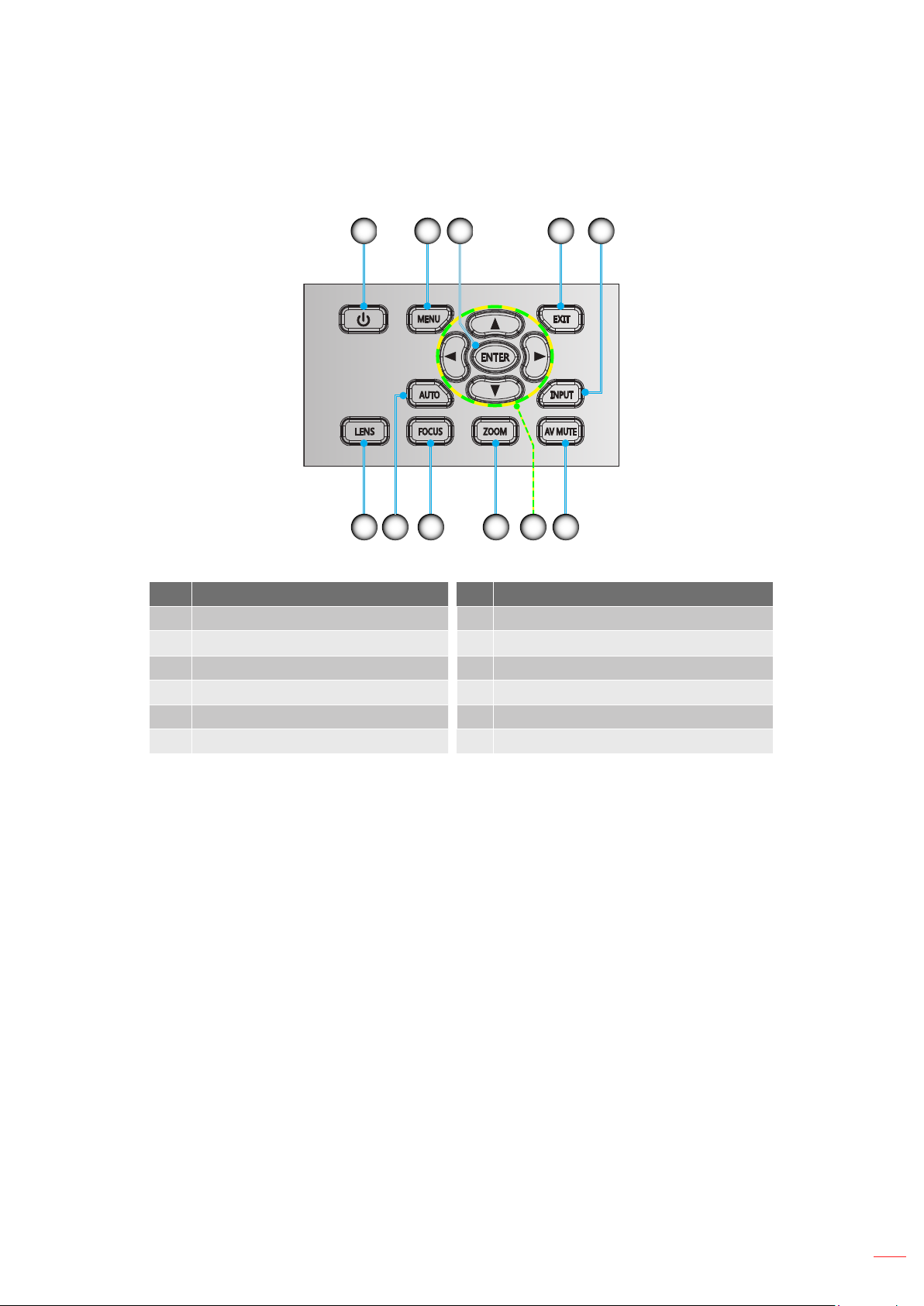
Keypad ..................................................................................................................................... 11
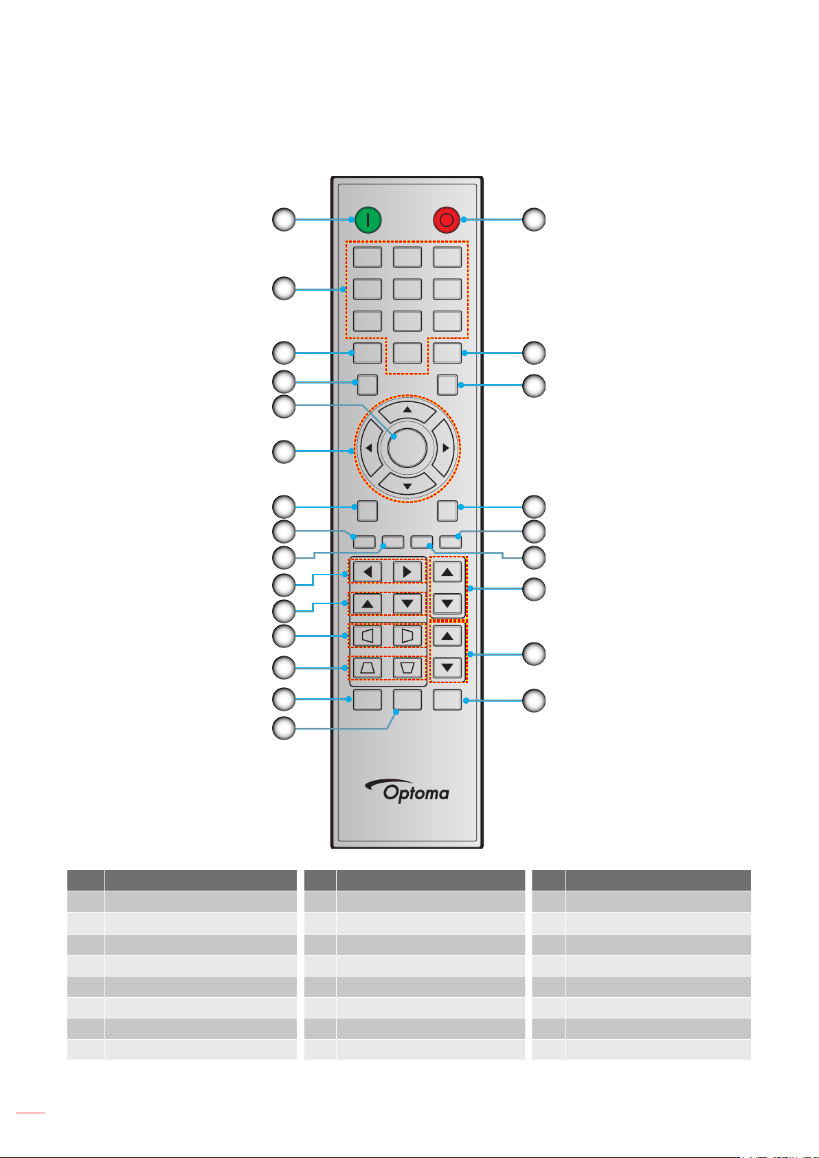
Remote control ......................................................................................................................... 12
SETUP AND INSTALLATION ............................................................. 13
Installing the projection lens ..................................................................................................... 13
Adjusting the projector position ................................................................................................ 15
Connecting sources to the projector ......................................................................................... 16
Adjusting the projector image ................................................................................................... 17
Remote setup ........................................................................................................................... 18
USING THE PROJECTOR .................................................................. 20
Powering on / off the projector.................................................................................................. 20
Selecting an input source ......................................................................................................... 21
Menu navigation and features .................................................................................................. 22
OSD Menu tree......................................................................................................................... 23
PICTURE menu ........................................................................................................................ 29
OUTPUT menu ......................................................................................................................... 34
SETUP menu ............................................................................................................................ 38
Setup network control settings menu ....................................................................................... 43
OPTION menu .......................................................................................................................... 48
2
English
Page 3

ADDITIONAL INFORMATION ............................................................ 52
Compatible resolutions ............................................................................................................. 52
Image size and projection distance .......................................................................................... 54
Projector dimensions and ceiling mount installation ................................................................. 55
IR remote codes ....................................................................................................................... 56
Troubleshooting ........................................................................................................................ 59
Warning indicators .................................................................................................................... 61
Specications ........................................................................................................................... 63
Optoma global ofces ............................................................................................................... 64
English
3
Page 4

SAFETY
The lightning ash with arrow head within an equilateral triangle is
intended to alert the user to the presence of uninsulated "dangerous
voltage" within the product's enclosure that may be of sufcient
magnitude to constitute a risk of electric shock to persons.
The exclamation point within an equilateral triangle is intended to alert
the user to the presence of important operating and maintenance
(servicing) instructions in the literature accompanying the appliance.
Please follow all warnings, precautions and maintenance as recommended in this user's guide.
Important Safety Instruction
Do not block any ventilation openings. To ensure reliable operation of the projector and to protect from
over heating, it is recommended to install the projector in a location that does not block ventilation.
As an example, do not place the projector on a crowded coffee table, sofa, bed, etc. Do not put the
projector in an enclosure such as a book case or a cabinet that restricts air ow.
To reduce the risk of re and/or electric shock, do not expose the projector to rain or moisture. Do not
install near heat sources such as radiators, heaters, stoves or any other apparatus such as ampliers
that emits heat.
Do not let objects or liquids enter the projector. They may touch dangerous voltage points and short
out parts that could result in re or electric shock.
Do not use under the following conditions:
± In extremely hot, cold or humid environments.
(i) Ensure that the ambient room temperature is within 5°C ~ 40°C
(ii) Relative humidity is 10% ~ 85%
± In areas susceptible to excessive dust and dirt.
± Near any appliance generating a strong magnetic eld.
± In direct sunlight.
Do not use the projector in places where ammable gases or explosives gases may be present in the
atmosphere. The lamp inside the projector becomes very hot during operation and the gases may
ignite and result in a re.
Do not use the unit if it has been physically damaged or abused. Physical damage/abuse would be
(but not limited to):
± Unit has been dropped.
± Power supply cord or plug has been damaged.
± Liquid has been spilled on to the projector.
± Projector has been exposed to rain or moisture.
4
± Something has fallen in the projector or something is loose inside.
Do not place the projector on an unstable surface. The projector may fall over resulting in injury or the
projector may become damaged.
Do not block the light coming out of the projector lens when in operation. The light will heat the object
and my melt, cause burns or start a re.
Please do not open or disassemble the projector as this may cause electric shock.
Do not attempt to service the unit yourself. Opening or removing covers may expose you to dangerous
voltages or other hazards. Please call Optoma before you send the unit for repair.
See projector enclosure for safety related markings.
The unit should only be repaired by authorized service personnel.
English
Page 5

Only use attachments/accessories specied by the manufacturer.
Do not look into straight into the projector lens during operation. The bright light may harm your eyes.
This projector will detect the life of the lamp itself.
When switching the projector off, please ensure the cooling cycle has been completed before
disconnecting power. Allow 90 seconds for the projector to cool down.
Turn off and unplug the power plug from the AC outlet before cleaning the product.
Use a soft dry cloth with mild detergent to clean the display housing. Do not use abrasive cleaners,
waxes or solvents to clean the unit.
Disconnect the power plug from AC outlet if the product is not being used for a long period of time.
Do not setup the projector in places where it might be subjected to vibration or shock.
Do not touch the lens with bare hands.
Remove battery/batteries from remote control before storage. If the battery/batteries are left in the
remote for long periods, they may leak.
Do not use or store the projector in places where smoke from oil or cigarettes may be present, as it
can adversely affect the quality of the projector performance.
Please follow the correct projector orientation installation as non standard installation may affect the
projector performance.
Use a power strip and or surge protector. As power outages and brown-outs can KILL devices.
Laser Radiation Safety Information
This product is classied as Class 3R of IEC60825-1 : 2007 and also complies with 21 CFR 1040.10
and 1040.11 except for deviations pursuant to Laser Notice No. 50, dated June 24, 2007.
IEC 60825-1:2014: CLASS 1 LASER PRODUCT - RISK GROUP 2
Explanatory label is shown all information of laser power.
CLASS 3R LASER PRODUCT-AVOID DIRECT EYE EXPOSURE.
Laser aperture is from projection lens, DO NOT LOOK INTO THE LENS.
LASER APERTURE
DO NOT LOOK INTO THE LENS
This projector has built-in Class 4 laser module. Disassembly or modication is very dangerous and
should never be attempted.
Any operation or adjustment not specically instructed by the user manual creates the risk of
hazardous laser radiation exposure.
Do not open or disassemble the projector as this may cause damage by the exposure of laser
radiation.
Do not stare into beam when the projector is on. The bright light may result in permanent eye damage.
When turning on the projector, make sure no one within projection range is looking at the lens.
Without following the control, adjustment or operation procedure may cause damage by the exposure
of laser radiation.
English
5
Page 6

Adequate instructions for assembly, operation, and maintenance, including clear warnings concerning
precautions to avoid possible exposure to laser and collateral radiation in excess of the accessible
emission limits in Class 3R.
Copyright
This publication, including all photographs, illustrations and software, is protected under international copyright
laws, with all rights reserved. Neither this manual, nor any of the material contained herein, may be reproduced
without written consent of the author.
© Copyright 2015
Disclaimer
The information in this document is subject to change without notice. The manufacturer makes no representations
or warranties with respect to the contents hereof and specically disclaims any implied warranties of
merchantability or tness for any particular purpose. The manufacturer reserves the right to revise this publication
and to make changes from time to time in the content hereof without obligation of the manufacturer to notify any
person of such revision or changes.
Trademark Recognition
Kensington is a U.S. registered trademark of ACCO Brand Corporation with issued registrations and pending
applications in other countries throughout the world.
HDMI, the HDMI Logo, and High-Denition Multimedia Interface are trademarks or registered trademarks of HDMI
Licensing LLC in the United States and other countries.
, DLP Link and the DLP logo are registered trademarks of Texas Instruments and BrilliantColorTM is a
DLP
trademark of Texas Instruments.
All other product names used in this manual are the properties of their respective owners and are
Acknowledged.
FCC
This device has been tested and found to comply with the limits for a Class A digital device pursuant to Part 15
of the FCC rules. These limits are designed to provide reasonable protection against harmful interference in a
residential installation. This device generates, uses and can radiate radio frequency energy and, if not installed and
used in accordance with the instructions, may cause harmful interference to radio communications.
However, there is no guarantee that interference will not occur in a particular installation. If this device does cause
harmful interference to radio or television reception, which can be determined by turning the device off and on is
encouraged to try to correct the interference by one or more of the following measures:
Reorient or relocate the receiving antenna.
Increase the separation between the device and receiver.
Connect the device into an outlet on a circuit different from that to which the receiver is connected.
Consult the dealer or an experienced radio/television technician for help.
Notice: Shielded cables
All connections to other computing devices must be made using shielded cables to maintain compliance with FCC
regulations.
Caution
Changes or modications not expressly approved by the manufacturer could void the user's authority, which is
granted by the Federal Communications Commission, to operate this projector.
English
6
Page 7

Operation Conditions
This device complies with Part 15 of the FCC Rules. Operation is subject to the following two conditions:
1. This device may not cause harmful interference and
2. This device must accept any interference received, including interference that may cause undesired operation.
Notice: Canadian users
This Class A digital apparatus complies with Canadian ICES-003.
Remarque à l’intention des utilisateurs canadiens
Cet appareil numerique de la classe A est conforme a la norme NMB-003 du Canada.
Declaration of Conformity for EU countries
EMC Directive 2004/108/EC (including amendments)
Low Voltage Directive 2006/95/EC
R & TTE Directive 1999/5/EC (if product has RF function)
WEEE
Disposal instructions
Do not throw this electronic device into the trash when discarding. To minimize pollution and ensure
utmost protection of the global environment, please recycle it.
English
7
Page 8
INTRODUCTION
Package Overview
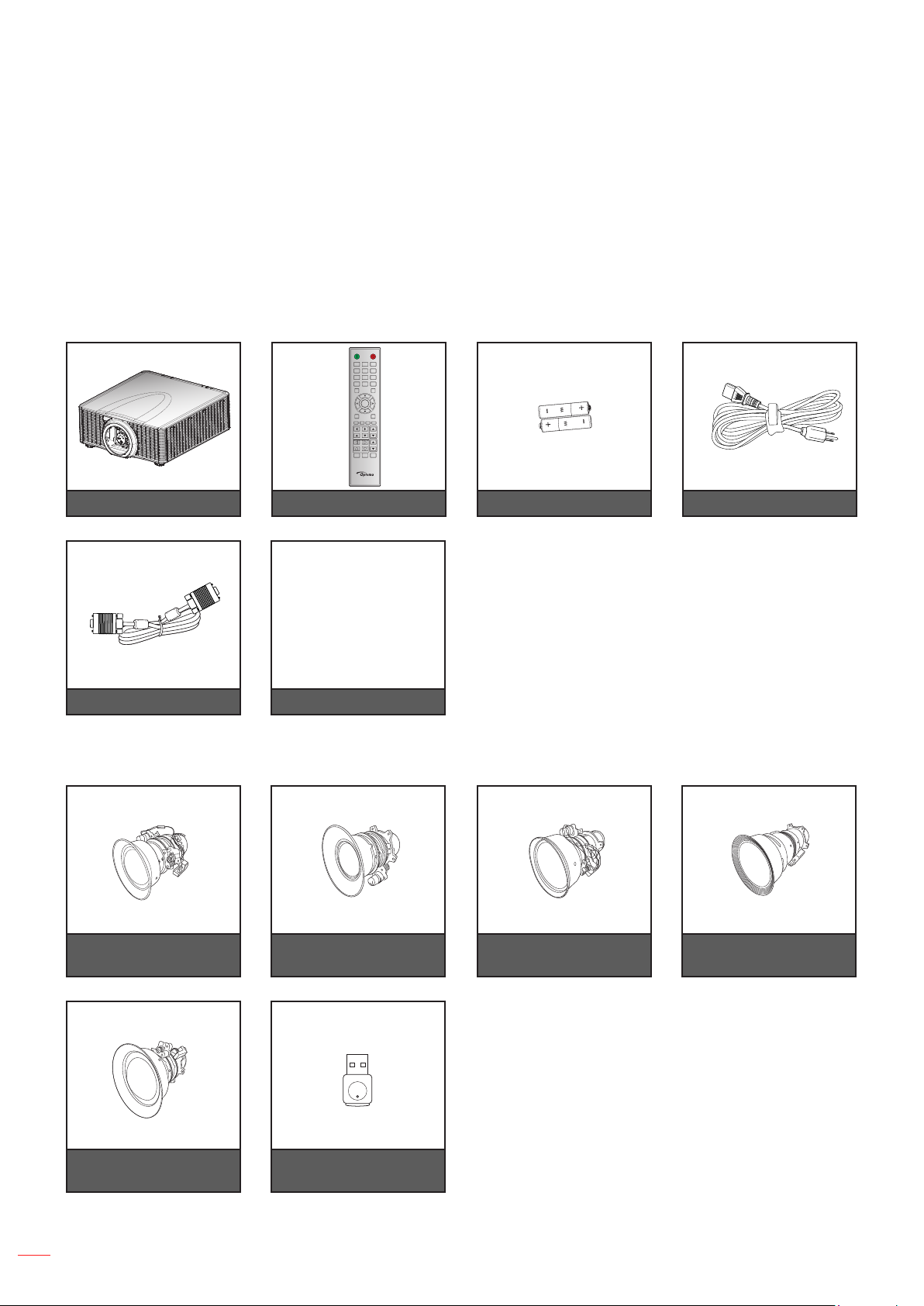
Carefully unpack and verify that you have the items listed below under standard accessories. Some of the items
under optional accessories may not be available depending on the model, specication and your region of
purchase. Please check with your place of purchase. Some accessories may vary from region to region.
The warranty card is only supplied in some specic regions. Please consult your dealer for detailed information.
Standard accessories
ON OFF
21 3
54 6
87 9
Mode
Info
0
Input
Auto
Enter
Menu Exit
Gamma Bright Cont. PIP
Focus
Lens H
Lens V
Zoom
Keystone H
Keystone V
Shutter
Hot Key
Pattern
(AV Mute)
Projector Remote control 2x AAA batteries Power lead
VGA cable
Optional accessories
Optional lens A01
(1.00-1.28)
CD User Manual
Warranty Card
Basic User Manual
Documentation
Optional lens A02
(1.28-1.61)
Optional lens A03
(1.60-3.07)
Optional lens A13
(3.04-5.78)
Optional lens A15
(0.79-1)
Wireless dongle
(WUSB Pro)
Note: Optional accessories vary depending on model, specication and region.
English
8
Page 9
INTRODUCTION
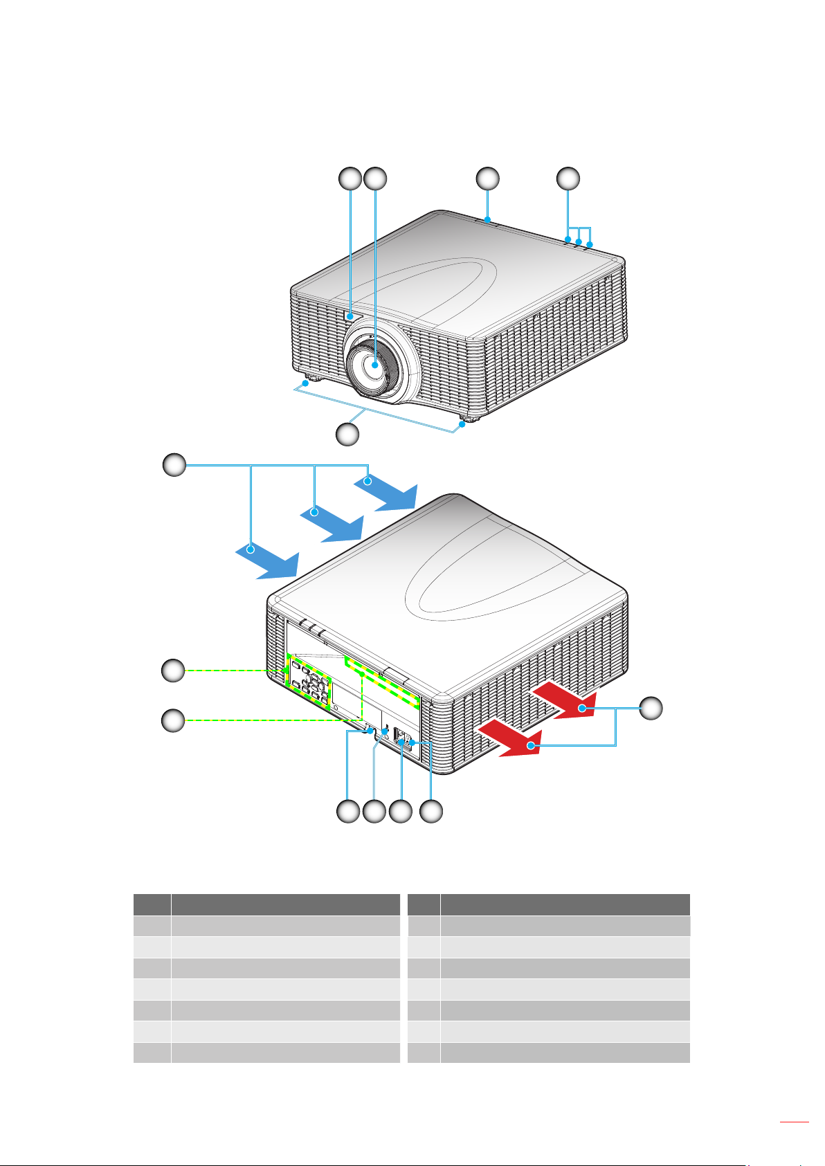
Product Overview
1 2
5
6
3 4
13
12
1011
Note: Do not block projector inlet or outlet air vents.
(*) optional accessory varies depending on model, specication, and region.
No Item No Item
1. Front IR Receiver 8. Power Switch
2. Lens 9. Power Socket
3. Top IR Receiver 10. Kensington
4. LED Status Indicators 11. Security Bar
5. Tilt-Adjustment Feet 12. Input / Output
6. Ventilation (inlet) 13. Keypad
7. Ventilation (outlet)
89
TM
Lock Port
7
English
9
Page 10
INTRODUCTION
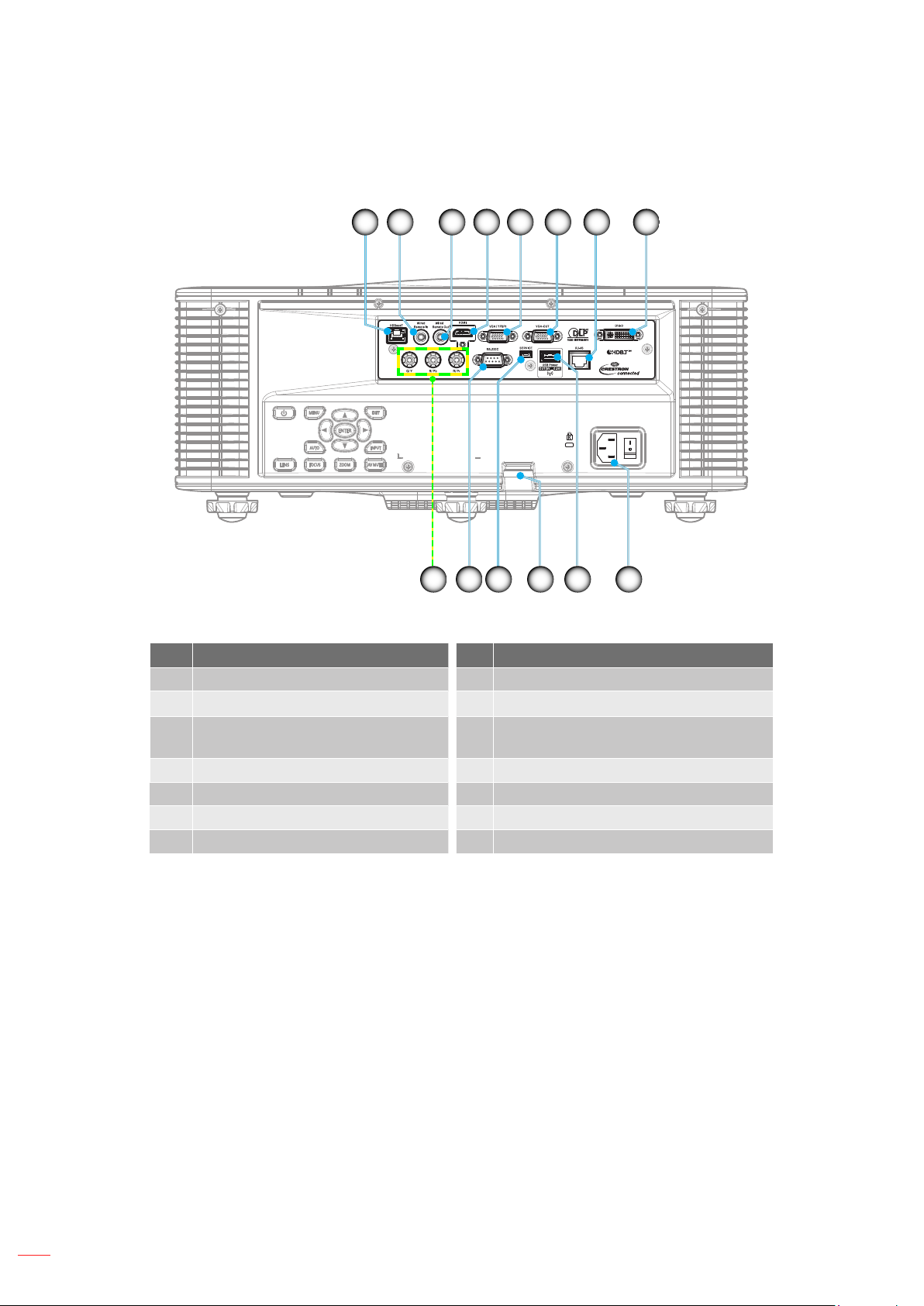
Connections
1 2 3 4 5 6 87
10121314 11
No Item No Item
1. HDBaseT Connector 8. DVI-D Connector
2. Remote IN Connector 9. Power Socket
3. Remote OUT Connector 10. USB Connector (support 5V, 0.5A) for
wireless dongle
4. HDMI Connector 11. Security Bar
5. VGA IN / YPbPr Connector 12. SERVICE Connector
6. VGA OUT Connector 13. RS-232C Connector
7. RJ-45 Connector 14. Component IN Connector
9
10
English
Page 11
INTRODUCTION
Keypad
1 2 3 4 5
1011
No Item No Item
1.
2.
3.
4.
5.
6.
Power
Menu
Enter
Exit
Input
AV Mute
Four Directional Select Keys
7.
Zoom
8.
Focus
9.
Auto
10.
Lens
11.
6789
English
11
Page 12
INTRODUCTION
Remote control
ON OFF
1
16
21 3
2
3
4
5
6
7
8
9
10
11
12
13
14
54 6
87 9
Info
Auto
Enter
Menu Exit
Gamma Bright Cont. PIP
Lens H
Lens V
Keystone H
Keystone V
Shutter
(AV Mute)
0
Hot Key
Mode
Input
Focus
Zoom
Pattern
17
18
19
20
21
22
23
24
15
No Item No Item No Item
1. Power On 9. Bright 17. Mode
Number Keys
2.
Lens H 18. Input
10.
3. Info 11. Lens V 19. Exit
4. Auto 12. Keystone H 20. PIP
5. Enter 13. Keystone V 21. Cont.
6. Four Directional Select Keys 14. Shutter (AV Mute) 22. Focus
7. Menu 15. Hot Key 23. Zoom
8. Gamma 16. Power Off 24. Pattern
12
English
Page 13
SETUP AND INSTALLATION
Installing the projection lens
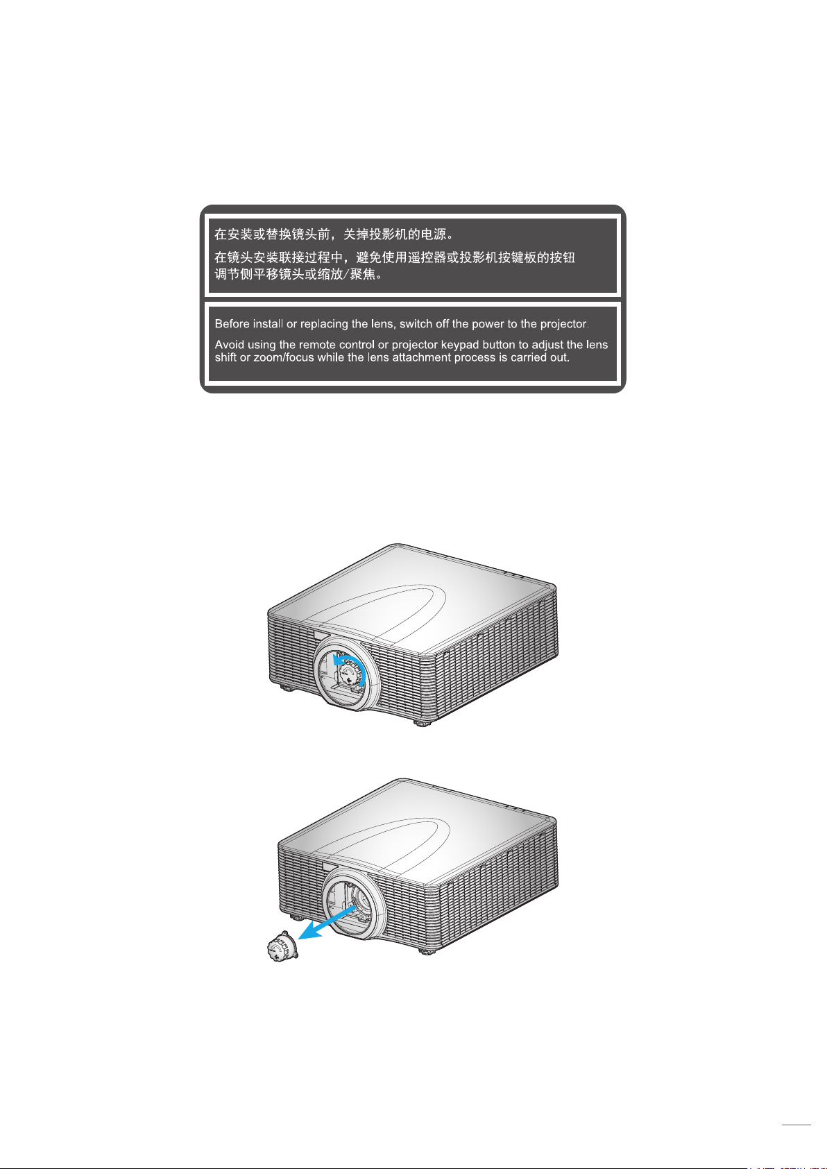
Before setting up the projector, install the projection lens on the projector.
IMPORTANT!
Make sure the projector is properly turned off before installing the lens.
During lens installation, do not adjust the lens shift, zoom, or focus either using the remote control or
the projector keypad.
Procedure:
1. Rotate the lens cap counterclockwise.
2. Remove the lens cap.
English
13
Page 14
SETUP AND INSTALLATION
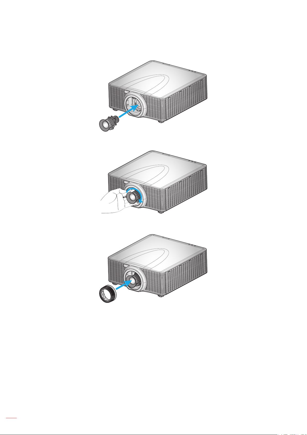
3. Install the lens onto the projector.
4. Rotate the lens clockwise to lock the lens in place.
5. Firmly install the lens ring onto the lens.
Note: The lens ring is compatible with the following lens modules: A01 (1.00-1.28), A02 (1.28-1.61), A03 (1.60-
3.07), and A13 (3.04-5.78).
14
English
Page 15
SETUP AND INSTALLATION
Adjusting the projector position
When you select a position for the projector, consider the size and shape of your screen, the location of your power
outlets, and the distance between the projector and the rest of your equipment. Follow these general guidelines:
Position the projector on a at surface at a right angle to the screen. The projector (with the standard
lens) must be at least 3 feet (0.9m) from the projection screen.
Position the projector to the desired distance from the screen. The distance from the lens of the
projector to the screen, the zoom setting, and the video format determine the size of the projected
image.
For the xed short lens, the image exits at a default angle. However, the lens shift feature makes the
image offset variable.
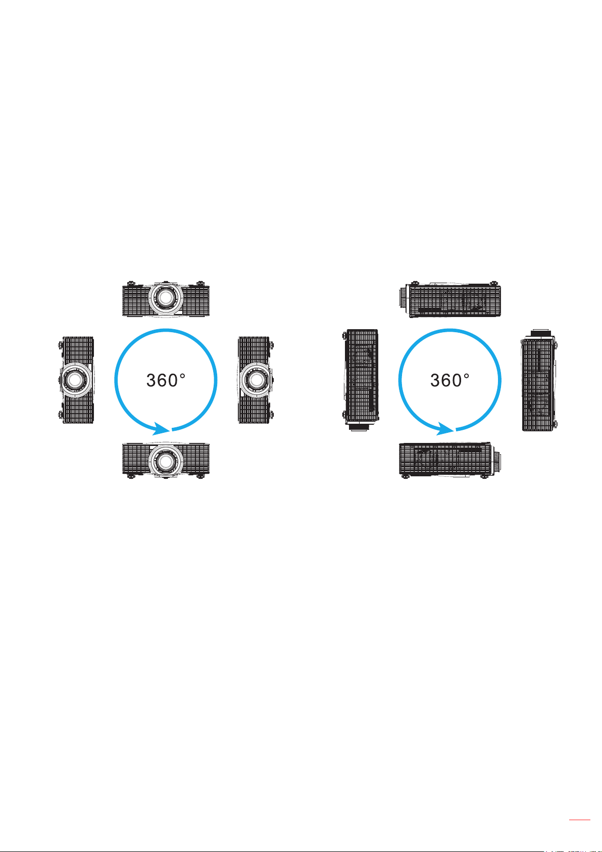
360 degree free orientation operation
English
15
Page 16
SETUP AND INSTALLATION
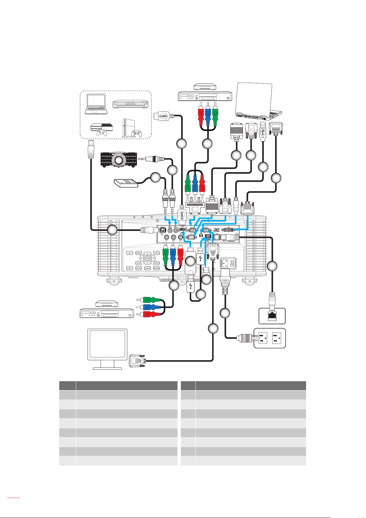
Connecting sources to the projector
4 5
MOLEX
6 7
3
2
1
15
13
5
14
11
12
8
9
10
16
No Item No Item
1. CAT5e/6/6A Cable 9. DVI-D Cable
2. Wired Remote-In Cable 10. RJ-45 Cable
3. Wired Remote-Out Cable 11. Power Cord
4. HDMI Cable 12. VGA-Out Cable
5. RCA Component Cable 13. Wireless (Wi-Fi) Dongle
6. VGA-In Cable 14. USB Power Cable
7. RS-232C Cable 15. HDMI Dongle
8. USB Cable (mouse control)
English
Page 17
SETUP AND INSTALLATION
Hot Key
Shutter
(AV Mute)
Pattern
Focus
Lens H
Lens V
Keystone H
Keystone V
Zoom
Adjusting the projector image
Image height
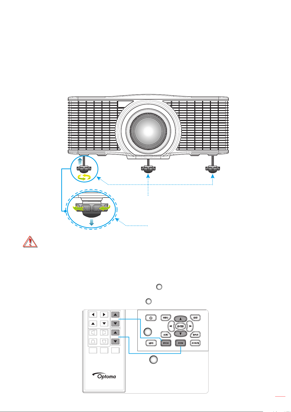
The projector is equipped with elevator feet for adjusting the image height.
1. Locate the adjustable foot you wish to adjust on the underside of the projector.
2. Rotate the adjustable foot clockwise or counterclockwise to raise or lower the projector.
Warning:
The feet of projector are not removable. Please do not screw out the feet of projector. The adjustable
Zoom and focus
To adjust the image size, press the Zoom button (
To adjust the focus, press the Focus button (
Tilt-Adjustment Feet
Tilt-Adjustment Ring
height of the elevator feet could be raised up to 45mm.
A
size.
B
) until the image is sharp and legible.
B
) to increase or decrease the projected image
A
English
17
Page 18
SETUP AND INSTALLATION
Remote setup
Installing / replacing the batteries
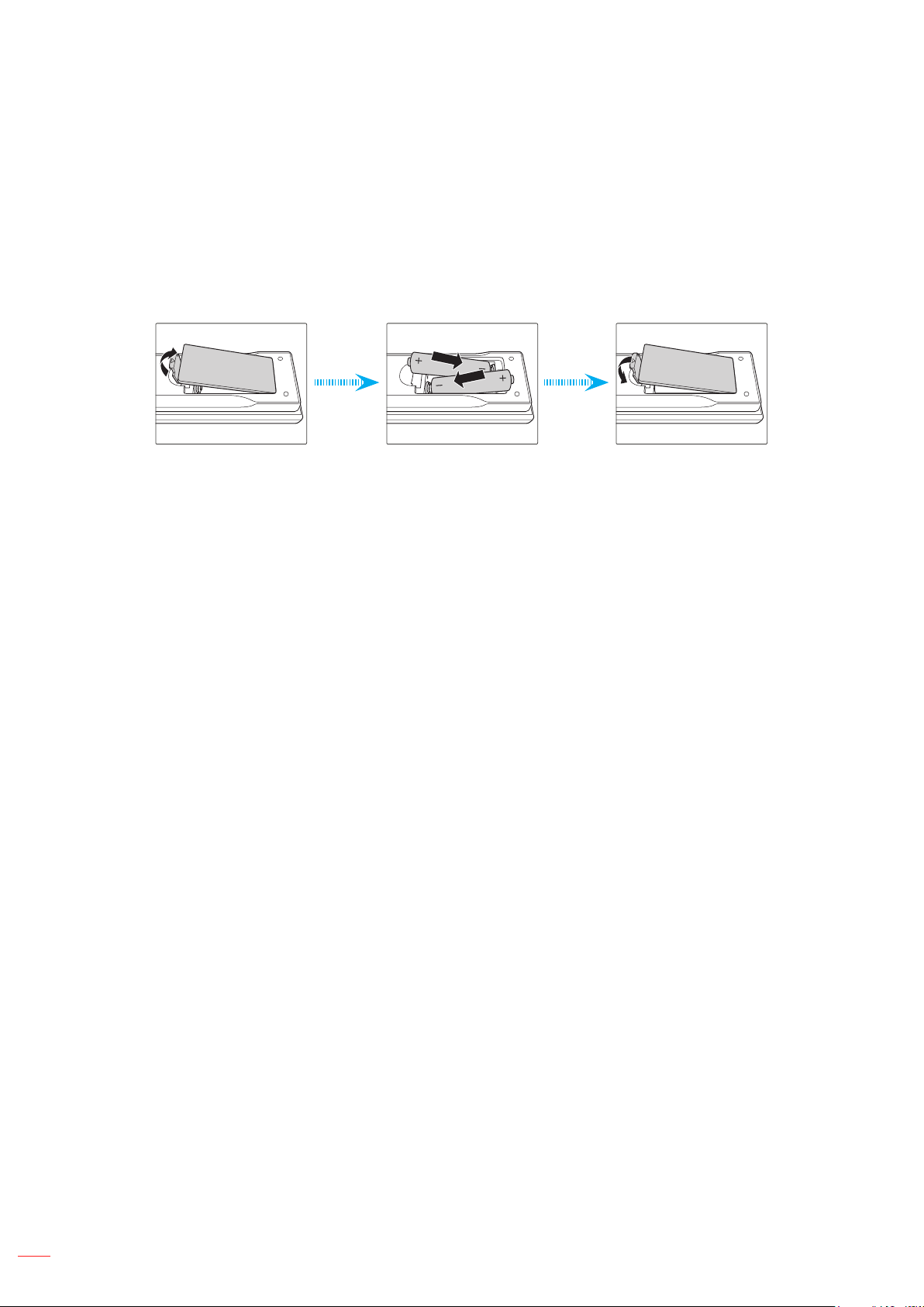
Two AAA size batteries are supplied for the remote control.
1. Remove the battery cover on the back of the remote control.
2. Insert AAA batteries in the battery compartment as illustrated.
3. Replace back cover on remote control.
Note: Replace only with the same or equivalent type batteries.
CAUTION
Improper use of batteries can result in chemical leakage or explosion. Be sure to follow the instructions below.
Do not mix batteries of different types. Different types of batteries have different characteristics.
Do not mix old and new batteries. Mixing old and new batteries can shorten the life of new batteries or
cause chemical leakage in old batteries.
Remove batteries as soon as the are depleted. Chemicals that leak from batteries that come in contact
with skin can cause a rash. If you nd any chemical leakage, wipe thoroughly with a cloth.
The batteries supplied with this product may have a shorter life expectancy due to storage conditions.
If you will not be using the remote control for an extended period of time, remove the batteries.
When you dispose of the batteries, you must obey the law in the relative area or country.
Effective range
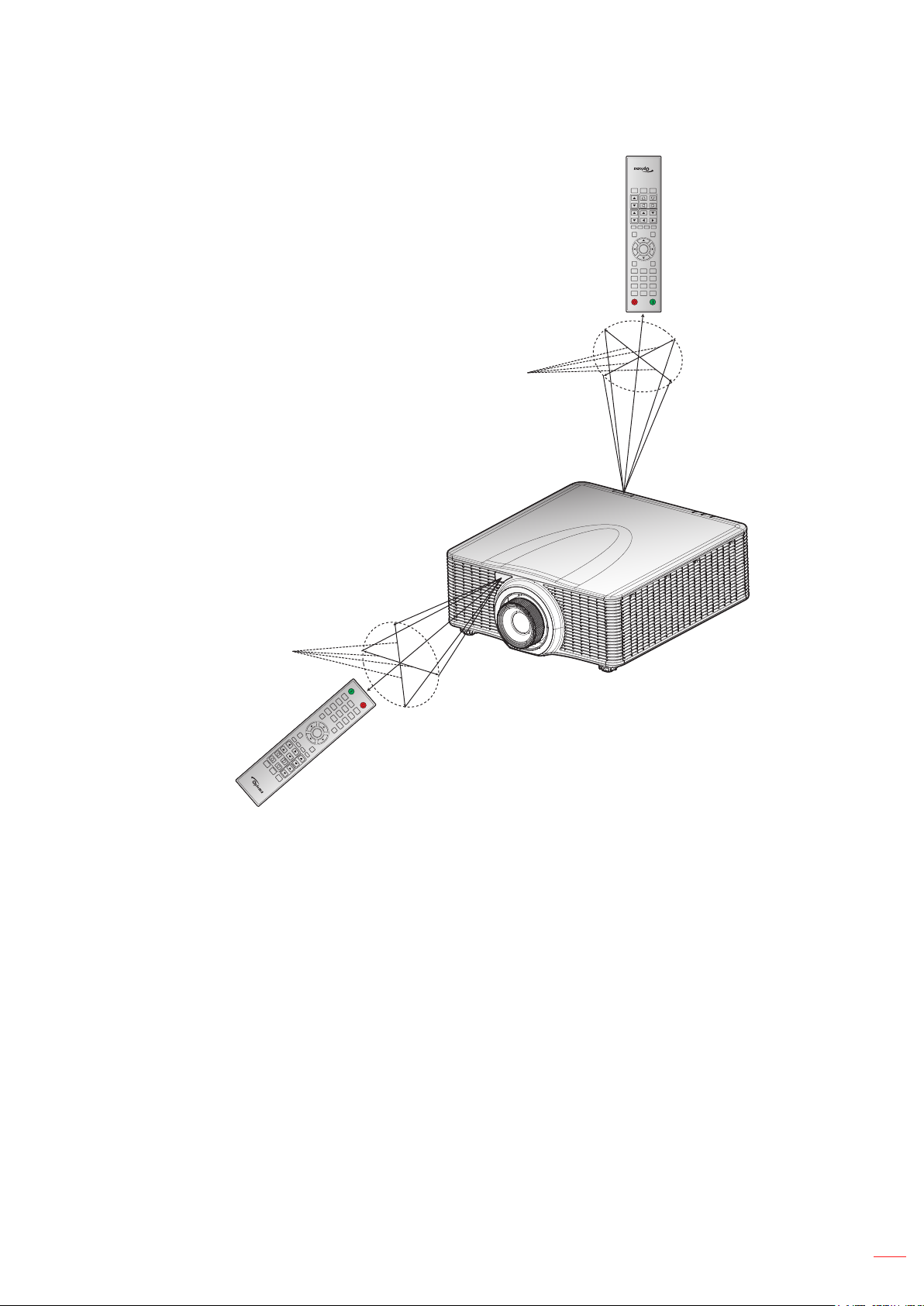
Infra-Red (IR) remote control sensors are located on the front and top sides of the projector. Ensure to hold the
remote control at an angle within ±30° (horizontally or vertically) to the projector's IR remote control sensor to
function correctly. The distance between the remote control and the sensor should not be longer than 10 meters
(32.8 feet).
Make sure that there are no obstacles between the remote control and the IR sensor on the projector
that might obstruct the infra-red beam.
Make sure the IR transmitter of the remote control is not being shined by sunlight or uorescent lamps
directly.
Please keep the remote controller away from uorescent lamps for over 2 m or the remote controller
might become malfunction.
18
If the remote control is closed to Inverter-Type uorescent lamps, it might become ineffective from time
to time.
If the remote control and the projector are within a very short distance, the remote control might
become ineffective.
When you aim at the screen, the effective distance is less than 5 m from the remote control to the
screen and reecting the IR beams back to the projector. However, the effective range might change
according to screens.
English
Page 19
SETUP AND INSTALLATION
Approx. ±30°
(AV Mute)
Pattern
Hot Key
Shutter
Keystone V
Zoom
Keystone H
Lens V
Focus
Lens H
Gamma Bright Cont. PIP
Menu Exit
Enter
Auto
Input
0
Info
Mode
87 9
54 6
21 3
ON OFF
Approx. ±30°
Keystone H
Keystone V
Shutter
(AV Mute)
Hot Key
ON
1
OFF
4
2
7
5
Info
3
8
Auto
6
0
9
Mode
Input
Enter
Menu
Gamma
Bright
Cont.
Lens H
Exit
PIP
Lens V
Focus
Zoom
Pattern
English
19
Page 20
USING THE PROJECTOR
ON OFF
21 3
Powering on / off the projector
or
Powering on
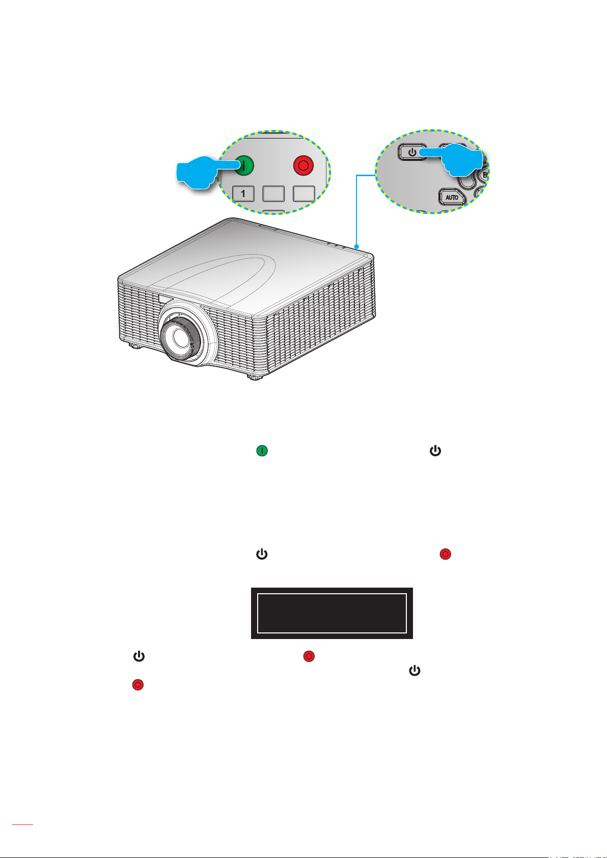
1. Securely connect the power lead and signal/source cable.
2. Set the Power switch to the “ON” position.
3. Turn on the projector by pressing “
The Status LED is Orange with a long blink.
Note: The rst time the projector is turned on, you will be prompted to select the preferred language, projection
orientation, and other settings.
Powering off
1. Turn off the projector by pressing “
A warning message will appear on the displayed image.
2. Press “ ” on the projector keypad or press “ ” on the remote control again to conrm, otherwise the
warning message will disappear after 10 seconds. When you press “ ” on the projector keypad or
press “ ” on the remote control for the second time, the projector will shut down.
” on the remote control or pressing “ ” on the projector keypad.
” on the projector keypad or pressing “ ” on the remote control.
Powering Off...
Press OFF key to Conrm
3. Set the Power switch to the “OFF” position.
4. Disconnect the power lead from the electrical outlet and the projector.
Note: It is not recommended that the projector is turned on immediately, right after a power off procedure.
English
20
Page 21
USING THE PROJECTOR
ON OFF
21 3
54 6
87 9
0
Info
Mode
Auto
Input
Enter
Selecting an input source
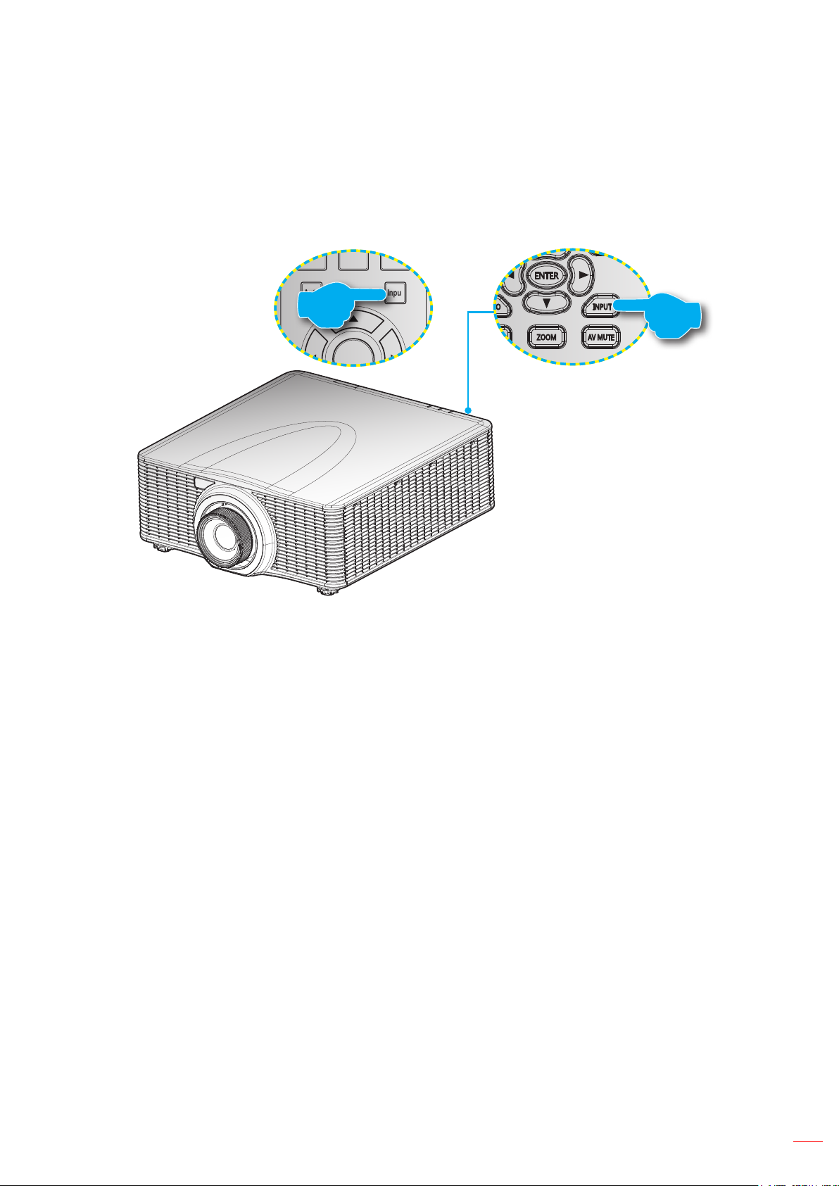
Turn on the connected source that you want to display on the screen, such as computer, notebook, video player,
etc. The projector will automatically detect the source. If multiple sources are connected, press the Input button on
the projector keypad or the remote control to select the desired input.
or
English
21
Page 22
USING THE PROJECTOR
Menu navigation and features
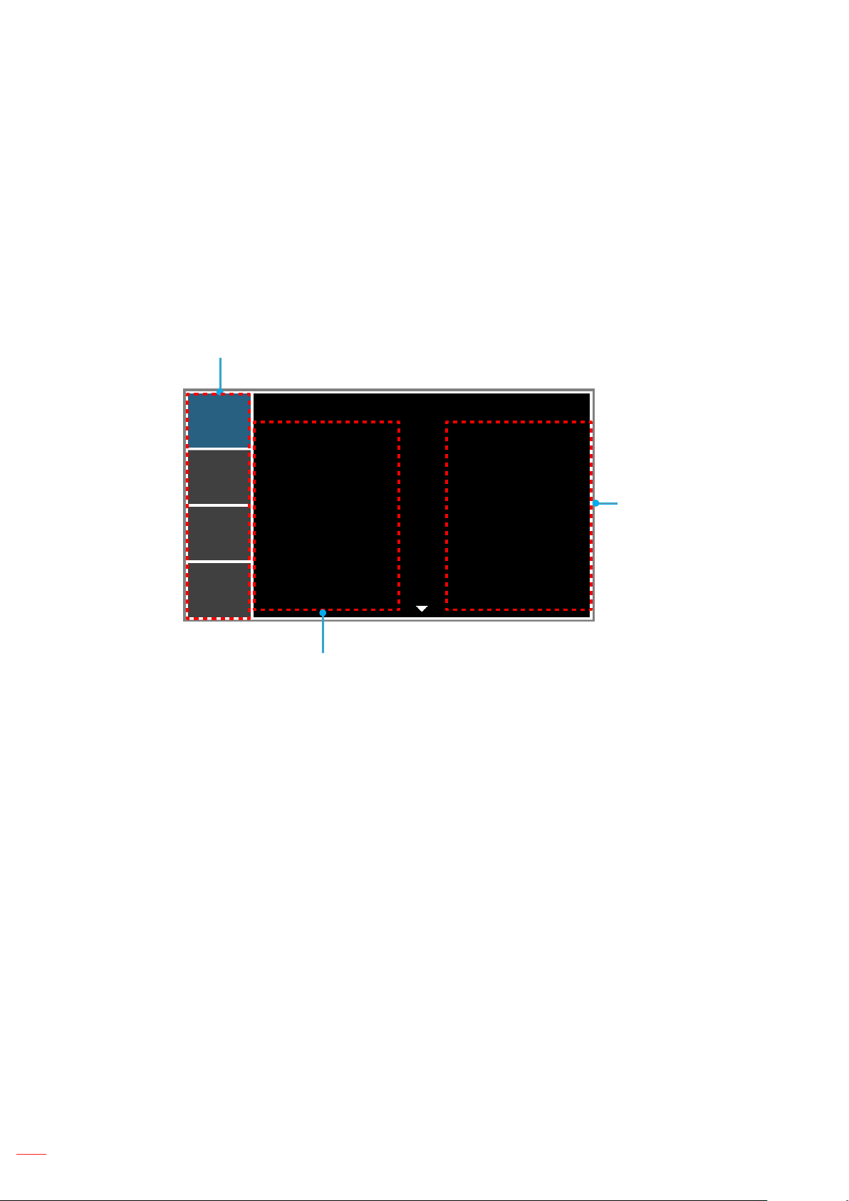
The projector has multilingual on-screen display menus that allow you to make image adjustments and change a
variety of settings. The projector will automatically detect the source.
1. To open the OSD menu, press "Menu" on the remote control or the projector keypad.
2. When OSD is displayed, use pqtu to navigate within the menu and adjust a setting up or down.
3. Press "Enter" to enter the submenu or conrm the selection/setting.
4. Press "Exit" to return to the previous menu or exit menus if at top level.
Main Menu
PICTURE
OUTPUT
SETUP
OPTION
Display Mode
Brightness
Contrast
Sharpness
Color
Tint
Phase
Frequency
Horz Position
Vert Position
Sub Menu
PICTURE
Presentation
50
50
2
50
50
50
50
50
50
Settings
22
English
Page 23
USING THE PROJECTOR
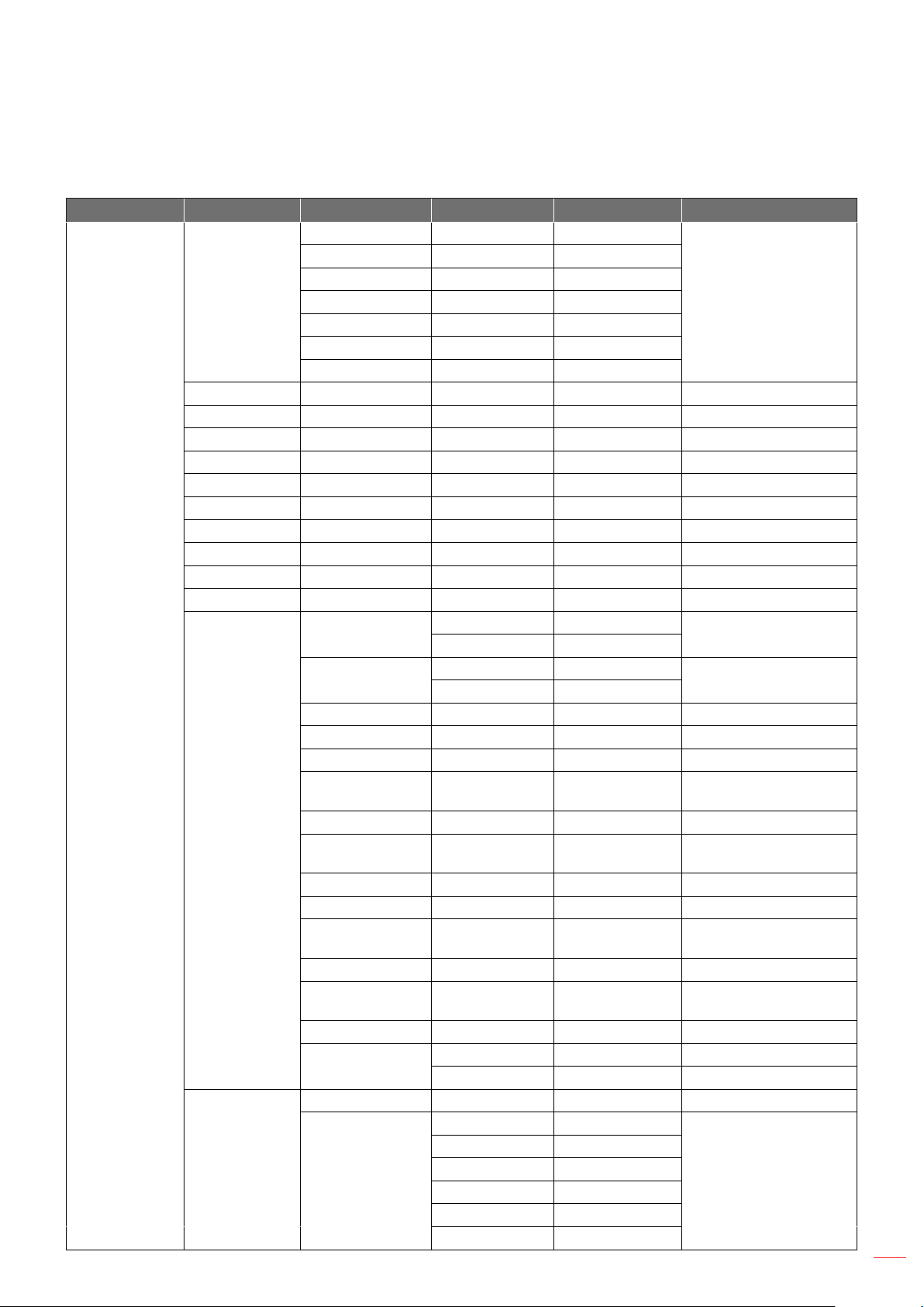
OSD Menu tree
Main Menu Sub Menu Sub Menu 2 Sub Menu 3 Sub Menu 4 Values
Presentation
Video
Bright
Display Mode
Brightness 0 ~ 100 50
Contrast 0 ~ 100 50
Sharpness 0 ~ 4 2
Color 0 ~ 100 50
Tint 0 ~ 100 50
Phase 0 ~ 100 50
Frequency 0 ~ 100 50
Horz Position 0 ~ 100 50
Vert Position 0 ~ 100 50
Auto Image
PICTURE
Color Matching
Advanced
DICOM SIM
Blending
User
Save to User
Enable
Auto Test Pattern
Red Part of Red 0 - 1000 1000
Green Part of Red 0 - 1000 0
Blue Part of Red 0 - 1000 0
Green Part of
Green
Red Part of Green 0 - 1000 0
Blue Part of
Green
Blue Part of Blue 0 - 1000 1000
Red Part of Blue 0 - 1000 0
Green Part of
Blue
Red Part of White 0 - 1000 1000
Green Part of
White
Blue Part of White 0 - 1000 1000
Reset to Default
White Peaking 0 - 100 By source set
Gamma
Off
On
Off
On
0 - 1000 1000
0 - 1000 0
0 - 1000 0
0 - 1000 1000
Yes
No
VIdeo
Film
Bright
CRT
DICOM
Gamma 2.2
By source set
Off
On
By source set
English
23
Page 24
USING THE PROJECTOR
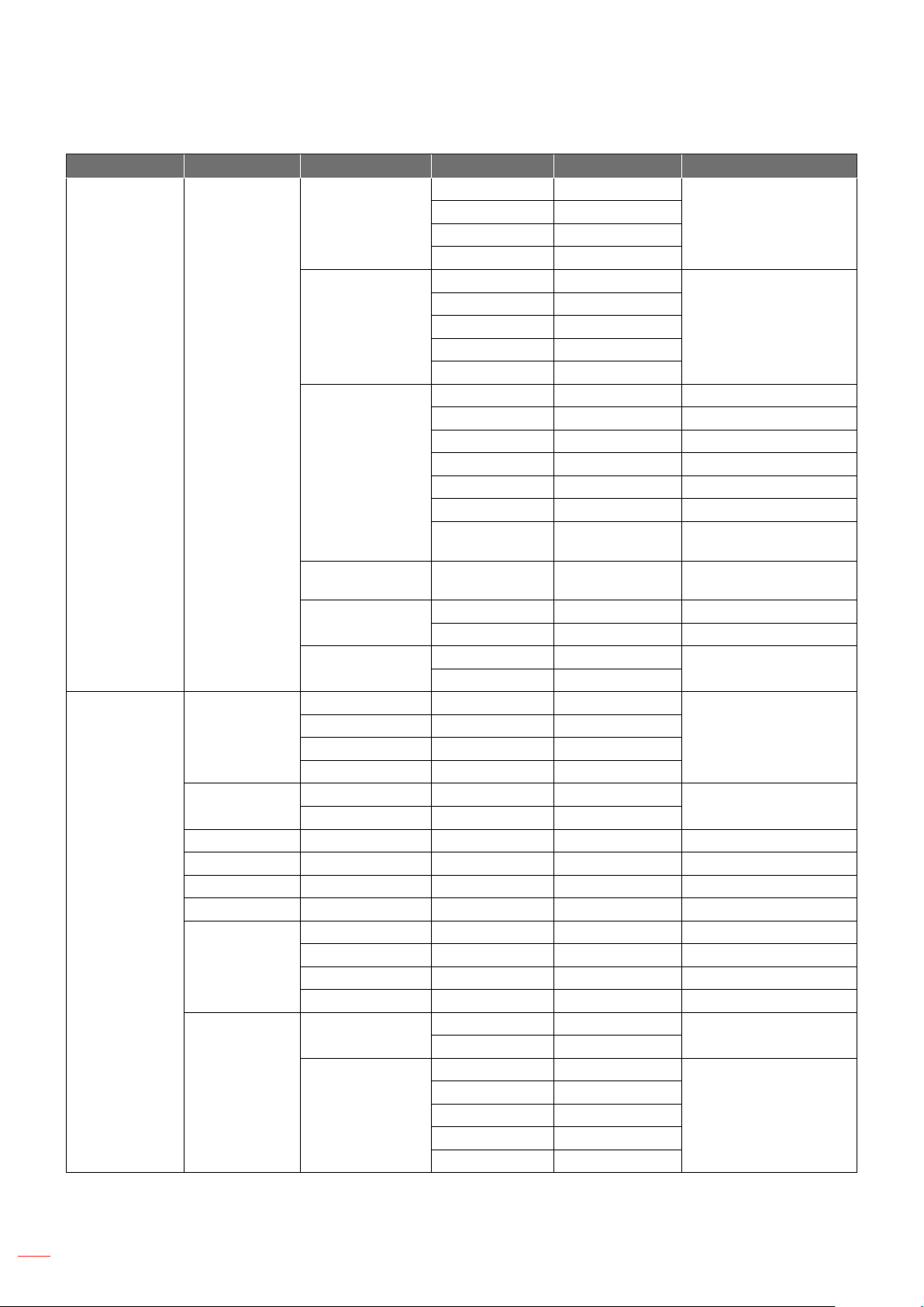
Main Menu Sub Menu Sub Menu 2 Sub Menu 3 Sub Menu 4 Values
Warmest
Warm
Cool
Bright
RGB
REC709
REC601
RGB Video
Auto
Red Gain 0 ~ 100 50
Green Gain 0 ~ 100 50
Blue Gain 0 ~ 100 50
Red Offset 0 ~ 100 50
Green Offset 0 ~ 100 50
Blue Offset 0 ~ 100 50
Reset RGB
Gain/Offset
0 ~ 2 1
Off
On
Off
On
Off
On
VGA
HDMI
Component
HDBaseT
DVI-D
By source set
Auto
On
Auto
By source set
Off
VGA
PICTURE Advanced
Aspect Ratio
Overscan
H Digital Zoom 50% ~ 400% 100
V Digital Zoom 50% ~ 400% 100
H Digital Shift 0 ~ 100 50
V Digital Shift 0 ~ 100 50
OUTPUT
Image Warping
PIP/PBP
Color
Temperature
Color Space
Color Settings
Color
Enhancement
Film Mode
Extreme Black
Auto
4:3
16:10
Native
Off
On
H Keystone 0 ~ 40 20
V Keystone 0 ~ 40 20
H Pincushion 0 ~ 100 50
V Pincushion 0 ~ 100 50
PIP/PBP Enable
Main Source
24
English
Page 25
USING THE PROJECTOR
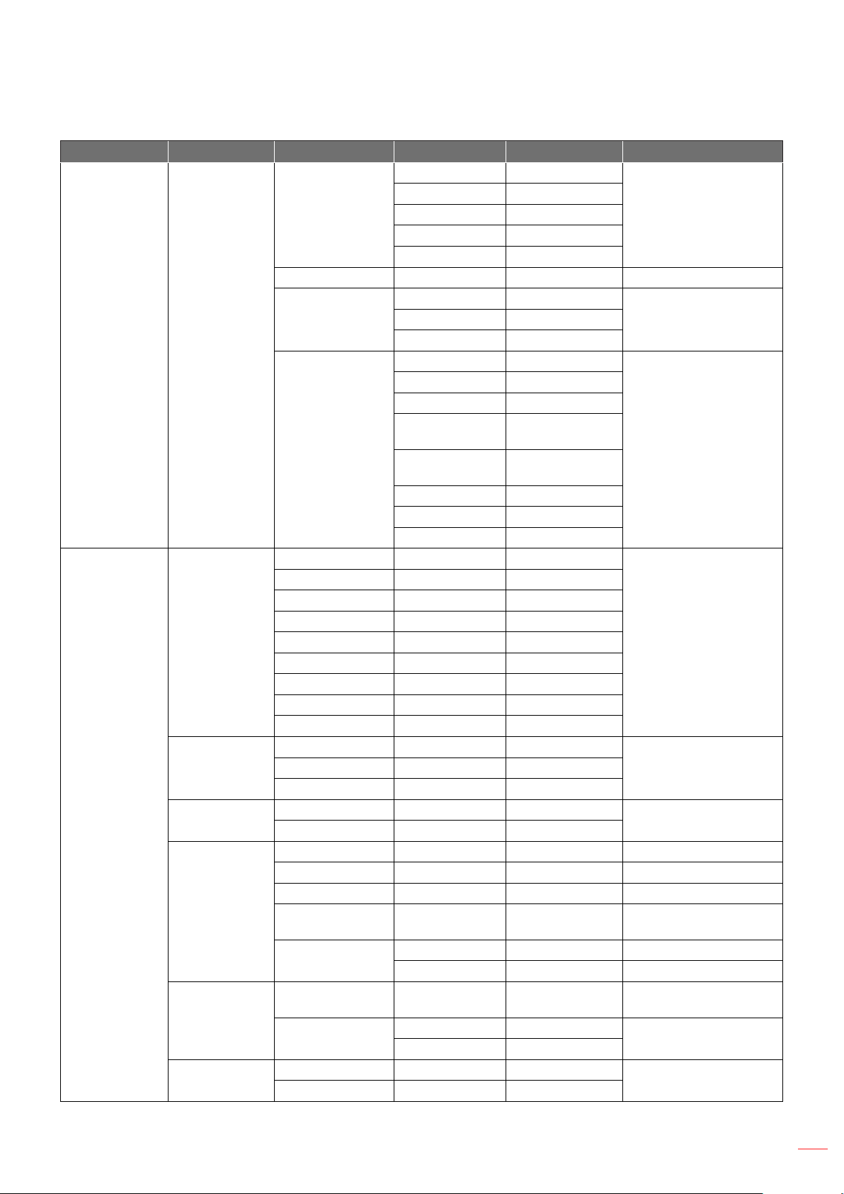
Main Menu Sub Menu Sub Menu 2 Sub Menu 3 Sub Menu 4 Values
VGA
HDMI
Component
HDBaseT
DVI-D
Small
Large
PBP, Main Left
PBP, Main Top
PBP, Main Right
PBP, Main
Bottom
PIP-Bottom
Right
PIP-Bottom Left
PIP-Top Left
PIP-Top Right
Yes/No (Dialog
box)
No
Yes
0 ~ 9 0
Off
On
LargeMedium
English
AutoOn
Off
On
On
OUTPUT PIP/PBP
Language
Ceiling Mount
SETUP
Rear Projection
Lens Function
Menu
Preferences
Keypad LED
Settings
Sub Source
Swap
Size
Layout
English
French
Spanish
German
Italian
Russian
Chinese Simpied
Japanese
Korean
Off
Auto
Off
On
Focus
Zoom
Lens Shift
Lens Calibration
Lens Lock
Menu
Transparency
Show Messages
Off
On
English
25
Page 26
USING THE PROJECTOR
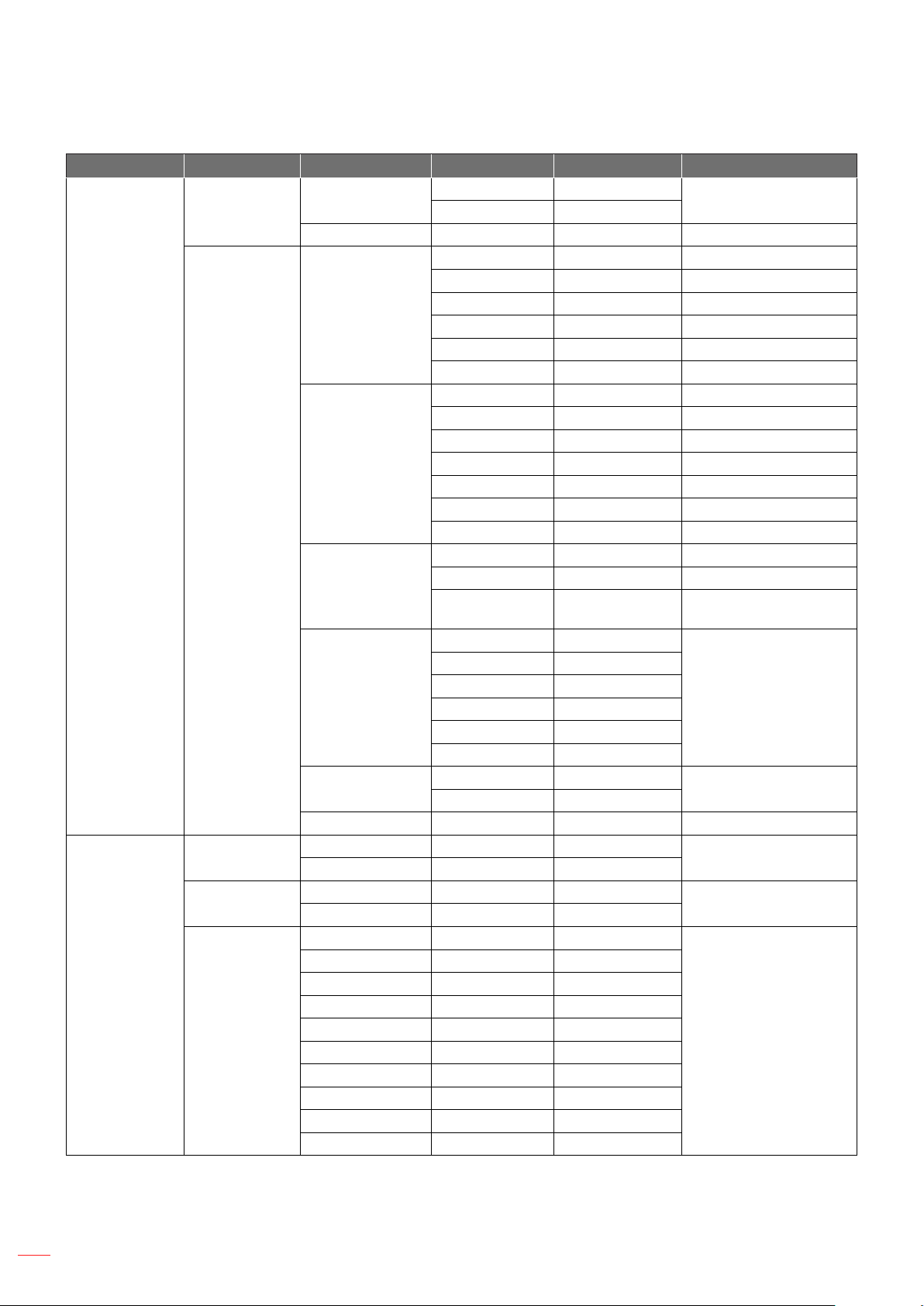
Main Menu Sub Menu Sub Menu 2 Sub Menu 3 Sub Menu 4 Values
SETUP
OPTION
Pin
Communications
Auto Source
High Altitude
Test Pattern
Pin Protect
Change PIN
LAN
WLAN
Network
Serial Port Baud
Rate
Serial Port Path
Projector Address 0 - 9 0
Off
On
Off
On
Off
Grid
Red
Green
Blue
Yellow
Magenta
Cyan
White
Black
Off
On
DHCP by set
IP Address by set
Subnet Mask by set
Default Gateway by set
MAC Address
Apply by set
Enable by set
Start IP by set
End IP by set
Subnet Mask by set
Default Gateway by set
MAC Address by set
SSID by set
Projector Name by set
Restart Network
Network Factory
Reset
9600
14400
19200
38400
57600
115200
RS232
HDBaseT
Off
PIN default : 12345
19200
RS232
On
Off
Off
26
English
Page 27
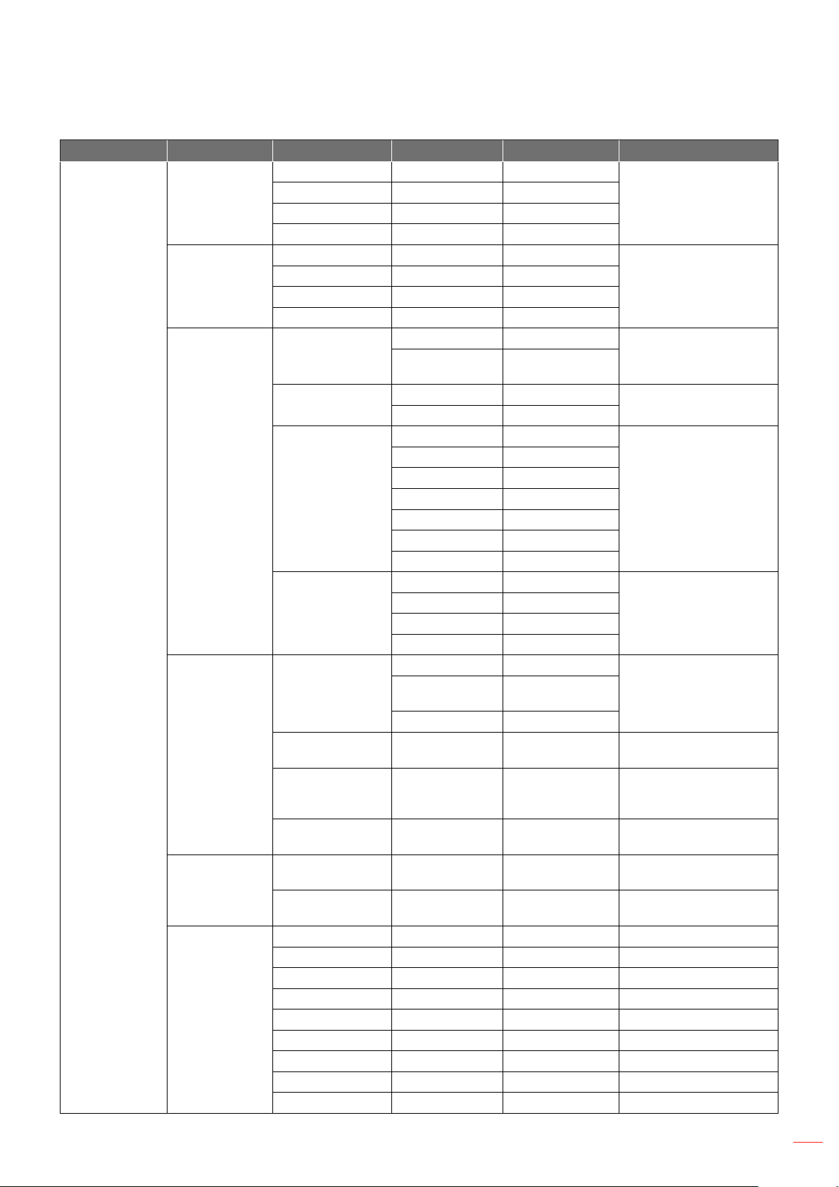
USING THE PROJECTOR
Main Menu Sub Menu Sub Menu 2 Sub Menu 3 Sub Menu 4 Values
Logo
Background
Color
Hot-Key settings
Power Settings
OPTION
Light Source
Settings
Light Sensor
Information
Blue
Black
White
Blank Screen
Aspect Ratio
Freeze Screen
Overscan
Standby Power
Mode
Direct Power On
Auto Power Off
Sleep Timer
Light Source
Mode
Constant Power
Settings
Constant
Luminance
Settings
Total Projector
Hours
Light Sensor
Calibration
Calibrated?
Model Name
Serial Number
Native Resolution
Firmware
Main Source
- Resolution
- Signal Format
- Pixel Clock
- Horz Refresh
Logo
Blank Screen
0.5W mode
Communication
mode
Off
On
No
5 Mins
10 Mins
15 Mins
20 Mins
25 Mins
30 Mins
No
2 Hours
4 Hours
6 Hours
Constant Power
Constant
Luminance
Eco Mode
0 - 10 10
0 - 10 7
(Display Yes/
No)
0.5W mode
Off
No
No
Constant Power
English
27
Page 28
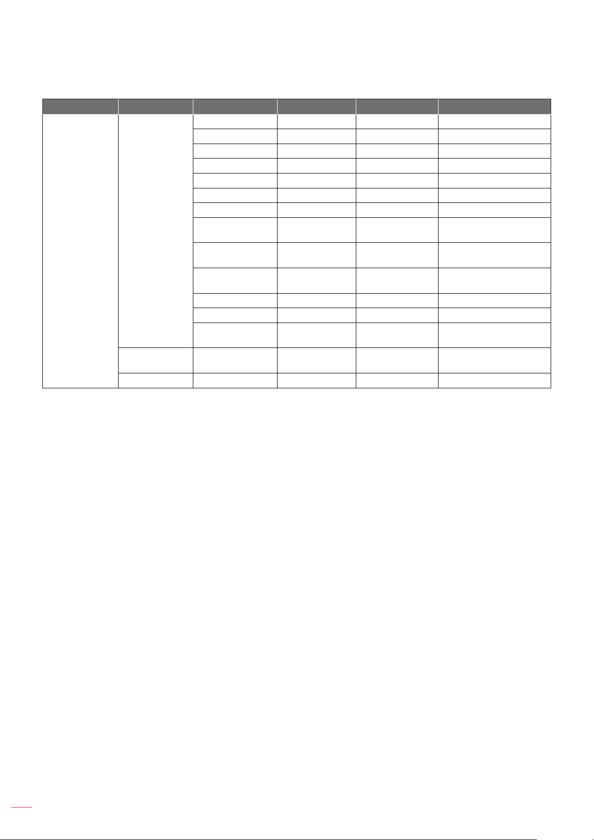
USING THE PROJECTOR
Main Menu Sub Menu Sub Menu 2 Sub Menu 3 Sub Menu 4 Values
- Vert Refresh
Sub Source
- Resolution
- Signal Format
- Pixel Clock
- Horz Refresh
- Vert Refresh
Information
OPTION
Factory Reset
Service
Light Source
Mode
Total Projector
Hours
Standby Power
Mode
IP Address
DHCP
System
Temperature
Yes/No (Dialog
box)
28
English
Page 29
USING THE PROJECTOR
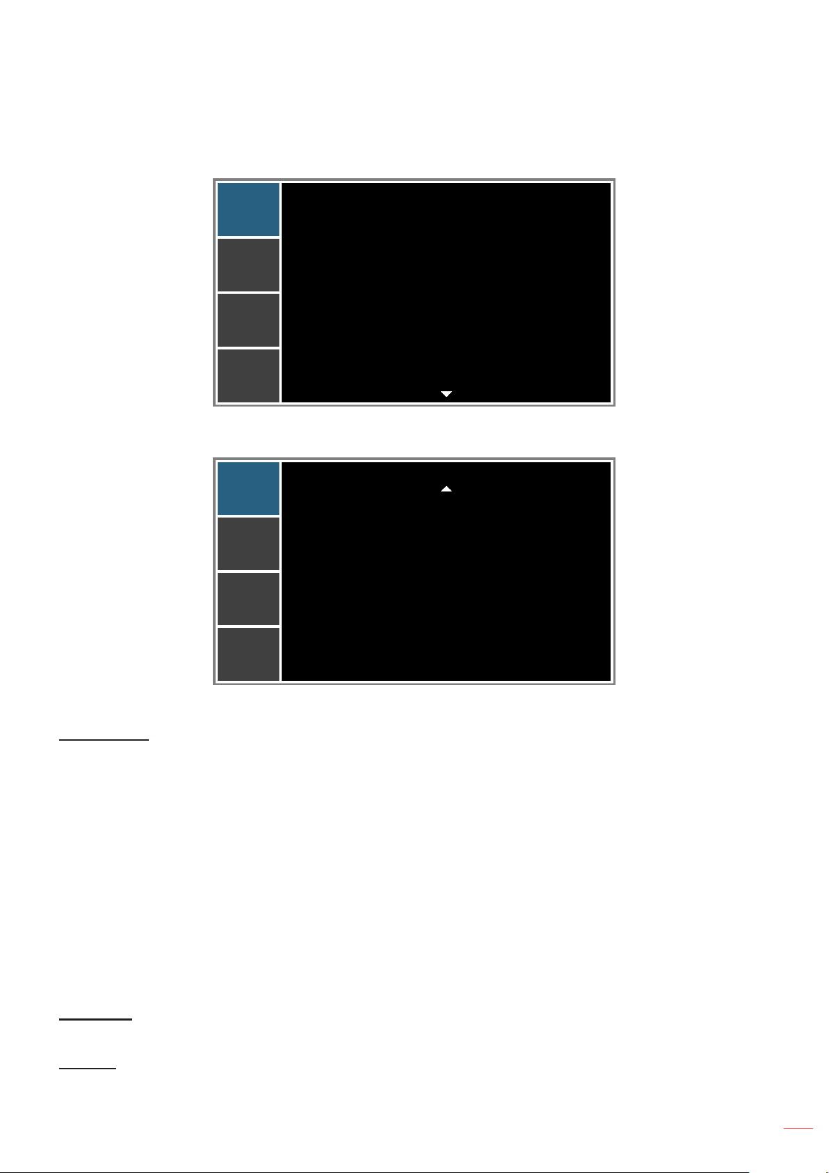
PICTURE menu
PICTURE
OUTPUT
SETUP
OPTION
PICTURE
OUTPUT
SETUP
Display Mode
Brightness
Contrast
Sharpness
Color
Tint
Phase
Frequency
Horz Position
Vert Position
Auto Image
Color Matching
Advanced
PICTURE
Presentation
50
50
2
50
50
50
50
50
50
PICTURE (1/2)
PICTURE
OPTION
PICTURE (2/2)
Display Mode
There are many factory presets optimized for various types of images.
Presentation: This mode is suitable for showing PowerPoint presentations when the projector is
connected to the PC.
Video: This mode is suitable for watching video.
Bright: Maximum brightness from PC input.
DICOM SIM: This mode can project a monochrome medical image such as an X ray radiography, MRI,
etc.
Blending: When using multiple projectors, this mode can eliminate the visible banding and create a
single bright, high resolution image across the screen.
User: Memorize user’s settings.
Save to User: Save the display mode settings in user prole.
Brightness
Adjust the brightness of the image.
Contrast
The contrast controls the degree of difference between the lightest and darkest parts of the picture.
English
29
Page 30

USING THE PROJECTOR
Sharpness
Adjust the sharpness of the image.
Color
Adjust a video image from black and white to fully saturated color.
Tint
Adjust the color balance of red and green.
Phase
Synchronize the signal timing of the display with the graphic card. If the image appears to be unstable or ickers,
use this function to correct it.
Frequency
Change the display data frequency to match the frequency of your computer’s graphic card. Use this function only
if the image appears ickering vertical lines.
Horz Position
Move the image right or left within the area of available pixels.
Vert Position
Move the image up or down within the area of available pixels.
Auto Image
Force the projector to reacquire and lock to the input signal. This is useful when signal quality is marginal.
Color Matching
Congure the color matching settings. Refer to “Color Matching menu” on page 31.
Advanced
Congure the advanced image settings. Refer to “Advanced menu” on page 32.
30
English
Page 31
USING THE PROJECTOR
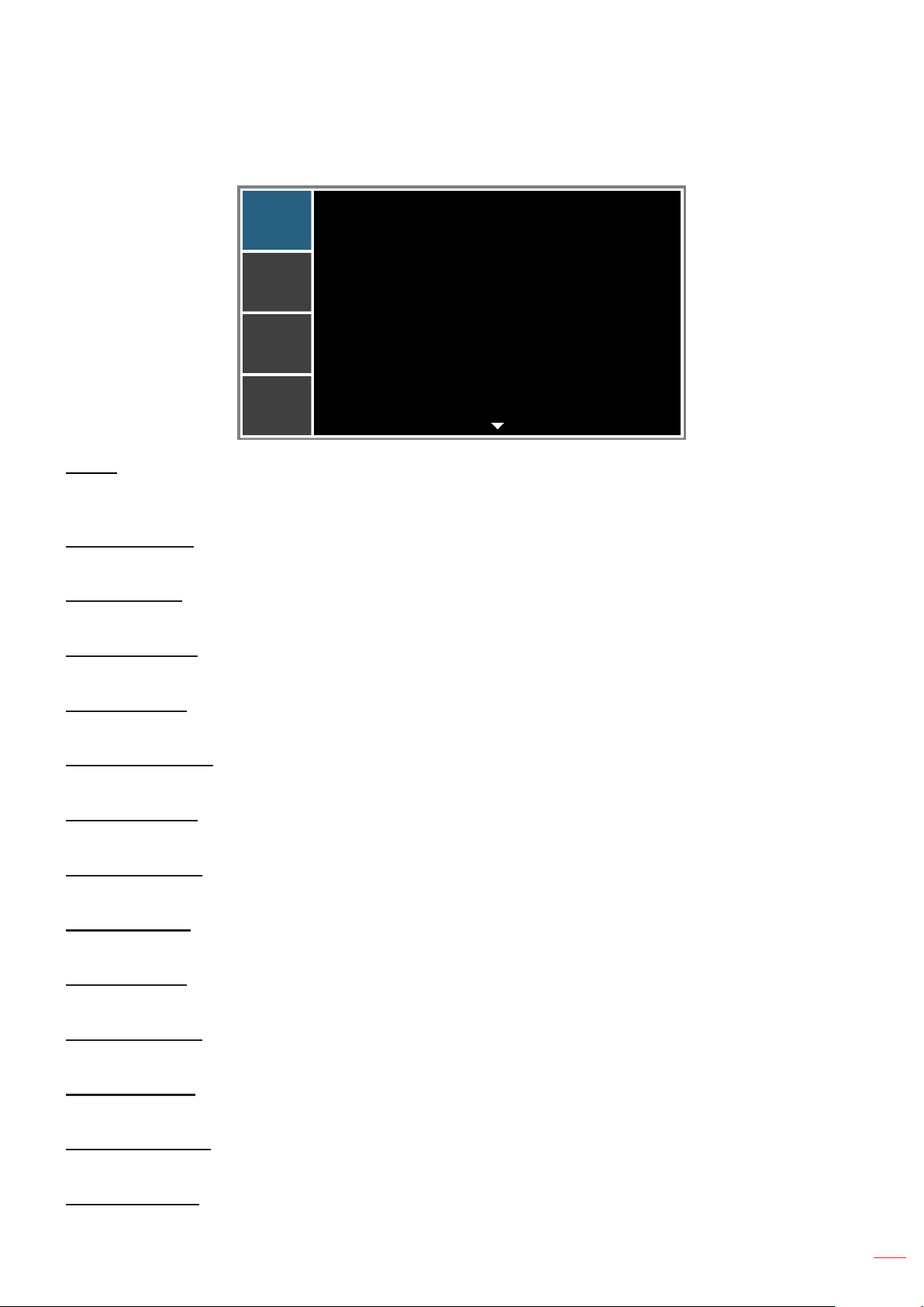
Color Matching menu
PICTURE
OUTPUT
SETUP
OPTION
Enable
Auto Test Pattern
Red Part of Red
Green Part of Red
Blue Part of Red
Green Part of Green
Red Part of Green
Blue Part of Green
Blue Part of Blue
Red Part of Blue
On
On
1000
0
0
1000
0
0
1000
0
Enable
You may require a unique color gamut (range) for a single projector or application, or you may need to precisely
match colors across multiple adjacent displays. Enable this feature to allow color matching.
Auto Test Pattern
Set to “On” to enable displaying an internal solid colored test pattern or set to “Off” to disable the auto test pattern.
Red Part of Red
Adjust the intensity of the red color component in red color. This will also affect the hue of the color.
Green Part of Red
Color Matching
Adjust the intensity of the green color component in red color. This will also affect the hue of the color.
Blue Part of Red
Adjust the intensity of the blue color component in red color. This will also affect the hue of the color.
Green Part of Green
Adjust the intensity of the green color component in green color. This will also affect the hue of the color.
Red Part of Green
Adjust the intensity of the red color component in green color. This will also affect the hue of the color.
Blue Part of Green
Adjust the intensity of the blue color component in green color. This will also affect the hue of the color.
Blue Part of Blue
Adjust the intensity of the blue color component in blue color. This will also affect the hue of the color.
Red Part of Blue
Adjust the intensity of the red color component in blue color. This will also affect the hue of the color.
Green Part of Blue
Adjust the intensity of the green color component in blue color. This will also affect the hue of the color.
Red Part of White
Adjust the intensity of the red color component in white color. This will also affect the hue of the color.
Green Part of White
Adjust the intensity of the green color component in white color. This will also affect the hue of the color.
Blue Part of White
Adjust the intensity of the blue color component in white color. This will also affect the hue of the color.
English
31
Page 32
USING THE PROJECTOR
Reset to Default
Select “Yes” to reset all the color matching adjustments to the factory defaults or select “No” to keep the current
values.
Advanced menu
PICTURE
OUTPUT
SETUP
OPTION
White Peaking
Gamma
Color Temperature
Color Space
Color Settings
Color Enhancement
Film Mode
Extreme Black
Advanced
100
VIdeo
Bright
Auto
0
On
On
White Peaking
(Video source only) Increase the brightness of whites that are near 100%.
Gamma
This allows you to set up gamma curve type. After the initial setup and ne tuning is completed, utilize the Gamma
adjustment steps to optimize your image output.
Video: for video or TV source.
Film: for home theater.
Bright: for emphasizing brightness.
CRT: for CRT monitor.
DICOM: for simulated DICOM.
Gamma 2.2: for specic PC / photo source.
Color Temperature
Select a color temperature from Warmest, Warm, Cool, or Bright.
Color Space
Select an appropriate color matrix type from RGB, REC709, REC601, RGB Video, or Auto.
Color Settings
Congure the brightness (gain) and contrast (offset) of an image.
Red Gain/Green Gain/Blue Gain/Red Offset/Green Offset/Blue Offset: Adjust the gain of the red,
green, or blue channel of the image. Adjust the offset of the red, green, or blue channel of the image. It
will affect the black and white.
Reset RGB Gain/Offset: Reset the gain and offset adjustments to the factory defaults.
Color Enhancement
Apply the color enhancement process.
32
English
Page 33

USING THE PROJECTOR
Film Mode
Control lm mode detection and determine whether the original source of the input video was lm or video.
Note: This function is available for interlaced video signals.
Extreme Black
Contrast can be increased by a dark content. Select “On” to let the projector will automatically improvement
contrast or select “Off” to disable this function.
English
33
Page 34
USING THE PROJECTOR
OUTPUT menu
PICTURE
OUTPUT
SETUP
OPTION
Aspect Ratio
Choose your desired aspect ratio.
Auto: Automatically selects the appropriate display format.
4:3: This format is for 4:3 input sources.
16:10: This format is for 16:10 aspect input sources, like HDTV and DVD enhanced for Wide screen
TV.
Native: This format displays the original image without any scaling.
Aspect Ratio
Overscan
H Digital Zoom
V Digital Zoom
H Digital Shift
V Digital Shift
Image Warping
PIP/PBP
OUTPUT
Auto
Off
100
100
50
50
Overscan
Remove noise around the image.
H Digital Zoom
Change the size of projector’s display area horizontally. If the display area has been resized by this setting, it can
be moved by changing the H Digital Shift and V Digital Shift settings.
V Digital Zoom
Change the size of projector’s display area vertically. If the display area has been resized by this setting, it can be
moved by changing the H Digital Shift and V Digital Shift settings.
H Digital Shift
Shift the display area horizontally if its size has been changed by the Digital Zoom setting.
V Digital Shift
Shift the display area vertically if its size has been changed by the Digital Zoom setting.
Image Warping
Congure the image warping settings. Refer to “Image Warping menu” on page 35.
PIP/PBP
Congure the PIP/PBP settings. Refer to “PIP/PBP menu” on page 36.
34
English
Page 35
USING THE PROJECTOR
Image Warping menu
PICTURE
OUTPUT
SETUP
OPTION
H Keystone
V Keystone
H Pincushion
V Pincushion
Image Warping
20
20
50
50
H Keystone
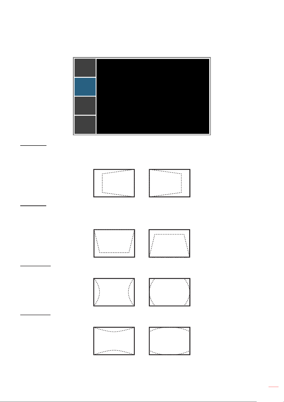
Adjust image distortion horizontally and make a squarer image. Horizontal keystone is used to correct a keystoned
image shape in which the left and right borders of the image are unequal in length. This is intended for use with
horizontally on-axis applications.
V Keystone
Adjust image distortion vertically and make a squarer image. Vertical keystone is used to correct a keystoned
image shape in which the top and bottom are slanted to one of the sides. This is intended when for use with
vertically on-axis applications.
H Pincushion
Adjust the pincushion horizontally and make a more square image.
V Pincushion
Adjust the pincushion vertically and make a more square image.
English
35
Page 36
USING THE PROJECTOR
PIP/PBP menu
PICTURE
OUTPUT
SETUP
OPTION
PIP/PBP Enable
Main Source
Sub Source
Swap
Size
Layout
On
VGA
DVI-D
Large
PBP, Main Left
PIP/PBP Enable
Toggle between displaying two sources at once (Main and PIP/PBP images) or one source only.
Main Source
From the list of active inputs, select one to be used as the main image.
Sub Source
From the list of active inputs, select one to be used as the sub image.
Swap
PIP/PBP
Swap the sources of main window and PIP/PBP window.
Size
Select the PIP/PBP size.
Layout
Set the location of the PIP/PBP image on the screen.
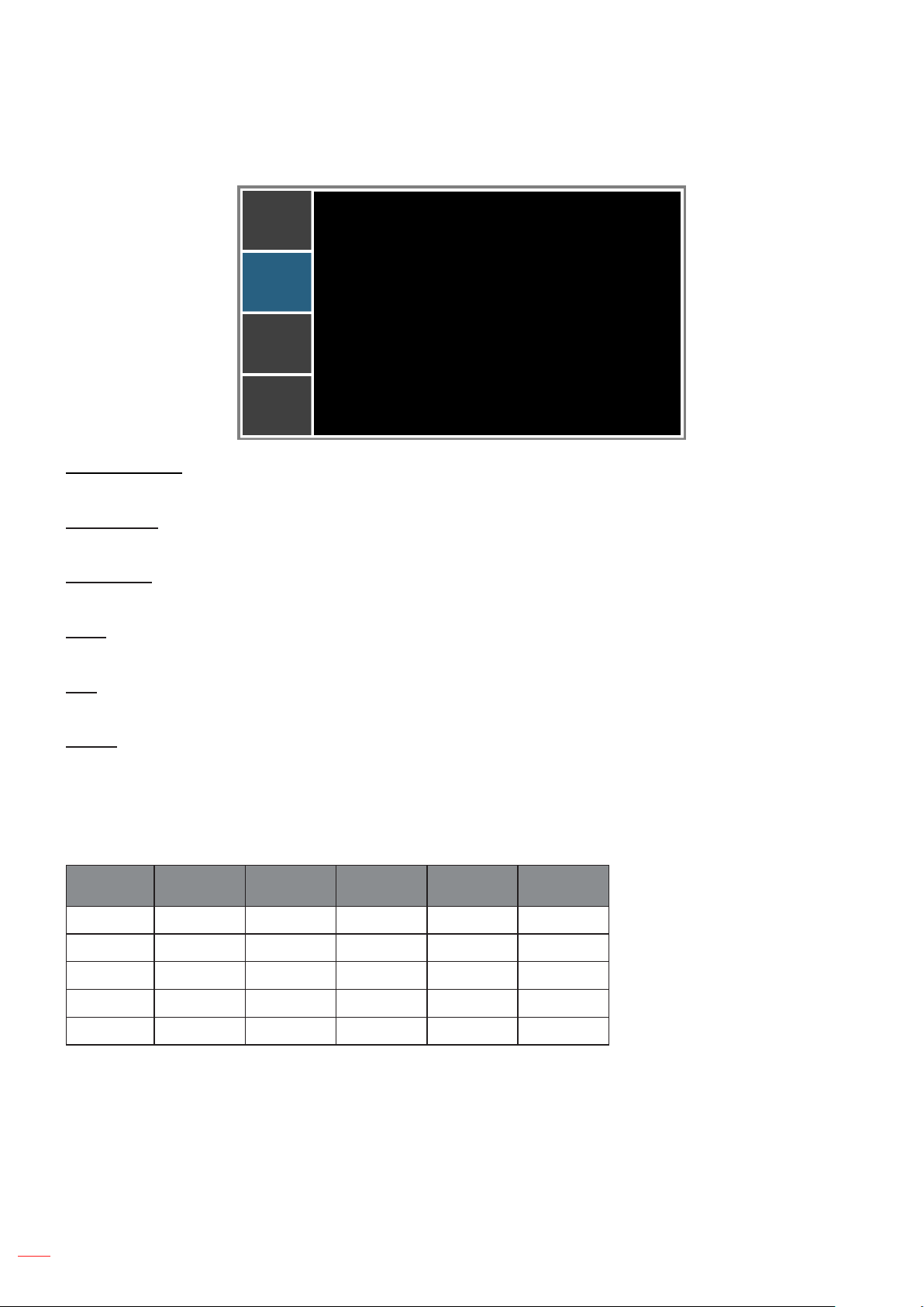
PIP/PBP Matrix
PIP/PBP compatibility table as described below:
PIP/PBP
Matrix
HDMI
VGA
Component
HDBaseT
DVI-D V V V V
Note:
1. Flashing lines may occur if the bandwidth of both inputs are too high, please try to reduce the resolution.
HDMI VGA Component HDBaseT DVI-D
— — — —
— — — —
— — — —
— — — —
V
V
V
V
—
36
2. Frame tearing may occur due to a difference in frame rate between the Main and the Sub picture, please
try to match the frame rate for each input.
English
Page 37
USING THE PROJECTOR
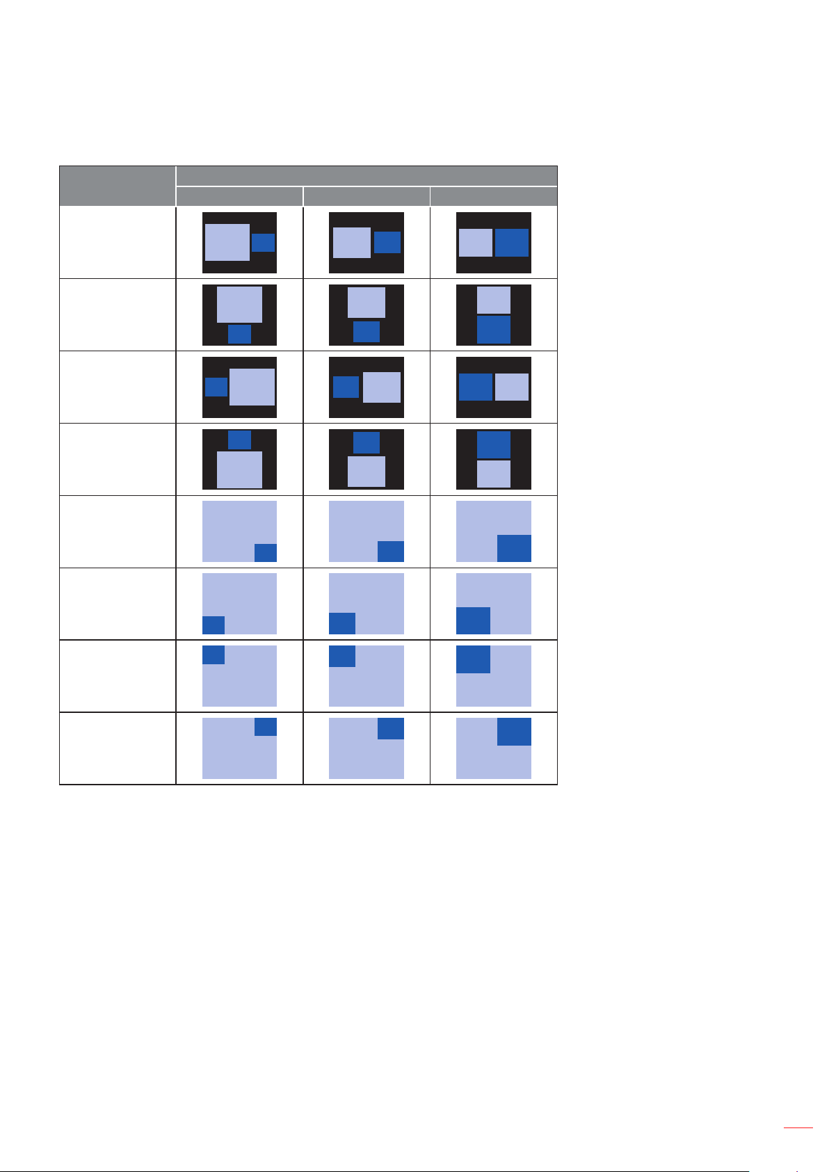
PIP/PBP layout and size table as described below:
PIP/PBP Layout
PBP, Main Left
PBP, Main Top
PBP, Main Right
PBP, Main Bottom
PIP-Bottom Right
PIP/PBP Size
Small Medium Large
P
P
P
P
P
P P
P
P P
P
P P
P
P
PIP-Bottom Left
PIP-Top Left
PIP-Top Right
P
P
P
P
P P
P P
P
English
37
Page 38
USING THE PROJECTOR
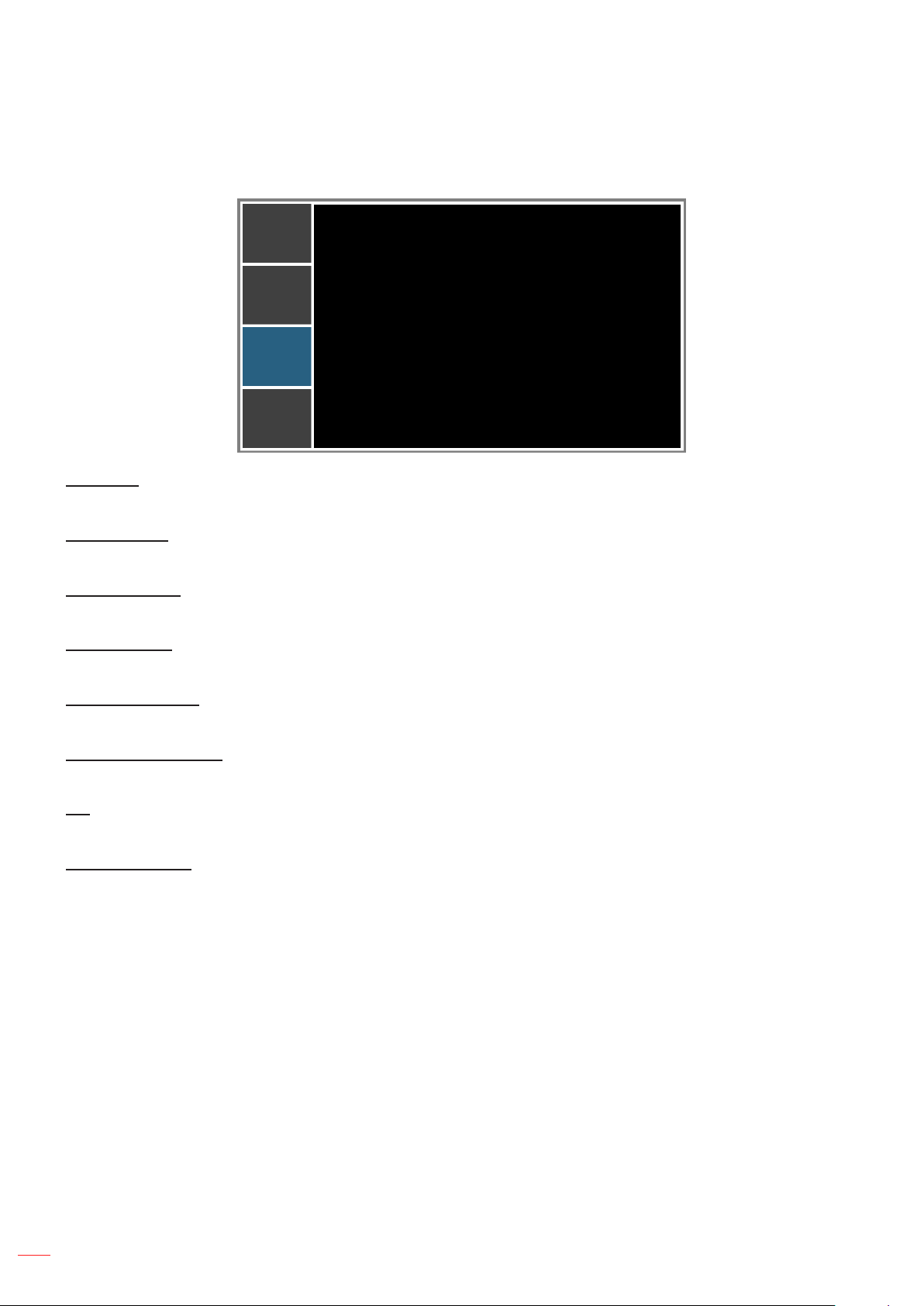
SETUP menu
PICTURE
OUTPUT
SETUP
OPTION
Language
Ceiling Mount
Rear Projection
Lens Function
Menu Preferences
Keypad LED Settings
Pin
Communications
SETUP
Language
Choose the multilingual OSD menu.
Ceiling Mount
Turn the image upside down for ceiling-mounted projection.
Rear Projection
Reverse the image so you can project from behind a translucent screen.
Lens Function
English
Auto
Off
On
Congure the lens function settings. Refer to “Lens Function menu” on page 39.
Menu Preferences
Congure the menu preferences settings. Refer to “Menu Preferences menu” on page 40.
Keypad LED Settings
Turn the backlight of keypad on or off.
Pin
Congure the pin settings. Refer to “Pin menu” on page 40.
Communications
Congure the communications settings. Refer to “Communications menu” on page 41.
38
English
Page 39

USING THE PROJECTOR
Lens Function menu
PICTURE
OUTPUT
SETUP
OPTION
Focus
Zoom
Lens Shift
Lens Calibration
Lens Lock
Focus
Adjust focus function on the projected image.
Zoom
Adjust zoom function on the projected image.
Lens Shift
Shift the projected image.
Lens Calibration
Lens Function
No
Perform calibration and return lens to the center position.
Lens Lock
Select this function to prevent all lens motors from moving.
No: Lens shift can be used by user.
Yes: Lens shift will be locked.
English
39
Page 40
USING THE PROJECTOR
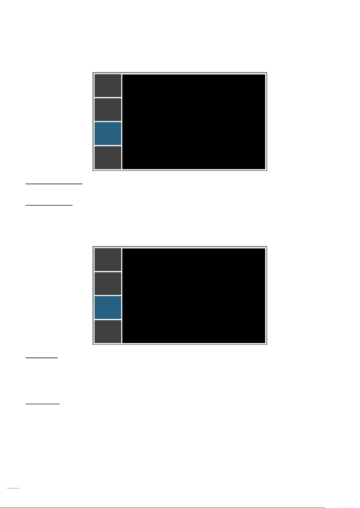
Menu Preferences menu
PICTURE
Menu Transparency
Show Messages
OUTPUT
SETUP
OPTION
Menu Transparency
Change OSD menu background to be transparent.
Show Messages
Display status messages on the screen.
Pin menu
PICTURE
Change PIN
Menu Preferences
0
On
Pin
OffPin Protect
OUTPUT
SETUP
OPTION
Pin Protect
The PIN (personal identication number) feature allows you to password protect your projector. Once you enable
the PIN feature, you must enter the PIN before you can project an image.
Note: The PIN default value is “12345”.
Change PIN
Change the PIN.
40
English
Page 41

USING THE PROJECTOR
Communications menu
PICTURE
OUTPUT
SETUP
OPTION
LAN
WLAN
Network
Serial Port Baud Rate
Serial Port Path
Projector Address
LAN
Congure the local area network (LAN) settings.
DHCP: Turn the DHCP ON/OFF.
IP Address: Select an IP address.
Subnet Mask: Select subnet mask number.
Default Gateway: Select the default gateway of the network connected to the projector.
MAC Address: Display the network MAC Address value.
Apply: Apply Network settings.
WLAN
Communications
19200
RS232
0
Congure the wireless local area network (WLAN) settings.
Enable: Enable/Disable WLAN.
Start IP: Start of IP Address.
End IP: End of IP Address.
Subnet Mask: Assign Network Subnet Mask.
Default Gateway: Assign Network Default Gateway.
MAC Address: Display network MAC Address value.
SSID: Assign Network Service Set Identier.
Network
Congure the general network settings.
Projector Name: Display the projector hostname for Network.
Restart Network: Restart the network.
Network Factory Reset: Perform factory reset on the network settings. The Projector Name, LAN IP,
WLAN IP, and SNMP settings will be reset
Serial Port Baud Rate
Select the serial port and baud rate.
Serial Port Path
Select the serial port path from either RS232 or HDBaseT.
English
41
Page 42
USING THE PROJECTOR
Projector Address
Set the projector address. The projector will respond to IR remotes set either at the same address as the projector
or to IR remotes set to address 0.
How to use web browser to control your projector
1. Turn “On” the DHCP option on projector to allow a DHCP server to automatically assign an IP address.
2. Open the web browser in your PC and type in the projector’s IP address (“SETUP: Communications >
LAN > IP Address”).
Note: The steps in this section is based on Windows 7 operating system.
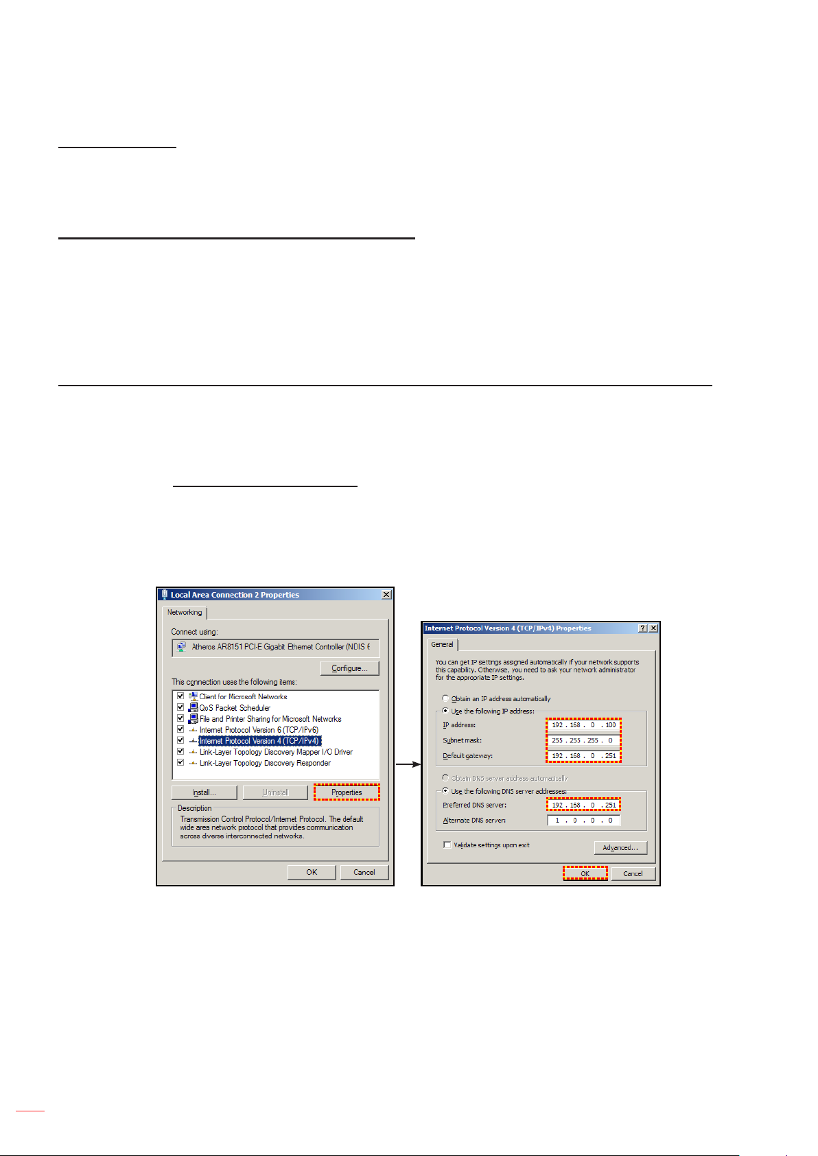
Making a direct connection from your computer to the projector* (For Windows 7 or higher)
1. Turn “Off” the DHCP option on the projector.
2. Congure the IP address, Subnet Mask, and Gateway on projector. Refer to “Communications menu”
on page 41.
3. Open Network and Sharing Center page on your PC, and assign the identical network parameters to
your PC as set on projector. Click “OK” to save the parameters.
Note: The last group (ex: 100) of the IP address should be different from the projector. Make sure the
network parameters (i.e. other groups of the IP address and the Subnet mask) are similar to
those shown in the OSD menu.
42
4. Open the web browser on your computer and type the projector IP address into the URL eld, then
press “Enter”.
English
Page 43
USING THE PROJECTOR
Setup network control settings menu
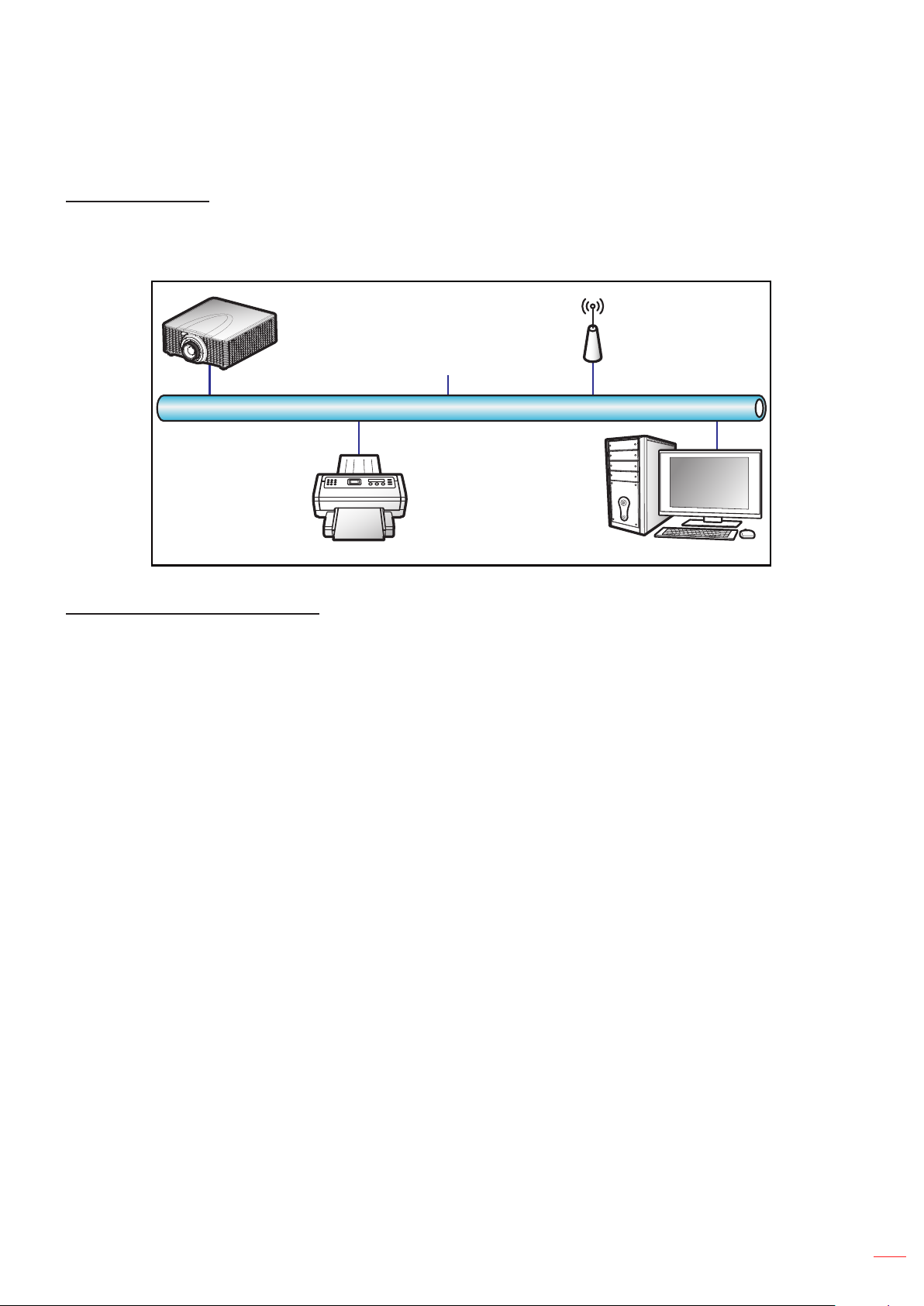
LAN_RJ45 function
For simplicity and ease of operation, the projector provides diverse networking and remote management features.
The LAN / RJ45 function of the projector through a network, such as remotely manage: Power On / Off, Brightness
and Contrast settings. Also you can view the projector status information, such as: Video- Source, etc.
Projector
(Ethernet)
Wired LAN terminal functionalities
This projector can be controlled by using a PC (laptop) or other external device via RJ-45 connector and
compatible ith Crestron / Extron / AMX (Device Discovery) / PJLink.
Crestron is a registered trademark of Crestron Electronics, Inc. of the United States.
Extron is a registered trademark of Extron Electronics, Inc. of the United States.
AMX is a registered trademark of AMX LLC of the United States.
PJLink applied for trademark and logo registration in Japan, the United States of America, and other
countries by JBMIA.
The projector is supported by the specied commands of the Crestron Electronics controller and related software,
for example RoomView
http://www.crestron.com/
This projector is compliant to support Extron device(s) for reference.
http://www.extron.com/
This projector is supported by AMX (Device Discovery).
http://www.amx.com/
This projector supports all commands of PJLink Class1 (Version 1.00).
http://pjlink.jbmia.or.jp/english/
For more detailed information about the various types of external devices which can be connected to the LAN /
RJ45 port and remote control the projector, as well as the supported commands for these external devices, please
contact the Support-Service directly.
®.
English
43
Page 44
USING THE PROJECTOR
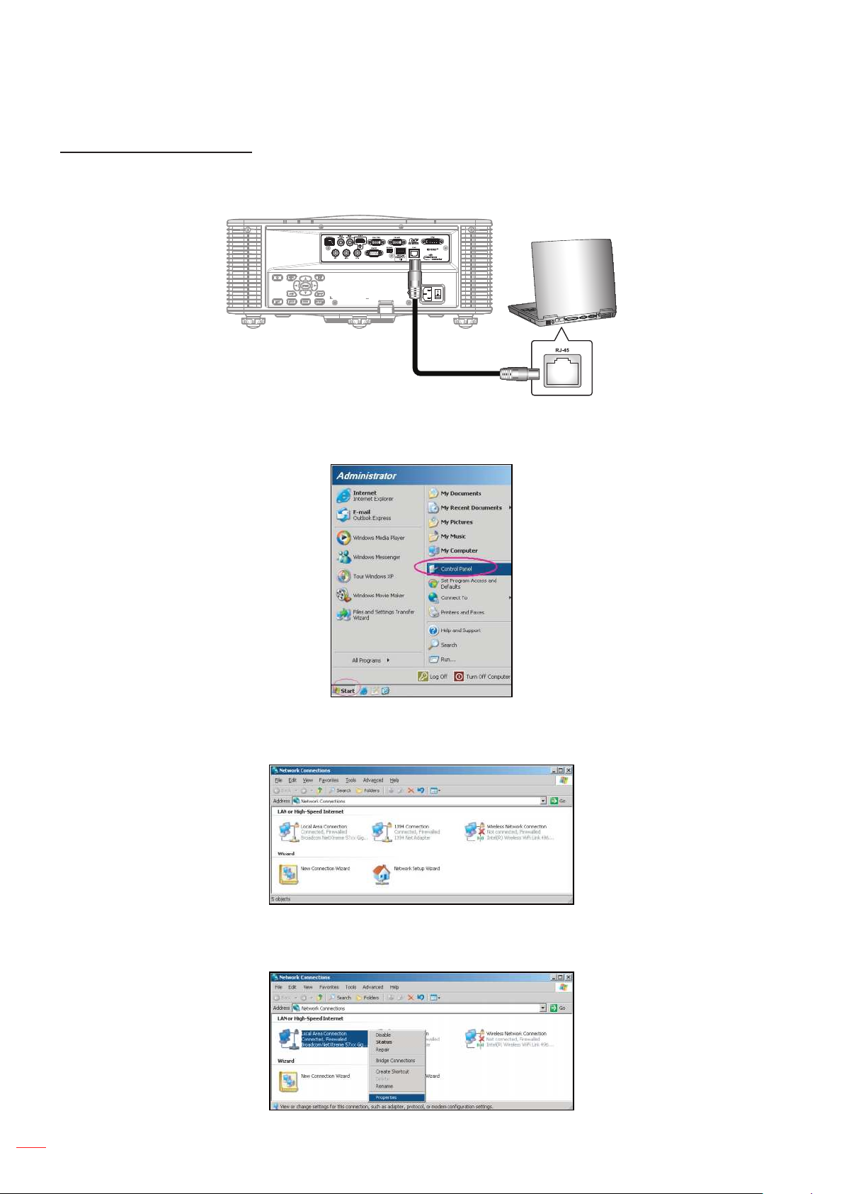
LAN RJ45 (For Windows XP)
1. Connect an RJ45 cable to RJ-45 connector on the projector and the PC (laptop).
2. On the PC (Laptop), select Start > Control Panel > Network Connections.
3. Right-click on the Local Area Connection, and select Property.
4. In the Properties window, select the General tab, and select Internet Protocol (TCP / IP).
44
English
Page 45
USING THE PROJECTOR
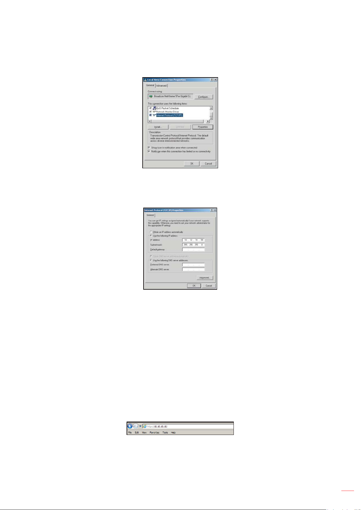
5. Click “Properties”.
6. Type in the IP address and Subnet mask, then press “OK”.
7. Press the “Menu” button on the projector.
8. Select SETUP > Communications > LAN.
9. Enter the following connection parameters:
± DHCP: Off
± IP Address: 10.10.10.10
± Subnet Mask: 255.255.255.0
± Default Gateway: 0.0.0.0
10. Press “Enter” to conrm settings.
11. Open a web browser, for example Microsoft Internet Explorer with Adobe Flash Player 9.0 or higher
installed.
12. In the Address bar, input the projector’s IP address: 10.10.10.10.
English
45
Page 46
USING THE PROJECTOR
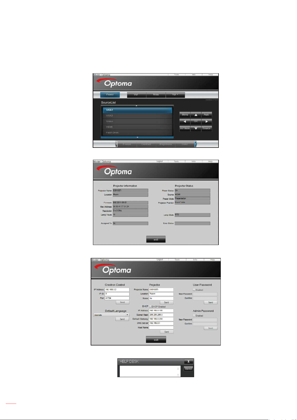
13. Press “Enter”.
The projector is setup for remote management. The LAN / RJ45 function displays as follows:
Information page
Main page
Tool page
Contact IT helpdesk
46
English
Page 47
USING THE PROJECTOR
RS232 by Telnet Function
There is alternative RS232 command control way, in projector so called “RS232 by TELNET” for LAN / RJ45
interface.
Quick Start-Guide for “RS232 by Telnet”
Check and get the IP address on OSD of the projector.
Make sure that the PC / laptop can access the web-page of the projector.
Make sure that “Windows Firewall” setting is set disabled in case of “TELNET” function ltering out by
PC / laptop.
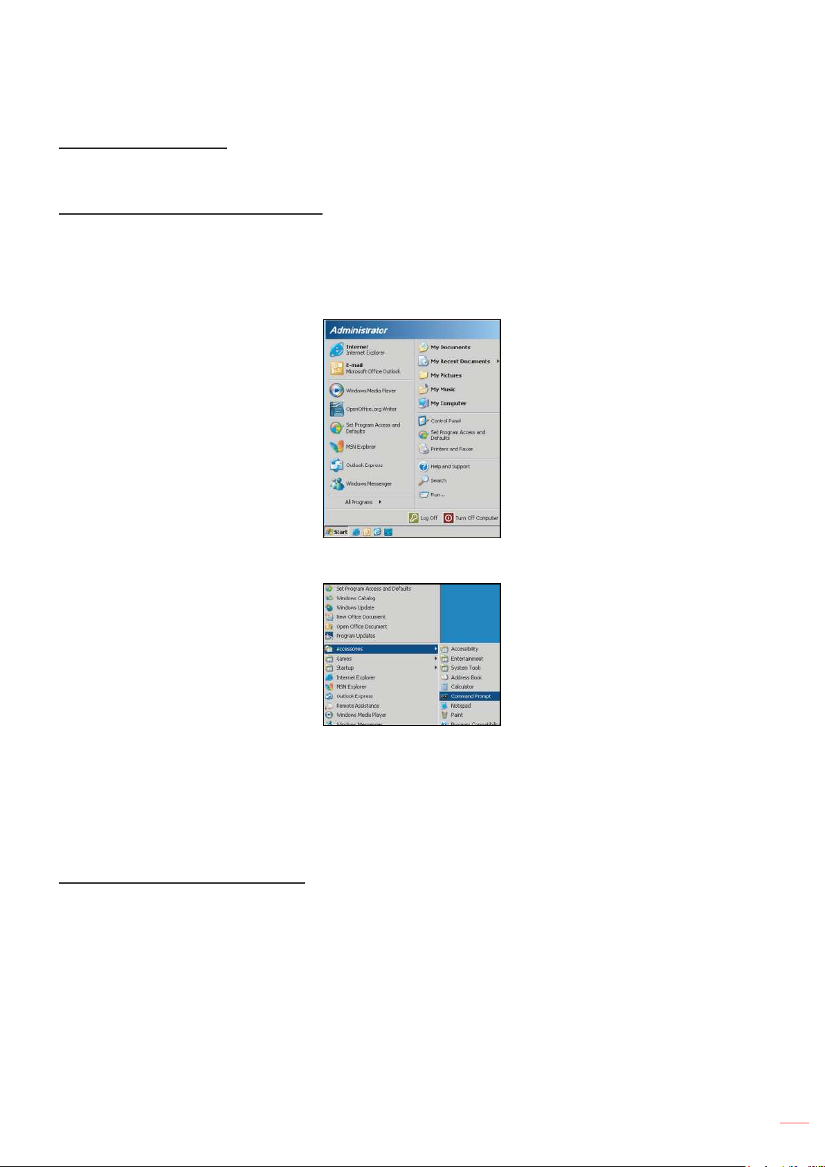
1. Select Start > All Programs.> Accessories > Command Prompt.
2. Input the command format as follows:
± telnet ttt.xxx.yyy.zzz 3023 (“Enter” key pressed)
± (ttt.xxx.yyy.zzz: IP-Address of the projector)
3. If Telnet-Connection ready, and user can have RS232 command input, then “Enter” key pressed, the
RS232 command will be workable.
Specication for “RS232 by TELNET”:
1. Telnet: TCP.
2. Telnet port: 3023 (for more detail, kindly please get contact with the service agent or team).
3. Telnet utility: Windows “TELNET.exe” (console mode).
4. Disconnection for RS232-by-Telnet control normally: Close
5. Windows Telnet utility directly after TELNET connection ready.
± Limitation 1 for Telnet-Control: there is less than 50 bytes for successive network payload for
Telnet-Control application.
± Limitation 2 for Telnet-Control: there is less than 26 bytes for one complete RS232 command for
Telnet-Control.
± Limitation 3 for Telnet-Control: Minimum delay for next RS232 command must be more than 200 (ms).
English
47
Page 48
USING THE PROJECTOR
OPTION menu
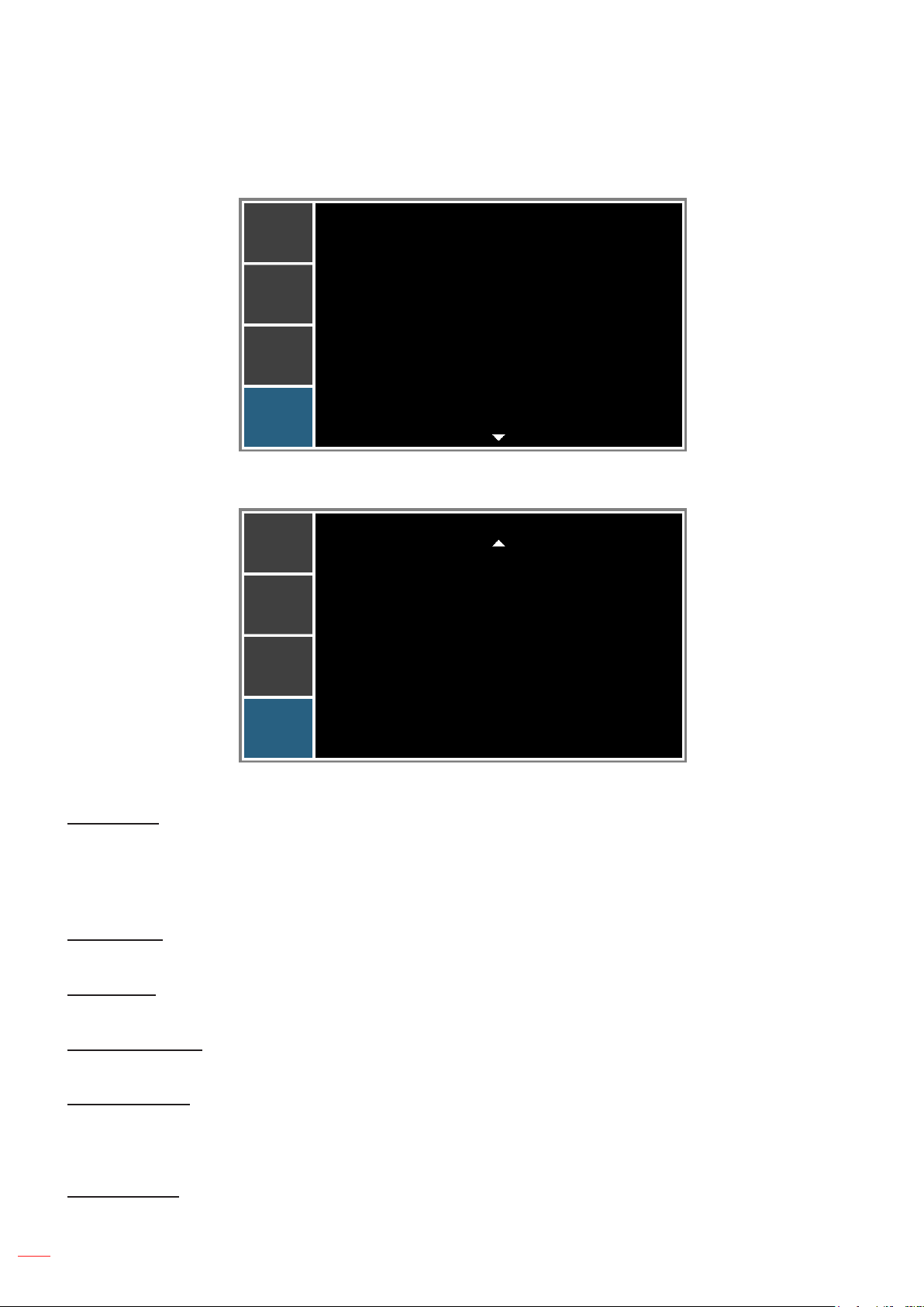
PICTURE
OUTPUT
SETUP
OPTION
PICTURE
OUTPUT
SETUP
Auto Source
High Altitude
Test Pattern
Background Color
Hot-Key settings
Power Settings
Light Source Settings
Light Sensor
Information
Factory Reset
Service
OPTION
On
Off
Off
Logo
Blank Screen
OPTION (1/2)
OPTION
OPTION
OPTION (2/2)
Auto Source
Use this option to enable/disable input sources.
On: The projector will search for other signals if the current input signal is lost.
Off: The projector will only search current input connection.
High Altitude
When “On” is selected, the fans will spin faster. This feature is useful in high altitude areas where the air is thin.
Test Pattern
Display a test pattern or select “Off” to turn off a test pattern.
Background Color
Use this feature to display a “Logo”, “Blue”, “Black”, or “White” screen when no signal is available.
Hot-Key settings
Assign a different function to the hot-key on the remote control by highlighting the function in the list and pressing
“Enter”. Choose a function that does not already have a dedicated button, and assign the hot-key to that function,
allowing you to quickly and easily use the chosen function.
Power Settings
Congure the power settings. Refer to “Power Settings menu” on page 50.
English
48
Page 49

USING THE PROJECTOR
Light Source Settings
Congure the light source settings. Refer to “Light Source Settings menu” on page 51.
Light Sensor
Light Sensor Calibration: Calibrate the Light Sensor for use with the Constant Luminance mode,
which allows the projector to be set for constant brightness. If the Light Sensor has not been
calibrated, Constant Luminance mode will be disabled.
Calibrated:
- Yes: Light Sensor has been calibrated.
- No: Light Sensor has not been calibrated.
Information
Display the projector information for source, resolution, and software version on the screen.
Factory Reset
Restore all settings to their default value. It will not reset network.
Service
Service only.
English
49
Page 50
USING THE PROJECTOR
Power Settings menu
PICTURE
OUTPUT
SETUP
OPTION
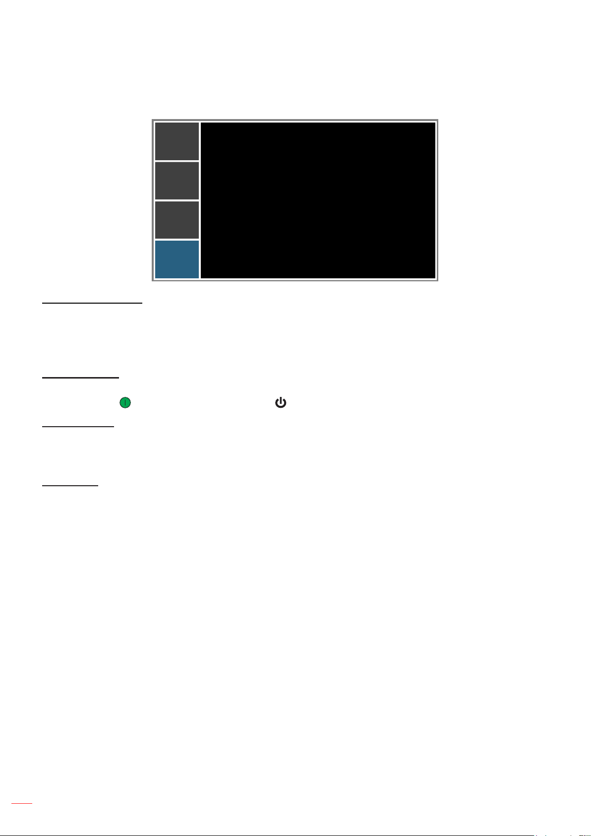
Standby Power Mode
Direct Power On
Auto Power Off
Sleep Timer
Power Settings
Communication mode
Off
20 Mins
No
Standby Power Mode
Set the standby power mode setting.
0.5W mode: The projector is in standby mode when connected to AC power. (<0.5W)
Communication mode: The projector could be controlled via the LAN terminal during power standby.
Direct Power On
Choose “On” to activate Direct Power mode. The projector will automatically power on when AC power is supplied,
without pressing “
” on the remote control or press “ ” on the projector keypad.
Auto Power Off
Set the countdown timer interval. The countdown timer will start, when there is no signal being sent to the projector.
The projector will automatically power off when the countdown has nished (in minutes). The default setting is 20
minutes.
Sleep Timer
Sets the countdown timer interval. The countdown timer will start, with or without a signal being sent to the
projector. The projector will automatically power off when the countdown has nished.
Note: The value of sleep timer will be reset to zero after the projector is powered off.
50
English
Page 51

USING THE PROJECTOR
Light Source Settings menu
PICTURE
OUTPUT
SETUP
OPTION
Light Source Mode
Constant Power Settings
Constant Luminance Settings
Total Projector Hours
Light Source Settings
Constant Power
0
0
11
Light Source Mode
Set the light source mode setting. When “Eco Mode” is selected, the projector will adjust to the lowest fan speed
and switch the laser diode power to the minimum setting.
Constant Power Settings
Set the value of the laser diode power (in Watts).
Constant Luminance Settings
Set the value for the Constant Luminance Settings to maintain constant brightness. The light sensor will monitor
the light level and will apply more power as the laser brightness decays naturally over time. When the laser setting
reaches maximum power, it will remain at this setting.
Note: The light sensor needs to be calibrated for Constant Luminance mode to work properly.
Total Projector Hours
Display the projection time.
English
51
Page 52
ADDITIONAL INFORMATION
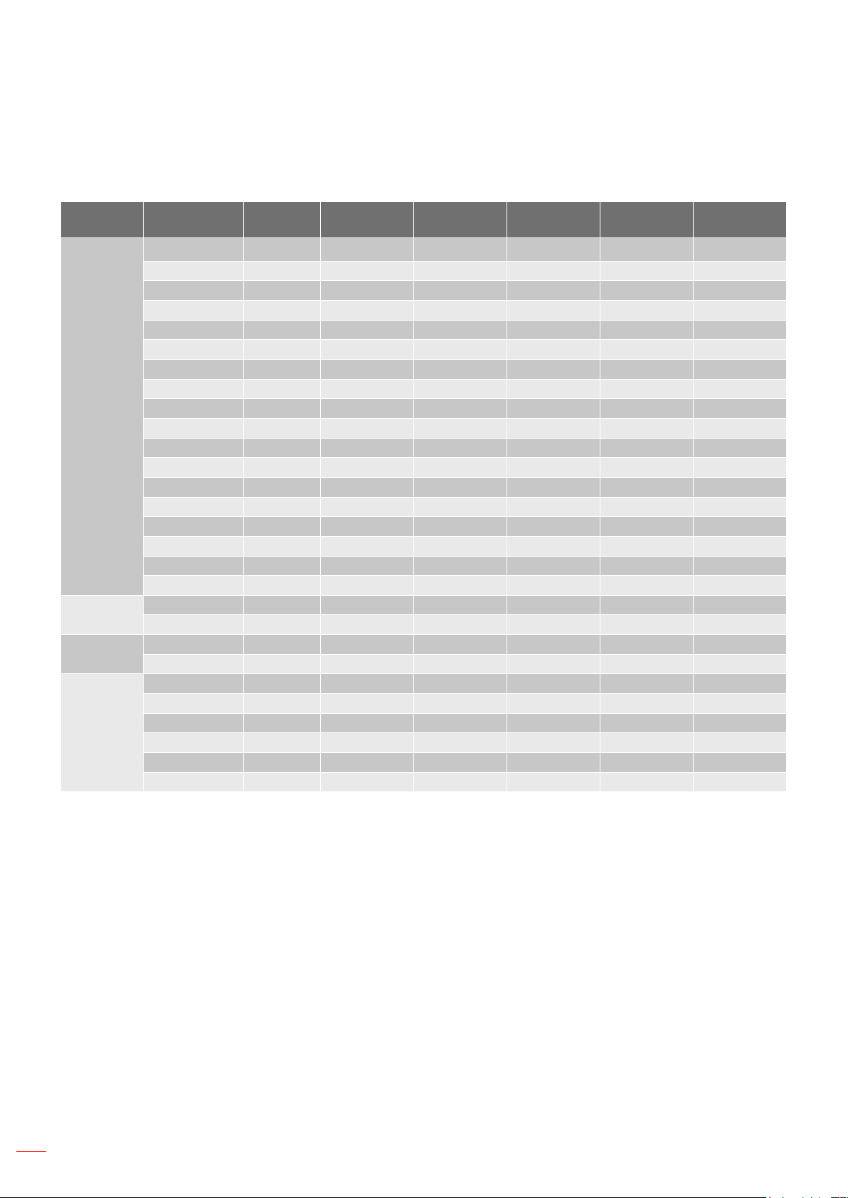
Compatible resolutions
Timing Table
Signal Type Resolution
800x600 60 V V V V —
800x600 72 V V V V —
800x600 75 V V V V —
832x624 75 V V V V —
1024x768 60 V V V V —
1024x768 75 V V V V —
1152x870 75 V V V V —
1280x800 75 V V V V —
PC
SDTV
EDTV
HDTV
1280x1024 60 V V V V —
1280x1024 75 V V V V —
1400x1050 60 V V V V —
1440x900 60 V V V V —
1440x900 75 V V V — —
1600x1200 60 V V V V —
1680x1050 60 V V V V —
1920X1080 50 V V V — —
1920X1080 60 V V V V —
1920X1200RB 60 V V V V —
480i 60 V V V V V
576i 50 V V V V V
480p 60 V V V V V
576p 50 V V V V V
1080i 30 V V V V V
720p 50 V V V V V
720p 60 V V V V V
1080p 24 V V V V V
1080p 50 V V V V V
1080p 60 V V V V V
Frame rate
(Hz)
HDMI
HDBaseT
DVI VGA Component
Note: “RB” means “reduced blanking”.
English
52
Page 53

ADDITIONAL INFORMATION
EDID Table
OPTOMA WUXGA EDID Table
Digital
Established Timing: Standard Timing: Detail Timing:
720 x 400 @ 70 Hz 1440 x 900 @ 75Hz 1920 x 1200 @ 60Hz
720 x 400 @ 88 Hz 1280 x 800 @ 75Hz 1920 X 1080 @ 60Hz
640 x 480 @ 60 Hz 1280 x 1024 @ 60Hz 1280 x720P @ 60Hz
640 x 480 @ 67 Hz 1360 x 765 @ 60Hz 1920 x 1080i @ 60Hz
640 x 480 @ 72 Hz 1440 x 900 @ 60Hz 1920 x 1080i @ 50Hz
640 x 480 @ 75 Hz 1400 x 1050 @ 60Hz 720 x 480p @ 60Hz
800 x 600 @ 56 Hz 1600 x 1200@ 60Hz 720 x 576p @ 50Hz
800 x 600 @ 60 Hz 1680 x 1050@ 60Hz
800 x 600 @ 72 Hz
800 x 600 @ 75 Hz
832 x 624 @ 75 Hz
1024 x 768 @ 60 Hz
1024 x 768 @ 70 Hz
1024 x 768 @ 75 Hz
1280 x 1024 @ 75 Hz
1152 x 870 @ 75 Hz
Analog
Established Timing: Standard Timing: Detail Timing:
720 x 400 @ 70 Hz 1440 x 900 @ 75Hz 1920 x 1200 @ 60Hz
720 x 400 @ 88 Hz 1280 x 800 @ 75Hz 1920 X 1080 @ 60Hz
640 x 480 @ 60 Hz 1280 x 1024 @ 60Hz
640 x 480 @ 67 Hz 1360 x 765 @ 60Hz
640 x 480 @ 72 Hz 1440 x 900 @ 60Hz
640 x 480 @ 75 Hz 1400 x 1050 @ 60Hz
800 x 600 @ 56 Hz 1600 x 1200@ 60Hz
800 x 600 @ 60 Hz 1680 x 1050@ 60Hz
800 x 600 @ 72 Hz
800 x 600 @ 75 Hz
832 x 624 @ 75 Hz
1024 x 768 @ 60 Hz
1024 x 768 @ 70 Hz
1024 x 768 @ 75 Hz
1280 x 1024 @ 75 Hz
1152 x 870 @ 75 Hz
English
53
Page 54
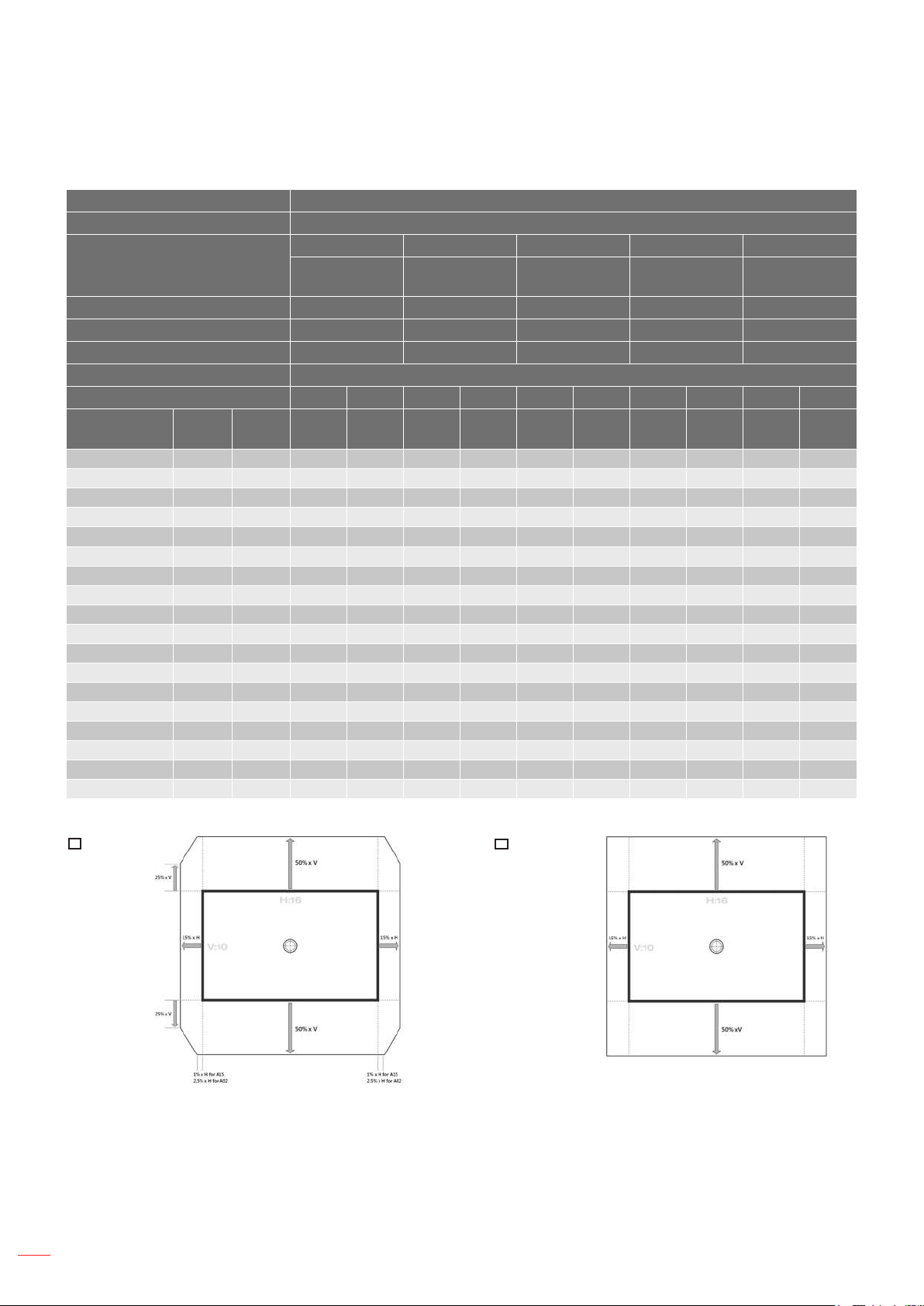
ADDITIONAL INFORMATION
Image size and projection distance
Platform WUXGA (16:10)
DMD 0.67”
A01 A02 A03 A13 A15
Projection Lens
Wide Zoom Standard Long Zoom
Throw Ratio 0.95-1.22 1.22-1.53 1.53-2.92 2.90-5.50 0.75-0.95
Zoom Ratio 1.28X 1.25X 1.9X 1.9X 1.26X
Throw Distance 1.03~7.88m 1.32~9.88m 1.65~18.86m 3.13~35.53m 0.81-6.14m
Projection screen size Projection distance (m)
Throw Ratio 0.95 1.22 1.22 1.53 1.53 2.92 2.9 5.5 0.75 0.95
Diagonal
(inch)
50 0.67 1.08 1.03 1.32 1.32 1.65 1.65 3.15 3.13 5.94 0.81 1.03
60 0.81 1.29 1.23 1.57 1.57 1.97 1.97 3.77 3.74 7.10 0.97 1.23
70 0.94 1.51 1.43 1.84 1.84 2.31 2.31 4.41 4.38 8.31 1.13 1.43
80 1.08 1.72 1.63 2.10 2.10 2.63 2.63 5.02 4.99 9.46 1.29 1.63
90 1.21 1.94 1.84 2.37 2.37 2.97 2.97 5.66 5.63 10.67 1.46 1.84
100 1.35 2.15 2.04 2.62 2.62 3.29 3.29 6.28 6.24 11.83 1.61 2.04
110 1.48 2.37 2.25 2.89 2.89 3.63 3.63 6.92 6.87 13.04 1.78 2.25
120 1.62 2.58 2.45 3.15 3.15 3.95 3.95 7.53 7.48 14.19 1.94 2.45
130 1.75 2.8 2.66 3.42 3.42 4.28 4.28 8.18 8.12 15.40 2.10 2.66
140 1.88 3.02 2.87 3.68 3.68 4.62 4.62 8.82 8.76 16.61 2.27 2.87
150 2.02 3.23 3.07 3.94 3.94 4.94 4.94 9.43 9.37 17.77 2.42 3.07
160 2.15 3.45 3.28 4.21 4.21 5.28 5.28 10.07 10.01 18.98 2.59 3.28
170 2.29 3.66 3.48 4.47 4.47 5.60 5.60 10.69 10.61 20.13 2.75 3.48
180 2.42 3.88 3.69 4.73 4.73 5.94 5.94 11.33 11.25 21.34 2.91 3.69
190 2.56 4.09 3.89 4.99 4.99 6.26 6.26 11.94 11.86 22.50 3.07 3.89
200 2.69 4.31 4.09 5.26 5.26 6.59 6.59 12.59 12.50 23.71 3.23 4.09
250 3.37 5.38 5.11 6.56 6.56 8.23 8.23 15.71 15.60 29.59 4.04 5.11
300 4.04 6.46 6.14 7.88 7.88 9.88 9.88 18.86 18.73 35.53 4.85 6.14
Height
(m)
Width
(m)
Min
(m)
Max
(m)
Min
(m)
Max
(m)
Min
(m)
Max
(m)
Ultra-Long
Zoom
Min
Max
(m)
(m)
Short Throw
Min
Max
(m)
(m)
54
V projected
H projected
A02/A15
English
projected
image
image height
image width
projected
image
V projected
image height
H projected
image width
A01/A03/A13
Page 55
ADDITIONAL INFORMATION
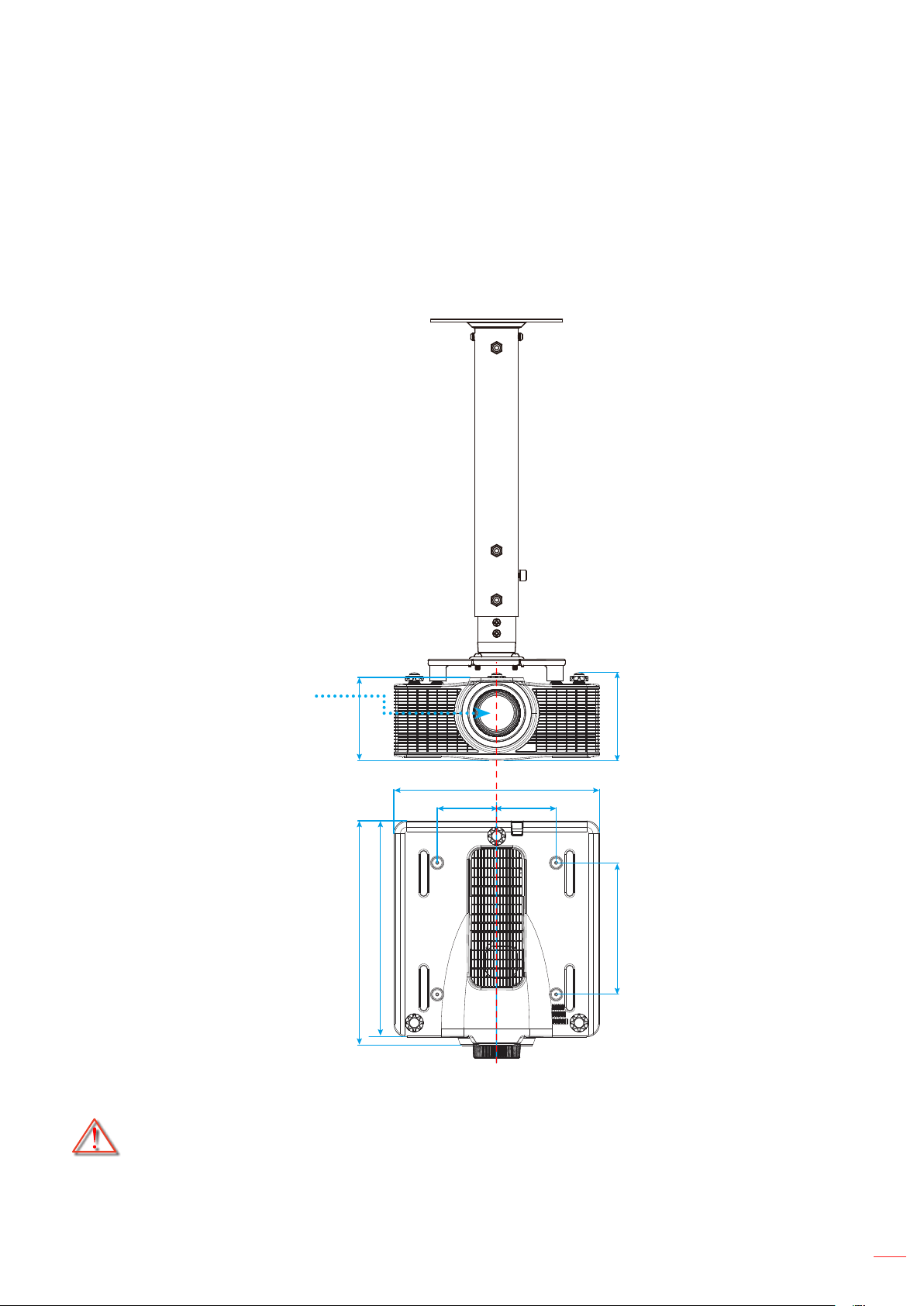
Projector dimensions and ceiling mount installation
1. To prevent damage to your projector, please use the Optoma ceiling mount.
2. If you wish to use a third party ceiling mount kit, please ensure the screws used to attach a mount to
the projector meet the following specications:
Screw type: M6 x 4
Minimum screw length: 20mm
Lens
195.0
529.0
509.0
140.0
484.0
140.0
206.3
310.0
Unit: mm
Note: Please note that damage resulting from incorrect installation will void the warranty.
Warning:
If you buy a ceiling mount from another company, please be sure to use the correct screw size.
Screw size will vary depending on the thickness of the mounting plate.
Be sure to keep at least 30mm (3cm) gap between the ceiling and the bottom of the projector.
Avoid installing the projector near a heat source.
English
55
Page 56
ADDITIONAL INFORMATION
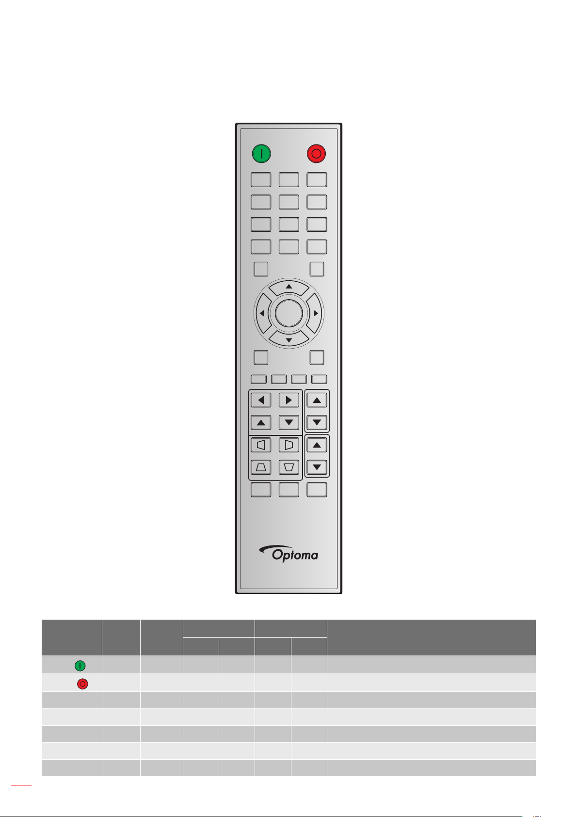
IR remote codes
ON OFF
21 3
54 6
87 9
Info
Auto
Enter
Menu Exit
Gamma Bright Cont. PIP
Lens H
Lens V
Keystone H
Keystone V
Shutter
(AV Mute)
0
Hot Key
Mode
Input
Focus
Zoom
Pattern
56
English
Key Legend
ON (
OFF (
)
)
Key
Position
Repeat
Format
1 F1 32 CD 02 FD Press to turn on the projector.
2 F1 32 CD 2E D1 Press to turn off the projector.
Address Data
Description
Byte 1 Byte 2 Byte 3 Byte 4
1 3 F1 32 CD 72 8D Use as numeric keypad number “1”.
2 4 F1 32 CD 73 8C Use as numeric keypad number “2”.
3 5 F1 32 CD 74 8B Use as numeric keypad number “3”.
4 6 F1 32 CD 75 8A Use as numeric keypad number “4”.
5 7 F1 32 CD 77 88 Use as numeric keypad number “5”.
Page 57
ADDITIONAL INFORMATION
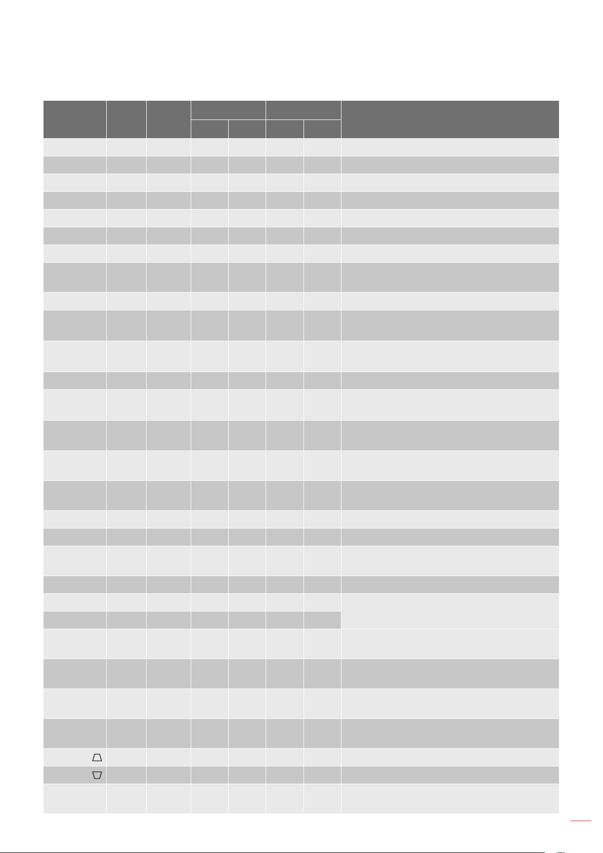
Key Legend
6 8 F1 32 CD 78 87 Use as numeric keypad number “6”.
7 9 F1 32 CD 79 86 Use as numeric keypad number “7”.
8 10 F1 32 CD 80 7F Use as numeric keypad number “8”.
9 11 F1 32 CD 81 7E Use as numeric keypad number “9”.
Info 12 F1 32 CD 82 7D Press to display source image information.
0 13 F1 32 CD 25 DA Use as numeric keypad number “0”.
Mode 14 F1 32 CD 05 FA Press to select the preset display mode.
Auto 15 F1 32 CD 04 FB
Input 16 F1 32 CD 18 E7 Press to select an input signal.
UP (▲) 17 F1 32 CD 0F F0
LEFT (◄) 18 F1 32 CD 11 EE
Enter 19 F1 32 CD 14 EB Press to conrm your item selection.
RIGHT (►) 20 F1 32 CD 10 EF
Key
Position
Repeat
Format
Address Data
Description
Byte 1 Byte 2 Byte 3 Byte 4
Press to automatically synchronize the
projector to the input source.
Press to select items or make adjustments to
our selection.
Press to select items or make adjustments to
our selection.
Press to select items or make adjustments to
our selection.
DOWN (▼) 21 F1 32 CD 12 ED
Menu 22 F1 32 CD 0E F1
Exit 23 F1 32 CD 2A D5
Gamma 24 F1 32 CD 2B D4 Press to adjust mid-range levels..
Bright 25 F1 32 CD 28 D7 Press to adjust amount of light in the image.
Cont. 26 F1 32 CD 29 D6
PIP 27 F1 32 CD 43 BC Press to turn on/off the PIP/PBP function.
Lens H◄ 28 F1 32 CD 41 BE
Lens H ► 29 F1 32 CD 42 BD
Focus ▲ 30 F1 32 CD 86 79
Lens V ▲ 31 F1 32 CD 34 CB
Lens V ▼ 32 F1 32 CD 32 CD
Press to select items or make adjustments to
our selection.
Press to display the on-screen display menus
for projector.
Press to return to previous level or exit menus
if at top level.
Press to adjust difference between dark and
light.
Press to adjust the position of the image
horizontally.
Press to adjust focus to improve image clarity
as desired.
Press to adjust the position of the image
vertically.
Press to adjust the position of the image
vertically.
Focus ▼ 33 F1 32 CD 26 D9
Keystone
Keystone
Zoom ▲ 36 F1 32 CD 52 AD
34 F1 32 CD 87 78 Press to adjust the vertical keystone.
35 F1 32 CD 51 AE Press to adjust the vertical keystone.
Press to adjust focus to improve image clarity
as desired.
Press to adjust zoom to achieve a desired
image size.
English
57
Page 58
ADDITIONAL INFORMATION
Key Legend
Keystone
Keystone
Zoom ▼ 39 F1 32 CD 55 AA
Shutter
(AV Mute)
Hot Key 41 F1 32 CD 57 A8 Press to select your preset keys quickly.
Pattern 42 F1 32 CD 58 A7 Press to display a test pattern.
Key
Position
37 F1 32 CD 53 AC Press to adjust the horizontal keystone.
38 F1 32 CD 54 AB Press to adjust the horizontal keystone.
40 F1 32 CD 56 A9 Press to hide/unhide the screen picture.
Repeat
Format
Address Data
Description
Byte 1 Byte 2 Byte 3 Byte 4
Press to adjust zoom to achieve a desired
image size.
58
English
Page 59

ADDITIONAL INFORMATION
Troubleshooting
If you experience a problem with your projector, please refer to the following information. If a problem persists,
please contact your local reseller or service center.
Image problems
No image appears on-screen
Ensure all the cables and power connections are correctly and securely connected as described in the
"Installation" section.
Ensure the pins of connectors are not crooked or broken.
Ensure that the "Shutter (AV Mute)" feature is not turned on.
Image is out of focus
Press the Focus ▲ or Focus ▼ button on the remote control to adjust the focus until the image is
sharp and legible.
Make sure the projection screen is between the required distance from the projector. (Please refer to
page 54).
The image is stretched when displaying 16:10 DVD title
When you play anamorphic DVD or 16:10 DVD, the projector will show the best image in 16:10 format
on projector side.
If you play 4:3 format DVD title, please change the format as 4:3 in projector OSD.
Please setup the display format as 16:10 (wide) aspect ratio type on your DVD player.
Image is too small or too large
Press the Zoom ▲ or Zoom ▼ button on the remote control to increase or decrease the projected
image size.
Move the projector closer to or further from the screen.
Press "Menu" on the projector panel, go to "OUTPUT-->Aspect Ratio". Try the different settings.
Image has slanted sides:
If possible, reposition the projector so that it is centered on the screen and below the bottom of the
screen.
Use "OUTPUT-->Image Warping-->V Keystone" from the OSD to make an adjustment.
Image is reversed
Select “SETUP-->Rear Projection-->On” from the OSD to reverse the image so you can project from
behind a translucent screen.
English
59
Page 60

ADDITIONAL INFORMATION
Other problems
The projector stops responding to all controls
If possible, turn off the projector, then unplug the power cord and wait at least 20 seconds before
reconnecting power.
Remote control problems
If the remote control does not work
Check the operating angle of the remote control is pointed within ±30° (horizontally or vertically) to the
IR receivers on the projector.
Make sure there are not any obstructions between the remote control and the projector. Move to within
10 m (32.8 ft) of the projector.
Make sure batteries are inserted correctly.
Replace batteries if they are exhausted.
60
English
Page 61

ADDITIONAL INFORMATION
Warning indicators
LED status indicators
The LED status indicators are located on the rear of the projector. Each LED is dened below.
LED Type LED Status Projector State
Off Laser diode is off
Light LED
Status LED
AV Mute
Solid Orange Laser diode time has expired
Solid Green Laser diode is on and operating correctly
Flashing Red When projector has lost over 60% initial luminance
Off AC power is off (without AC plug in)
AC has been applied, projector is in standby mode
Off
Solid Green Projector is powered up and operating normally
Flashing Green Projector communications
Flashing Orange Projector is in cool down mode or startup mode
Flashing (alternating)
Green/Orange
Solid Red Over temperature and projector will automatically shut down
Flashing Red Fan failure and projector will automatically shut down
Solid Green Light is on - image is displayed
Solid Orange Light is on - image is blank
Note: Status LED cannot be ashing red, as this is reserved for
an error condition. Status LED is off but keypad LED will indicate
Standby Mode.
Projector is in ash update state
Power off:
Powering Off...
Press OFF key to Conrm
Light power impact due to high ambient temperature:
The light power will be reduced
due to the high ambient temperature.
DMD life time impact due to high ambient temperature:
Running the projector at high ambient temperature
will impact DMD life time.
English
61
Page 62

ADDITIONAL INFORMATION
LAN Control Setting:
LAN Control Port
AMX 9131
Crestron 41794
PJ-Link 4352
Telnet 23
Http 80
62
English
Page 63

ADDITIONAL INFORMATION
Specications
Optical Description
Resolution WUXGA (1920x1200)
Lens Power Zoom/Focus
Laser Diode
Image size (diagonal) 50~300”
Projection distance Please refer to “Image size and projection distance” table on page 54
Electrical Description
Inputs
Outputs 1 x VGA Out (Support VGA loops through to monitor) (Monitor Out)
Control port
400W Laser Diode @ Normal operation
240W Laser Diode @ ECO operation
1 x HDMI (version1.4) (with locking screw)
1 x DVI-D (only support digital signal)
1 x VGA (D-Sub 15pin) (Computer In)
1 x HDBaseT
1 x Component(Y/Pb/Pr)
1 x RS232 (D-sub 9 pin) (PC Control)
1 x Wired in (3.5mm phone jack) (Remote In)
1 x Wired out (3.5mm phone jack) (Remote Out)
1 x USB type A (for WiFi dongle purpose)
1 x Mini USB (for LAN FW upgrade only) (Service)
1 x RJ45 (LAN)
Power requirement AC 100V - 240V, 50/60Hz
Input current 6.5A - 2.5A
Mechanical Description
Installation orientation Table Top, Ceiling Mount, Portrait
Dimensions 484 (W) x 509 (D) x 185 (H) mm (without lens, w/o elevators)
Weight 18.5 kg
Environmental conditions
Note: All specications are subject to change without notice.
Operating: 5~40°C (>35°C, auto dim to 75% normal mode),
10~85%RH, non-condensing
English
63
Page 64
ADDITIONAL INFORMATION
Optoma global ofces
For service or support, please contact your local ofce.
USA
3178 Laurelview Ct. 888-289-6786
Fremont, CA 94538, USA 510-897-8601
www.optomausa.com [email protected]
Canada
3178 Laurelview Ct. 888-289-6786
Fremont, CA 94538, USA
www.optomausa.com
510-897-8601
[email protected]
Latin America
3178 Laurelview Ct. 888-289-6786
Fremont, CA 94538, USA 510-897-8601
www.optomausa.com
Europe
42 Caxton Way, The Watford Business Park
Watford, Hertfordshire,
WD18 8QZ, UK +44 (0) 1923 691 800
www.optoma.eu +44 (0) 1923 691 888
Service Tel : +44 (0)1923 691865 [email protected]
Benelux BV
Randstad 22-123 +31 (0) 36 820 0252
1316 BW Almere +31 (0) 36 548 9052
The Netherlands
www.optoma.nl
Japan
Taiwan
12F., No.213, Sec. 3, Beixin Rd., +886-2-8911-8600
Xindian Dist., New Taipei City 231,
Taiwan, R.O.C. [email protected]
www.optoma.com.tw asia.optoma.com
+886-2-8911-6550
Hong Kong
Unit A, 27/F Dragon Centre,
79 Wing Hong Street,
Cheung Sha Wan, +852-2370-1222
Kowloon, Hong Kong www.optoma.com.hk
+852-2396-8968
China
5F, No. 1205, Kaixuan Rd., +86-21-62947376
Changning District
Shanghai, 200052, China www.optoma.com.cn
+86-21-62947375
France
Bâtiment E +33 1 41 46 12 20
81-83 avenue Edouard Vaillant +33 1 41 46 94 35
92100 Boulogne Billancourt, France [email protected]
Spain
C/ José Hierro,36 Of. 1C +34 91 499 06 06
28522 Rivas VaciaMadrid, +34 91 670 08 32
Spain
Deutschland
Wiesenstrasse 21 W +49 (0) 211 506 6670
D40549 Düsseldorf, +49 (0) 211 506 66799
Germany [email protected]
Scandinavia
PO.BOX 9515
3038 Drammen
Norway
Korea
WOOMI TECH.CO.,LTD. +82+2+34430004
4F, Minu Bldg.33-14, Kangnam-Ku, +82+2+34430005
Seoul,135-815, KOREA
korea.optoma.com
64
English
Page 65

www.optoma.com
 Loading...