

Page 1
Installation Guide
HDBV3100, HDBV3090, HDBV3080
Page 2

Installation Guide
HDBV3100, HDBV3090, HDBV3080
BigVizion In-Wall Rear Projection Display
Optoma’s BigVizion is an in-wall modular rear projection display consisting of a framing system, system control
components, a mirror, screen frame assembly and DLP® light engine.
The BigVizion is a modular designed system and offers front access to all components through a movable front
screen frame assembly.
HDBV3100, HDBV3090, HDBV3080
The BigVizion is available in three models: HDBV3100 (100"), HDBV3090 (90") and HDBV3080 (80"). These models differ
only by size. The installation details with front and side views are included in the master frame installation section of this
guide.
For more information, please visit our website at:
http://www.optomausa.com/BigVizion
Installation Guide 2
Page 3

About this Manual
This manual exclusively describes the set-up and use of Optoma’s in-wall rear projection displays.
This manual covers the installation steps in the following order:
• Creating wall openings for BigVizion 100", 90", 80"
• Unpacking and identifying all system parts and components
• Preparing the BigVizion for installation
• Installing the BigVizion frame components
• Configuring all system components
• Adjustment, alignment, and operation
• Servicing
Installation Guide
HDBV3100, HDBV3090, HDBV3080
For more information, please visit our website at:
http://www.optomausa.com/BigVizion
Installation Guide 3
Page 4

Installation Guide
HDBV3100, HDBV3090, HDBV3080
FCC WARNING
This equipment has been tested and found to comply with the limits for a “Class B” digital device, pursuant to Part
15 of the FCC rules. These limits are designed to provide reasonable protection against harmful interference in a
residential installation. This equipment generates, uses, and can radiate radio frequency energy, and if not installed
and used in accordance with the instructions, may cause harmful interference to radio communications. However,
there is no guarantee that interference will not occur in a particular installation. If this equipment does cause harmful
interference to radio or television reception (this can be determined by turning the equipment off and on), the user is
encouraged to try to correct the interference by one or more of the following measures:
• Reorient or relocate the receiving antenna
• Increase the separation between the equipment and the receiver
• Connect the equipment to an outlet on a circuit that the receiver is not connected to
• Consult the dealer or an experienced radio/TV technician for help
Any changes or modifications to this “Class B” digital device that has not been expressly approved by Optoma
Technology, Inc. will void the user’s authority to operate the equipment.
TRADEMARK NOTICE
The BigVizionTM is a trademark of Optoma Technology, Inc. All other trademarks and registered trademarks are the
property of their respective owners.
COPYRIGHT NOTICE
© Copyright 2006 Optoma Technology, Inc.
This document contains proprietary information protected by copyright. All rights are reserved. No part of this
manual may be reproduced by any mechanical, electronic, or other means, in any form, without prior written
permission of the manufacturer.
For more information, please visit our website at:
http://www.optomausa.com/BigVizion
Installation Guide 4
Page 5
Installation Guide
HDBV3100, HDBV3090, HDBV3080
Installation Preparation
WARNING:
All installations must be performed in accordance with standard utility practice; The National Electric Code, The
National Electric Safety Code, The Local Electric Code, and any local city ordinances that may apply to building
construction and/or modification to residential structures.
In the event of a conflict regarding any standards governing the installation/construction of the BigVizion system, or
any component thereof, the strongest standard shall apply.
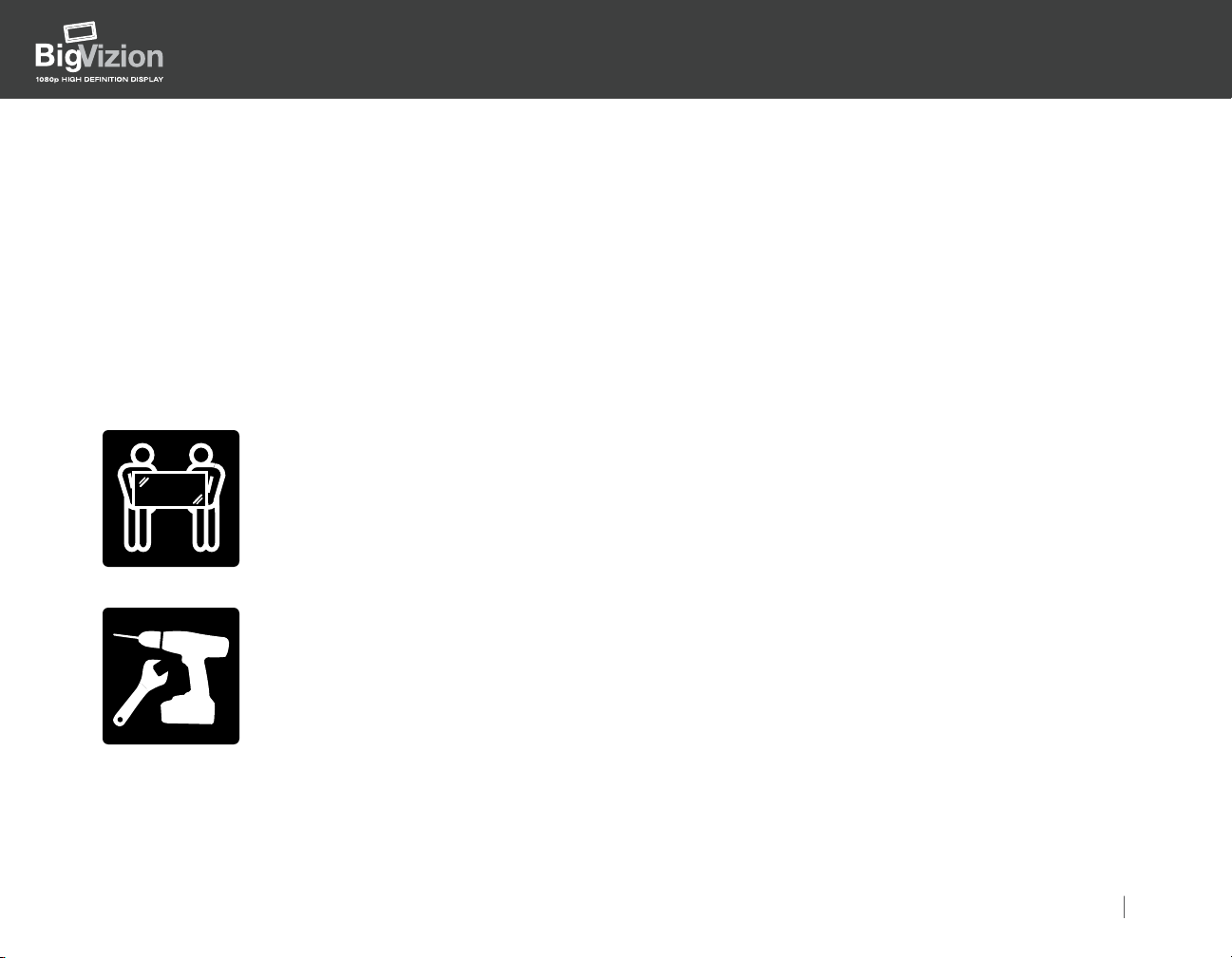
MIRROR HANDLING
The mirror is extremely fragile. Exercise extreme caution when moving.
MIRROR
HANDLING
Mirror weight is ~150 lbs.
TYPICAL TOOLS FOR INSTALL
Installation requires:
1) Power drill
2) 1/2" open-ended wrench and socket set
3) Level
4) Flathead and Philips head screwdriver
5) Utility knife
For more information, please visit our website at:
http://www.optomausa.com/BigVizion
Installation Guide 5
Page 6

Contents
Section I: Preparation for the Installation
1) Position and Placement of the BigVizion
2) Preparing the Wall
3) Shipment of Box 1 (Master Outer Frame) to Job Site
4) Master Outer Frame Assembly
5) Installation of the Master Outer Frame
Section II: Installation of the Frame Components
1) Shipment of the Internal Frame Components to the Job Site
2) Unpacking the Mirror
3) Installation of the Mirror
4) Unpacking of the Base Unit Components
5) Assembly of the Base Unit
6) Installation of the Base Unit
7) Installation of the Screen Frame
8) Installation of the Wood Bezel
Section III: Alignment of the Light Engine
1) Alignment Platform Adjustment Procedure
Installation Guide
HDBV3100, HDBV3090, HDBV3080
Appendix A: Cable Wiring/Connections
1) Cables
2) Connectors
3) Instructions
Appendix B: Discrete IR/RS-232C Codes
1 ) HD3000 RS-232C Protocol Function List
Appendix C: Exploded View of the Product
For more information, please visit our website at:
http://www.optomausa.com/BigVizion
Installation Guide 6
Page 7

Installation Guide
HDBV3100, HDBV3090, HDBV3080
Section I: Preparation for the Installation
1. Position and Placement of the BigVizion
Wall selection is crucial in the BigVizion installation for producing the desired image quality. The BigVizion may
be installed during new home construction or aftermarket remodels. New home construction lends itself to better
placement, since the BigVizion could be implemented during the design phase. Aftermarket installation requires
more detailed thought for its placement. Consider the following guidelines:
1) Select a wall position that does not allow any direct sunlight or lighting
2) Select a wall placement that allows side or rear access for installation
3) Adhere to the minimum wall depths required for installation
For more information, please visit our website at:
http://www.optomausa.com/BigVizion
Installation Guide 7
Page 8
Installation Guide
HDBV3100, HDBV3090, HDBV3080
2. Preparing the Wall
For new home construction, the roughing stage to the final installation may take several months. The BigVizion
packaging has been designed for the master frame (Outer Master Frame) to be installed during the roughing stage.
Follow the listed steps for installation:
Wall Preparation:
Step 1:
The location of the installation will be determined by environmental factors such as wall depth, lighting and ideal
viewing heights.
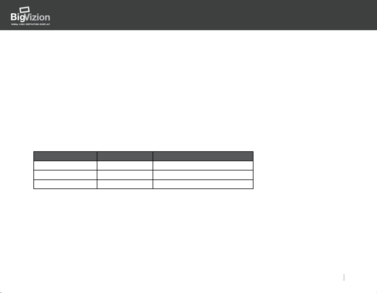
The ideal vertical placement of the BigVizion in the wall opening created, as measured from the floor to the sill
(bottom of the screen) for seated viewing, is as follows:
Model Screen Size Height from seated position
BVHD3100 ~ 20.5"
BVHD3090 ~ 23"
BVHD3080 ~ 25.5"
100"
90"
80"
NOTE: The above are recommendations, the final decision will be determined by the installation professional based
on room and environmental factors.
For more information, please visit our website at:
http://www.optomausa.com/BigVizion
Installation Guide 8
Page 9

Installation Guide
HDBV3100, HDBV3090, HDBV3080
Step 2:
Cut a rough opening through the wall at the correct height, so when finished with the standard 2" x 4" wood framing,
the opening corresponds to the following dimensions:
• BVHD3100 (100"), the rough wall opening must measure at least: 91-11/16" W x 54-13/16" H.
100" BigVizion Wall Opening Diagram. (Figure 1-1)
• BVHD3090 (90"), the rough wall opening must measure at least: 83" W x 50" H.
90" BigVizion Wall Opening Diagram. (Figure 1-2)
• BVHD3080 (80"), the rough wall opening must measure at least: 74-1/4" W x 45" H.
80" BigVizion Wall Opening Diagram. (Figure 1-3)
NOTE: The above listed dimensions are suggested minimums, and can be made slightly larger to accommodate
shim material. Wall must be level on all sides. Check with plumb lines and level.
IMPORTANT!
See the next three diagrams of the 100"/90"/80" for detailed dimensions of required wall opening.
For more information, please visit our website at:
http://www.optomausa.com/BigVizion
Installation Guide 9
Page 10
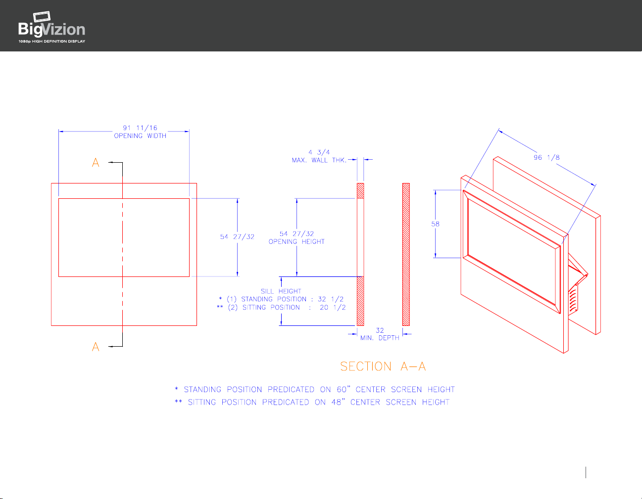
Figure 1-1: 100" BigVizion Wall Opening
Installation Guide
HDBV3100, HDBV3090, HDBV3080
For more information, please visit our website at:
http://www.optomausa.com/BigVizion
Installation Guide 10
Page 11
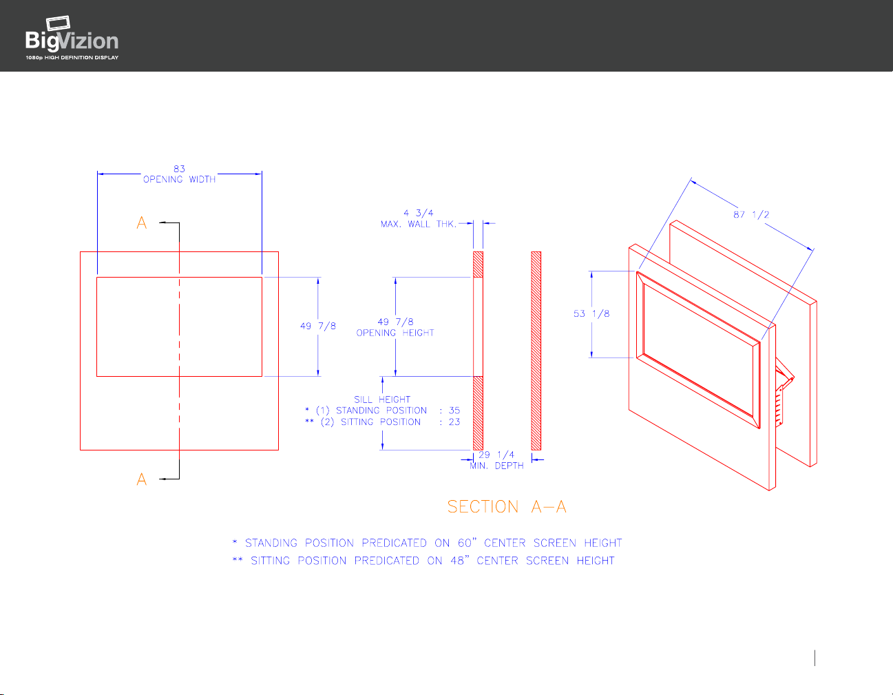
Figure 1-2: 90" BigVizion Wall Opening
Installation Guide
HDBV3100, HDBV3090, HDBV3080
For more information, please visit our website at:
http://www.optomausa.com/BigVizion
Installation Guide 11
Page 12
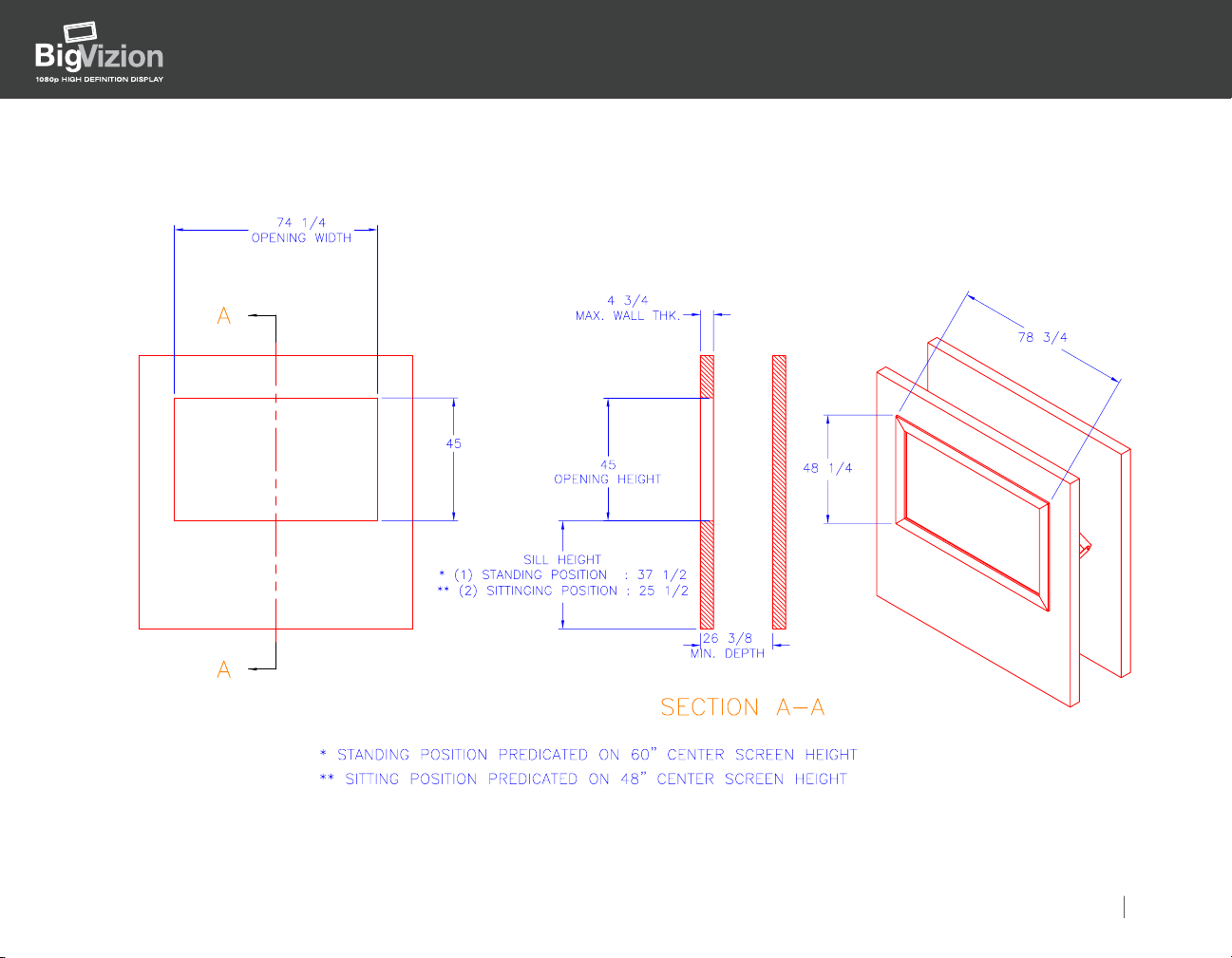
Figure 1-3: 80" BigVizion Wall Opening
Installation Guide
HDBV3100, HDBV3090, HDBV3080
For more information, please visit our website at:
http://www.optomausa.com/BigVizion
Installation Guide 12
Page 13

Installation Guide
HDBV3100, HDBV3090, HDBV3080
3. Shipment of Box 1 (Master Outer Frame)
The master outer frame is located in a knock down box as part of the master BigVizion shipment module. Unscrew
the box from the shipment module and bring to the installation site during the roughing stage of the construction.
Step 1:
Carefully unpack the master outer frame; two vertical and two horizontal pieces.
See Figure 1-4: Box #1 Detail
Notice each piece is marked left, right, top and bottom.
Step 2:
Set aside the hardware pack:
• Eight #10-32 screws and washers
• Twenty-six #8 x 2" Philips dry wall screws
Step 3:
Carefully lay the pieces of the master outer frame on a smooth flat surface and observe the orientation markings.
IMPORTANT! Exercise caution, since the frame is flexible.
See Figure 1-4: Box #1 Detail
For more information, please visit our website at:
http://www.optomausa.com/BigVizion
Installation Guide 13
Page 14
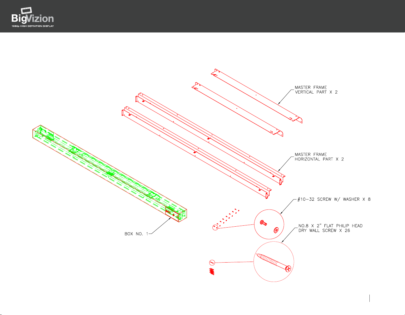
Figure 1-4: Box #1 Detail
Installation Guide
HDBV3100, HDBV3090, HDBV3080
For more information, please visit our website at:
http://www.optomausa.com/BigVizion
Installation Guide 14
Page 15

4. Assembly of the Master Outer Frame
Step 1:
Locate the eight #10-32 screws with washers.
Step 2:
Insert two #10-32 screws with washers on each corner to assemble frames; left, right, top and bottom.
IMPORTANT! See Figure 1-5: Installation of the Master Frame Diagram.
Installation Guide
HDBV3100, HDBV3090, HDBV3080
For more information, please visit our website at:
http://www.optomausa.com/BigVizion
Installation Guide 15
Page 16
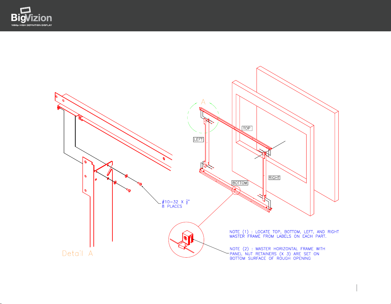
Figure 1-5: Installation of the Master Frame
Installation Guide
HDBV3100, HDBV3090, HDBV3080
For more information, please visit our website at:
http://www.optomausa.com/BigVizion
Installation Guide 16
Page 17

Installation Guide
HDBV3100, HDBV3090, HDBV3080
Installation of the Master Outer Frame into the Wall Opening
Step 1:
With a minimum of two people, carefully raise the master outer frame from the smooth surface while supporting the
frame on the left and right side.
IMPORTANT! Exercise caution when raising the frame.
Step 2:
Position the frame in the wall opening.
Step 3:
Make certain that the frame is positioned, squared and flushed in the wall opening.
Step 4:
Insert the twenty-six #8 x 2" dry wall screws through the holes in the frame and the 2" x 4" wood stud behind the wall.
IMPORTANT! Make certain the frame is flush and square, using plumb lines and carpenters square.
If the frame is not square, the image from projector will not align correctly.
THIS IS THE MOST CRUCIAL PART OF THE INSTALLATION!
See Figure 1-6: Installation of the Master Frame into the Wall Opening
For more information, please visit our website at:
http://www.optomausa.com/BigVizion
Installation Guide 17
Page 18

Figure 1-6: Installation of the Master Frame into the Wall Opening
Installation Guide
HDBV3100, HDBV3090, HDBV3080
For more information, please visit our website at:
http://www.optomausa.com/BigVizion
Installation Guide 18
Page 19

Installation Guide
HDBV3100, HDBV3090, HDBV3080
Section II: Installation of the Frame Components
1. Shipment of the Internal Frame Components to the Job Site
Once the outer master frame has been installed, have the remainder of the framing components available at the
installation site. This includes the internal framing components and all electronics.
2. Unpacking the Mirror
Step 1:
Make certain that there are at least three people available for the unpacking and installation of the mirror.
IMPORTANT! The mirror is heavy ~150lbs.
Step 2:
Remove the front of the crate by removing the screws with the red washers only.
Step 3:
Remove the two wood braces on the left and right side of the mirror that holds the mirror in the crate.
The braces are held in place by two Philips screws on both sides of the mirror.
Step 4:
Carefully remove the mirror from the crate by lifting it slightly up and pulling it straight out.
Step 5:
Carefully set the mirror aside on a smooth surface.
See Figure 2-1: Exploded View of the Mirror and the Frame
For more information, please visit our website at:
http://www.optomausa.com/BigVizion
Installation Guide 19
Page 20

Figure 2-1: Exploded View of the Mirror and the Frame
Installation Guide
HDBV3100, HDBV3090, HDBV3080
For more information, please visit our website at:
http://www.optomausa.com/BigVizion
Installation Guide 20
Page 21

Installation Guide
HDBV3100, HDBV3090, HDBV3080
3. Installation of the Mirror
To install the mirror, have two people lift the mirror, as well as a safety person to guide the mirror. Carefully move the
mirror through either a side opening or a rear opening in the wall behind the master outer frame. Slide the shoulder bolt
that is on the top left side of the mirror through the slot on the left top of master frame, and repeat this with the right side.
See Figure 2-2: Installation of the Mirror Assembly.
Warning! Since the mirror has no support, someone should always hold the mirror in place during installation.
Allow the mirror to gently come towards the front of the wall and remain in a vertical position for the next
installation step.
For more information, please visit our website at:
http://www.optomausa.com/BigVizion
Installation Guide 21
Page 22

Figure 2-2: Installation of the Mirror Assembly.
Installation Guide
HDBV3100, HDBV3090, HDBV3080
For more information, please visit our website at:
http://www.optomausa.com/BigVizion
Installation Guide 22
Page 23

4. Unpacking of Base Unit and Components
Step 1:
Locate Box 2. Refer to Figure 2-3: The Unpacking Diagram.
Step 2:
Remove the screws with red washers, and remove the lid on the crate.
Box 2 contains the following:
• Two mirror stay arms
• Two base hangers
• Two stabilizer arms
• One projector and component base
• One projector light hood
• Two gage alignment blocks
• Twelve 5/16"-18 x 3/4" bolts and nuts
See Figure 2-4: Box 2 Detail
Step 3:
With two people, carefully remove the base unit.
Note that the two wooden blocks are used to prevent the base unit from moving during shipment.
Installation Guide
HDBV3100, HDBV3090, HDBV3080
Step 4:
Remove the screws with red washers that hold the wooden blocks in place.
Step 5:
Lift the base unit out of the crate and set it aside on a smooth surface.
For more information, please visit our website at:
http://www.optomausa.com/BigVizion
Installation Guide 23
Page 24

Installation Guide
HDBV3100, HDBV3090, HDBV3080
Step 6:
Organize the mirror stay arms, base hangers, stabilizer arms, gage blocks and hardware.
Step 7:
Locate the two mirror stay arms. Note the orientation arrow for this end up, as well as the one end marked S to
denote pointing towards the screen or front of the wall.
Step 8:
Working from inside the wall space, attach the front of the mirror stay arm (S) towards the screen/wall to the bottom
portion of the master outer frame. Use two 5/16-18 x 3/4" screws for the left stay arm and the right stay arm.
Step 9:
The curve side of mirror stay arm points up. Observe the arrow on both stay arms.
Step 10:
Refer back to Figure 1-2.
IMPORTANT! Make certain the mirror stay arms are attached with the (S) pointing towards the screen, or the front
of the wall, oriented from inside the wall space.
Step 11:
Carefully raise the mirror towards the back of the wall. Using two 5/16-18 x 3/4" screws and nuts, attach the rear
mirror stay arms to the mirror.
IMPORTANT! Have three people available to hold the mirror in position and to attach the mirror stay arms.
Refer back to Figure 1-2.
For more information, please visit our website at:
http://www.optomausa.com/BigVizion
Installation Guide 24
Page 25

Figure 2-3: The Unpacking Diagram
Installation Guide
HDBV3100, HDBV3090, HDBV3080
For more information, please visit our website at:
http://www.optomausa.com/BigVizion
Installation Guide 25
Page 26

Figure 2-4: Box 2 Detail
Installation Guide
HDBV3100, HDBV3090, HDBV3080
For more information, please visit our website at:
http://www.optomausa.com/BigVizion
Installation Guide 26
Page 27

Installation Guide
HDBV3100, HDBV3090, HDBV3080
5. Assembly of the Base Unit
Step 1:
Locate the base unit and the two base hangers that were set aside. (Refer back to Figure 2-4: Box 2 Detail.)
Step 2:
Carefully lift the bottom of the base unit by lifting the left and right side. Attach the base hangers as shown in
Figure 2-5: Installation of the Projector Base.
(Note the orientation of the base hangers; (S) for towards the front/screen and (M) towards the back/mirror.)
Step 3:
With at least two people, lift the base unit, position it in to the wall below the mirror and align the base hangers
directly under the mirror stay arms for later attachment.
For more information, please visit our website at:
http://www.optomausa.com/BigVizion
Installation Guide 27
Page 28

6. Installation of the Base Unit
Step 1:
Working from the front of the wall opening with a minimum of two people, carefully raise the base unit.
Step 2:
Position the base hangers to the outside of the mirror stay arms.
Step 3:
Insert four 5/16-18 x ¾" screws with washers through the two middle holes on the mirror stay arms.
Note: Washers need to be inserted on both the inside and outside of the mirror stay arms.
Step 4:
Insert and tighten the nuts on the 5/16-18 x ¾" screws.
See Figure 2-5: Installation of the Projector Base.
Installation Guide
HDBV3100, HDBV3090, HDBV3080
For more information, please visit our website at:
http://www.optomausa.com/BigVizion
Installation Guide 28
Page 29

Installation Guide
HDBV3100, HDBV3090, HDBV3080
Figure 2-5: Installation of the Projector Base.
For more information, please visit our website at:
http://www.optomausa.com/BigVizion
Installation Guide 29
Page 30

HDBV3100, HDBV3090, HDBV3080
7. Installation of the Screen Frame
Step 1:
Locate box 3 that the mirror was removed from. (Refer back to the master crate.)
Step 2:
Remove the two side panels that attach box 3 to the bottom of the crate. (Necessary to access box 4)
Step 3:
On the left and right side panel, only remove the screws with red washers that secures box 3 to the master crate.
Step 4:
Carefully remove box 3 from the crate and set it aside; it is no longer needed.
Step 5:
Remove the lid on box 4 by removing all the screws with red washers.
(Referring to Figure 2-3: The Unpacking Diagram.)
Step 6:
Box 4 contains both the screen frame assembly and the wood bezel.
Installation Guide
Step 7:
Carefully separate the screen frame assembly from the bezel and move it towards the front of the master outer frame.
Step 8:
Carefully unwrap the protective paper around the screen frame.
For more information, please visit our website at:
http://www.optomausa.com/BigVizion
Installation Guide 30
Page 31

Installation Guide
Step 9:
The screen frame has two sides. The back side has ridges and circles; while the front side is smooth with a plastic wrap.
Step 10:
Notice that the screen frame has two pins on each side; the left and right.
Step 11:
If you are facing the front of the outer master frame, it has a hole on the top left side and a slot on the top right side.
Step 12:
With two people, lift the screen frame up with the glossy side facing out. Align the pin on the top left side first, and
slide in. Match it with the hole on the left side of the master outer frame. The third person will help guide the pin
alignment. With the other pin, match the right side of the screen frame with the slot on the right side of the master
outer frame.
See Figure 2-6: Installation of the Screen.
HDBV3100, HDBV3090, HDBV3080
For more information, please visit our website at:
http://www.optomausa.com/BigVizion
Installation Guide 31
Page 32

Figure 2-6: Installation of the Screen
Installation Guide
HDBV3100, HDBV3090, HDBV3080
For more information, please visit our website at:
http://www.optomausa.com/BigVizion
Installation Guide 32
Page 33

Installation Guide
HDBV3100, HDBV3090, HDBV3080
8. Installation of the Wood Bezel
Locate the wood bezel that was set aside during the screen frame assembly. Use the following steps to install the bezel.
Step 1:
With two people, carefully orient the wood bezel vertically.
Step 2:
Align the six grabber catches, the female part of the bezel clip and the male part of the main frame.
Step 3:
Position the bezel so the bottom arrows on the bezel align with the bottom arrows on the master outer frame. Push in
the bottom of the bezel until the catches lock. Once the bottom of the bezel is aligned and locked, push the top of the
bezel until it locks.
See Figure 2-7: Installation of the Wood Bezel.
For more information, please visit our website at:
http://www.optomausa.com/BigVizion
Installation Guide 33
Page 34

Figure 2-7: Installation of the Wood Bezel
Installation Guide
HDBV3100, HDBV3090, HDBV3080
For more information, please visit our website at:
http://www.optomausa.com/BigVizion
Installation Guide 34
Page 35

Installation Guide
HDBV3100, HDBV3090, HDBV3080
Section III: Alignment of the Light Engine
ALIGNMENT PLATFORM ADJUSTMENT PROCEDURE
Use the Video Essentials or Avia Test DVD for alignment patterns.
Step 1:
Using two gage blocks for initial positioning, adjust the alignment platform (AP) until the bottom of AP surface contacts
the gage blocks and the rear edge of both the AP and the projection base (PB) contacts the corners of the gage blocks.
See Figure 3-1: Setting the Gage on “0” Position.
Step 2:
Remove the gage blocks and fine tune the image per Figures 3-2, 3-3, 3-4, 3-5, 3-6 and 3-7.
For more information, please visit our website at:
http://www.optomausa.com/BigVizion
Installation Guide 35
Page 36

Figure 3-1: Setting the Gage on “0” Position
Installation Guide
HDBV3100, HDBV3090, HDBV3080
For more information, please visit our website at:
http://www.optomausa.com/BigVizion
Installation Guide 36
Page 37

Problem: Solution:
(Vertical Keystone) Turn knobs #1 & 4 together in the same direction.
Figure 3-2: Vertical Keystone Adjustment
VERTICAL
KEYSTONE
Installation Guide
HDBV3100, HDBV3090, HDBV3080
For more information, please visit our website at:
http://www.optomausa.com/BigVizion
Installation Guide 37
Page 38

Problem: Solution:
(Horizontal Keystone) Turn knobs #3 & 4 together in the same direction.
Figure 3-3: Horizontal Keystone Adjustment
HORIZONTAL
KEYSTONE
Installation Guide
HDBV3100, HDBV3090, HDBV3080
For more information, please visit our website at:
http://www.optomausa.com/BigVizion
Installation Guide 38
Page 39

Problem: Solution:
(Skewed Image) Turn knobs #5 & 6 in opposite directions.
Figure 3-4: Skewed Image Adjustment
SKEWED
PICTURE
Installation Guide
HDBV3100, HDBV3090, HDBV3080
For more information, please visit our website at:
http://www.optomausa.com/BigVizion
Installation Guide 39
Page 40

Problem: Solution:
(Image Shift Vertically) Turn knobs #5 & 6 in the same direction.
Figure 3-5: Image Shift Vertically Adjustment
IMAGE SHIFT
VERTICALLY
Installation Guide
HDBV3100, HDBV3090, HDBV3080
For more information, please visit our website at:
http://www.optomausa.com/BigVizion
Installation Guide 40
Page 41

Problem: Solution:
(Image Shift Horizontally) Loosen the four Philips head screws just enough to manually
shift AP to the left or right and then tighten the screws.
Figure 3-6: Image Shift Horizontally Adjustment
IMAGE SHIFT
HORIZONTALLY
Installation Guide
HDBV3100, HDBV3090, HDBV3080
For more information, please visit our website at:
http://www.optomausa.com/BigVizion
Installation Guide 41
Page 42

Problem: Solution:
(Image Sizing) Turn knobs #1, 2, 3 & 4 in the same direction.
Figure 3-7: Image Sizing Adjustment
IMAGE
SIZING
Installation Guide
HDBV3100, HDBV3090, HDBV3080
For more information, please visit our website at:
http://www.optomausa.com/BigVizion
Installation Guide 42
Page 43

Appendix A: Cable Wiring/Connections
Cables:
Installation Guide
HDBV3100, HDBV3090, HDBV3080
For more information, please visit our website at:
http://www.optomausa.com/BigVizion
Installation Guide 43
Page 44

Connectors:
Ballast Cable
Installation Guide
HDBV3100, HDBV3090, HDBV3080
For more information, please visit our website at:
http://www.optomausa.com/BigVizion
Installation Guide 44
Page 45

Connectors: (Continued)
Installation Guide
HDBV3100, HDBV3090, HDBV3080
For more information, please visit our website at:
http://www.optomausa.com/BigVizion
Installation Guide 45
Page 46

Installation Guide
HDBV3100, HDBV3090, HDBV3080
Instructions:
Connectors SC2, SC3, SC7, SC10 and SC11 are connected at the factory. To connect the rest of the cables, follow
the procedures below.
NOTE: Cables 3 through 7 each have two different ends and only fit in their proper locations in one orientation.
Do not force any of the cables in if they do not fit. Doing so may damage the cables and/or their respective housings.
1) Connect Cable 1 from the DVI slot SC12 on the system command board to the DVI slot LE2 on the light engine.
2) Connect Cable 2 from the HDMI slot SC1 on the system command board to the HDMI out slot on the HD3000.
3) Connect Cable 3 from the 12V trigger plug SC6 on the system command board to the 12V trigger plug on the HD3000.
4) Connect Cable 4 from the 14-pin plug SC4 on the system command board to the power plug LE1on the light engine.
5) Connect Cable 5 from the fan power plug SC8 on the system command board to the power cable LE6 on the lamp fan.
6) Connect Cable 6 from the fan power plug SC9 on the system command board to the power cable LE3 on the DMD fan.
7) Connect Cable 7 from the thermal switch plug SC5 on the system command board to the thermal switch cable LE5.
8) Connect the ballast cable to the lamp power plug LE4 and screw it down.
The schematics of these connections can be found on the next page.
For more information, please visit our website at:
http://www.optomausa.com/BigVizion
Installation Guide 46
Page 47

Installation Guide
System Command Board
HDMI
14-pin
DVI
TS
12V
Fan1
Fan2
HD3000
HDMI out
12V
L/E Bottom
LE
Power
DVI
DMD
Fan
Engine Side
TS
Lamp
Fan
Cable 1
Cable 2
Cable 3
Cable 4
Cable 5
Cable 6
Cable 7
HDBV3100, HDBV3090, HDBV3080
For more information, please visit our website at:
http://www.optomausa.com/BigVizion
Installation Guide 47
Page 48

Appendix B: Discrete IR/RS-232C Codes
HD3000 RS-232C Protocol Function List
Installation Guide
HDBV3100, HDBV3090, HDBV3080
Interface
3 wires RS-232C Protocol
Baud Rate : 57600
Data Bits: 8
Parity: None
Stop Bits: 1
Flow Control :None
Command Sequence
Write
Header :
Address Code :
Command Code :
Data :
Terminator Code :
Basic Protocol
‘*’
‘0’ fixed
ASCII Text
Fixed 3 digits
Carriage Return
Acknowledgement
Receive OK ( in standby mode)
Receive OK ( in normal mode )
Invalid Command
*000<CR>
*010<CR>
*001<CR>
Function List
Power On
Power Off
Menu
Up
Down
Left
Right
Enter
Re-Sync
Source-CVB1
Source-CVB2
Source-CVB3
Source-S Video1
Source-S Video2
Source-S Video3
Source-YPbPr1
Source-YPbPr2
Source-BNC1
Source-BNC2
Basic Protocol
Function Description Basic(Original) Basic (Update)
*0IR001<CR>
*0IR002<CR>
*0IR003<CR>
*0IR004<CR>
*0IR005<CR>
*0IR006<CR>
*0IR007<CR>
*0IR008<CR>
*0IR009<CR>
*0IR010<CR>
*0IR011<CR>
*0IR012<CR>
*0IR013<CR>
*0IR014<CR>
*0IR015<CR>
*0IR016<CR>
*0IR017<CR>
*0IR018<CR>
*0IR019<CR>
For more information, please visit our website at:
http://www.optomausa.com/BigVizion
Installation Guide 48
Page 49

HD3000 RS-232C Protocol Function List (Continued)
Installation Guide
HDBV3100, HDBV3090, HDBV3080
Source-HDMI1
Source-HDMI2
Source-HDMI3
Source-VGA
Aspect Ratio- 16:19
Aspect Ratio- 4:3
Aspect Ratio- Native
Aspect Ratio- Format1
Aspect Ratio- Format2
Aspect Ratio- Format3
Model-ISF Day
Model-ISF Night
Mode-User1
Mode-User2
Mode-User3
Zoom In
Zoom Out
Shift Up
Shift Down
Gamma
Image Mode
NR
Sharpness
Color
Contrast
Function Description Basic(Original) Basic (Update)
*0IR020<CR>
*0IR021<CR>
*0IR022<CR>
*0IR023<CR>
*0IR024<CR>
*0IR025<CR>
*0IR026<CR>
*0IR027<CR>
*0IR028<CR>
*0IR029<CR>
*0IR030<CR>
*0IR031<CR>
*0IR032<CR>
*0IR033<CR>
*0IR034<CR>
*0IR035<CR>
*0IR036<CR>
*0IR037<CR>
*0IR038<CR>
*0IR039<CR>
*0IR040<CR>
*0IR041<CR>
*0IR042<CR>
*0IR043<CR>
*0IR044<CR>
For more information, please visit our website at:
http://www.optomausa.com/BigVizion
Installation Guide 49
Page 50

Appendix C: Exploded View of the Product
Installation Guide
HDBV3100, HDBV3090, HDBV3080
For more information, please visit our website at:
http://www.optomausa.com/BigVizion
Installation Guide 50
Page 51

Installation Guide
HDBV3100, HDBV3090, HDBV3080
For more information, please visit our website at:
http://www.optomausa.com/BigVizion
Installation Guide 51
Page 52

USA
715 Sycamore Drive
Milpitas, CA 95035
Tel: 408-383-3700
Fax: 408-383-3702
www.optomausa.com
Canada
5630 Kennedy Road
Mississauga, ON, L4Z 2A9
Tel: 905-882-4228
Fax: 905-882-4229
www.optoma.ca
Optoma Technology, Inc.
715 Sycamore Drive, Milpitas, CA 95035 · Tel: (408) 383-3700 · Fax: (408) 383-3702
Specifications subject to change without notice. Copyright © 2006 Optoma Technology, Inc. All rights reserved.
 Loading...