

Page 1

1
English
Table of Contents
Table of Contents ............................1
Usage Notice ...................................2
Safety Information ...............................2
Precautions .........................................3
Eye Safety Warnings ..........................6
Flexible Angle Setting .........................6
Introduction ......................................7
Package Overview ..............................7
Product Overview ...............................8
Main Unit ..............................................8
Input/Output Connections .................... 9
Remote Control ..................................10
Installation ..................................... 11
Connecting the Projector .................. 11
Connect to Computer/Notebook ........ 11
Connect to Video Sources ................. 12
Connect to 3D Video Devices ...........13
Using the 3D glasses ........................15
Powering On/Off the Projector ..........16
Powering On the Projector .................16
Powering Off the Projector .................17
Warning Indicator ...............................18
Adjusting the Projected Image ..........19
Adjusting the Projector’s Height ........ 19
Adjusting the Projector’s Position ...... 20
User Controls ................................22
Control Panel & Remote Control ......22
Control Panel ..................................... 22
Remote Control ..................................23
On-screen Display Menus ................25
How to operate ..................................25
Menu Tree .......................................... 26
IMAGE ............................................... 28
IMAGE | Advanced ............................ 30
IMAGE | Advanced | PureEngine ....... 31
IMAGE | Advanced | Color Settings ... 32
DISPLAY ............................................ 34
DISPLAY | 3D ................................... 39
SYSTEM ............................................ 40
SETUP ............................................... 43
SETUP | HDMI Link Settings ............. 45
SETUP | Signal (VGA) ....................... 47
SETUP | Signal (Video) ..................... 48
Appendices ....................................49
Troubleshooting ................................49
Image Problems ................................. 49
Other Problems .................................. 51
Remote Control Problems .................51
LED Lighting Messages ..................... 52
On Screen Messages ........................ 53
Compatibility Modes .........................54
RS232 Commands and Protocol
Function List .....................................56
RS232 Pin Assignments .................... 56
RS232 Protocol Function List ............ 57
Ceiling Mount Installation ..................60
Optoma Global Ofces .....................61
Regulation & Safety Notices .............63
FCC Notice ........................................ 63
Declaration of Conformity for EU
countries ............................................ 64
Trademarks .......................................65
Page 2
2
English
Usage Notice
Safety Information
The lightning ash with arrow head within an equilateral triangle is
intended to alert the user to the presence of uninsulated “dangerous volt-
age” within the product’s enclosure that may be of sufcient magnitude to
constitute a risk of electric shock to persons.
The exclamation point within an equilateral triangle is intended to alert
the user to the presence of important operating and maintenance (servicing) instructions in the literature accompanying the appliance.
WARNING: TO REDUCE THE RISK OF FIRE OR ELECTRIC SHOCK, DO NOT
EXPOSE THIS APPLIANCE TO RAIN OR MOISTURE. DANGEROUS HIGH
VOLTAGES ARE PRESENT INSIDE THE ENCLOSURE. DO NOT OPEN THE
CABINET. REFER SERVICING TO QUALIFIED PERSONNEL ONLY.
Class B emissions limits
This Class B digital apparatus meets all requirements of the Canadian
Interference-Causing Equipment Regulations.
Important Safety Instruction
1. Do not block any ventilation openings. To ensure reliable operation of the projector
and to protect from over heating, it is recommended to install the projector in a location that does not block ventilation. As an example, do not place the projector on a
crowded coffee table, sofa, bed, etc. Do not put the projector in an enclosure such
as a book case or a cabinet that restricts air ow.
2. Do not use the projector near water or moisture. To reduce the risk of re and/or
electric shock, do not expose the projector to rain or moisture.
3. Do not install near heat sources such as radiators, heaters, stoves or any other apparatus such as ampliers that emits heat.
4. Clean only with dry cloth.
5. Only use attachments/accessories specied by the manufacturer.
6. Do not use the unit if it has been physically damaged or abused. Physical damage/
abuse would be (but not limited to):
Unit has been dropped. -
Power supply cord or plug has been damaged. Liquid has been spilled on to the projector. Projector has been exposed to rain or moisture. -
Something has fallen in the projector or something is loose inside. Do not attempt to service the unit yourself. Opening or removing covers
may expose you to dangerous voltages or other hazards. Please call
Optoma before you send the unit for repair.
7. Do not let objects or liquids enter the projector. They may touch dangerous voltage
points and short out parts that could result in re or electric shock.
8. See projector enclosure for safety related markings.
9. The unit should only be repaired by appropriate service personnel.
Page 3
3
English
Usage Notice
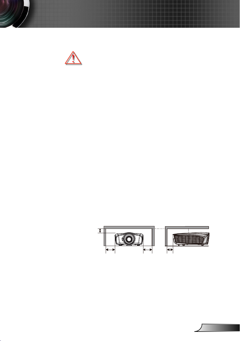
8” (20cm) 4” (10cm)
8” (20cm)
4” (10cm)
Precautions
Please follow all warnings, precautions and maintenance as recommended in this user’s guide.
▀■ Warning-
▀■ Warning-
▀■ Warning-
▀■ Warning-
▀■ Warning-
▀■ Warning-
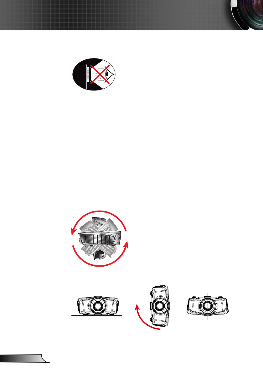
Do not look into the projector’s lens when the
LED is on. The bright light may hurt your eyes.
To reduce the risk of re or electric shock, do
not expose this projector to rain or moisture.
Please do not open or disassemble the projector as this may cause electric shock.
When switching the projector off, please ensure
the cooling cycle has been completed before
disconnecting power. Allow 10 seconds for the
projector to cool down.
Do not use lens cap when projector is in opera-
tion.
Allowing the proper amount of space on the
top, sides, and rear of the projector cabinet is
critical for proper air circulation and cooling of
the unit. The dimensions shown here indicate
the minimum space required. If the projector
is to be built into a compartment or similarly
enclosed, these minimum distances must be
maintained.
Page 4

4
English
Usage Notice
Do:
Turn off and unplug the power plug from the AC outlet before
cleaning the product.
Use a soft dry cloth with mild detergent to clean the display hous-
ing.
Disconnect the power plug from AC outlet if the product is not be-
ing used for a long period of time.
Do not:
Block the slots and openings on the unit provided for ventilation.
Use abrasive cleaners, waxes or solvents to clean the unit.
Use under the following conditions:
In extremely hot, cold or humid environments. -
Ensure that the ambient room temperature is within 5°C ~ `
40°C
Relative humidity is 10% ~ 85% `
In areas susceptible to excessive dust and dirt. Near any appliance generating a strong magnetic eld. In direct sunlight. -
Viewing 3D projection using the 3D function
IMPORTANT SAFETY INFORMATION. READ THE FOLLOWING WARNINGS BEFORE YOU OR YOUR CHILD USE THE 3D FUNCTION.
Warning
Children and teenagers may be more susceptible to health issues
associated with viewing in 3D and should be closely supervised
when viewing these images.
Photosensitive Seizure Warning and Other Health Risks
Some viewers may experience an epileptic seizure or stroke when
exposed to certain ashing images or lights contained in certain
Projector pictures or video games. If you suffer from, or have a
family history of epilepsy or strokes, please consult with a medical
specialist before using the 3D function.
Even those without a personal or family history of epilepsy or
stroke may have an undiagnosed condition that can cause photosensitive epileptic seizures.
Pregnant women, the elderly, sufferers of serious medical condi-
Page 5

5
English
Usage Notice
tions, those who are sleep deprived or under the inuence of
alcohol should avoid utilizing the unit’s 3D functionality.
If you experience any of the following symptoms, stop viewing 3D
pictures immediately and consult a medical specialist: (1) altered
vision; (2) light-headedness; (3) dizziness; (4) involuntary movements such as eye or muscle twitching; (5) confusion; (6) nausea;
(7) loss of awareness; (8) convulsions; (9) cramps; and/ or (10)
disorientation. Children and teenagers may be more likely than
adults to experience these symptoms. Parents should monitor
their children and ask whether they are experiencing these symptoms.
Watching 3D projection may also cause motion sickness, percep-
tual after effects, disorientation, eye strain and decreased postural
stability. It is recommended that users take frequent breaks to
lessen the potential of these effects. If your eyes show signs of
fatigue or dryness or if you have any of the above symptoms, immediately discontinue use of this device and do not resume using
it for at least thirty minutes after the symptoms have subsided.
Watching 3D projection while sitting too close to the screen for
an extended period of time may damage your eyesight. The
ideal viewing distance should be at least three times the screen
height. It is recommended that the viewer’s eyes are level with the
screen.
Watching 3D projection while wearing 3D glasses for an extended
period of time may cause a headache or fatigue. If you experience
a headache, fatigue or dizziness, stop viewing the 3D projection
and rest.
Do not use the 3D glasses for any other purpose than for watch-
ing 3D projection. Wearing the 3D glasses for any other purpose
(as general spectacles, sunglasses, protective goggles, etc.) may
be physically harmful to you and may weaken your eyesight.
Viewing in 3D projection may cause disorientation for some view-
ers. Accordingly, DO NOT place your 3D PROJECTOR near open
stairwells, cables, balconies, or other objects that can be tripped
over, run into, knocked down, broken or fallen over.
Page 6
6
English
Usage Notice
360°
90°
Eye Safety Warnings
▀■ Avoid staring/facing directly into the projector beam at all
times. Keep your back to the beam as much as possible.
▀■ When projector is used in a classroom, adequately supervise
students when they are asked to point out something on the
screen.
▀■ In order to minimize the lamp power, use room blinds to re-
duce ambient light levels.
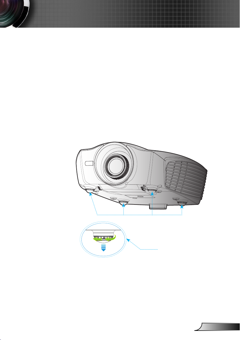
Flexible Angle Setting
▀■ Available angle in vertial direction
▀■ Available angle in horizontal direction
Page 7
7
English
Introduction
Menu
Mode
16:9 4:3
Letter-Box Native
Pure Engine
3D Format
LED Brightness
HDMI
Link
2D/3D
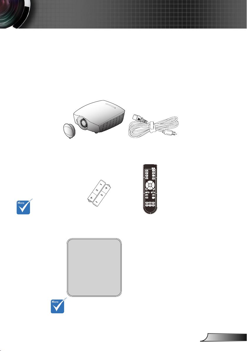
Package Overview
Unpack and inspect the box contents to ensure all parts listed
below are in the box. If something is missing, please contact
Optoma customer service.
Projector with lens cap
Due to different
applications in
each Country,
some regions may
have different
accessories.
2 × AAA Batteries
Documentation :
Warranty Card
Quick Start Card
WEEE Card
(for EMEA only)
For European warranty information please visit www.optomaeurope.com
Power Cord
IR Remote Control
(Remote may vary de-
pending on model)
Page 8
8
English
Introduction
3D SYNC
Out 5V
5V PWR
Out 6W
( )
( )
3D SYNC
Out 5V
5V PWR
Out 6W
( )
( )
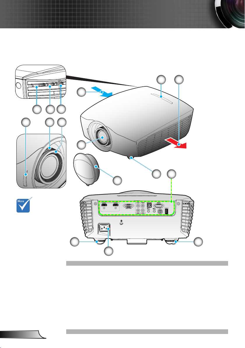
Product Overview
Main Unit
4
6
5
1 2
5
7 8
The interface is
subject to model’s
specications.
Do not block
projector in/out air
vents.
3
9
11
12
10
11 11
13
Power Button / Power 1.
LED
Temp LED2.
Source Button3.
Ventilation (inlet)4.
IR Receivers5.
Ventilation (outlet)6.
Zoom Ring7.
Focus Ring8.
Lens9.
Lens Cap10.
Tilt-Adjustment Feet11.
Input / Output 12.
Connections
Power Socket13.
Page 9
9
English
Introduction
3D SYNC
Out 5V
5V PWR
Out 6W
( )
( )
3D SYNC
Out 5V
5V PWR
Out 6W
( )
( )
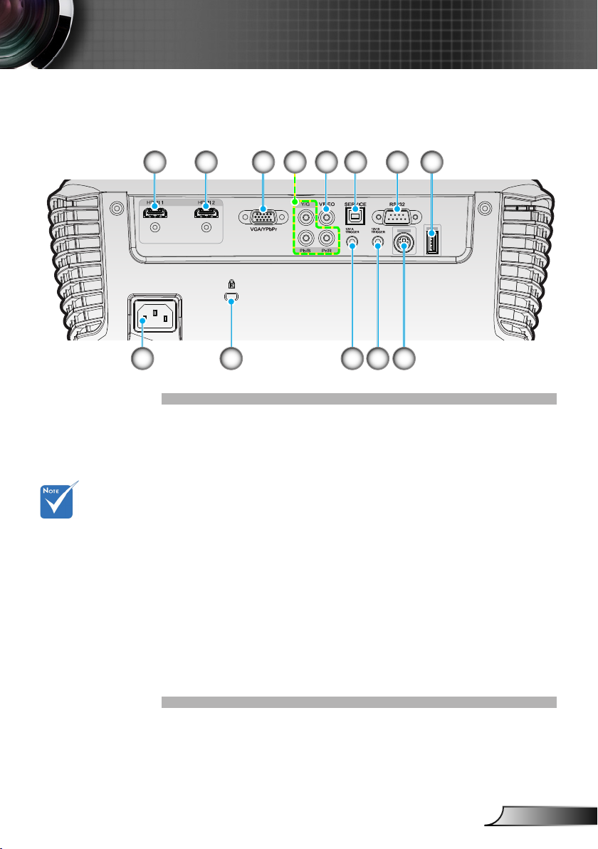
Input/Output Connections
9
The interface is
subject to model’s
specications.
1 2 3 5 6 7
10
4 8
12 13
11
HDMI 1 Connector (v1.4a 3D supported)1.
HDMI 2 Connector (v1.4a 3D supported)2.
VGA-In/YPbPr Connector 3.
(PC Analog Signal/Component Video Input/HDTV/YPbPr)
Component Video Input Connector (YPbPr)4.
Composite Video Input Connector5.
USB for rmware upgrade6.
RS-232 Connector (9-pin)7.
USB for Power (5V@1A)8.
Power Socket9.
Kensington10.
TM
Lock Port
12V Trigger A Relay Connector (12V, 250mA. 3.5mm Mini 11.
Jack)
12V Trigger B Relay Connector (12V, 250mA. 3.5mm Mini 12.
Jack)
3D Sync Out (5V)13.
Page 10
10
English
Introduction
Menu
Mode
16:9 4:3
Letter-Box Native
Pure Engine
3D Format
LED Brightness
HDMI
Link
2D/3D
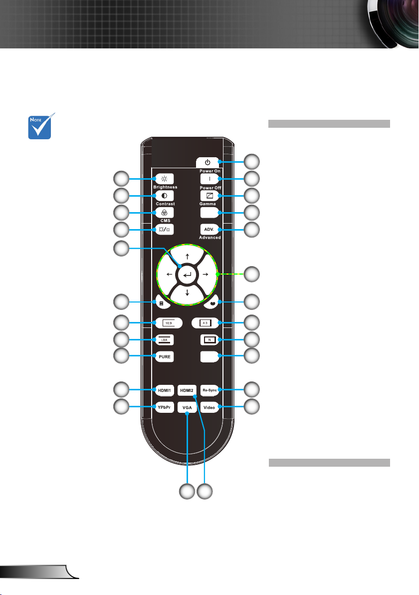
Remote Control
The remote is
subject to model’s
specications.
25
24
23
22
21
19
17
16
15
10
11
12
Power On1.
Power Off2.
1
2
3
4
Gamma3.
HDMI Link4.
Advanced5.
Four Directional Select 6.
Keys
Mode7.
5
4:38.
Native9.
3D format10.
6
Re-Sync11.
Video Source12.
HDMI2 Source13.
720
8
918
VGA Source14.
YPbPr Source15.
HDMI1 Source16.
PureEngine17.
LBX18.
16:919.
Menu20.
Enter21.
LED Brightness22.
CMS (Color Manage-23.
ment System)
Contrast24.
Brightness25.
14 13
Page 11
11
English
Installation
3D SYNC
Out 5V
5V PWR
Out 6W
( )
( )
3D SYNC
Out 5V
5V PWR
Out 6W
( )
( )
mol ex
MOLEX
E62405SP
R
Connecting the Projector
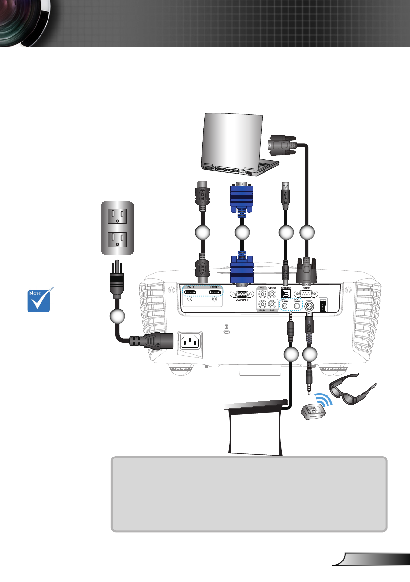
Connect to Computer/Notebook
2 3
Due to the
difference in
applications for
each country,
some regions may
have different
accessories.
(*) Optional
accessory
1
6547
+12V Output
3D Glasses
1....................................................................................................Power Cord
2..................................................................................................*HDMI Cable
3................................................................................................... *VGA Cable
4....................................................................................................*USB Cable
5................................................................................................*RS232 Cable
6................................................................................................ *12V DC Jack
7...........................................................................................*3D Emitter cable
Page 12
12
English
Installation
3D SYNC
Out 5V
5V PWR
Out 6W
( )
( )
3D SYNC
Out 5V
5V PWR
Out 6W
( )
( )
E62405SP
R
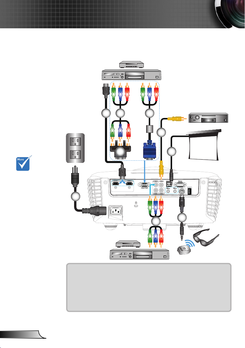
Connect to Video Sources
DVD Player, Set-top Box,
HDTV receiver
2 4
Composite Video Output
5
6
Due to the
difference in applications for each
country, some
regions may have
different accessories.
For more detailed
information about
connecting to the
3D emitter and 3D
glasses, please
refer to their
user’s guides.
Use high speed
HDMI cable to
connect Blu-ray
3D player.
(*) Optional Ac-
cessory
3
7
+12V Output
1
4
DVD Player, Set-top Box,
HDTV receiver
8
3D Glasses
1....................................................................................................Power Cord
2..................................................................................................*HDMI Cable
3........................................................................................*VGA/RCA Adaptor
4.............................................................................*3 RCA Component Cable
5...........................................................................................*VGA/RCA Cable
6................................................................................*Composite Video Cable
7................................................................................................ *12V DC Jack
8...........................................................................................*3D Emitter cable
Page 13
13
English
Installation
The 3D video
NOTE
NOTE
source device
must be powered
on before the 3D
projector.
If input video is
normal 2D, please
press “3D Format”
and switch to
“AUTO”.
If “SBS Mode” is
active, 2D video
content will not
display correctly.
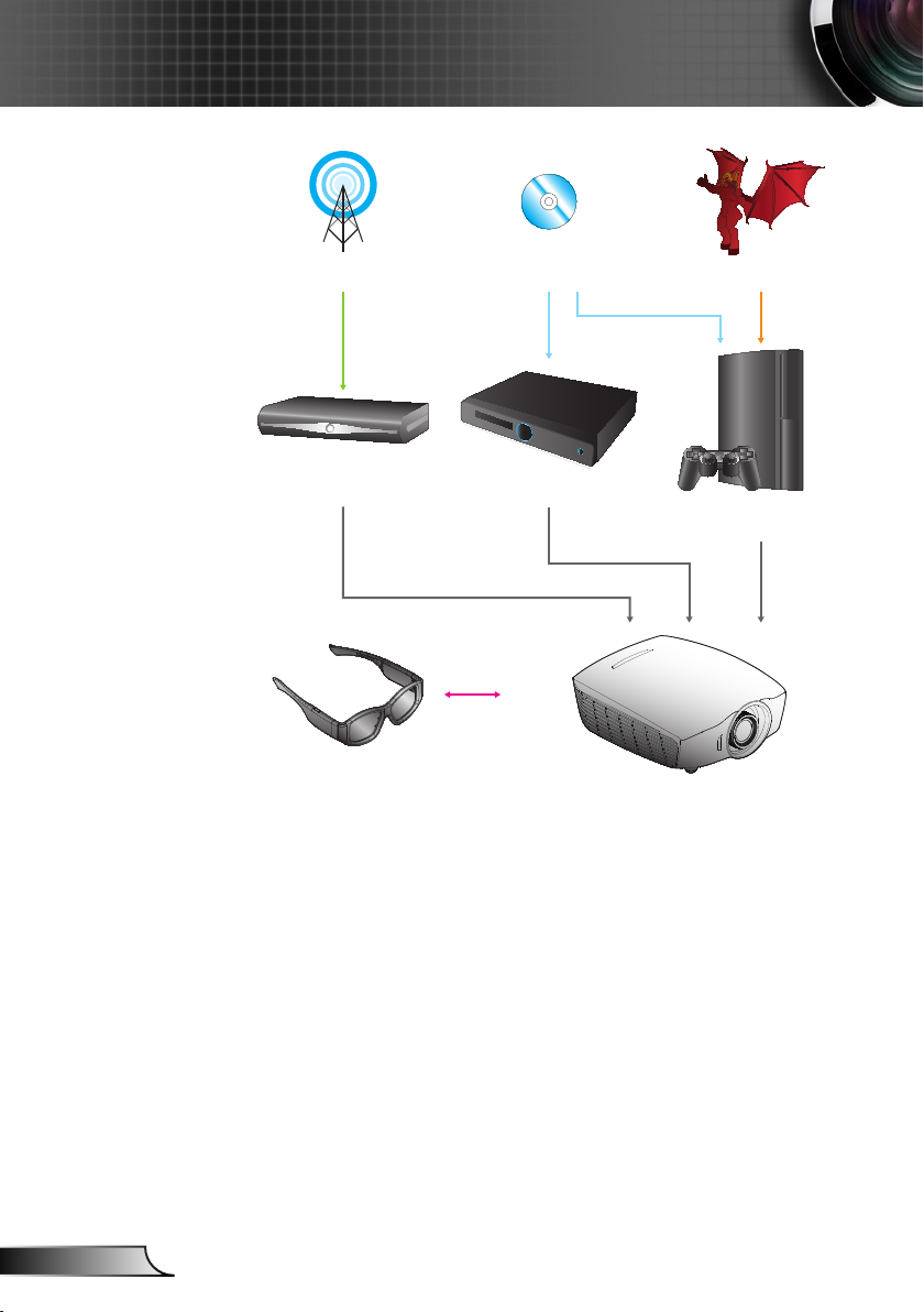
Connect to 3D Video Devices
Once you have connected your devices together with HDMI
cables, as shown in the diagram, you are ready to begin.
Power ON your 3D video source and your 3D projector.
PlayStation® 3 Games
Make sure that you have updated your console to the latest software ver- y
sion.
Go to the “Settings menu -> Display settings -> Video output -> HDMI”. y
Select “Automatic” and follow the on-screen instructions.
Insert your 3D game disc. Alternatively you can download games (and 3D y
updates) via the PlayStation® network.
Launch the game. In the in-game menu, select “Play in 3D”. y
Blu-ray 3D™ Player
Make sure that your player can support 3D Blu-ray™ disc and that 3D y
output is enabled.
Insert the 3D Blu-ray™ disc into the player, press “Play”. y
3D TV (e.g. SKY 3D, DirecTV)
Contact your TV service provider to enable any 3D channels on your y
channel package.
Once enabled, switch to the 3D channel. y
You should see two images side-by-side. y
Switch to the “SBS Mode” of the 3D projector. The option is located in the y
“DISPLAY” section of the projector OSD menu.
3D Device (e.g. 3D DV/DC) with 2D 1080i side by side signal output
Connect your 3D device and switch to out 3D content with 2D side-by-side y
output to 3D Projector.
You should see two images side-by-side. Switch to the “SBS Mode” of the 3D projector. The option is located in the y
“DISPLAY” section of the projector OSD menu.
If watching 3D content from an HDMI 1.4a source (e.g. 3D Blu-ray) your 3D
glasses should always be in sync. If watching 3D content from an HDMI 1.3
source (e.g. 3D broadcast using SBS mode) it may be necessary to use the
projector’s 3D Sync-Invert option to optimize your 3D experience. The option
is located in the “DISPLAY ->3D” section of the projector OSD menu.
Page 14
14
English
Installation
3D Broadcast 3D Blu-ray™ Disc 3D Console Games
SKY+HD, cable/satellite
box
3D Glasses
3D Blu-ray™ Player
PlayStation® 3
Full 3D 1080p DLP® Projector
Page 15

15
English
Installation
For more detailed
NOTE
information,
please refer to
3D glasses user’s
guide.
Using the 3D glasses
To turn ON 3D glasses: Press the “Power” button and the LED will ash 1.
one time indicating the glasses are ready to use 3D mode.
Verify that 3D content is being sent to the projector and signal is compat-2.
ible with projector specications.
Turn on the “3D Mode” of the 3D projector. The option is located in the 3.
“DISPLAY” section of the projector OSD menu.
Turn on 3D glasses and verify image appears in 3D without eyestrain.4.
If the image does not appear in 3D, please check 3D device set up cor-5.
rectly to send out 3D image or not. Or “SBS Mode” should turn on when
input signal is 2D 1080i side-by-side and repeat previous steps 1 ~ 4.
It may be necessary to use projector’s “3D Sync. Invert” option to optimize 6.
your 3D experience. The option is located in the “DISPLAY” section of the
projector OSD menu.
To turn OFF 3D glasses: Press the “Power” button and hold until the LED 7.
switches off.
For more detailed information, please refer to the 3D glasses user’s 8.
guide, or manufacturer's Website.
Page 16
16
English
Installation
Powering On/Off the Projector
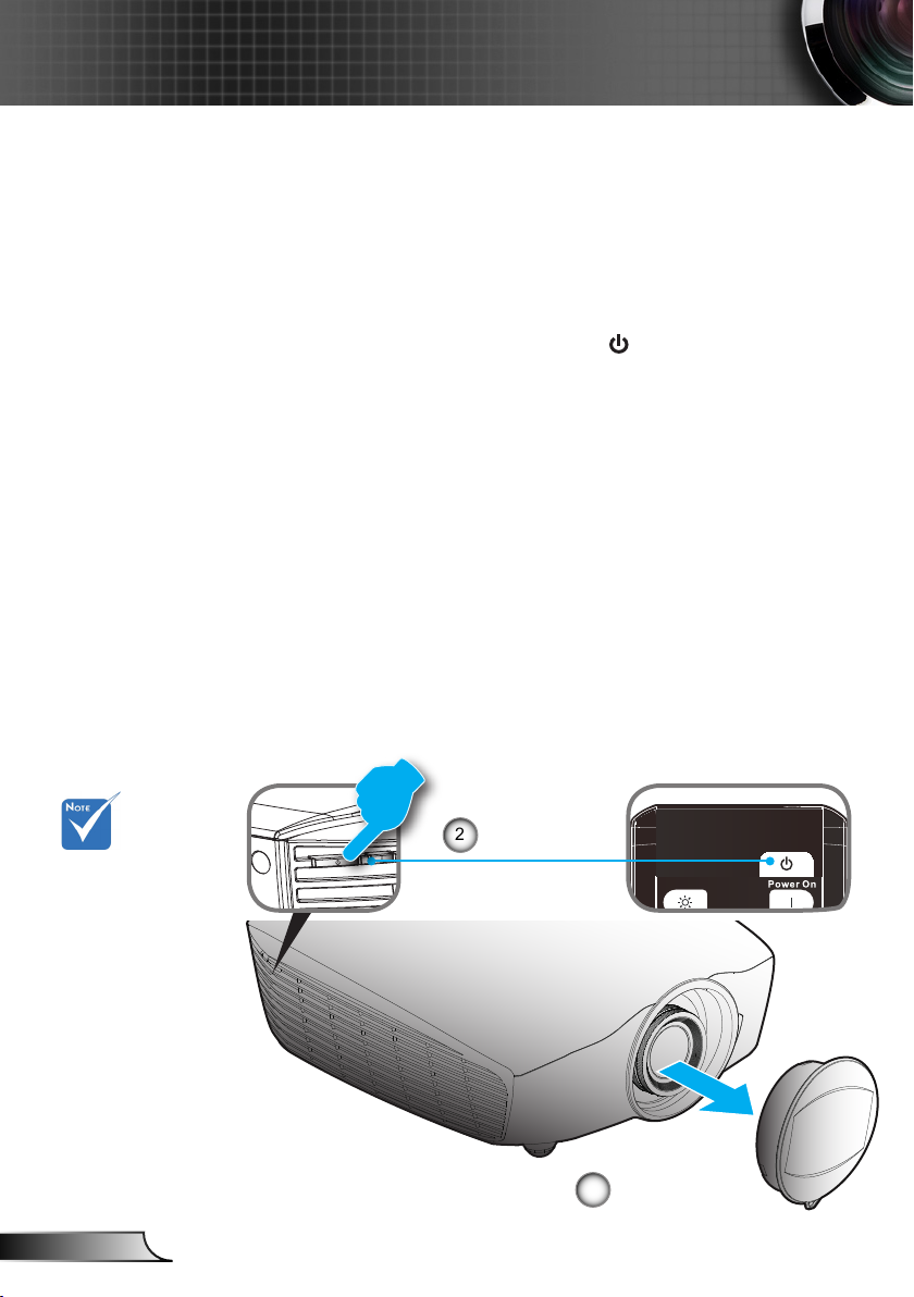
Powering On the Projector
1. Remove the lens cap.
2. Securely connect the power cord and signal cable. When
connected, the Power LED will turn red.
3. Turn on the projector by pressing “ ” button either on the
side of the projector or on the remote. The Power LED will
now turn blue.
The startup screen will display in approximately 10 seconds.
The rst time you use the projector, you will be asked to
select the preferred language.
4. Turn on and connect the source that you want to display
on the screen (computer, notebook, video player, etc). The
projector will detect the source automatically. If not, push
menu button and go to “SETUP”.
Make sure that the “Source Lock” has been set to “Off”.
If you connect multiple sources at the same time, press the
“SOURCE” button on the control panel or the direct source
keys on the remote control to switch between inputs.
Turn on the projec-
tor rst and then
select the signal
sources.
2
Power
1
Lens Cap
Page 17

17
English
Installation
Powering Off the Projector
1. Press the “ ” button on the remote control or “
” button on the side of the projector two times
with one second interval to turn off the projector.
The following message will be displayed on the screen.
Power off?
Press power key again
Press the “ ” button again to conrm otherwise the
message will disappear after 15 seconds. When you press
the “ ” button for the second time, the projector will shut
down.
2. The cooling fans continue to operate for about 10 seconds
for cooling cycle and the Power LED will ash blue. When
the Power LED lights solid red, the projector has entered
standby mode.
If you wish to turn the projector back on, you must wait
until the projector has completed the cooling cycle and
has entered standby mode. Once in standby mode, simply
press “ ” button to restart the projector.
3. Disconnect the power cord from the electrical outlet and
the projector.
4. Do not turn on the projector immediately following a power
off procedure.
Page 18

18
English
Installation
Warning Indicator
When the warning indicators (see below) come on,
the projector will automatically shutdown:
Contact the nearest
service center if the
projector displays
these symptoms.
See pages 61-62 for
more information.
“Power” LED indicator ashes red.
“TEMP” LED indicator is lit red and if “Power” LED indicator
ashes red. This indicates the projector has overheated.
Under normal conditions, the projector can be switched
back on.
“TEMP” LED indicator ashes red and if “Power” LED
indicator ashes red.
Unplug the power cord from the projector, wait for 30 seconds
and try again. If the warning indicator light up again, please
contact your nearest service center for assistance.
Page 19
19
English
Installation
Adjusting the Projected Image
Adjusting the Projector’s Height
The projector is equipped with elevator feet for adjusting
the image height.
1. Locate the adjustable foot you wish to modify on the
underside of the projector.
2. Rotate the adjustable ring clockwise to raise the projector
or counter clockwise to lower it. Repeat with the remaining
feet as needed.
Tilt-Adjustment Feet
Tilt-Adjustment Ring
Page 20
20
English
Installation
10%W 10%W
60%H
60%H
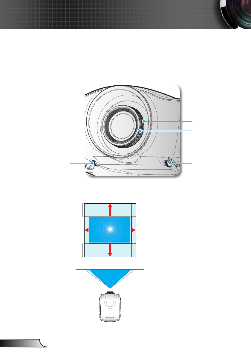
Adjusting the Projector’s Position
To determine where to position the projector, consider the size and
shape of your screen, the location of your power outlets, and the distance between the projector and the rest of your equipment.
Zoom Ring
Focus Ring
Horizontal Lens
Shift Lever
Width(W)
Vertical Lens
Shift Lever
Height (H)
Page 21

21
English
Installation
This table is for
user’s reference
only.
Projection distance:
From screen to lens.
Lens
Optoma Model Name Wide version Tele Version
Focal Length (f) (mm) 18.07~22.59 22.56~42.87
F number 2.0~2.32 2.3~3.39
Zoom Range (Ratio) 1.25 1.90
Zoom & Focus Adjustment Manual
Motorized Lens Shift Horizontal : +/-10%, Vertical : +/-60%
Wide version Tele Version
Screen size Projection Distance (mm)
(inch) Wide Tele Wide Tele
40 1065 1335 1310 2555
50 1335 1680 1650 3205
60 1610 2020 1995 3860
70 1885 2365 2335 4510
80 2160 2705 2680 5165
90 2430 3045 3020 5815
100 2705 3390 3365 6470
150 4075 5100 5080 9730
180 4901 6137 6105 11684
200 5445 6810 6790 12995
250 6810 8520 8505 16255
300 8180 10230 10215 19520
350 9550 11940 11930 22780
400 10920 13650 13640 26040
450 12285 15360 15350 29305
500 13655 17070 17065 32565
Page 22

22
English
User Controls
Control Panel & Remote Control
Control Panel
Using the Control Panel
Power Button /
Power LED
Temp LED
SOURCE
Refer to the “Power On/Off the Projector” section on pages 16-17.
Indicate the projector’s status.
Indicate the projector’s temperature status.
Press “SOURCE” to select an input signal.
Page 23

23
English
User Controls
Menu
Mode
16:9 4:3
Letter-Box Native
Pure Engine
3D Format
LED Brightness
HDMI
Link
2D/3D
Remote Control
Using the Remote Control
Power On
Power Off
Gamma
HDMI Link
Advanced
Four
Directional
Select Keys
Mode
4:3
Native
3D Format
Re-Sync
Video
Turn on the projector.
Turn off the projector.
Set up gamma curve type.
Enables and disables the HDMI link function.
Display or exit the “IMAGE | Advanced”
menu.
Use directional select keys to select items or
make adjustments to your selection.
Select a display mode for optimised settings
for different applications. (refer to page 28)
Scale the image at a 4:3 (1440x1080) aspect
ratio.
The input source will be displayed without
scaling.
Manually select a 3D mode that matches
your 3D content.
Automatically synchronizes the projector to
the input source.
Press “Video” to choose Composite video
source.
HDMI2
VGA
YPbPr
Press “HDMI2” to choose source from
HDMI 2 connector.
Press “VGA” to choose source from
VGA-In/YPbPr connector.
Press “YPbPr” to choose source from YPbPr
connector.
Page 24

24
English
User Controls
Menu
Mode
16:9 4:3
Letter-Box Native
Pure Engine
3D Format
LED Brightness
HDMI
Link
2D/3D
Using the Remote Control
HDMI1
Press “HDM1” to choose source from
HDMI 1 connector.
The PureEngine is a collection of advanced
PureEngine
image processing technologies that enhances the quality of the displayed image.
Enable the viewing of the letterboxed nonan-
LBX
amorphically enhanced movie at full screen
width. Part of the original image will be lost if
the image aspect ratio is less than 2.35:1.
16:9
Menu
Enter
LED Brightness
Scale the image at a 16:9 (1920x1080)
aspect ratio.
Display or exit the on-screen display menus
for projector.
Conrm your item selection.
Increase/Decrease the luminance of the image. (refer to page 30)
CMS (Color
Manage-
ment Sys-
Select one of the colors (R/G/B/ C/M/Y) to
adjust its x/y offset and brightness.
tem)
Contrast
Brightness
Control the degree of difference between the
lightest and darkest parts of the picture.
Adjust the brightness of the image.
Page 25

25
English
User Controls
On-screen Display Menus
The Projector has multilingual On-screen Display menus that
allow you to make image adjustments and change a variety of
settings. The projector will automatically detect the source.
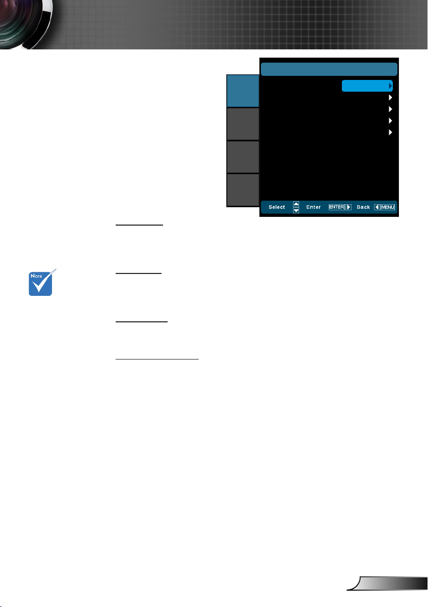
How to operate
1. To open the OSD menu, press “Menu” on the Remote Control or
Control Panel.
2 When OSD is displayed, use ▲▼ keys to select any item in the
main menu. While making a selection on a particular page, press
► or “Enter” key to enter sub menu.
3. Use ▲▼ keys to select the desired item in the sub menu and then
press ► or “Enter” key to view further settings. Adjust the settings
by ◄► key.
4. Select the next item to be adjusted in the sub menu and adjust as
described above.
5. Press “Enter” or “Menu” to conrm, and the screen will return to
the main menu.
6. To exit, press “Menu” again. The OSD menu will close and the
projector will automatically save the new settings.
Main Menu
IMAGE
DISPLAY
SYSTEM
SETUP
Sub Menu
IMAGE
Display Mode
Contrast
Brightness
Sharpness
Color
Tint
Advanced
Cinema
0
0
0
0
0
0
Setting
Page 26

26
English
User Controls
Menu Tree
Main Menu Sub Menu Settings
IMAGE Display Mode Cinema / Film / Reference / Photo / Bright / 3D /
Contrast -50~50
Brightness -50~50
Sharpness 0~15
#1
Color -50~50
#1
Tint -50~50
Advanced Noise Reduction 0~10
DISPLAY Format 4:3 / 16:9 / LBX / Native / Auto235 / Auto235_Subtitle
SYSTEM Menu Location
Zoom 0~10
Edge Mask 0~5
Image Shift H -100~100
V Keystone -30~30
3D 3D Format AUTO / SBS / Top and Bottom / Frame Sequential
LED Hours
Projection
Gamma Film / Video / Graphics / Standard
PureEngine UltraDetail / PureColor / PureMotion /
LED Brightness Power / DynamicBlack 1 / DynamicBlack 2 /
Color Settings Color Temperature / Color Gamut / CMS /
Exit
V -100~100
3D -> 2D 3D / L / R
2D -> 3D Low / Middle / High
#2
3D Sync. Invert On / Off
Exit
ISF Day / ISF Night / User
PureEngine Demo / Exit
DynamicBlack 3
RGB Gain/Bias / Color Space / RGB Channel
/ 2D -> 3D
Test Pattern Off / Grid / White
Background Color Blue / Gray / Black
IR Function All / Front / Top
12V Trigger A On / Off
12V Trigger B Off
Anamorhic Lens None / Fixed / Movable
On 4:3 / 16:9 / LBX / Native / Exit
Auto 3D
Exit
Page 27

27
English
User Controls
Main Menu Sub Menu Settings
SETUP Language
Input Source HDMI 1 / HDMI 2 / Component / VGA / Video / Exit
HDMI Link Settings HDMI Link On / Off
Source Lock On / Off
High Altitude On / Off
Information Hide On / Off
Auto Power Off (min) 0~180
Signal Frequency 0~100
Reset Current Cancel / Yes
Please note that the on-screen display (OSD) menus vary according to the
signal type selected and the projector model you are using.
( #1) “Color” and “Tint” are only supported in Video mode.
( #2) “3D Sync. Invert” is only available when 3D is enabled.
Inclusive of TV Yes / No
Power On Link Mutual / PJ -> Device / Device -> PJ
Power Off Link On / Off
Phase -50~50
H. Position -50~50
V. Position -50~50
Automatic Enable / Disable
Exit
White Level -50~50
Black Level -50~50
Saturation -50~50
Hue -50~50
IRE 0 IRE / 7.5 IRE
Exit
All Cancel / Yes
Page 28

28
English
User Controls
IMAGE
Display Mode
There are many factory presets optimized for various types of
images.
Cinema: Default settings for home theater. `
Reference: This mode is intended to reproduce, as close as `
“ISF Day” and
“ISF Night” will
not be shown
when the ISF
modes have not
been calibrated.
possible, the image the way the movie director intended. Color,
color temperature, brightness, contrast and gamma settings are
all congured to standard reference levels.
Film: The purest color settings for home theater. `
Photo: Optimized for displaying photographic images. `
Bright: Maximum brightness from PC input. `
3D: Recommended setting for 3D mode enabled. Any further `
adjustments by the user in 3D will be saved in this mode for
further use.
ISF Day: Optimize the image with the ISF Day mode to be per- `
fectly calibrated and high picture quality.
ISF Night: Optimize the image with the ISF Night mode to be `
perfectly calibrated and high picture quality.
User: User’s settings. `
Contrast
The contrast controls the degree of difference between the lightest
and darkest parts of the picture.
Press the ◄ to decrease the contrast. `
Press the ► to increase the contrast. `
Brightness
Adjust the brightness of the image.
Press the ◄ to darken image. `
Press the ► to lighten the image. `
Sharpness
Adjust the sharpness of the image.
IMAGE
DISPLAY
SYSTEM
SETUP
IMAGE
Display Mode
Contrast
Brightness
Sharpness
Color
Tint
Advanced
Cinema
0
0
0
0
0
0
Page 29

29
English
User Controls
“Color” and “Tint”
are only supported for composite
and component
sources.
Press the ◄ to decrease the sharpness. `
Press the ► to increase the sharpness. `
Color
Adjust a video image from black and white to fully saturated color.
Press the ◄ to decrease the color saturation in the image. `
Press the ► to increase the color saturation in the image. `
Tint
Adjust the color balance of red and green.
Press the ◄ to increase the amount of green in the image. `
Press the ► to increase the amount of red in the image. `
Page 30

30
English
User Controls
IMAGE | Advanced
Noise Reduction
The Noise Reduction reduces the amount of visible noise interlaced signals. The range is from “0” to “10”. (0: Off)
Gamma
This allows you to set up gamma curve type. After the initial setup
and ne tuning is completed, utilize the Gamma Adjustment steps
to optimize your image output.
Film: for home theater. `
Video: for video or TV source. `
Standard: for standardized setting. `
Graphics: for PC / Photo source. `
PureEngine
The PureEngine is a collection of advanced image processing
technologies that enhances the quality of the displayed image.
LED Brightness
Power: Manually adjust the LED brightness (100%~50%). `
DynamicBlack 1: Automatically adjusts the LED brightness `
between 100% ~ 13%.
DynamicBlack 2: Automatically adjusts the LED brightness `
between 100% ~ 5%.
DynamicBlack 3: Automatically adjusts the LED brightness `
between 100% ~ 0%.
Color Settings
Press ► into the next menu and then use ▲ or ▼ to select item.
IMAGE
DISPLAY
SYSTEM
SETUP
IMAGE |
ADVANCED
Noise Reduction
Gamma
PureEngine
LED Brightness
Color Settings
Exit
0
Standard
100%
Page 31
31
English
User Controls
IMAGE | Advanced
| PureEngine
UltraDetail
UltraDetail is an edge enhancement tool that enables the edges in
the projected image is be enhanced thus providing more per-
ceived detail.
PureColor
This adjustable item utilizes a new color-processing algorithm and
Turn the PureMotion
feature to “Off” to
reduce the response
lag during gameplay.
enhancements to enable the picture’s vividness to be signicantly
increased. The range is from “0” to “5”.
PureMotion
PureMotion uses sophisticated algorithms to ensure that the natural motion in the image is preserved.
PureEngine Demo
This feature enables you to see the difference in the image quality
between the raw unprocessed image and the image processed as
processed by the PureEngine. Use this mode to check the adjustments that you make to the PureEngine settings.
IMAGE
DISPLAY
SYSTEM
SETUP
IMAGE | ADVANCED |
UltraDetail
PureColor
PureMotion
PureEngine Demo
Exit
PureEngine
Off
Off
Off
Off
Page 32

32
English
User Controls
IMAGE | Advanced
| Color Settings
Color Temperature
Select a color temperature from D50, D65, D75, D83, D93 and
Native.
Color Gamut
Select an appropriate color gamut from Native, Adobe, DLP-C,
HDTV, or SMPTE-C.
CMS (Color Management System)
Press ► into the next menu and then use ▲ or ▼ to select item.
Select one of the colors (R/G/B/C/M/Y) to adjust its x/y offset and
brightness.
CMS
Color
x Offset
y Offset
Brightness
Reset
Exit
Color Gamut : DLP-C
0
0
0
Red
IMAGE
DISPLAY
SYSTEM
SETUP
IMAGE | ADVANCED |
Color Temperature
Color Gamut
CMS
RGB Gain/Bias
Color Space
RGB Channel
Exit
Color Settings
D65
Adobe
Auto
Normal
Color: Use ◄ or ► to select from Red, Green, Blue, Cyan, `
Magenta or Yellow colors.
x Offset: Use ◄ or ► to adjust the x offset value of selected `
color.
y Offset: Use ◄ or ► to adjust the y offset value of selected `
color.
Brightness: Use ◄ or ► to adjust the brightness value of `
selected color.
Reset: Choose “Yes” to return the factory default settings for `
color adjustments.
Page 33

33
English
User Controls
RGB Gain/Bias
Press ► into the next menu and then use ▲ or ▼ to select item.
RGB Gain/Bias
Red Gain
IMAGE
DISPLAY
SYSTEM
SETUP
Green Gain
Blue Gain
Red Bias
Green Bias
Blue Bias
Reset
Exit
Use ◄ or ► to select Red, Green, or Blue for brightness `
(Gain) and contrast (Bias).
Reset: Choose “Yes” to return the factory default settings for `
color adjustments.
Color Space
Select an appropriate color matrix type from AUTO, RGB(0-255),
RGB(16-235) or YUV.
RGB Channel
Use ◄ or ► to select from Normal, Red, Green or Blue channels.
0
0
0
0
0
0
Page 34

34
English
User Controls
DISPLAY
Format
(#1) This function is
not supported in the
movable or xed of
anamorphic lens.
(#2) This function is
only supported when
System/Anamorphic
Lens is Fixed or Movable.
Use this function to choose your desired aspect ratio.
4:3: This format is for 4x3 input sources. `
16:9: This format is for 16x9 input sources, like HDTV and `
DVD enhanced for Widescreen TV.
LBX: This format is for non-16x9, letterbox source and for us- `
ers who use external anamorphic lens to display 2.35:1 aspect
ratio using full resolution.
(#1)
Native `
ing.
Auto235 `
format.
Auto235_Subtitle `
12v trigger will send power to the anamorphic lens if the
source format is 2.35:1. It will not send the power when the
source format is 4:3 or 16:9.
DISPLAY
16:9
0
0
0
IMAGE
DISPLAY
SYSTEM
SETUP
Format
Zoom
Edge Mask
Image Shift
V Keystone
3D
: This format displays the original image without scal-
(#2)
: Automatically selects the appropriate display
(#2)
: When Auto235 feature is selected the
HDMI
2D/HQFS/2D->3D
SBS
Top and Bottom
1080p24FP
720pFP
Auto235 OFF
4:3 16:9 LBX Native
Page 35

35
English
User Controls
HDMI
2D/HQFS/2D->3D
SBS
Top and Bottom
1080p24FP
720pFP
Auto235 ON
4:3 16:9 LBX Auto235
Auto235
subtitle
Pressing “Native”
button on the remote
will be “Auto235” when
Anamorphic lens is
xed or movable.
Component
2D/HQFS/2D->3D
SBS
Top and Bottom
Component
2D/HQFS/2D->3D
SBS
Top and Bottom
4:3 16:9 LBX Native
4:3 16:9 LBX Auto235
Auto235 OFF
Auto235 ON
Auto235
subtitle
Detail informations about LBX mode:
Some Letter-Box Format DVDs are not enhanced for 16x9 1.
TVs. In this situation, the image will not look right when displayed in 16:9 mode. In this situation, please try to use the 4:3
mode to view the DVD. If the content is not 4:3, there will be
black bars around the image in 16:9 display. For this type of
content, you can use LBX mode to ll the image on the 16:9
display.
If you use an external anamorphic lens, this LBX mode also 2.
allows you to watch a 2.35:1 content (include Anamorphic
DVD and HDTV lm source) that support anamorphic wide
is enhanced for 16x9 Display in a wide 2.35:1 image. In this
case, there are no black bars. LED power and vertical resolution are fully utilized.
Page 36

36
English
User Controls
16:9 Screen 480i/p 576i/p 1080i/p 720p PC
(#1) This function is
not supported in SBS
mode.
Pressing “Native”
button on the remote
will be “Auto235” when
Anamorphic lens is
xed or movable.
Each I/O has dif-
ferent setting of
“Edge Mask”.
4:3 1440 x 1080 center
16:9 1920 x 1080 center
(#1)
LBX
Native
Auto235
16:9 Screen 480i/p 576i/p 1080i/p 720p PC
4:3 1440 x 1080 center
16:9 1920 x 1080 center
(#1)
LBX
(#1)
Auto235
(same button on
remote of Native)
Auto235_Subtitle
No anamorphic lens attached
1080p Scaling Table
1920 x 1440 center, then get the central 1920 x 1080
image to display
No resize image, 1:1 mapping and centered. This format
shows original image without scaling.
If this format is select, Screen type will auto become 16:9
(1920x1080)
If source is 4:3, auto resize to 1440 x1080
If source is 16:9 auto resize to 1920x1080
If source is 16:10 auto resize to 1920 x 1200 and cut
1920x1080 area to display
When anamorphic lens is movable
Catch
720x363
(Center)
Catch
720x436
(Center)
Catch
1920x817
(Center)
Catch
1920x545
(Center)
Catch
75.65% of
height
(Center)
Scale to 1920x1440, then get the central 1920x1080 im-
age to display
When source is 2.35:1(with black bar at top/bottom), Do-
ing LBX format.
When source isn’t 2.35:1 that is full 4x3 or 16x9 (There is
no black bar at top/bottom), doing 16x9 format
Catch
720x422
(bottom)
Catch
720x506
(bottom)
Catch
1920x948
(bottom)
Catch
1920x632
(bottom)
Catch
87.8% of
height
(bottom)
When source is 2.35:1(with black bar at top/bottom), Do-
ing above catching rule and Scale to 1920x1440, then get
the central 1920x1080 image to display.
When source isn’t 2.35:1 that is full size 4x3 or 16x9
(There is no black bar at top/bottom), doing 16x9 format
Page 37

37
English
User Controls
When anamorphic lens is xed
16:9 Screen 480i/p 576i/p 1080i/p 720p PC
4:3 1080 x 1080 center
16:9 1440 x 1080 center
(#1)
LBX
(#1)
Auto235
(same button on
remote of Native)
Auto235_Subtitle
Catch
720x363
(Center)
Scale to 1920x1440, then get the central 1920x1080 im-
When source is 2.35:1(with black bar at top/bottom), Do-
When source isn’t 2.35:1 that is full 4x3 or 16x9 (There is
Catch
720x422
(bottom)
When source is 2.35:1(with black bar at top/bottom), Do-
ing above catching rule and Scale to 1920x1440, then get
(There is no black bar at top/bottom), doing 16x9 format
Catch
720x436
(Center)
Catch
1920x817
(Center)
Catch
1920x545
(Center)
75.65% of
(Center)
age to display
ing LBX format.
no black bar at top/bottom), doing 16x9 format
Catch
720x506
(bottom)
Catch
1920x948
(bottom)
Catch
1920x632
(bottom)
87.8% of
(bottom)
the central 1920x1080 image to display.
When source isn’t 2.35:1 that is full size 4x3 or 16x9
Catch
height
Catch
height
Edge Mask
Edge mask the image to remove video encoding noise on the
edge of video source.
Zoom
Press the ◄ to reduce the size of an image. `
Press the ► to magnify an image on the projection screen. `
Image Shift
Press ► into the next menu as below and then use ▲ or ▼or ◄
or ►to select item.
Page 38

38
English
User Controls
H: Press the ◄ ► to shift the projected image position hori- `
zontally.
V: Press the ▲ ▼ to shift the projected image position verti- `
cally.
V Keystone
Press the ◄ or ► to adjust image distortion vertically and make a
squarer image.
Image Shift
H: 0
V: 0
Page 39

39
English
User Controls
DISPLAY | 3D
“3D Sync. Invert”
function wouldn’t save
the setting. It will set to
“Off” when powers on
and changes source.
3D Format is only sup-
ported on 3D Timing
on page 55.
“3D Format” is only
supported on non-
HDMI 1.4a 3D timing.
IMAGE
DISPLAY
SYSTEM
SETUP
DISPLAY |
3D Format
3D -> 2D
2D -> 3D
3D Sync. Invert
Exit
3D
3D -> 2D
3D: Display 3D signal. `
L (Left): Display the left frame of 3D content. `
R (Right): Display the right frame of 3D content. `
2D -> 3D
Select 3D depth of eld (or strength) from Low, Middle or High.
3D Format
Auto: Display the native format. `
SBS: Display 3D signal in “Side-by-Side” format. `
Top and Bottom: Display 3D signal in “Top and Bottom” format. `
Frame Sequential: Display 3D signal in “Frame Sequential” `
format.
2D -> 3D: 2D signal transform 3D signal `
3D Sync. Invert
Press the “On” to invert left and right frame contents. `
Press the “Off” for default frame contents. `
3D
Middle
Off
Page 40

40
English
User Controls
Rear-Desktop and
Rear-Ceiling are to be
used with a translucent screen.
SYSTEM
Menu Location
IMAGE
SYSTEM
DISPLAY
SYSTEM
SETUP
LED Hours
Projection
Test Pattern
Background Color
IR Function
12V Trigger A
12V Trigger B
Anamorhic Lens
Menu Location
Choose the menu location on the display screen.
LED Hours
Display the LED time.
Projection
` Front-Projection
This is the default selection. The image is projected straight on
the screen.
` Rear-Desktop
When selected, the image will appear reversed.
FW:B01
0
Off
Black
All
On
Off
None
` Front-Ceiling
When selected, the image will turn upside down.
` Rear-Ceiling
When selected, the image will appear reversed in upside down
position
Test Pattern
Display a test pattern. There are Grid, White pattern and Off.
Background Color
Use this feature to display a “Black”, “Blue”, or “Gray” screen
when no signal is available.
IR Function
All: Choose “All”, the projector can be operated by the remote `
control from front or top IR receiver.
Front: Choose “Front”, the projector can be operated by the `
remote control from front IR receiver.
Page 41

41
English
User Controls
(#1) When the mov-
able lens is selected,
this item will be gray
out and become
“Auto235”.
Top: Choose “Top”, the projector can be operated by the re- `
mote control from top IR receiver.
12V Trigger A
12V trigger A provides a standard trigger for motorized screens.
12V Trigger B
Press the “Off” to disable the trigger. `
Press the “On” to enable the trigger and the programmable `
sub-menu. The sub-menu is accessed by selecting the “On”
option then pressing the “Enter” button on the remote control.
Checking an option in the sub-menu will activate the trigger
when the corresponding display mode is selected. For the example, 4:3 has been selected – this means that Trigger B will
be active when the projector display mode is set to 4:3. The
trigger will be inactive for all the other display mode options.
(#1)
IMAGE
DISPLAY
SYSTEM
SETUP
IMAGE
DISPLAY
SYSTEM
SETUP
SYSTEM |
Off
On
Auto235
Auto 3D
Exit
SYSTEM |
Off
On
Auto235
Auto 3D
Exit
IMAGE
DISPLAY
SYSTEM
SETUP
SYSTEM |
4:3
16:9
LBX
Native
Exit
12V Trigger B
12V Trigger B
Auto235: `
12V Trigger B
IMAGE
DISPLAY
SYSTEM
SETUP
SYSTEM
Menu Location
LED Hours
Projection
Test Pattern
Background Color
IR Function
12V Trigger A
12V Trigger B
Anamorhic Lens
Black
Auto235
Movable
Auto 3D: When “Auto 3D” is enabled, the projector will auto- `
matically detect when a 3D image is shown and will activate
the trigger on this port.
FW:B01
0
Off
All
Off
Page 42

42
English
User Controls
Anamorhic Lens
Select an anamorhic Lens from “None”, “Fixed”, or “Movable”.
(Anamorhic Lens) Off On Auto235 Auto 3D
None
Fixed
Movable
(12V Trigger B)
Page 43

43
English
User Controls
SETUP
Language
IMAGE
SETUP
DISPLAY
SYSTEM
SETUP
Language
Choose the multilingual OSD menu. Press ► into the sub menu
and then use the ▲ or ▼ or ◄ or ► key to select your preferred
language. Press “Enter” to nalize the selection.
Input Source
HDMI Link Settings
Source Lock
High Altitude
Information Hide
Auto Power Off (min)
Signal
Reset
Language
Off
Off
Off
Off
Off
Exit
Page 44
44
English
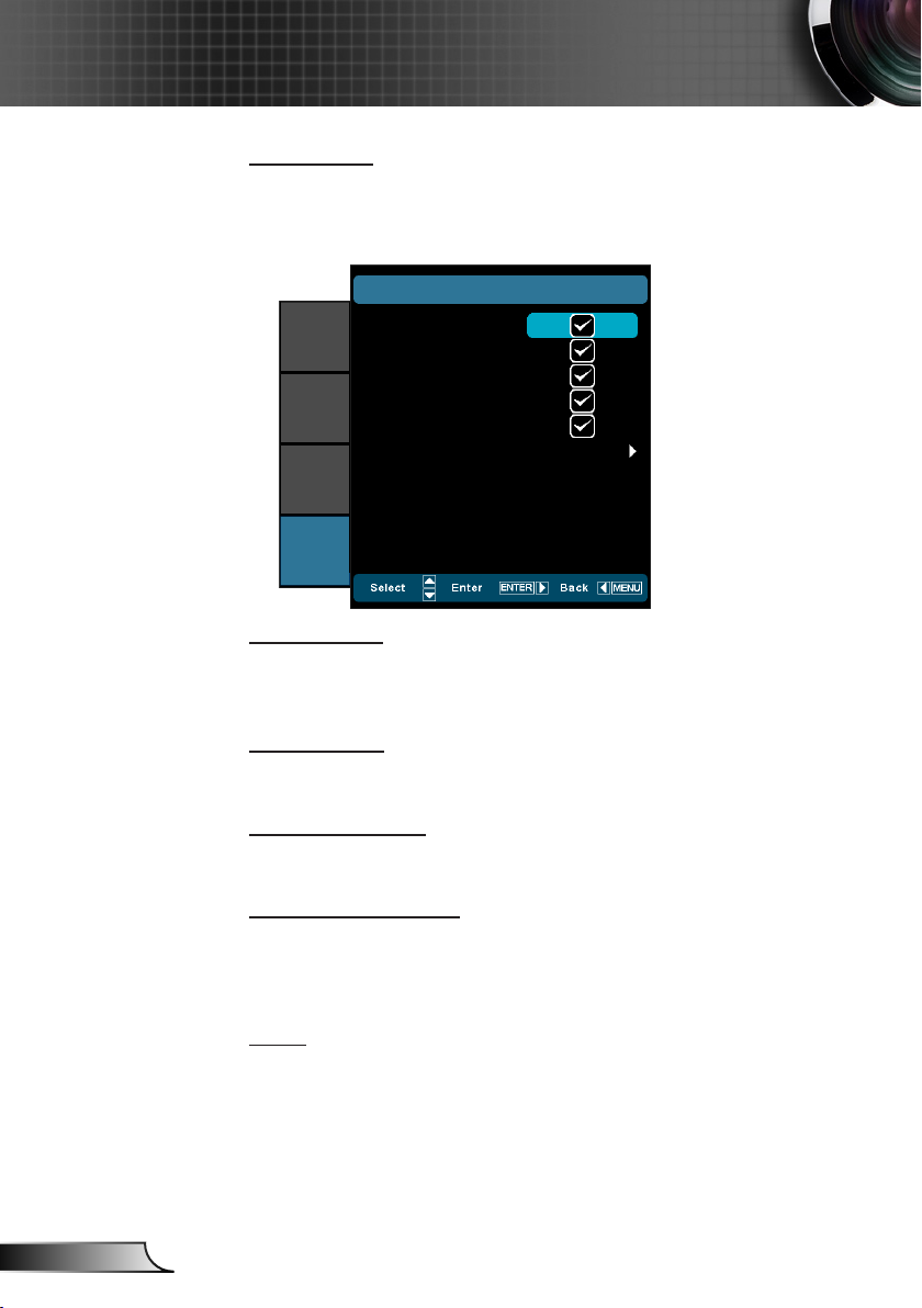
User Controls
Input Source
Use this option to enable / disable input sources. Press ► to enter
the sub menu and select which sources you require. Press “Enter”
to finalize the selection. The projector will only search for inputs
that are enabled.
SETUP |
VGA
IMAGE
DISPLAY
SYSTEM
SETUP
Source Lock
High Altitude
When “On” is selected, the fans will spin faster. This feature is
useful in high altitude areas where the air is thin.
Information Hide
Auto Power Off (min)
Sets the countdown timer interval. The countdown timer will start,
when there is no signal being sent to the projector. The projector
will automatically power off when the countdown has nished (in
minutes).
Reset
Video
HDMI 1
HDMI 2
Component
Exit
On: ` The projector will only search current input connection.
Off: The projector will search for other signals if the current `
input signal is lost.
On: Choose “On” to hide the info message. `
Off: Choose “Off” to show the “searching” message. `
Current: Choose “Yes” to return the display parameters on this `
menu to the factory default settings.
All: Choose “Yes” to return the display parameters on all `
menus to the factory default settings.
INPUT SOURCE
Page 45

45
English
User Controls
SETUP |
HDMI Link Settings
Using HDMI Link
When you connect HDMI CEC-compatible devices to the projector with y
HDMI cables, you can control them on same Power On or Power Off sta-
When HDMI Link
is set to Off, the
standby mode is
<0.5W.
tus using the HDMI Link control feature on the projector’s OSD.
This lets one device or multiple devices in a group Power On or Power Off y
via HDMI Link Feature.
In a typical conguration, your DVD player may be connected to the pro- y
jector through an amplier or home theater system.
SETUP |
HDMI Link Settings
On
Yes
Device -> PJ
Off
IMAGE
DISPLAY
SYSTEM
SETUP
HDMI Link
Inclusive of TV
Power On Link
Power Off Link
Exit
Some HDMI Link
functions may not
operate, depending
on the connected
product’s design
and compliance
with the HDMI CEC
standard.
HDMI
HDMI
Amplier
DVD Player
HDMI Link
Enable/Disable the HDMI Link function. The Inclusive TV, Power
on Link, and Power off Link options will only available if the setting
is set to On.
Inclusive of TV
If the setting is set to “Yes”, both TV and projector will be auto-
matically turned off at the same time. To prevent both devices to
be turned off at the same time, set the setting to “No”.
Power On Link
CEC power on command
Mutual: Both projector and CEC device will be turned on `
simultaneously.
Page 46

46
English
User Controls
PJ -> Device: The CEC device will be turned on only after the `
projector is switched on.
Device -> PJ: The projector will be switched on only after the `
CEC device is turned on.
Power Off Link
If the setting is set to “On”, both HDMI Link and projector will be
automatically turned off at the same time. Set to “Off”, both HDMI
Link and projector will be not automatically turned off at the same
time.
Page 47

47
English
User Controls
SETUP | Signal
(VGA)
SETUP |
SIGNAL
50
0
0
0
Disable
IMAGE
DISPLAY
SYSTEM
Frequency
Phase
H. Position
V. Position
Automatic
Exit
“Signal” is only
supported in Ana-
log VGA (RGB)
signal.
SETUP
Frequency
Change the display data frequency to match the frequency of your
computer’s graphic card. Use this function only if the image appears to icker vertically.
Phase
Synchronize the signal timing of the display with the graphic card.
If the image appears to be unstable or ickers, use this function to
correct it.
H. Position
Press the ◄ to move the image left. `
Press the ► to move the image right. `
V. Position
Press the ◄ to move the image down. `
Press the ► to move the image up. `
Automatic
Automatically congures the signal (the Frequency and Phase
items are grayed out). If Automatic is disabled, the Frequency and
Phase items will appear for user to manually tune and save the
settings.
Page 48

48
English
User Controls
SETUP | Signal
(Video)
IMAGE
DISPLAY
SYSTEM
SETUP |
White Level
Black Level
Saturation
Hue
IRE
Exit
SIGNAL
0
0
0
0
0 IRE
“Signal” is not
supported when
the source is
HDMI.
“IRE” is only sup-
ported on NTSC
signal.
SETUP
White Level
Allow user adjust White Level when inputting Video signals.
Black Level
Allow user adjust Black Level when inputting Video signals.
Saturation
Adjust a video image from black and white to fully saturated color.
Press the ◄ to decrease the amount of color in the image. `
Press the ► to increase the amount of color in the image. `
Hue
Adjust the color balance of red and green.
Press the ◄ to increase the amount of green in the image. `
Press the ► to increase the amount of red in the image. `
IRE
Adjust measurement of composite video signals.
Page 49

49
English
Appendices
Troubleshooting
If you experience a problem with your projector, please refer to
the following information. If a problem persists, please contact
your local reseller or service center.
Image Problems
No image appears on-screen
Ensure all the cables and power connections are correctly and `
securely connected as described in the “Installation” section.
Ensure the pins of connectors are not crooked or broken. `
Make sure you have removed the lens cap and the projector is `
switched on.
Image is out of focus
Make sure the Lens cap is removed. `
Adjust the Focus Ring on the projector lens. `
Make sure the projection screen is between the required dis- `
tance from the projector. (refer to pages 20-21)
The image is stretched when displaying 16:9 DVD title
When you play anamorphic DVD or 16:9 DVD, the projector `
will show the best image in 16: 9 format on projector side.
If you play the LBX format DVD title, please change the format `
as LBX in projector OSD.
If you play 4:3 format DVD title, please change the format as `
4:3 in projector OSD.
If the image is still stretched, you will also need to adjust the `
aspect ratio by referring to the following:
Please setup the display format as 16:9 (wide) aspect ratio `
type on your DVD player.
Image is too small or too large
Adjust the zoom lever on the top of the projector. `
Move the projector closer to or further from the screen. `
Press “Menu” on the projector panel, go to `
“DISPLAY-->Format”. Try the different settings.
Page 50
50
English
Appendices
Image has slanted sides:
If possible, reposition the projector so that it is centered on the `
screen and below the bottom of the screen.
Use “DISPLAY-->V Keystone” from the OSD to make an `
adjustment.
Image is reversed
Select “SYSTEM-->Projection” from the OSD and adjust the `
projection direction.
Blurry double image
Press “3D Format” button and switch to “Auto” to avoid normal `
2D image is blurry double image.
Two images, side-by-side format
Press “3D Format” button and switch to “SBS” for input signal `
is HDMI 1.3 2D 1080i side-by-side.
Image does not display in 3D
Check if the battery of 3D glasses is drained. `
Check if the 3D glasses is turned on. `
When the input signal is HDMI 1.3 2D (1080i side-by-side `
half), press “3D Format” button and switch to “SBS”.
Page 51

51
English
Appendices
Other Problems
The projector stops responding to all controls
If possible, turn off the projector, then unplug the power cord `
and wait at least 20 seconds before reconnecting power.
Remote Control Problems
If the remote control does not work
Check the operating angle of the remote control is within ±25° `
both horizontally and vertically of on of the IR receivers on the
projector.
Make sure there are not any obstructions between the remote `
control and the projector. Move to within 6 m (20 ft) of the
projector.
Make sure batteries are inserted correctly. `
Replace batteries if they are exhausted. `
Page 52

52
English
Appendices
LED Lighting Messages
Power LED on: No
signal; OSD menu
appears and signal
had been detected.
Power LED off:
Signal had been de-
tected but OSD menu
disappears.
Message
Standby State
(Input power cord)
Power on (Warming) Off Flashing Off
Power on and LED lighting Off Steady light Off
Power off (Cooling) Off Flashing Off
Error (LED fail) Flashing Off Off
Error (Fan fail) Flashing Off Flashing
Error (Over Temp.) Flashing Off Steady light
* ON/STANDBY LED be ON when OSD appears, be OFF when OSD disappears.
Power LED
(Red)
Steady light * Off Off
Power LED
(Blue)
Temp LED
(Red)
Page 53

53
English
Appendices
On Screen Messages
Power off:
Power off?
Press power key again
LED warning:
LED Warning
LED Life exceeded.
Temperature warning:
Projector Overheated
The projector will switch off autormatically
Fan failed:
Fan Failure
The projector will switch off autormatically
Out of display range:
Video
Out of range
Page 54

54
English
Appendices
Compatibility Modes
Computer/Video/HDMI/Mac Compatibility
(*1) 1920 x1200
@60Hz only support
RB (reduced blank-
ing).
(*2) 3D timing for
True 3D projector.
(*3) is not supported
HDMI input singal
for Mac.
120Hz input signals
may be dependent
on graphics cards
support.
Signal Resolution
NTSC 720 x 480 60 O - - -
PAL/SECAM 720 x 576 50 O - - -
640 x 480 60 - O O O
VGA
SVGA
XGA
HDTV (720p)
WXGA
SXGA
SXGA+ 1400 x 1050 60 - O O -
UXGA 1600 x1200 60 - O O -
HDTV (1080p)
HDTV (1080i)
WUXGA 1920 x 1200 60
640 x 480 67 - O - -
640 x 480 72.8 - O - O
640 x 480 85 - O - O
800 x 600 56.3 - O - -
800 x 600 60.3 - O O O
800 x 600 72.2 - O O O
800 x 600 85.1 - O O O
800 x 600 120
1024 x 768 60 - O O O
1024 x 768 70.1 - O O O
1024 x 768 75 - O O O
1024 x 768 85 - O O O
1024 x 768 120
1280 x 720 50 O O O -
1280 x 720 60 O O O O
1280 x 720 120
1280 x 768 60 - O O O
1280 x 768 75 - O O O
1280 x 768 85 - O O O
1280 x 800 60 - O O O
1280 x 1024 60 - O O O
1280 x 1024 75 - O O O
1280 x 1024 85 - O O -
1920 x 1080 24 O O O -
1920 x 1080 30 - - O -
1920 x 1080 50 O O O -
1920 x 1080 60 O O O O
1920 x 1080 50 O - O -
1920 x 1080 60 O - O -
Refresh Rate
(Hz)
(*2)
(*2)
(*2)
(*1)
Video Analog HDMI Mac
- O O -
- O O -
- O O -
- O O O
(*3)
(*3)
Page 55

55
English
Appendices
Signal Resolution
SDTV (576i) 720 x 576 50 O - O -
SDTV (576p) 720 x 576 50 O - O -
SDTV (480i) 720 x 480 60 O - O -
SDTV (480p) 720 x 480 60 O - O -
Refresh Rate
(Hz)
Video Analog HDMI Mac
3D Input Video Compatibility
Input Timing
1280 x 720p @ 50Hz Top-and-Bottom
1280 x 720p @ 60Hz Top-and-Bottom
HDMI 1.4a 3D
Input
Input
Resolution
HDMI 1.3 3D
Content
1280 x 720p @ 50Hz Frame packing
1280 x 720p @ 60Hz Frame packing
1920 x 1080i @ 50 Hz Side-by-Side (Half)
1920 x 1080i @ 60 Hz Side-by-Side (Half)
1920 x 1080p @ 24 Hz Top-and-Bottom
1920 x 1080p @ 24 Hz Frame packing
1920 x 1080p @ 60Hz
1920 x 1080i @ 50Hz
1920 x 1080i @ 60Hz
1280 x 720p @ 50Hz
1280 x 720p @ 60Hz
1920 x 1080p @ 60Hz
1920 x 1080i @ 50Hz
1920 x 1080i @ 60Hz
1280 x 720p @ 50Hz
1280 x 720p @ 60Hz
480i HQFS
Side-by-Side (Half)
Top-and-Bottom
While 3D Format is
While 3D Format is
“Top and Bottom”
While 3D Format is
“Frame Sequential”
“SBS”
Page 56

56
English
Appendices
12345
6789
RS232 Commands and Protocol
Function List
RS232 Pin Assignments
Pin no.
1 N/A
2 RXD
3 TXD
4 N/A
5 GND
6 N/A
7 N/A
8 N/A
9 N/A
Spec.
(from projector side)
Page 57

57
English
Appendices
Optoma Data and HT Projectors HD91/HD90
Baud Rate 9600
Data Bits 8
Parity None
Stop Bits 1
Flow Control None
UART16550 FIFO Disable
~ X X X X X n CR
space variable carriage return
ASCII Pass Fail
Power On/Off n=1/n=0 & 2 ~XX00 n P F
Re-sync ~XX01 n P F
HDMI 1 n=1
~XX12 n P
VGA n=5
VGA Com
p
onent n=8
Video
n=10
Com
p
onent RCA
n=14
HDMI 2
n=15
Cinema n=1
~XX20 n P F
Film n=11
Bright n=2
Photo n=3
Reference n=4
User n=5
ISF Day n=7
ISF Night n=8
3D n=9
Brightness n= -50 - +50 ~XX21 n P F
Contrast n= -50 - +50 ~XX22 n P F
Sharpness n= 0 - +15 ~XX23 n P F
Tint n= -50 - +50 ~XX44 n P F
Color n= -50 - +50 ~XX45 n P F
Red Gain
n= -50 - +50
~XX24 n
Green Gain n= -50 - +50 ~XX25 n
Blue Gain n= -50 - +50 ~XX26 n
Red Bias n= -50 - +50 ~XX27 n
Green Bias n= -50 - +50 ~XX28 n
Blue Bias n= -50 - +50 ~XX29 n
Reset n=1 ~XX33 n
D50 n=1 ~XX210 n
D65 n=2 ~XX210 n
D75 n=4 ~XX210 n
D83 n=5 ~XX210 n
D93 n=6 ~XX210 n
Native n=7 ~XX210 n
Native n=1 ~XX211 n
Adobe n=6 ~XX211 n
DLP Cinema n=2 ~XX211 n
HDTV n=3 ~XX211 n
SMPT-C n=5 ~XX211 n
Red n=1 ~XX212 n
Green n=2 ~XX212 n
Blue n=3 ~XX212 n
Cyan n=4 ~XX212 n
Yellow n=5 ~XX212 n
Magenta n=6 ~XX212 n
x offset -50 ~ 50 n= -50 - +50 ~XX213 n
y offset -50 ~ 50 n= -50 - +50 ~XX214 n
Brightness -50 ~ 50 n= -50 - +50 ~XX217 n
Reset n=1 ~XX215 n
Film
n=1
~XX35 n P F
Curve Type
Film/Video/Graphics/1.8
/1.9/2.0/2.1/2.2/2.3/2.4/2.5/2.6
n=-5 - +6
~XX182 n
Offset
n=-5 - +5
~XX183 n
Reset n=1 ~XX206 n
Video
n=2
~XX35 n
Curve Type
Film/Video/Graphics/1.8
/1.9/2.0/2.1/2.2/2.3/2.4/2.5/2.6
n=-5 - +6
~XX184 n
Offset
n=-5 - +5
~XX185 n
Reset n=1 ~XX207 n
Graphics
n=3
~XX35 n
Curve Type
Film/Video/Graphics/1.8
/1.9/2.0/2.1/2.2/2.3/2.4/2.5/2.6
n=-5 - +6
~XX186 n
Offset
n=-5 - +5
~XX187 n
Reset n=1 ~XX208 n
Standard
n=4
~XX35 n
Curve Type
Film/Video/Graphics/1.8
/1.9/2.0/2.1/2.2/2.3/2.4/2.5/2.6
n=-5 - +6
~XX188 n
Offset
n=-5 - +5
~XX189 n
Reset n=1 ~XX209 n
Auto n=1
~XX37 n P F
RGB (0-255)* * RGB (0-255) supports when HDMI is detected n=2
RGB(16 - 235)* *RGB(16 - 235)supports when HDMI is detected n=4
YUV n=3
Noise Reduction
n= 0 - 10
~XX196 n P F
PureMotion
OFF
n=0
~XX190 n
LOW
n=1
~XX190 n
MED
n=2
~XX190 n
HIGH n=3 ~XX190 n
UltraDetai
l
OFF
n=0
~XX41 n
ON
n=1
~XX41 n
HD+
n=2
~XX41 n
PureColor
OFF
n=0
~XX42 n
1
n=1
~XX42 n
2
n=2
~XX42 n
3
n=3 ~XX42 n
4
n=4
~XX42 n
5
n=5
~XX42 n
PureEn
g
ine Demo
OFF
n=0
~XX197 n
H Split
n=1
PF
V Split
n=2
PF
Power
100%/95%/90%/85%/
80%/75%/70%/65%/
60%/50%
n=0/n=1/n=2/n=3/n=4
/n=5/n=6/n=7/n=8/n=9
~XX326 n P
F
DynamicBlack 1 n=1 P F
DynamicBlack 2 n=2 P F
DynamicBlack 3 n=3 P F
4:3
n=1
~XX60 n P F
16:9 n=2
LBX n=5
Native n=6
Auto235 n=8
Auto235_Subtitle n=11
SuperWide n=9
Edge masking n=0-5 ~XX61 n P F
~XX191 n
DISPLAY
Don't support when Anamorphic lens is fixed
Don't support when Anamorphic lens is motored or fixed
LED Brightness
Supportingit When Anamorphic lens is fixed or motor
Don't support when Anamorphic lens is motored or fixed
Projector ID Command ID
Function
Direct Source Commands
Color Space
Advanced
Color Gamut
PureEngine
CMS
Gamma
IMAGE
RGB Gain/Bias
Color Temperature
Display Mode
Format
Color Settings
RS232 Protocol Function List
Baud Rate : 9600
Data Bits: 8
Parity: None
Stop Bits: 1
Flow Control : None
UART16550 FIFO: Disable
Projector Return (Pass): P
Projector Return (Fail): F
XX=00-99, projector's ID,
XX=00 is for all projectors
There is a <CR> after all ASCII commands.
0D is the HEX code for <CR> in ASCII code.
Page 58

58
English
Appendices
R CnXXXXX~
space variable carriage returnProjector ID Command ID
Zoom FPn 2 6XX~0 1 - 0 = n
H Image Shift FPn 3 6XX~0 0 1 + - 0 0 1 - = n
V Image Shift FPn 4 6XX~0 0 1 + - 0 0 1 - = n
V Keystone FPn 6 6XX~03+ - 03- =n
3D->2D 3D / L / R
2D->2D; 3D->3D / 3D->L /3D->R
n=1/n=2/n=3
FPn 0 0 4 X X ~
Auto
n=0
FPn 5 0 4 X X ~
FP1 = nS B S
FP2 = nmo t t oB dn a p oT
FP3 = nl a i t n e u q e S e m a r F
Low FP4 = n
Mid FP5 = n
Hig
h
n=6
FP
n 1 3 2 X X ~1 = n / 0 = nf f O / n Ot r e v n I . c n y S D 3
Top Left n=1
FPn 2 7XX~
Top Right n=2
Centre n=3
Bottom Left n=4
Bottom Right n=5
LED Hours n=1 ~XX108 n Oknnnnn return LED hour
Front-Desktop n=1
FPn 1 7XX~
Rear-Desktop n=2
Front-Ceiling n=3
Rear-Ceiling n=4
Test Pattern
None / Grid / White Patter
n
n=0/n=1/n=2
~XX195 n
Blue n=1
FPn 4 0 1 X X ~
Black n=2
Gray n=6
IR Function
A
ll/Front/Top
n=0 /n=1 / n=2
FPn 1 1XX~
12V Trigger A
Off\On
n=0/n=1
~XX192 n
12V Trigger B
Off/On/Auto235/Auto 3D
n=0/n=1/n=2/n=3
~XX193 n
4:3 4:3 check ~XX205 0
4:3 unchec
k
~XX205 1
16:9 16:9 check ~XX205 2
16:9 uncheck ~XX205 3
Letter Box letter box check ~XX205 4
letter box unchec
k
~XX205 5
Nativ
e
native chec
k
~XX205 6
native unchec
k
~XX205 7
Exi
t
English
n=1
FPn 0 7XX~
German n=2
French n=3
Italian n=4
Spanish n=5
Portuguese n=6
Polish n=7
Dutch n=8
Swedish n=9
Norwegian/Danish n=10
Finnish n=11
Greek n=12
Traditional Chinese n=13
Simplified Chinese n=14
Japanese n=15
Korean n=16
Russian n=17
Hungarian n=18
Czech n=19
Arabic n=20
Thai
n=21
Turkish
n=22
HDMI 1 n=1
FPn 9 3XX~
HDMI 2 n=7
VGA n=5
3 x RCA Comnponent
n=8
Video
n=10
Source Lock
On/Off
n=1/n=0 & 2
FPn 0 0 1 X X ~
f f O / n Oe d u t i t l A h g i H FPn 1 0 1 X X ~2 & 0 = n / 1 = n
Information Hide
On/Off
n=1/n=0 & 2
FPn 2 0 1 X X ~
Auto Power Off (min) FPn 6 0 1 X X ~0 8 1 - 0 = n
Automatic
Enable/Disable
n=1/n=0
~XX91 n
Frequency\Tracking FPn 3 7XX~0 0 1 ~ 0 = n
Phase FPn 4 7XX~05+ - 05- =n
H. Position FPn 5 7XX~05+ - 05- =n
V. Position FPn 67XX~05+ - 05- =n
White level
n=-50-+50 ~XX200 n
Black level
n=-50-+50 ~XX201 n
Saturation
-50~+50
~XX202 n
Hue
-50~+50
~XX203 n
IRE
0 IRE / 7.5 IRE
n=1/n=0
~XX204 n
Yes
n=1
FPn 2 1 1 X X ~
No n=2
Information from Projector Automatically
when: Standby Mode a O F N I0 = a
Warming up a O F N I1 = a
Cooling Down a O F N I2 = a
Out of Range a O F N I3 = a
LED Fail a=4
Thermal Switch Error a=5
Fan Lock a=6
Over Temperature a=7
Lamp Hours Running Out a=8
READ/Return Information from projector
Information n=1 ~XX150 n Okabbbbbccddddee
n O \ f f Oe t a t S r ewo P = a a=0/1
b = LED Hour bbbbb
c = Input Source Commands None c=00
VGA c=02
Video c=05
HDMI1 c=07
HDMI2 c=08
d = Firmware Version dddd
e n o Nedom y a l ps i D = e ee=0
Cinema ee=1
Bright ee=2
Film ee=11
Photo ee=3
Reference
ee=4
User ee=5
ISF Day ee=7
ISF Night ee=8
3D ee=9
Model Name ~XX151 n Oka
Depends a=0/1/2
Language
Projection
When Movable lens is selected,
12V Trigger B won't accept any
commands )
DISPLAY
Background Color
3D Format
Decoding HDMI1.3
3D timing
2D->3D
SYSTEMSETUP
Menu Location
Signal
Input Source FIlters
Reset
3D
Page 59

59
English
Appendices
~ X X X X X n CR
space variable carriage returnProjector ID Command ID
RS232 Version No n=1 ~XX152 n Oka
Depends a=???
Input Source Commands
None/VGA/Video/HDMI1/
HDMI2/Component
n=1
~XX121 n
Oka a=0/2//5//7/8/11
Software Version n=1 ~XX122 n Okdddd
Display Mode
None/Cinema/Bright/Photo/
Reference/User/ISF Day/
ISF Night/3D/Film
n=1
~XX123 n
Oka a=0/1/2/3/4/5/7/8/9/11
Power State On/Off n=1 ~XX124 n Oka a=1/0
Brightness n=1 ~XX125 n Oka
Contras
t
n=1
~XX126 n
Ok
a
Aspect Ratio
4:3/16:9/LBX/Native/Auto235/
Auto235_Subtitle
n=1
~XX127 n
Oka
aa=1/2/5/6/8//9/11
for 4:3/16:9/LBX/
Native/Auto235/
A
uto235 Subtitle
Color Temperature
D50/D65/D70/D75/D83/D93/
Nativ
e
n=1
~XX128 n
Oka a=1/2 /3/4/5/6/7
Projection Mode
Front-Desktop Rear-Desktop
Front-Ceiling Rear-Ceiling
n=1 ~XX129 n Oka
a=0/1/2/3 for Front-
Desktop/Rear-Desktop
/Front-Ceiling/Rear-
Ceilin
g
Remote Control
Up n=10 ~XX140 n
Left n=11
Enter n=12
Right n=13
Down n=14
Menu n=20
Re-sync n=41
Page 60

60
English
Appendices
138.5
138.5
151.50
110.00
110.00
148.5
66.0
172.1
12.9
24.5
442.3
344.2
Ceiling Mount Installation
To prevent damage to your projector, please use the Optoma 1.
ceiling mount.
If you wish to use a third party ceiling mount kit, please ensure 2.
the screws used to attach a mount to the projector meet the fol-
lowing specications:
Please note that
damage resulting from
incorrect installation
will void the warranty.
Lens
Warning:
1. If you buy a ceiling mount from another company, please be sure to use the correct
screw size. Screw size will vary depending on the thickness of the mounting plate.
2. Be sure to keep at least 10 cm gap between the ceiling and the bottom of the projector.
3. Avoid installing the projector near a heat source.
Screw type: M6 `
Maximum screw length: 12mm `
Minimum screw length: 10mm `
Unit: mm
Page 61
61
English
Appendices
Optoma Global Ofces
For service or support please contact your local ofce.
USA
3178 Laurelview Ct.
Fremont, CA 94538, USA
www.optomausa.com
Canada
3178 Laurelview Ct.
Fremont, CA 94538, USA
www.optomausa.com
Latin America
3178 Laurelview Ct.
Fremont, CA 94538, USA
www.optomausa.com
Europe
42 Caxton Way, The Watford Business Park Watford, Hertfordshire,
WD18 8QZ, UK
www.optoma.eu
Service Tel: +44 (0)1923 691865
888-289-6786
510-897-8601
services@optoma.com
888-289-6786
510-897-8601
services@optoma.com
888-289-6786
510-897-8601
services@optoma.com
+44 (0) 1923 691 800
+44 (0) 1923 691 888
service@tsc-europe.com
Benelux BV
Randstad 22-123
1316 BW Almere
The Netherlands
www.optoma.nl
France
Bâtiment E
81-83 avenue Edouard Vaillant
92100 Boulogne Billancourt, France
Spain
C/ José Hierro,36 Of. 1C 28522
Rivas VaciaMadrid,
Spain
+31 (0) 36 820 0253
+31 (0) 36 548 9052
+33 1 41 46 12 20
+33 1 41 46 94 35
savoptoma@optoma.fr
+34 91 499 06 06
+34 91 670 08 32
Page 62
62
English
Appendices
Deutschland
Wiesenstrasse 21 W
D40549 Düsseldorf,
Germany
Scandinavia
Lerpeveien 25
3040 Drammen
Norway
PO.BOX 9515
3038 Drammen
Norway
Korea
WOOMI TECH.CO.,LTD.
4F, Minu Bldg. 33-14, Kangnam-Ku,
seoul,135-815, KOREA
Japan
東京都足立区綾瀬3-25-18
株式会社オーエスエム
サポートセンター: 0120-46-5040
Taiwan
12F., No.215, Sec. 3, Beixin Rd.,
Xindian Dist., New Taipei City 231,
Taiwan, R.O.C.
www.optoma.com.tw
+49 (0) 211 506 6670
+49 (0) 211 506 66799
info@optoma.de
+47 32 98 89 90
+47 32 98 89 99
info@optoma.no
+82+2+34430004
+82+2+34430005
info@osscreen.com
www.os-worldwide.com
+886-2-8911-8600
+886-2-8911-6550
services@optoma.com.tw
asia.optoma.com
Hong Kong
Unit A, 27/F Dragon Centre,
79 Wing Hong Street,
Cheung Sha Wan,
Kowloon, Hong Kong
China
5F, No. 1205, Kaixuan Rd.,
Changning District
Shanghai, 200052, China
+852-2396-8968
+852-2370-1222
www.optoma.com.hk
+86-21-62947376
+86-21-62947375
www.optoma.com.cn
Page 63

63
English
Appendices
Regulation & Safety Notices
This appendix lists the general notices of your projector.
FCC Notice
This device has been tested and found to comply with the limits for a Class B
digital device pursuant to Part 15 of the FCC rules. These limits are designed
to provide reasonable protection against harmful interference in a residential
installation. This device generates, uses and can radiate radio frequency
energy and, if not installed and used in accordance with the instructions, may
cause harmful interference to radio communications.
However, there is no guarantee that interference will not occur in a particular
installation. If this device does cause harmful interference to radio or television
reception, which can be determined by turning the device off and on, the user
is encouraged to try to correct the interference by one or more of the following
measures:
Reorient or relocate the receiving antenna.
Increase the separation between the device and receiver.
Connect the device into an outlet on a circuit different from that to which
the receiver is connected.
Consult the dealer or an experienced radio/television technician for help.
Notice: Shielded cables
All connections to other computing devices must be made using shielded
cables to maintain compliance with FCC regulations.
Caution
Changes or modications not expressly approved by the manufacturer could
void the user’s authority, which is granted by the Federal Communications
Commission, to operate this projector.
Operation Conditions
This device complies with Part 15 of the FCC Rules. Operation is subject to
the following two conditions:
This device may not cause harmful interference and1.
This device must accept any interference received, including interference 2.
that may cause undesired operation.
Notice: Canadian users
This Class B digital apparatus complies with Canadian ICES-003.
Remarque à l’intention des utilisateurs canadiens
Cet appareil numerique de la classe B est conforme a la norme NMB-003 du
Canada.
Page 64

64
English
Appendices
Declaration of Conformity for EU countries
EMC Directive 2004/108/EC (including amendments) y
Low Voltage Directive 2006/95/EC y
R & TTE Directive 1999/5/EC (if product has RF function) y
Disposal instructions
Do not throw this electronic device into the trash when
discarding. To minimize pollution and ensure utmost
protection of the global environment, please recycle it.
Page 65

65
English
Appendices
Trademarks
DLP is trademarks of Texas Instruments.•
IBM is a trademark or registered trademark of International •
Business Machines Corporation.
Macintosh, Mac OS X, iMac, and PowerBook are trade-•
marks of Apple Inc., registered in the U.S. and other
countries.
Microsoft, Windows, Windows Vista, Internet Explorer and •
PowerPoint are either a registered trademark or trademark
of Microsoft Corporation in the United States and/or other
countries.
HDMI, the HDMI Logo and High-Denition Multimedia •
Interface are trademarks or registered trademarks of HDMI
Licensing LLC.
Other product and company names mentioned in this •
user’s manual may be the trademarks or registered trade-
marks of their respective holders.
 Loading...