

Page 1

Table of contents
Table of Contents ...................................................................................1
Usage Notice
Safety Information .........................................................................................3
Precautions....................................................................................................4
Eye Safety Warnings
Introduction.............................................................................................7
Package Overview.........................................................................................7
Product Overview
Main Unit ................................................................................................................8
Connection Ports
Remote Control
Backup Remote Control
Coin Cell Battery Replacement
Installation ............................................................................................12
Connecting the Projector .............................................................................12
Connect to Notebook/DVI/VGA-In .......................................................................12
Connecting the Projector .............................................................................13
Connect to Video Sources ...................................................................................13
Installing or Removing the Optional Lens ....................................................14
Removing the Existing Lens From the Projector ..................................................14
Installing the New Lens
Powering On/Off the Projector.....................................................................16
Powering On the Projector ...................................................................................16
Powering
Warning Indicator
Adjusting the Projected Image.....................................................................18
Adjusting the Projector’s Height ...........................................................................18
Adjusting Projected Image Position Using PureShift
Adjusting Projection Image Size
User Controls .......................................................................................23
Remote Control ...........................................................................................23
On-screen Display Menus
How to operate ....................................................................................................25
Menu Tree ...................................................................................................26
Image ...................................................................................................................27
Image | Advanced
Image | Advanced | PureEngine
Display
System
System | Lamp Settings
System | Startup Image
Setup
..........................................................................................3
.....................................................................................6
..........................................................................................8
...................................................................................................9
....................................................................................................10
....................................................................................... 11
............................................................................ 11
........................................................................................15
Off the Projector ...................................................................................17
.................................................................................................17
...........................................19
..........................................................................21
...........................................................................25
................................................................................................29
..........................................................................31
.................................................................................................................32
.................................................................................................................35
....................................................................................... 38
.......................................................................................39
....................................................................................................................40
English
1
Page 2

Table of contents
Appendicess .........................................................................................43
Troubleshooting ...........................................................................................43
Image Problems ...................................................................................................43
Other Problems
Projector Status Indication
Remote Control Problems
Replacing the Lamp.....................................................................................48
Compatibility Modes
RS232 Commands and Protocol Function List............................................52
RS232 Pin Assignments ......................................................................................52
RS232 Protocol Function List
Ceiling Mount Installation ............................................................................56
Optoma Global Ofces
Regulation & Safety Notices
....................................................................................................44
...................................................................................45
....................................................................................47
....................................................................................51
..............................................................................53
................................................................................57
........................................................................59
2
Page 3
Usage Notice
Safety Information
The lightning ash with arrow head within an equilateral triangle is
intended to alert the user to the presence of uninsulated “dangerous
voltage” within the product’s enclosure that may be of sufcient
magnitude to constitute a risk of electric shock to persons.
The exclamation point within an equilateral triangle is intended to alert
the user to the presence of important operating and maintenance
(servicing) instructions in the literature accompanying the appliance.
WARNING: TO REDUCE THE RISK OF FIRE OR ELECTRIC SHOCK, DO NOT
EXPOSE THIS APPLIANCE TO RAIN OR MOISTURE. DANGEROUS HIGH
VOLTAGES ARE PRESENT INSIDE THE ENCLOSURE. DO NOT OPEN THE
CABINET. REFER SERVICING TO QUALIFIED PERSONNEL ONLY.
Class B emissions limits
This Class B digital apparatus meets all requirements of the Canadian
Interference-Causing Equipment Regulations.
Important Safety Instruction
1. Do not block any ventilation openings. To ensure reliable operation of
the projector and to protect from over heating, it is recommended to
install the projector in a location that does not block ventilation. As an
example, do not place the projector on a crowded coffee table, sofa,
bed, etc. Do not put the projector in an enclosure such as a book case
or a cabinet that restricts air ow.
2. Do not use the projector near water or moisture. To reduce the risk of
re and/or electric shock, do not expose the projector to rain or
moisture.
3. Do not install near heat sources such as radiators, heaters, stoves or
any other apparatus such as ampliers that emits heat.
4. Clean only with dry cloth.
5. Only use attachments/accessories specied by the manufacturer.
6. Do not use the unit if it has been physically damaged or abused.
Physical damage/abuse would be (but not limited to):
▀■ Unit has been dropped.
▀
■ Power supply cord or plug has been damaged.
■ Liquid has been spilled on to the projector.
▀
▀■ Projector has been exposed to rain or moisture.
▀
■ Something has fallen in the projector or something is loose inside.
Do not attempt to service the unit yourself. Opening or removing covers
may expose you to dangerous voltages or other hazards. Please call
Optoma before you send the unit for repair.
7. Do not let objects or liquids enter the projector. They may touch
dangerous voltage points and short out parts that could result in re or
electric shock.
8. See projector enclosure for safety related markings.
9. The unit should only be repaired by appropriate service personnel.
English
3
Page 4

Usage Notice
Note
Note
Precautions
Please follow all warnings, precautions and
maintenance as recommended in this user’s
guide.
▀■ Warning-
▀■ Warning-
▀■ Warning-
▀■ Warning-
▀■ Warning-
▀■ Warning-
▀■ Warning-
When the lamp reaches
the end of its life, the
projector will not turn
back on until the lamp
module has been
replaced. To replace
the lamp, follow the
procedures listed under
“Replacing the Lamp”
section on page 45.
▀■ Warning-
▀■ Warning-
Do not look into the projector’s lens when the
lamp is on. The bright light may hurt your
eyes.
To reduce the risk of re or electric shock, do
not expose this projector to rain or moisture.
Please do not open or disassemble the
projector as this may cause electric shock.
When replacing the lamp, please allow the
unit to cool down. Follow instructions as
described on page 48.
This projector will detect the life of the lamp
itself. Please be sure to change the lamp
when it shows warning messages.
Reset the “Lamp Reset” function from the
on-screen display “System|Lamp Setting”
menu after replacing the lamp module
(refer to page 38).
When switching the projector off, please
ensure the cooling cycle has been completed
before disconnecting power. Allow 90 seconds
for the projector to cool down.
Do not use lens cap when projector is in
operation.
When the lamp is approaching to the end of its
life time, the message “Replacement
suggested” will show on the screen.
Please contact your local reseller or service
center to change the lamp as soon as
possible.
4
Page 5
Usage Notice
Do:
▀■ Turn off and unplug the power plug from the AC outlet before
cleaning the product.
Use a soft dry cloth with mild detergent to clean the display
▀■
housing.
Disconnect the power plug from AC outlet if the product is not
▀■
being used for a long period of time.
Do not:
▀■ Block the slots and openings on the unit provided for
ventilation.
▀■ Use abrasive cleaners, waxes or solvents to clean the unit.
▀■ Use under the following conditions:
- In extremely hot, cold or humid environments.
Ensure that the ambient room temperature is
within 5 - 35°C
Relative Humidity is 5 - 35°C, 80% (Max.), non-condensing
- In areas susceptible to excessive dust and dirt.
Near any appliance generating a strong magnetic eld.
-
In direct sunlight.
-
English
5
Page 6

Usage Notice
Eye Safety Warnings
▀■ Avoid staring/facing directly into the projector beam at all
times. Keep your back to the beam as much as possible.
▀■ When projector is used in a classroom, adequately supervise
students when they are asked to point out something on the
screen.
▀■ In order to minimize the lamp power, use room blinds to
reduce ambient light levels.
6
Page 7
Introduction
Note
Note
CR2025
3V
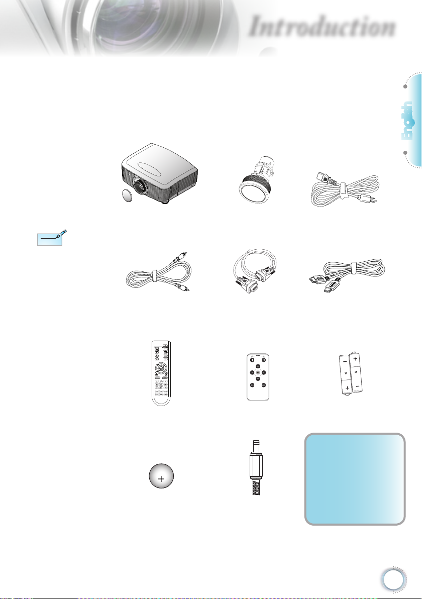
Package Overview
Unpack and inspect the box contents to ensure all
parts listed below are in the box. If something is
missing, please contact Optoma customer service.
English
Due to different
applications in each
Country, some regions
may have different
accessories.
Projector with lens cap
Composite Video Cable
(Not Available in European Version)
Backup Remote Battery 12V Trigger Connector
1.8m
Remote Control Backup Remote Control
Option lens
(Standard lens, Long throw lens,
Short throw lens)
RS232 Cable 2.0m HDMI Cable 1.8m
(EMEA/USA*2, ASIA*1)
Power Cord 1.8m
(Europe Only)
2 x AA Batteries
Documentation :
User’s Manual
Warranty Card
Quick Start Card
WEEE Card
7
Page 8
Introduction
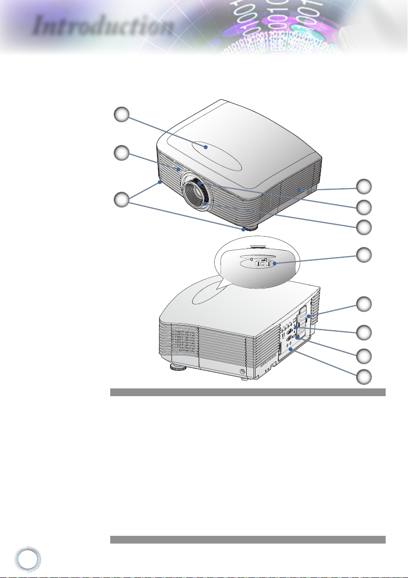
Product Overview
Main Unit
1
2
3
4
5
6
7
8
9
10
11
1. Lens Shift Adjustment Cover
2. IR Receiver
3. Tilt-Adjustment Feet
4. Lamp Replacement Cover
5. Zoom
6. Focus
7. Vertical and Horizontal Lens Shift Adjustment Control and
Lens Release
8. Backup Remote Tray
9. LED Indicators
10. Power Button
11. Connection Ports
8
Page 9
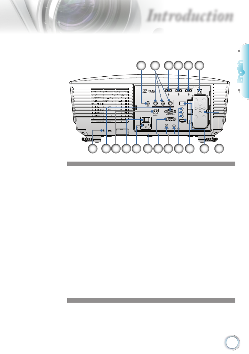
Connection Ports
Introduction
3 4 5 621
English
1. Composite Video
2. Component Video
3. HDMI 1
4. HDMI 2
5. HDMI 3
6. Service connector (USB B-TYPE )
7. Backup Remote Tray
8. IR Receiver
9. Power Button
10. LED Indicators
11. 12V OUT B
12. 12V OUT A
13. RS232
14. Power Socket
15. Main Power Switch
16. S-Video
17. VGA Input
18. Kensington MicrosaverTM Lock Port
10111218 13141617 15
79 8
9
Page 10
Introduction
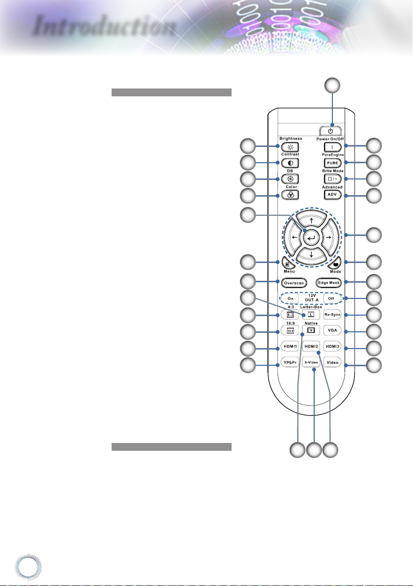
Remote Control
1. Power On
2. Power Off
3. PureEngine
4. Brite Mode
5. Advanced
6. Four Directional Select
Keys
7. Mode
8. Edge Mask
9. 12V OUT A On/Off
10. Re-Sync
11. VGA
12. HDMI 3
13. Video
14. HDMI 2
15. S-Video
16. Native
17. YPbPr
18. HDMI 1
19. 16:9
20. 4:3
21. Letter-Box
22. Overscan
23. Menu
24. Enter
25. Color
26. DynamicBlack
27. Contrast
28. Brightness
28
27
26
25
24
23
22
21
20
19
18
17
1
2
3
4
5
6
7
8
9
10
11
12
13
15 1416
10
Page 11
Introduction
Note
Note
3
V
O
L
T
S
CR2025
M
n
O
2
-
L
i
C
E
L
L
3
V
O
L
T
S
J
A
P
A
N
H
CR2025
3
V
O
L
T
S
CR2025
M
3
V
O
L
T
S
CR2025
Note
Note
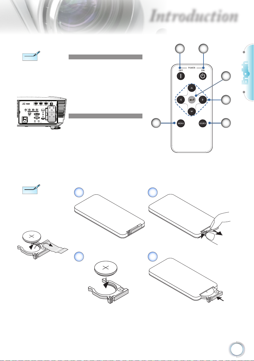
Backup remote
control is
magnetically attached
to the back I/O of the
projector.
Before using the
remote control for the
rst time, remove the
transparent insulation
tape.
Backup Remote Control
1. Power Off
2. Power On
3. Enter
4. Four Directional Select
Keys
5. Source
6. Menu
6
Coin Cell Battery Replacement
1 2
1
2
3
English
4
5
3 4
11
Page 12
Installation
Note
Note
E62405SP
R
VGA,DVI
VGA,DVI
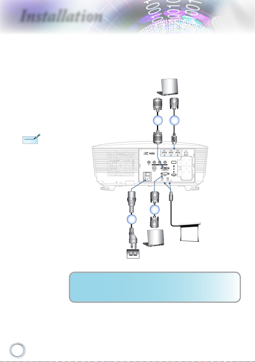
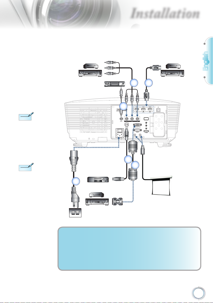
Connecting the Projector
Connect to Notebook/DVI/VGA-In
Due to the difference
in applications for each
country, some regions
may have different
accessories.
1 2
12
4
3
1.................................................................... VGA Input Cable (Europe Only)
2..........................................................DVI/HDMI Cable (Optional Accessory)
3....................................................................................................Power Cord
4...............................................................RS232 Cable (Optional Accessory)
Page 13
Due to the difference
Note
Note
DVD player, Set-top Box
HDTV receiver
Video Output
S-Video Output
DVD player, Set-top Box
HDTV receiver
DVD player, Set-top Box
HDTV receiver
E62405SP
R
Note
Note
in applications for each
country, some regions
may have different
accessories.
Installation
Connecting the Projector
Connect to Video Sources
2 3
1
English
12V OUT is a
programmable trigger.
5
6
4
1.......................Composite Video Cable (Not Available in European Version)
2...............................RCA Component Cable for YPbPr (Optional Accessory)
3............................................................................HDMI Cable (Europe Only)
4....................................................................................................Power Cord
5.............................................................S-Video Cable (Optional Accessory)
6...............................................SCART RGB/S-Video Adapter (Europe Only)
13
Page 14
Installation
Installing or Removing the Optional Lens
Caution
• Do not shake or place excessive pressure on the
projector or the lens components as the projector and
lens components contain precision parts.
• Before removing or installing the lens, be sure to turn off
the projector, wait until the cooling fans stop, and turn
off the main power switch.
• Do not touch the lens surface when removing or
installing the lens.
• Keep ngerprints, dust or oil off the lens surface.
Do not scratch the lens surface.
• Work on a level surface with a soft cloth under it to avoid
scratching.
• If you remove and store the lens, attach the lens cap to
the projector to keep off dust and dirt.
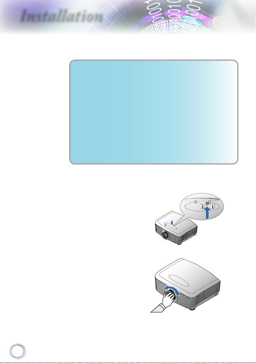
Removing the Existing Lens From the Projector
14
1. Push down and
release the top cover
to open.
2. Push the LENSE
RELEASE button to
the unlock
position.
3. Grasp the lens.
4. Rotate the lens
counterclockwise.
The existing lens will
be disengaged.
Page 15
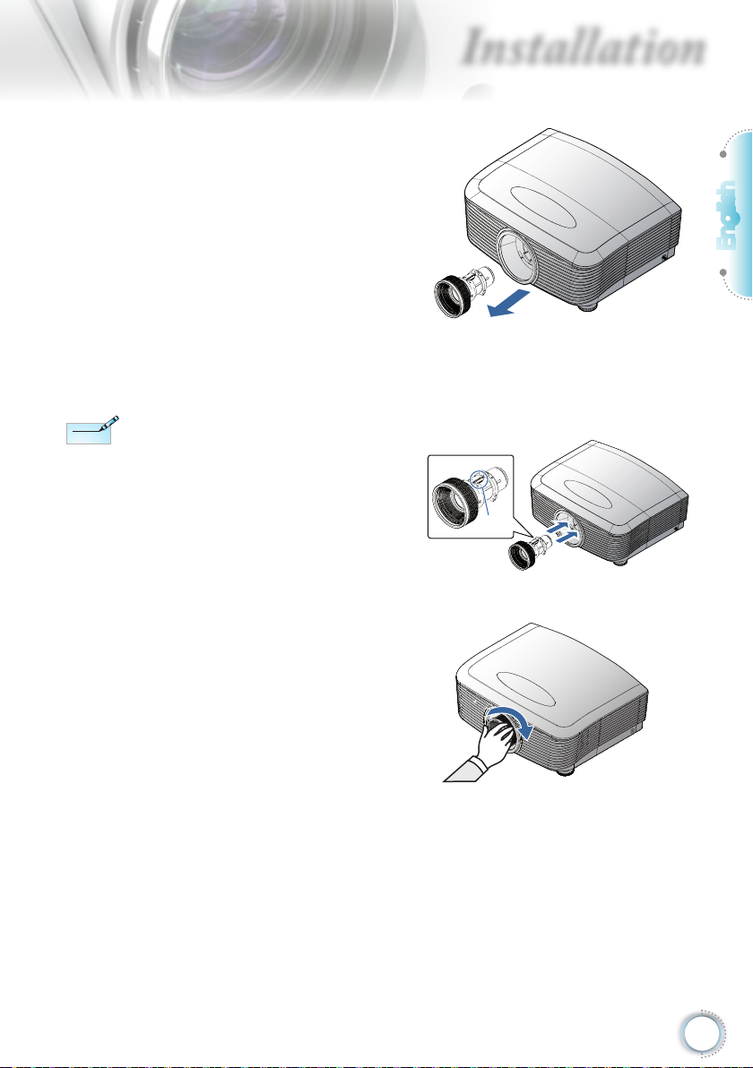
Pin of IRIS should be in
Note
Note
the direction as shown
in the picture.
3. Pull out the existing
lens slowly.
Installing the New Lens
1. Align the notches and
correctly position
the electrical contact
pad as shown in the
picture.
Installation
Pin of
IRIS
English
2. Rotate the lens
clockwise until you
feel it click into place.
15
Page 16
Installation
Note
Note
Powering On/Off the Projector
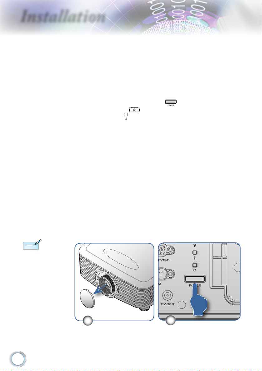
Powering On the Projector
1. Remove the lens cap.
2. Securely connect the power cord and signal cable. When
connected, the power led will turn red.
3. Turn on the lamp by pressing “
the projector or “
The power led “ ” will now ash blue.
The startup screen will display in approximately 30 seconds.
The rst time you use the projector, you can select your
preferred language from quick menu after the startup screen
display.
4. Turn on your source that you want to display on the screen
(computer, notebook, video player, etc). The projector will
detect the source automatically and will display on the
screen. If not, push menu button and go to “SETUP”. Make
sure that the “Source Lock” has been set to “Off”.
” button on the rear of
” on the remote control.
Turn on the projector
rst and then select the
signal sources.
First time to turn on the
projector:
Remember to select the
type of lens you have
installed. Detail see
page 37
16
▀■If you connected multiple sources at the same time, press
the “Source” key on the remote control to switch between
inputs.
1
2
Page 17
Installation
Note
Note
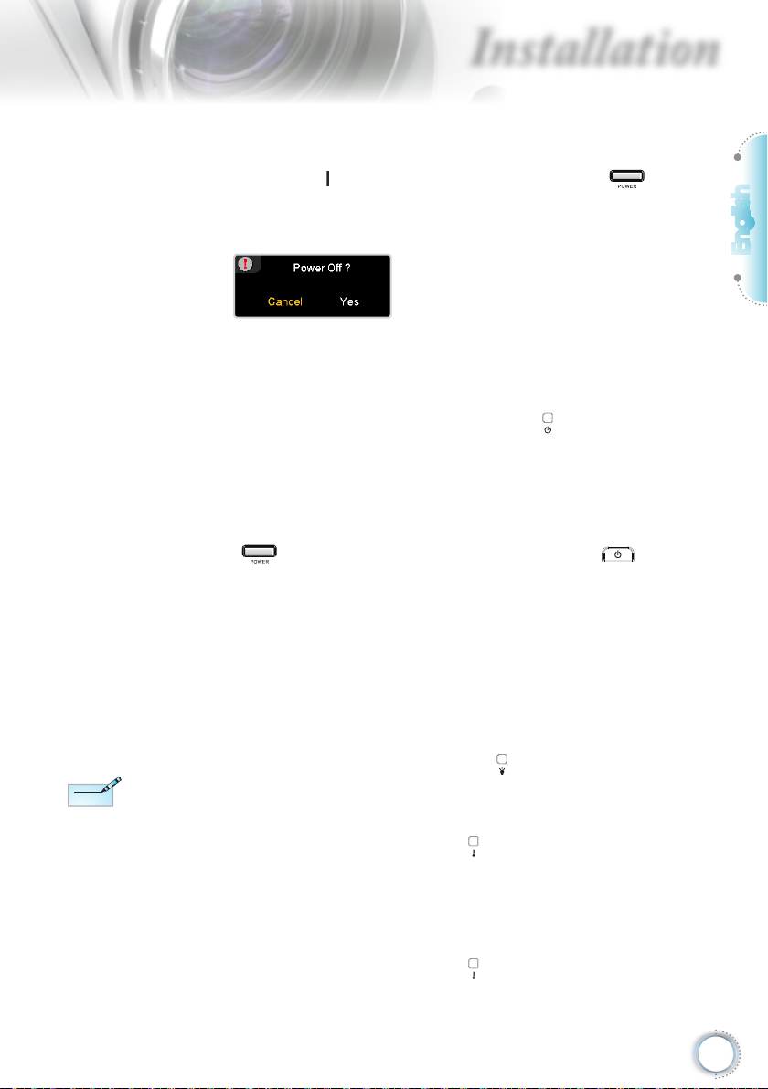
Powering Off the Projector
1. Press the “ ” button on the remote control or “ ” button
on the rear side of the projector two times with one second
interval in between to turn off the projector. First push of
button will display the following message on the screen.
Press the button again to conrm the shut down. If the
button is not pressed, the message will disappear in 5
seconds.
2. The cooling fans continue to operate for about 60 seconds
for cooling cycle and the Power LED “ ” will turn blue.
When the light is solid red, the projector has entered standby
mode.
If you wish to turn the projector back on, you must wait until
the projector has completed the cooling cycle and has
entered standby mode. Once in standby mode, simply press
“ ” button on the rear of the projector or “ ” on the
remote control to restart the projector.
3. Disconnect the power cord from the electrical outlet and the
projector.
4. Do not turn on the projector immediately following a power
off procedure.
English
Contact the nearest
service center if the
projector displays these
symptoms. See page
57 for more information.
Warning Indicator
▀■ When the “LAMP” indicator led “ ” is lit orange, the
projector will automatically shut down. Please call the
nearest Optoma facility for assistance.
▀■ When the “TEMP” indicator “ ” turns red, it indicates the
projector has overheated. The projector will shut down
automatically.
Under normal conditions, the projector can be switched on
again after it has cooled down.
▀■ When the “TEMP” indicator “ ” ashes red, it indicates the
fan has failed.
17
Page 18
Installation
Adjusting the Projected Image
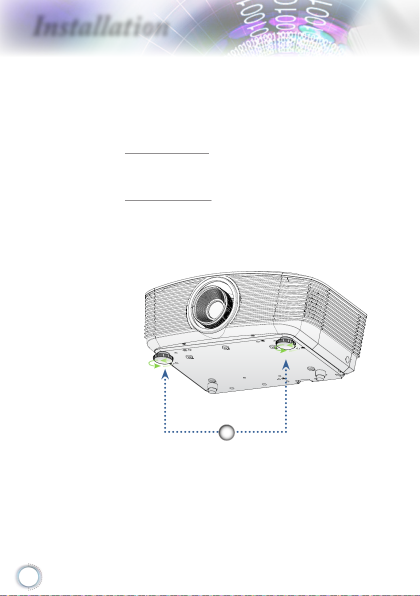
Adjusting the Projector’s Height
The projector is equipped with elevator feet for adjusting
the image height.
To raise the image:
Use screw in foot to raise the image to the desired height
angle and ne-tune the display angle .
To lower the image:
Use screw in foot to lower the image to the desired height
angle and ne-tune the display angle .
18
1
Tilt-Adjustment Feet
Page 19

Installation
Adjusting Projected Image Position Using PureShift
Vertical Lens
Shift Lever
The PureShift feature provides a lens shift function that can be
used to adjust the position of the projected image either
horizontally or vertically within the range detailed below.
PureShift is a unique system that provides lens shift while
maintaining a much higher ANSI contrast ratio than traditional
lens shift systems.
Lens Release
Horizontal Lens
Shift Lever
English
▀■ Adjusting the vertical image position
The vertical image height can be adjusted between 110% and
30% of half image height. Note that the maximum vertical
image height adjustment can be limited by the horizontal image
position. For example it is not possible to achieve the maximum
vertical image position height detailed above if the horizontal
image position is at maximum. Please consult the PureShift
Range diagram below for further clarication.
19
Page 20

Installation
Screen Height
(H)
100%
H x 10%
H x 30%
H x 20%
H x 60%
Distance
(L)
Screen
Left Side
(W/2) x 10% (W/2) x 10%
Right Side
Screen Width
(W)
▀■ Adjusting the horizontal image position
With the lens in the center position the horizontal image
position can be adjusted to the left or right by up to a maximum
of 10% of the half image width. Note that the maximum
horizontal image height adjustment can be limited by the
vertical image position. For example it is not possible to achieve
the maximum horizontal image position if the vertical image
position is at maximum. Please consult the PureShift Range
diagram below for further clarication.
20
Page 21

W
Wx5%
Hx110%
Wx5%
Max W image shift=Wx5%
Max H image shift=Hx110%
When Hx110%, Max image shift=Wx0%
When Wx5%, Max image shift=Hx100%
Hx100%
Hx30%
H=Image Height
TR means “Throw
Note
Note
Ratio”.
Installation
▀■ PureShift Range Diagram
Adjusting Projection Image Size
Standard projection lens: TR: Wide ― 1.54 Tele ― 1.93
Diagonal
length (inch) size
of 16:9 Screen
35 0.77 0.44 2.54 1.43 - 1.50 - 4.91 0.48 1.57
45 1.00 0.56 3.27 1.84 1.53 1.92 5.03 6.31 0.62 2.02
50 1.11 0.62 3.63 2.04 1.70 2.14 5.59 7.01 0.68 2.25
60 1.33 0.75 4.36 2.45 2.05 2.56 6.71 8.41 0.82 2.70
70 1.55 0.87 5.08 2.86 2.39 2.99 7.83 9.81 0.96 3.15
80 1.77 1.00 5.81 3.27 2.73 3.42 8.95 11.21 1.10 3.60
90 1.99 1.12 6.54 3.68 3.07 3.85 10.07 12.62 1.23 4.04
100 2.21 1.25 7.26 4.09 3.41 4.27 11.19 14.02 1.37 4.49
120 2.66 1.49 8.72 4.90 4.09 5.13 13.42 16.82 1.64 5.39
150 3.32 1.87 10.89 6.13 5.11 6.41 16.78 21.03 2.05 6.74
205 4.54 2.55 14.89 8.38 6.99 - 22.93 - 2.81 9.21
This graph is for user’s reference only.
Screen Size W X H (16:9) Projection distance (D)
(m) (feet) (m) (feet)
Width Height Width Height wide tele wide tele (m) (feet)
Offset
(Hd)
English
21
Page 22

Installation
Note
Note
TR means “Throw
Ratio”.
Long throw projection lens: TR: Wide ― 1.93 Tele ― 2.89
Diagonal
length (inch) size
of 16:9 Screen
35 0.77 0.44 2.54 1.43 - 2.24 - 7.35
45 1.00 0.56 3.27 1.84 - 2.88 - 9.45
50 1.11 0.62 3.63 2.04 2.14 3.20 7.01 10.50
60 1.33 0.75 4.36 2.45 2.56 3.84 8.41 12.59
70 1.55 0.87 5.08 2.86 2.99 4.48 9.81 14.69
80 1.77 1.00 5.81 3.27 3.42 5.12 11.21 16.79
90 1.99 1.12 6.54 3.68 3.85 5.76 12.62 18.89
100 2.21 1.25 7.26 4.09 4.27 6.40 14.02 20.99
150 3.32 1.87 10.89 6.13 6.41 9.60 21.03 31.49
200 4.43 2.49 14.53 8.17 8.55 12.80 28.04 41.98
300 6.64 3.74 21.79 12.26 12.82 19.19 42.05 62.97
400 8.86 4.98 29.05 16.34 17.09 25.59 56.07 83.96
468 10.36 5.83 33.99 19.12 20.00 29.94 65.60 98.24
Screen Size W X H (16:9) Projection distance (D)
(m) (feet) (m) (feet)
Width Height Width Height wide tele wide tele (m) (feet)
Offset
(Hd)
0.48 1.57
0.62 2.02
0.68 2.25
0.82 2.70
0.96 3.15
1.10 3.60
1.23 4.04
1.37 4.49
2.05 6.74
2.74 8.99
4.11 13.48
5.48 17.98
6.41 21.03
Short throw projection lens: TR ― 0.77
Diagonal
length (inch) size
of 16:9 Screen
30 0.66 0.37 2.18 1.23 0.51 1.68
45 1.00 0.56 3.27 1.84 0.77 2.52
50 1.11 0.62 3.63 2.04 0.85 2.80
60 1.33 0.75 4.36 2.45 1.02 3.36
70 1.55 0.87 5.08 2.86 1.19 3.91
80 1.77 1.00 5.81 3.27 1.36 4.47
90 1.99 1.12 6.54 3.68 1.53 5.03
100 2.21 1.25 7.26 4.09 1.70 5.59
120 2.66 1.49 8.72 4.90 2.05 6.71
150 3.32 1.87 10.89 6.13 2.56 8.39
175 3.87 2.18 12.71 7.15 2.98 9.79
Screen Size W X H (16:9) Projection distance (D)
(m) (feet)
Width Height Width Height (m) (feet)
(m) (feet)
Offset
(Hd)
0.41 1.35
0.62 2.02
0.68 2.25
0.82 2.70
0.96 3.15
1.10 3.60
1.23 4.04
1.37 4.49
1.64 5.39
2.05 6.74
2.40 7.86
22
Page 23

User Controls
/
Remote Control
Using the Remote Control
Refer to the “Power On the Projector”
Power On/Off
section on page 16.
Refer to the “Power Off the Projector”
section on page 17.
English
Brightness
Contrast
PureEngine
DynamicBlack
Brite Mode
Color
Advanced
Enter
Four Directional
Select Keys
Menu
Mode
Overscan
Adjust the brightness of the image.
Control the degree of difference between
the lightest and darkest parts of the
picture.
The PureEngine is a collection of
advanced image processing technologies
that enhances the quality of the displayed
image.
Enable the projector to automatically
optimize the display of dark movie scenes
enabling them to be shown in incredible
detail. (refer to page 29)
Increase the brightness of the image.
(refer to page 38)
Access the Advanced Color settings.
Access the Advanced Image settings
menu.
Conrm your item selection.
Use directional select keys to select items
or make adjustments to your selection.
Display or exit the on-screen display
menus for projector.
Select the display mode from Cinema,
Reference, Photo, Bright, Graphic, ISF
Day, ISF Night and User.
Mask off a few pixels on each edge of the
image to be displayed. Use the function
to adjust if image source happens to have
noise near any edge of the display image.
23
Page 24

User Controls
Edge Mask
On
Off
4:3
Letter Box
Re-Sync
16:9
Native
VGA
HDMI 1
HDMI 2
HDMI 3
YPbPr
S-Video
Video
Source
Choose “On” to mask off a few pixels on
each edge of the image to be displayed.
Use Edge Mask “On” if image source
happens to have encoding error near any
edge of the displayable image.
Activate the 12V OUT A output.
Deactivate the 12V OUT A output.
Scale the image at a 4:3 aspect ratio.
Enable the viewing of the letterboxed
nonanamorphically enhanced movie at
full screen width. Part of the original
image will be lost if the image aspect ratio
is less than 2.35:1.
Automatically synchronize the projector to
the input source.
Scale the image at a 16:9 aspect ratio.
The input source will be displayed without
scaling.
Press “VGA” to choose source from VGA
connector.
Press “HDMI 1” to choose source from
HDMI 1 connector.
Press “HDMI 2” to choose source from
HDMI 2 connector.
Press “HDMI 3” to choose source from
HDMI 3 connector.
Press “YPbPr” to choose Component
Video source.
Press “S-Video” to choose S-video
source.
Press “Video” to choose Composite Video
source.
Press “Source” to choose RGB,
Component, S-Video, Composite Video,
and HDMI source.
24
Page 25

User Controls
On-screen Display Menus
The Projector has multilingual On-screen Display menus
that allow you to make image adjustments and change a
variety of settings. The projector will automatically detect
the source.
How to operate
1. To open the OSD menu, press “Menu” on the Remote Control or
Control Panel.
2 When OSD is displayed, use keys to select any item in the
main menu. While making a selection on a particular page, press
or “Enter” key to enter sub menu.
3. Use keys to select the desired item and adjust the settings
by key.
4. Select the next item to be adjusted in the sub menu and adjust as
described above.
5. Press “Enter” or “Menu” to conrm, and the screen will return to the
main menu.
6. To exit, press “Menu” again. The OSD menu will close and the
projector will automatically save the new settings.
English
Main Menu
Setting
Sub Menu
25
Page 26

User Controls
Menu Tree
26
Page 27

User Controls
Note
Note
ISF modes are
only available
through an
ISF-certied
calibrator.
Image
Display Mode
There are many factory presets optimized for various types of
images.
Cinema 1/Cinema 2: For home theater.
Reference: This mode is intended to reproduce, as close as
possible, the image the way the movie director intended. Color,
color temperature, brightness, contrast and gamma settings are
all congured to standard reference levels.
Photo: Optimized for displaying photographic images.
Bright: Optimized for maximum brightness.
Graphic: Optimized for viewing of animation and games.
ISF Day: Intended for ISF color alignment.
ISF Night: Intended for ISF color alignment.
User: User adjustable settings.
Contrast
The contrast controls the degree of difference between the lightest
and darkest parts of the picture. Adjusting the contrast changes
the amount of black and white in the image.
Press the to decrease the contrast.
Press the to increase the contrast.
English
27
Page 28

User Controls
Brightness
Adjust the brightness of the image.
Press the to darken image.
Press the to lighten the image.
Color
Adjust a video image from black and white to fully saturated color.
Press the to decrease the color saturation in the image.
Press the to increase the color saturation in the image.
Tint
Adjust the color balance of red and green.
Press the to increase the amount of green in the image.
Press the to increase the amount of red in the image.
Sharpness
Adjust the sharpness of the image.
Press the to decrease the sharpness.
Press the to increase the sharpness.
Advanced
Use this option to enter the Advanced menu see page 29 and 30.
28
Page 29

User Controls
Image | Advanced
Noise Reduction
The motion Adaptive Noise Reduction reduces the amount of
visible noise in interlaced signals. The range is from “0” to “10”.
(0:Off)
Gamma
This allows you to set up gamma curve type. After the initial setup
and ne tuning is completed, utilize the Gamma Adjustment steps
to optimize your image output.
Film: for home theater.
Video: for video or TV source.
Graphics: for image source.
Standard: for standardized setting.
PureEngine
The PureEngine is a collection of advanced image processing
technologies that enhances the quality of the displayed image.
DynamicBlack
DynamicBlack enables the projector to automatically optimize the
display of dark movie scenes enabling them to be shown in
incredible detail (Cinema2: maximum effect).
English
29
Page 30

User Controls
Lens IRIS
This adjustable item opens and closes the len’s iris. The range is
from “1” to “9”.
Color Settings
Color Temperature: Adjust the color temperature. Cold
temperature, the screen looks colder; with Warm temperature,
the screen looks warmer.
Color Gamut: Select this menu to optomize the color gamut
color range for Native, DLP-C, HDTV, EBU or SMPTE-C.
CMS: Select this menu to optimize Color Management
Settings.
RGB Gain/Bias: Press into the next menu as below and then
use or to select item. Use or to select Red, Green, or
Blue for brightness (Gain) and contrast (Bias).
Color Space: Select an appropriate color matrix type from RGB
or YCbCr.
RGB Channel: Select this menu to adjust the RGB Bias and
Gain levels for each primary (RGB) color.
30
Page 31

User Controls
Image | Advanced
| PureEngine
PureDetail
PureDetail is an edge enhancement tool that better denes the
edges in the projected image thus providing more perceived detail.
PureColor
This adjustable item utilizes a new color-processing algorithm and
enhancements to enable the picture’s vividness to be signicantly
increased. The range is from “0” to “5”.
PureMotion
PureMotion uses sophisticated algorithms to ensure that the
natural motion in the image is preserved.
PureEngine Demo
This feature enables you to see the difference in the image quality
between the raw unprocessed image and the image processed by
the PureEngine. Use this mode to check the adjustments that you
make to the PureEngine settings.
English
31
Page 32

User Controls
Format
Use this function to choose your desired aspect ratio.
4:3: This format is for 4x3 input sources.
16:9: This format is for 16x9 input sources, like HDTV and DVD
enhanced for Widescreen TV.
LBX: This format is for non-16x9, letterbox source and for users
who use external anamorphic lens to display 2.35:1 aspect ratio
using full resolution.
Detail informations about LBX mode :
1. Some Letter-Box DVDs are not enhanced for 16x9 TVs. In
this situation, the image will not look right when displayed in
16:9 mode.
In this situation, please try to using the 4:3 mode to view the
DVD.
If the content is not 4:3, there will be black bars around the
image in 16:9 display. For this type of content, you can use
LBX mode to ll the image on the 16:9 display.
2. If you use an external anamorphic lens, this LBX mode also
allows you to watch a 2.35:1 content (include Anamorphic
DVD and HDTV lm source) that support anamorphic wide is
enhanced for 16x9 Display in a wide 2.35:1 image.
In this case, there are no black bars. Lamp power and
vertical resolution are fully utilized.
Display
32
Page 33

Note
Note
When “AUTO235” is
Note
Note
enabled for 12v OUT B,
display “Format” is set
to “Auto235” and cannot be changed.
Each I/O has
different settings of
“Overscan”.
User Controls
Native: This format displays the original image without any
scaling.
Display area
Picture area
Input Signal
Overscan
Overscan function removes the noise in a video image. Overscan
the image to remove video encoding noise on the edge of video
source.
Edge Mask
Press the to reduce the size of an image.
Press the to magnify an image on the projection screen.
V Image Shift
Shift the projected image position vertically.
V Keystone
Press the or to adjust image distortion vertically and make a
squarer image.
Display on Screen
English
33
Page 34

User Controls
Note
Note
SuperWide
SuperWide is a feature that uses a special 2.0:1 aspect ratio
screen enabling both 16:9 and 2.35:1 aspect ratio movies to be
shown without black bars at the top and bottom of the screen
Off: Your desired aspect ratio can be selected - 4:3, 16:9, LBX
“SuperWide” is Off“
as default.
How to use
“SuperWide”
1. Obtain a 2.0:1 aspect
ratio screen
2. Switch SuperWide
ON
3. Align the projector
image correctly on
the screen
4. Enjoy movies without
black bars
and Native.
Auto: To solve the differences of the lm formats, the option
can keep the format in the same ratio.
On: a. On (16:9): Fixed 2.0:1 mode for 16:9 content.
b. On (2.35:1): Fixed 2.0:1 mode for 2.35:1 content.
34
Page 35

User Controls
Note
Note
Rear-Desktop and
Rear-Ceiling are to be
used with a translucent
screen.
System
Menu Location
Choose the menu location on the display screen.
Lamp Settings
Choose this menu to adjust your desired lamp setting.
Projection
Front-Projection
This is the default selection. The image is projected straight on
the screen.
Rear-Desktop
When selected, the image will appear reversed.
Front-Ceiling
When selected, the image will turn upside down.
English
Rear-Ceiling
When selected, the image will appear reversed in upside down
position.
Test Pattern
Display a test pattern. There are Grid, White pattern and None.
Background Color
Use this feature to display a “Dark Blue”, “Gray”, or “Black” screen
when no signal is available.
35
Page 36

User Controls
Startup Image
Select the screen to display during startup.
12V OUT A
12V OUT A provides a standard DC voltage for motorized screens.
12V OUT B
Off: disables the OUT.
On: enables the OUT and the programmable sub-menu. The
sub-menu is accessed by selecting the ON option then
pressing the ENTER button on the remote control. Checking an
option in the sub-menu will activate the OUT when the selected
display mode is selected. In the example below 16:9 has been
selected – this means that OUT B will be active when the
projector display mode is set to 16:9. The OUT will be inactive
for all the other display mode options.
36
Page 37

First time to turn on the
Note
Note
projector:
Remember to select the
type of lens you have
installed.
User Controls
Auto235: When AUTO235 is enabled the projector will
automatically detect when a 2.35:1 ratio presentation is being
shown and will activate the trigger on this port which, in turn,
can be used to activate a motorised anamorphic lens
assembly. The AUTO235 setting and a motorized anamorphic
lens assembly can be used in this way to provide a fully
automated “Constant Height” projection system.
Lens Type
Used to set the lens type that has been tted. This is to ensure
correct operation of the lens iris.
English
37
Page 38

User Controls
Lamp Hour
Display the cumulative lamp operating time.
Lamp Reminder
Choose this function to show or to hide the warning message
when the changing lamp message is displayed. The message will
appear up 30 hours before suggested replacement of lamp.
Brightness Mode
Choose “Bright” to increase the lamp brightness. Choose “STD” to
return to normal mode.
Lamp Reset
Reset the lamp life hour after replacing the lamp.
System | Lamp
Settings
38
Page 39

User Controls
Note
Note
Startup Capture
support in:
HDMI 720p/1080p
VGA 1920X1080@60Hz
YPbPr 720p/1080p
System | Startup
Image
Image
Select the screen to display during startup.
Default — the supplied default startup screen.
User — customized screen capture using the Image Capture
function.
Image Capture
Capture a displayed screen to use as the startup screen.
1. Display the desired screen on the projector.
2. Select Image Capture from the Advanced menu.
3. Select OK. Screen capture in progress will display.
When nished, Screen capture Succeeded will display.
The captured screen is saved as User in the Image menu.
English
39
Page 40

User Controls
Language
Choose the multilingual OSD menu. Press or into the sub
menu and then use the or key to select your preferred
language. Press “Select (Enter)” to nalize the selection.
Input Filter
Enable the input lter. Press or into the next menu as below
and then use or to select. Press “Select (Enter)” to nalize
the selection. The projector will not search inputs that are
de-selected.
Setup
40
Page 41

User Controls
Source Lock
When this function is turned off, the projector will search for other
signals if the current input signal is lost. When this function is
turned on, it will search for a specied connection port.
High Altitude
Choose “On” to turn on High Altitude mode. Operates the fans at
full speed continuously to allow for proper high altitude cooling of
the projector.
Information Hide
Suppress informational messages on the projected screen.
On: No status messages appear on screen during operation.
Off: Status messages appear as normal on screen during
operation.
Auto Power Off
Set the time interval (in minutes) to power off the system if there is
no input signal detected.
Signal
RGB/HDTV Source Video Source
English
HDMI Source
41
Page 42

User Controls
Note
Note
Frequency: Change the display data frequency to match the
frequency of your computer’s graphic card. When you
experience a vertical ickering bar, use this function to make an
adjustment.
Phase: Synchronize the signal timing of the display with the
graphics card. If you experience an unstable or ickering
image, use this function to correct it.
H Position: Adjust the horizontal position.
V Position: Adjust the vertical position.
White Level : Allow user to adjust White Level when inputting
“IRE” is only supported
on NTSC signal.
SVideo or Video/CVBS signals.
Black Level : Allow user to adjust Black Level when inputting
SVideo or Video/CVBS signals.
Saturation : Adjust a video image from black and white to fully
saturated color. Press the to decrease the amount of color in
the image. Press the to increase the amount of color in the
image.
Hue : Adjust the color balance of red and green. Press the
to increase the amount of green in the image. Press the to
increase the amount of red in the image.
IRE : Adjust measurement of composite video signals.
Black Level (for HDMI): Allows user to adjust the Black Level
for HDMI signals.
Reset
Return the adjustments and settings to factory default values.
Current : Return the current menu’s settings to factory default.
All : Return the settings for all menus to factory default values.
42
Page 43

Appendices
Troubleshooting
If you experience a problem with your projector,
please refer to the following information. If a
problem persists, please contact your local reseller
or service center.
Image Problems
No image appears on-screen
Ensure all the cables and power connections are correctly and
securely connected as described in the “Installation” section.
Ensure the pins of connectors are not crooked or broken.
Check if the projection lamp has been securely installed. Please
refer to the “Replacing the Lamp” section.
Make sure you have removed the lens cap and the projector is
switched on.
Image is out of focus
Make sure the Lens cap is removed.
Adjust the Focus Ring on the projector lens.
Make sure the projection screen is between the required distance
from the projector. See pages 21 and 22.
English
The image is stretched when displaying 16:9 DVD title
When you play anamorphic DVD or 16:9 DVD, the projector will
show the best image in 16: 9 format on projector side.
If you play the LBX format DVD title, please change the format as
LBX in projector OSD.
If you play 4:3 format DVD title, please change the format as 4:3 in
projector OSD.
If the image is still stretched, you will also need to adjust the aspect
ratio by referring to the following:
Please setup the display format as 16:9 (wide) aspect ratio type on
your DVD player.
43
Page 44

Appendices
Image is too small or too large
Adjust the zoom lever from the lens.
Move the projector closer to or further from the screen.
Press [Menu] on the projector panel, go to “Display-->Format”.
Try the different settings.
Image has slanted sides:
If possible, reposition the projector so that it is centered on the
screen and below the bottom of the screen and use PureShift to
make adjustments to the image position.
Use “Display-->V Keystone” from the OSD to make an adjustment.
Image is reversed
Select “System-->Projection” from the OSD and adjust the
projection direction.
Other Problems
The projector stops responding to all controls
If possible, turn off the projector, then unplug the power cord and
wait at least 20 seconds before reconnecting power.
44
Lamp burns out or makes a popping sound
When the lamp reaches its end of life, it will burn out and may
make a loud popping sound. If this happens, the projector will not
turn on until the lamp module has been replaced. To replace the
lamp, follow the procedures in the “Replacing the Lamp” section on
page 48.
Page 45

Appendices
Note
Note
Projector Status Indication
Steady light =>
No light =>
Power LED
Message
(Blue)
Standby State
(Input power cord)
Standby State
(Burn in Mode)
Power on with OSD
(Press power button)
Power on without OSD
Over Temperature
Fan Fail
Lamp error
Power off (Cooling)
* Power LED will be ON when OSD appears and OFF when OSD disappears.
Flashing
*
Power LED
(Red)
Temp-LED“
(Red)
Flashing
Lamp-LED
(Red)
English
45
Page 46

Appendices
LED Error Code Messages
Power LED
Error Code Message
(Blink)
T1 temperature over temperature 3 0
Thermal Break 4 0
G794 fail 4 4
T1 fail 4 5
Lamp error 5 0
Ballast Over Temperature 5 1
Ballast shot circuit in output detected 5 2
End of lamp lift detected 5 3
Ballast lamp did not ignite 5 4
Lamp extinguished during normal operation 5 5
Lamp extinguished during run-up phase 5 6
Fan1 error (Lamp Fan) 6 1
Fan2 error (Ballast Fan) 6 2
Fan3 error (Burner Fan) 6 3
Fan4 error (Power Fan) 6 4
Lamp LED
(Blink)
46
Lamp door open 7 0
DMD error 8 0
Color wheel error 9 0
Page 47

Appendices
LED states
On Screen Messages
Fan failed:
The projector will switch off automatically.
Over temperature:
The projector will switch off automatically.
Replacing the lamp:
Lamp is approaching the end of its rated life.
Replacement suggested.
English
Remote Control Problems
If the remote control does not work
Check the operating angle of the remote control is within ±15° both
horizontally and vertically of on of the IR receivers on the projector.
Make sure there are no any obstructions between the remote con-
trol and the projector. Move to within 7 m (23 ft) of the projector.
Make sure batteries are inserted correctly.
Replace batteries if they are exhausted.
47
Page 48

Appendices
Replacing the Lamp
The projector automatically detects the lamp life. When the
lamp life is nearing the end of use, you will receive a warning
message.
When you see this message, please contact your local
reseller or service center to change the lamp as soon as
possible. Make sure the projector has been cooled down for
at least 30 minutes before changing the lamp.
Warning: Lamp compartment is hot! Allow it to cool down before
changing lamp!
48
Warning: To reduce the risk of personal injury, do not drop the lamp
module or touch the lamp bulb. The bulb may shatter and cause
injury if it is dropped.
Page 49

Appendices
1
2
3
English
4
5
49
Page 50

Appendices
Lamp Replacing Procedure:
1. Switch off the power to the projector by pressing the Power button.
2. Allow the projector to cool down at least 30 minutes.
3. Disconnect the power cord.
4. Unlock the lamp cover.
5. Pull up and remove the cover.
6. Use a screwdriver to remove the screws from the lamp module.
7. Pull out the lamp module.
To replace the lamp module, reverse the previous steps.
8. Turn on the projector and do “Lamp Reset” after the lamp module
is replaced.
Lamp Reset: (i)Press “Menu” -> (ii)Select “System” -> (iii)Select
“Lamp Settings” ->(iv)Select “Lamp Reset” -> (v)Select “Yes”.
50
Page 51

Appendices
Compatibility Modes
Mode Resolution
800 x 600 56
800 x 600 60
SVGA
XGA
WXGA
HD
SXGA+ 1400 x 1050 60
UXGA 1600 x 1200 60
800 x 600 72
800 x 600 75
800 x 600 85
1024 x 768 60
1024 x 768 70
1024 x 768 75
1024 x 768 85
1280 x 768 60
1280 x 800 60
1280 x 720 60
1280 x 1024 60
1280 x 1024 75
1920 x 1080 24
1920 x 1080 60
Power Book G4
SVGA 800 x 600 60
800 x 600 75
800 x 600 85
XGA 1024 x 768 60
1024 x 768 70
1024 x 768 75
1024 x 768 85
WXGA 1280 x 768 60
HD 1280 x 720 60
1280 x 1024 60
1280 x 1024 75
SXGA+ 1400 x 1050 60
UXGA 1600 x 1200 60
iMAC
XGA 1024 x 768 60
V.Frequency
(Hz)
AAnalog Digital
English
51
Page 52

Appendices
RS232 Commands and Protocol
Function List
RS232 Pin Assignments
31 5
6
Pin no. Name I/O (From Projector Side)
1 NC __
2 RXD IN
3
4 NC __
5 NC __
6 NC __
7 RS232 RTS
8 RS232 CTS
9 NC __
TXD
9
OUT
52
Page 53

Appendices
HD86 RS232 Command Table.
----------------------------------------------------------------------------------------------------------------------------------------------------------------------------------------Baud Rate : 9600
Data Bits: 8
Parity: None
Stop Bits: 1
Flow Control : None
UART16550 FIFO: Disable
Proje
ctor Return (Pass): P
Projector Return (Fail): F
XX=01-99, projector's ID, XX=00 is for all projectors
-----------------------------------------------------------------------------------------------------------------------------------------------------------------------------------------
SEND to projector Note : There is a <CR> after all ASCII commands
0D is the HEX code for <CR> in ASCII code
-----------------------------------------------------------------------------------------------------------------------------------------------------------------------------------------
232 ASCII Code HEX Code
Function Description
----------------------------------------------------------------------------------------------------------------------------------------------------------------------------------------~XX00 1 7E 30 30 30 30 20 31 0D Power ON
~XX00 2 7E 30 30 30 30 20 32 0D Power OFF
----------------------------------------------------------------------------------------------------------------------------------------------------------------------------------------~XX01 1 7E 30 30 30 31 20 31 0D Resync
~XX12 1 7E 30 30 31 32 20 31 0D H
DMI 1
~X
X12 15 7E 30 30 31 32 20 31 35 0D HDMI 2
~X
X12 16 7E 30 30 31 32 20 31 36 0D HDMI 3
~
X
X12 14 7E 30 30 31 32 20 31 34 0D Compone
n
t YPbPr
~XX12 5 7E 30 30 31 32 20 35 0D VGA
~XX12
7 7E 30 30 31 32 20 37 0D Direct Source Selection VGA SCART
~XX12 8 7E 30 30 31 32 20 38 0D VGA Compo
nent
~XX12 9 7E 30 30 31 32 20 39 0D S-video
~XX12 10 7E 30 30 31 32 20 31 30 0D Video
---
--------------------------------------------------------------------------------------------------------------------------------------------------------------------------------------
~XX20 1 7E 30 30 32 30 20 31 0D Display Mode C
inema 1
~XX20 9 Cinema
2
~XX20 2 7E 30 30 32 30 20 32 0D Bright
~
XX20 3 7E 30 30 32 30 20 33 0D Photo
~X
X20 4 7E 30 30 32 30 20 34 0D Referen
c
e
~XX20 10 Graphic
s
~XX20 5 7E 30 30 32 30 20 35 0D User
~X
X20 6 7E 30 30 32 30 20 36 0D ISFDay
~XX20 7 7E 30 30 32 30 20 37 0D ISFNight
-
----------------------------------------------------------------------------------------------------------------------------------------------------------------------------------------
~XX21 n 7E 30 30 32 31 20 a 0D Brightness
n= 0 (a=30) - +100 (a=31 30 30)
~XX22 n 7E 30 30 32 32 20 a 0D Contrast
n= 0
(a=30) - +100 (a=31 30 30)
~XX23 n 7E 30 30 32 33 20 a 0D Sharpness n= 1
(a=31) - +15 (a=31 35)
~XX44 n 7E 30 30 34 34 20 a 0D Color
n= 0
(a=30) - +100 (a=31 30 30)
~XX45 n 7E 30 30 34 35 20 a 0D Tint
n= 0
(a=30) - +100 (a=31 30 30)
----------------------------------------------------------------------------------------------------------------------------------------------------------------------------------------~XX196 n 7E 30 30 31 39 36 20 a 0D Image/Advanced N
oise Re
duction n= 0 (a=30) - 10 (a=31 30)
~XX35 1 7E 30 30 33 35 20 31 0D Image/Advanced/Gamma Film
~XX182 n 7E 30 30 31 38 32 20 a 0D
Curve T
ype n=-7 (a=2D 37) - +7 (a=37)
~XX183 n 7E 30 30 31 38 33 20 a 0D Offset
n=-5 (a=2D 35) - +5 (a=35)
~XX35 2 7E 30 30 33 35 20 32 0D Video
~XX
184 n 7E 30 30 31 38 34 20 a 0D Curve T
y
pe n=-7 (a=2D 37) - +7 (a=37)
~XX185 n 7E 30 30 31 38 35 20 a 0D Offset
n=-5 (a=2D 35) - +5 (a=35)
~XX35 3 7E 30 30 33 35 20 33 0D Graphics
~XX186 n 7E 30 30 31 38 36 20 a 0D Curve
T
ype n=-7 (a=2D 37) - +7 (a=37)
~XX187 n 7E 30 30 31 38 37 20 a 0D Offset
n=-5 (a=2D 35) - +5 (a=35)
~XX35 4 7E 30 30 33 35 20 34 0D Standar
d
~
XX188 n 7E 30 30 31 38 38 20 a 0D Curve
T
ype n=-7 (a=2D 37) - +7 (a=37)
~XX189 n 7E 30 30 31 38 39 20 a 0D Offset
n=-5 (a=2D 35) - +5 (a=35)
~XX41 n 7E 30 30 34 31 20 a 0D Image/Advanced/PureEngine PureDetail n=Off/1/2/3 (a=30/31/32/33)
~XX42 n 7E 30 30 34 32 20 a 0D P
ureColo
ur n=Off/1/2/3/4/5 (a=30/31/32/33/34/35)
~XX190 n 7E 30 30 31 39 30 20 a 0D PureMot
i
on n=Off/Low/Med/High (a=30/31/32/33/34)
~XX197 n 7E 30 30 31 39 37 20 a 0D Pure De
m
o n=Off/H Spilt/V Spilt=0/1/2 (a=30/31/32)
~XX191 n 7E 30 30 31 39 31 20 a 0D DynamicBlack
n=Off
/Cinema 1/Cinema 2=1(a=30/31/32)
~XX210 n 7E 30 30 33 36 20 31 0D Color Temp. D50/D65
/
/D75/D83/D93/Native n=1/2/3/4/5/6 (a=30/31/32/33/34/35)
~XX211 n Color Ga
mut Native/DLP/HDTV/EBU/SMPTE-C n=Off/1/2/3/4/5 (a=30/31/32/33/34/35)
~XX212 n CMS
R/G/B
/C/Y/M (a=30/31/32/33/34/35/36)
~XX213 n X Offse
t
n= -50 (a=2D 35 30) - +50 (a=35 30)
~XX214 n Y Offse
t
n= -50 (a=2D 35 30) - +50 (a=35 30)
~XX24 n 7E 30 30 32 34 20 a 0D RGB Gain\Bias Red Gai
n
n= -50 (a=2D 35 30) - +50 (a=35 30)
~XX25 n 7E 30 30 32 35 20 a 0D Green Ga
in n= -50 (a=2D 35 30) - +50 (a=35 30)
~XX26 n 7E 30 30 32 36 20 a 0D Blue Gai
n n= -50 (a=2D 35 30) - +50 (a=35 30)
~XX27 n 7E 30 30 32 37 20 a 0D Red Bias
n= -50 (a=2D 35 30) - +50 (a=35 30)
~XX28 n 7E 30 30 32 38 20 a 0D Green B
i
as n= -50 (a=2D 35 30) - +50 (a=35 30)
~XX29 n 7E 30 30 32 39 20 a 0D Blue Bi
a
s n= -50 (a=2D 35 30) - +50 (a=35 30)
~XX37 n 7E 30 30 33 37 20 32 0D Color Space AUTO/RG
B
/YUV(YCbCr) n=1/2/3 (a=30/31/32)
----------------------------------------------------------------------------------------------------------------------------------------------------------------------------------------~XX60 1 7E 30 30 36 30 20 31 0D Format 4:3
~XX
60 2 7E 30 30 36 30 20 32 0D 16:9
~XX60 5 7E 30 30 36 30 20 35 0D LBX
~XX
6
0 6 7E 30 30 36 30 20 36 0D Native
~
X
X60 8 7E 30 30 36 30 20 38 0D AUTO235
~
XX60 9 7E 30 30 36 30 20 39 0D SuperWid
e
~XX60 7 7E 30 30 36 30 20 37 0D AUTO
----
-------------------------------------------------------------------------------------------------------------------------------------------------------------------------------------
RS232 Protocol Function List
English
53
Page 54

Appendices
~XX61 n 7E 30 30 36 31 20 a 0D Overscan n= 0 (a=30) – 4 (a=34)
~XX62 n 7E 30 30 36 32 20 a 0D Edge masking
n=0 (
a=30) -5 (a=35)
~XX64 n 7E 30 30 36 34 20 a 0D V Image Shift
n=
-
50 (a=2D 35 30) - +50 (a=35 30)
~XX66 n 7E 30 30 36 36 20 a 0D V Keystone n= -
30 (a=2D 33 30) - +30 (a=33 30)
-----------------------------------------------------------------------------------------------------------------------------------------------------------------------------------------
~XX72 1 7E 30 30 37 32 20 31 0D Menu Location T
op Left
~XX72 2 7E 30 30 37 32 20 32 0D Top Righ
t
~XX72 3 7E 30 30 37 32 20 33 0D Center
~XX72 4 7E 30 30 37 32 20 34 0D Bottom
L
eft
~XX72 5 7E 30 30 37 32 20 35 0D Bottom R
ight
-----------------------------------------------------------------------------------------------------------------------------------------------------------------------------------------
~XX108 1 7E 30 30 31 30 38 20 31 0D Lamp Setting Lamp Hou
r
~XX109 1 7E 30 30 31 30 39 20 31 0D Lamp Re
m
inder On
~XX109 2 7E 30 30 31 30 39 20 32 0D
Off
~
XX110 1 7E 30 30 31 31 30 20 31 0D Brite Mo
de On
~XX110 2 7E 30 30 31 31 30 20 32 0D
Off
~
XX111 1 7E 30 30 31 31 31 20 31 0D Lamp Re
s
et Yes
~XX111 2 7E 30 30 31 31 31 20 32 0D No
-----
------------------------------------------------------------------------------------------------------------------------------------------------------------------------------------
~XX71 1 7E 30 30 37 31 20 31 0D Projection Fr
ont-Des
ktop
~XX71 2 7E 30 30 37 31 20 32 0D Rear-Des
ktop
~XX71 3 7E 30 30 37 31 20 33 0D Front-Ce
i
ling
~XX71 4 7E 30 30 37 31 20 34 0D Rear-Cei
ling
-----------------------------------------------------------------------------------------------------------------------------------------------------------------------------------------
~XX70 1 7E 30 30 37 30 20 31 0D Language E
nglish
~XX70 2 7E 30 30 37 30 20 32 0D German
~XX70 3 7E 30 30 37 30 20 33 0D French
~XX70 4 7E 30 30 37 30 20 34 0D Italian
~XX70 5 7E 30 30 37 30 20 35 0D Spanish
~XX70 6 7E 30 30 37 30 20 36 0D Portugu
e
se
~XX70 7 7E 30 30 37 30 20 37 0D Polish
~XX70 8 7E 30 30 37 30 20 38 0D Dutch
~XX70 9 7E 30 30 37 30 20 39 0D Swedish
~XX70 10 7E 30 30 37 30 20 31 30 0D Norwegia
n
/Danish
~XX70 11 7E 30 30 37 30 20 31 31 0D Finnish
~XX70 12 7E 30 30 37 30 20 31 32 0D Greek
~XX70 13 7E 30 30 37 30 20 31 33 0D Traditi
o
nal Chinese
~XX70 14 7E 30 30 37 30 20 31 34 0D Simplifi
ed Chinese
~XX70 15 7E 30 30 37 30 20 31 35 0D Japanes
e
~XX70 16 7E 30 30 37 30 20 31 36 0D Korean
~XX70 17 7E 30 30 37 30 20 31 37 0D Russian
~XX70 18 7E 30 30 37 30 20 31 38 0D Hungaria
n
~XX70 19 7E 30 30 37 30 20 31 39 0D Czechos
l
ovak
~XX70 20 7E 30 30 37 30 20 32 30 0D Arabic
~XX70 21 7E 30 30 37 30 20 32 31 0D Thai
~XX
70 22 7E 30 30 37 30 20 32 32 0D Turkish
~
XX39 1 7E 30 30 33 39 20 31 0D Input Source Filters HDMI 1
~X
X39 7 7E 30 30 33 39 20 37 0D HDMI 2
~X
X39 12 7E 30 30 33 39 20 31 32 0D HDMI 3
~
X
X39 8 7E 30 30 33 39 20 38 0D Compone
nt
~XX39 5 7E 30 30 33 39 20 35 0D VGA
~XX
39 9 7E 30 30 33 39 20 39 0D S-Video
~XX39 10 7E 30 30 33 39 20 31 30 0D Video
~XX
100 1 7E 30 30 31 30 30 20 31 0D Source Lock On
~XX10
0 2 7E 30 30 31 30 30 20 32 0D Off
~XX10
6 n 7E 30 30 31 30 36 20 a 0D Auto Power Off (min) n=0 (a=30)-60 (a=36 30) (multiple of 5)
-----------------------------------------------------------------------------------------------------------------------------------------------------------------------------------------
~XX73 n 7E 30 30 37 33 20 a 0D Signal Tracking
(Frequency) n= 0 (a=30) –200 (a=32 30 30)
~XX74 n 7E 30 30 37 34 20 a 0D Phase
n= 0 (a=30) – 100 (a=31 30 30)
~XX75 n 7E 30 30 37 35 20 a 0D H. Posit
ion n= 0 (a=30) – 100 (a=31 30 30)
~XX76 n 7E 30 30 37 36 20 a 0D V. Posit
ion n= 0 (a=30) – 100 (a=31 30 30)
~XX200 n 7E 30 30 32 30 30 20 a 0D Black Le
vel n=0 (a=30) -100 (a=31 30 30)
~XX201 n 7E 30 30 32 30 31 20 a 0D White Le
vel n=0 (a=30) -100 (a=31 30 30)
~XX202 n 7E 30 30 32 30 32 20 a 0D Saturati
on n= 0 (a=30) – 100 (a=31 30 30)
~XX203 n 7E 30 30 32 30 33 20 a 0D Hue n=
0 (a=30) – 100 (a=31 30 30)
~XX204 n 7E 30 30 32 30 34 20 a 0D IRE
n
=
0/7.5 (a=30/31)
~XX217 1 HDMI Bl
a
ck Level YCbCr
~XX217 2 RGB
~XX21
7 3 AUTO
----
-------------------------------------------------------------------------------------------------------------------------------------------------------------------------------------
Remote Control Emulation
~XX14
0 n 7E 30 30 31 34 20 a 0D
Up n=1
0
Left
n
=11
Enter
n=12
Right
n=13
Down n
=14
Menu
n
=20
Re-sync
n=28
-----------------------------------------------------------------------------------------------------------------------------------------------------------------------------------------
54
Page 55

Appendices
SEND from projector automatically
-----------------------------------------------------------------------------------------------------------------------------------------------------------------------------------------
232 ASCII Code HEX Code
Function Projector Return Description
----------------------------------------------------------------------------------------------------------------------------------------------------------------------------------------when Standby/Warming/Cooling/Out of Range/Lamp fail INFOn n :
0/1/2/3/4 = Standby/Warming/Cooling/Lamp fail
-----------------------------------------------------------------------------------------------------------------------------------------------------------------------------------------
READ from projector
-----------------------------------------------------------------------------------------------------------------------------------------------------------------------------------------
232 ASCII Code HEX Code
Function Projector Return Description
----------------------------------------------------------------------------------------------------------------------------------------------------------------------------------------~XX121 1 7E 30 30 31 32 31 20 31 0D Input Source Commands OKn n: 0/1/
2
/3/4/5/6/7/8
= None/HDMI 1/HDMI 2/DVI/Component/VGA/S-Video/Video
~XX122 1 7E 30 30 31 32 32 20 31 0D Software Version OKaaaa
~
XX123 1 7E 30 30 31 32 33 20 31 0D Display Mode OKn n: 0/
1/2/3/4/5/6/7/8/9
= Cinema 1/Cinema 2/Bright/ Photo/ Reference/Graphics/User
1/ ISF Day /ISF Night
~XX124 1 7E 30 30 31 32 34 20 31 0D Power State OKn n: 0/
1=Off/On
~XX125 1 7E 30 30 31 32 35 20 31 0D Brightness OKn
~XX12
6 1 7E 30 30 31 32 36 20 31 0D Contrast OKn
~XX12
7 1 7E 30 30 31 32 37 20 31 0D Aspect Ratio OKn n: 0/
1/2/3/4/5/6
=4:3, 16:9, LBX, Native, AUTO235, SuperWide, AUTO
~XX128 1 7E 30 30 31 32 38 20 31 0D Color Temperature OKn n: 0/
1/2/4/5/6/7/8 =Warm/Medium/Cold/D50/D65/D75/D83/D93/Native
~XX129 1 7E 30 30 31 32 39 20 31 0D Projection Mode OKn n: 0/
1/2/3
=Front-Desktop/Rear-Desktop/Front-Ceiling/Rear-Ceiling
~XX150 1 7E 30 30 31 35 30 20 31 0D Information OKabbbbc
dddde a : 0/1=Off/On
bbbb: La
mp Hour
c: sourc
e 0/1/2/3/4/5/6/7
= None/HDMI 1/HDMI 2/DVI/Component/VGA/S-Video/Video
d
ddd: FW
version
e : Disp
lay mode 0/1/2/3/4/5/7/8/9
= Cinema 1/Cinema 2/Bright/ Photo/ Reference/Graphics/User
1/ ISF Day /ISF Night
~XX151 1 7E 30 30 31 35 31 20 31 0D Model Name OKn n : 0
/1/2/3=HD82/HD82LV/HD86
~XX152 1 7E 30 30 31 35 32 20 31 0D RS232 Version No OKn
English
55
Page 56

Appendices
Note
Note
68.50
100.00
160.50
141.50
141.50
88.00
26.50
165.00
354.41
85.49
20.00
130.00
240.00
260.00
430.97
( 1.024" )
( 1.697" )
( 0.945" )
( 0.512" )
( 0.079" )
( 0.337" )
( 0.557" )
( 0.632" )
160.50
( 0.632" )
( 0.557" )
( 0.270" ) ( 0.394" )
( 0.650" )
( 1.395" )
( 0.104" )
( 0.346" )
Ceiling Mount Installation
1. To prevent damage to your projector, please use the
2. If you wish to use a third party ceiling mount kit, please
Please note that
damage resulting from
incorrect installation will
invalidate the warranty.
Warning:
1. If you buy ceiling
mount from other
company, please
be sure to use the
correct screw size.
Screw size will be
different on different
mounts. It depends
on the plate
thickness.
2. Be sure to keep
at least 10cm gap
between the ceiling
and the bottom of the
projector.
3. Avoid installing the
projector near a heat
source.
Optoma ceiling mount.
ensure the screws used to attached a mount to the
projector met the following specications:
Screw type: M4
Maximum screw length: 11mm
Minimum screw length: 9mm
56
Page 57

Appendices
Optoma Global Ofces
For service or support please contact your local ofce.
USA
715 Sycamore Drive Tel : 408-383-3700
Milpitas, CA 95035, USA Fax: 408-383-3702
www.optomausa.com
Canada
5630 Kennedy Road, Mississauga, Tel : 905-361-2582
ON, L4Z 2A9, Canada Fax: 905-361-2581
www.optoma.ca
Europe
42 Caxton Way, The Watford Business Park
Watford, Hertfordshire,
WD18 8QZ, UK Tel : +44 (0) 1923 691 800
www.optoma.eu Fax: +44 (0) 1923 691 888
Service Tel : +44 (0)1923 691865
France
Bâtiment E Tel : +33 1 41 46 12 20
81-83 avenue Edouard Vaillant Fax: +33 1 41 46 94 35
92100 Boulogne Billancourt, France
Spain
C/ José Hierro,36 Of. 1C Tel : +34 91 499 06 06
28529 Rivas VaciaMadrid, Fax: +34 91 670 08 32
Spain
Deutschland
Werftstrasse 25 Tel : +49 (0) 211 506 6670
D40549 Düsseldorf, Fax: +49 (0) 211 506 66799
Germany
Scandinavia
Grev Wedels Plass 2 Tel : +47 32 26 89 90
3015 Drammen Fax: +47 32 83 78 98
Norway
Latin America
715 Sycamore Drive Tel : 408-383-3700
Milpitas, CA 95035, USA Fax: 408-383-3702
www.optoma.com.br www.optoma.com.mx
Service : services@optoma.com
Service :
Service : service@tsc-europe.com
Service : savoptoma@optoma.fr
Service : info@optoma.de
Service : info@optoma.de
canadacsragent@optoma.com
English
57
Page 58

Appendices
Taiwan
231,台北縣新店市民權路108號5樓
電話:+886-2-2218-2360 傳真:+886-2-2218-2313
服務處:services@optoma.com.tw www.optoma.com.tw
Hong Kong
Unit A, 27/F Dragon Centre, 79 Wing Hong Street,
Cheung Sha Wan Kowloon, Hong Kong
Tel : +852-2396-8968 Fax: +852-2370-1222
www.optoma.com.hk
China
上海市长宁区凯旋路1205号5楼 电话:+86-21-62947376
邮编: 200052 传真:+86-21-62947375
www.optoma.com.cn
Japan
東京都足立区綾瀬 3-25-18 サポートセンター:0120-46-5040
株式会社オーエスエム
E-Mail: info@osscreen.com http://www.os-worldwide.com/
Korea
WOOMI TECH.CO.,LTD.
4F, Minu Bldg.33-14, Nonhyun-Dong, Tel : +82+2+34430004
Kangnam-Ku, seoul, 135-815, KO-
REA
asia.optoma.com
Fax: +82+2+34430005
58
Page 59

Appendices
Regulation & Safety Notices
This appendix lists the general notices of your Projector.
FCC notice
This device has been tested and found to comply with the limits
for a Class B digital device pursuant to Part 15 of the FCC rules.
These limits are designed to provide reasonable protection
against harmful interference in a residential installation. This
device generates, uses and can radiate radio frequency energy
and, if not installed and used in accordance with the
instructions, may cause harmful interference to radio
communications.
However, there is no guarantee that interference will not
occur in a particular installation. If this device does cause
harmful interference to radio or television reception, which can
be determined by turning the device off and on, the user is
encouraged to try to correct the interference by one or more of
the following measures:
Reorient or relocate the receiving antenna.
▀■
Increase the separation between the device and
▀■
receiver.
Connect the device into an outlet on a circuit different
▀■
from that to which the receiver is connected.
Consult the dealer or an experienced radio/television
▀■
technician for help.
Notice: Shielded cables
All connections to other computing devices must be made
using shielded cables to maintain compliance with FCC
regulations.
English
Caution
Changes or modications not expressly approved by the
manufacturer could void the user’s authority, which is
granted by the Federal Communications Commission, to
operate this projector.
59
Page 60

Appendices
Operation conditions
This device complies with Part 15 of the FCC Rules. Operation
is subject to the following two conditions:
1. This device may not cause harmful interference and
2. This device must accept any interference received,
including interference that may cause undesired
operation.
Notice: Canadian users
This Class B digital apparatus complies with Canadian
ICES-003.
Remarque à l’intention des utilisateurs
canadiens
Cet appareil numerique de la classe B est conforme a la norme
NMB-003 du Canada.
Declaration of Conformity for EU countries
EMC Directive 2004/108/EC (including amendments)
▀■
Low Voltage Directive 2006/95/EC
▀■
R & TTE Directive 1999/5/EC
▀■
(if product has RF function)
60
Disposal instructions
Do not throw this electronic device into the
trash when discarding. To minimize
pollution and ensure utmost protection of
the global environment, please recycle it.
 Loading...