

Page 1

Form 2267
groov EPIC
USER’S GUIDE
Page 2

Page 3

groov EPIC
USER’S GUIDE
for
GRV-EPIC-PR1
Form 2267-200618—June 2020
43044 Business Park Drive • Temecula • CA 92590-3614
Phone: 800-321-OPTO (6786) or 951-695-3000
Fax: 800-832-OPTO (6786) or 951-695-2712
www.opto22.com
Product Support Services
800-TEK-OPTO (835-6786) or 951-695-3080
Fax: 951-695-3017
Email: support@opto22.com
Web: support.opto22.com
groov EPIC User’s Guide
i
Page 4

groov EPIC User’s Guide
Form 2267-200618—June 2020
Copyright © 2018-2020 Opto 22.All rights reserved.
Printed in the United States of America.
The information in this manual has been checked carefully and is believed to be accurate; however, Opto 22 assumes no
responsibility for possible inaccuracies or omissions. Specifications are subject to change without notice.
Opto 22 warrants all of its products to be free from defects in material or workmanship for 30 months from the
manufacturing date code. This warranty is limited to the original cost of the unit only and does not cover installation, labor,
or any other contingent costs. Opto 22 I/O modules and solid-state relays with date codes of 1/96 or newer are guaranteed
for life. This lifetime warranty excludes reed relay modules, groov and SNAP serial communication modules, SNAP PID
modules, and modules that contain mechanical contacts or switches. Opto 22 does not warrant any product, components,
or parts not manufactured by Opto 22; for these items, the warranty from the original manufacturer applies. Refer to Opto
22 form 1042 for complete warranty information.
Wired+Wireless controllers and brains are licensed under one or more of the following patents: U.S. Patent No(s). 5282222,
RE37802, 6963617; Canadian Patent No. 2064975; European Patent No. 1142245; French Patent No. 1142245; British Patent
No. 1142245; Japanese Patent No. 2002535925A; German Patent No. 60011224.
Opto 22 FactoryFloor, groov, groov EPIC, groov RIO, mobile made simple, Optomux, and Pamux are registered trademarks of
Opto 22. Generation 4, groov Server, ioControl, ioDisplay, ioManager, ioProject, ioUtilities, mistic, Nvio, Nvio.net Web Portal,
OptoConnect, OptoControl, OptoDataLink, OptoDisplay, OptoEMU, OptoEMU Sensor, OptoEMU Server, OptoOPCServer,
OptoScript, OptoServer, OptoTerminal, OptoUtilities, PAC Control, PAC Display, PAC Manager, PAC Project, PAC Project Basic,
PAC Project Professional, SNAP Ethernet I/O, SNAP I/O, SNAP OEM I/O, SNAP PAC System, SNAP Simple I/O, SNAP Ultimate
I/O, and Wired+Wireless are trademarks of Opto 22.
ActiveX, JScript, Microsoft, MS-DOS, VBScript, Visual Basic, Visual C++, Windows, and Windows Vista are either registered
trademarks or trademarks of Microsoft Corporation in the United States and other countries. Linux is a registered
trademark of Linus Torvalds. ARCNET is a registered trademark of Datapoint Corporation. Modbus is a registered trademark
of Schneider Electric, licensed to the Modbus Organization, Inc. Wiegand is a registered trademark of Sensor Engineering
Corporation. Allen-Bradley, CompactLogix, ControlLogix, MicroLogix, SLC, and RSLogix are either registered trademarks or
trademarks of Rockwell Automation. CIP and EtherNet/IP are trademarks of ODVA. Raspberry Pi is a trademark of the
Raspberry Pi Foundation. The registered trademark Ignition by Inductive Automation® is owned by Inductive Automation
and is registered in the United States and may be pending or registered in other countries. CODESYS® is a registered
trademark of 3S-Smart Software Solutions GmbH.
groov includes software developed by the OpenSSL Project for use in the OpenSSL Toolkit. (http://www.openssl.org)
All other brand or product names are trademarks or registered trademarks of their respective companies or organizations.
ii
groov EPIC User’s Guide
Opto 22
Automation Made Simple.
The equipment covered by this report is considered to be a component intended to be professionally configured/installed
into another manufacturer’s end-product equipment. Also the equipment is intended to be mounted in an #IP54
enclosure according to the manual. No cleaning instruction is provided in manual. Therefore, testing and evaluation for the
requirements of these clauses is not considered necessary.
IMPORTANT INSTALLATION INSTRUCTIONS
Power, input, and output wiring must be in accordance with Class I, Division 2 wiring methods, Article 501-4
(b) of the National Electrical Code, NFPA 70 for installation in the U.S., or as specified in Section 18-1J2 of the
Canadian Electrical Code for installations in Canada, and in accordance with the authority having jurisdiction.
The following warning must be heeded:
Page 5

WARNING - EXPLOSION HAZARD - SUBSTITUTION OF COMPONENTS MAY IMPAIR SUITABILITY FOR CLASS 1,
DIV. 2.
WARNING - EXPLOSION HAZARD - WHEN IN HAZARDOUS LOCATIONS, TURN OFF POWER BEFORE REPLACING
OR WIRING MODULES.
WARNING - EXPLOSION HAZARD - DO NOT DISCONNECT EQUIPMENT UNLESS POWER HAS BEEN SWITCHED
OFF OR THE AREA IS KNOWN TO BE NON-HAZARDOUS.
THIS DEVICE SHALL BE POWERED BY CLASS 2 OUTPUTS ONLY.
MVI (Multi Vendor Interface) Modules
WARNING - EXPLOSION HAZARD - DO NOT DISCONNECT EQUIPMENT UNLESS POWER HAS BEEN SWITCHED
OFF OR THE AREA IS KNOWN TO BE NON-HAZARDOUS.
AVERTISSEMENT - RISQUE D’EXPLOSION - AVANT DE DÉCONNECTER L’ÉQUIPEMENT, COUPER LE COURANT OU
S’ASSURER QUE L’EMPLACEMENT EST DÉSIGNÉ NON DANGEREUX.
WARNINGS
North America Warnings
Power, input, and output wiring must be in accordance with Class I, Division 2 wiring methods, Article 501-4
(b) of the National Electrical Code, NFPA 70 for installation in the U.S., or as specified in Section 18-1J2 of the
Canadian Electrical Code for installation sin Canada, and in accordance with the authority having jurisdiction.
The following warnings must be heeded:
A Warning - Explosion Hazard - Substitution of components may impair suitability for Class 1, Div. 2.
E Warning - Explosion Hazard - When in hazardous locations, turn off power before replacing or wiring
modules.
F Warning - Explosion Hazard - Do not disconnect equipment unless power has been switched off or the
area is known to be non-hazardous.
Avertissement - Risque d’explosion - Avant de déconnecter l’équipment, couper le courant ou s’assurer que
l’emplacement est désigné non dangereux.
G Suitable for use in Class I, Division 2 Groups A, B, C and D Hazardous Locations or Non-Hazardous Loca-
tions.
ATEX Warnings and Conditions of Safe Usage
Power, input, and output (I/O) wiring must be in accordance with the authority having jurisdiction.
A Warning - Explosion Hazard - When in hazardous locations, turn off power before replacing or wiring
modules.
E Warning - Explosion Hazard - Do not disconnect equipment unless power has been switched off or the
area is known to be non-hazardous.
F These products are intended to be mounted in an IP54 enclosure. The devices shall provide external
means to prevent the rated voltage being exceeded by transient disturbances of more than 40%. This
device must be used only with ATEX certified backplanes.
G DO NOT OPEN WHEN ENERGIZED.
MARKINGS
Electrical Ratings
• Power Requirements: 7.1 W typical, 9.1 W max.
• Operating Temperature: -20 °C to +70 °C
• Storage Temperature: -40 °C to +85 °C
• Relative Humidity: 5–95%
For the electrical ratings of power supplies, I/O modules, and chassis, see their respective data sheets.
Label Markings
groov EPIC User’s Guide
iii
Page 6

ATEX
II3 G Ex NA IIC T4 Gc
-20 °C ≤ Ta ≤ 70 °C
cULus
Class 1 Division 2, Groups A, B, C, D
T4
-20 °C ≤ Ta ≤ +70 °C
Agency Approvals and Certifications
Agency Applicable Standard
RoHS
CE EMC-EN61326- 1:2006; EN61000-6- 4:2007
Hazardous Locations
ATEX EN60079-15:2003; EN60079-15:2010
cULus
DFARS
ANSI/I.S.A. 12.12.01-2015, Rev. 2015-11-17; CAN/CSA C22.2
No. 213-16, 2nd Ed., Issued 2016-05-11
UL61010-1: 2010, 3rd Ed.; UL61010-201, 1st Ed.
iv
groov EPIC User’s Guide
Page 7

Table of Contents
Chapter 1: Welcome to groov EPIC . . . . . . . . . . . . . . . . . . . . . . . . . . . . . . . . . . . . . . . . . . . . . . .1
System Requirements . . . . . . . . . . . . . . . . . . . . . . . . . . . . . . . . . . . . . . . . . . . . . . . . . . . . . . . . . . . . . . . . . . . . . . . . . . . . . . 1
About This Guide . . . . . . . . . . . . . . . . . . . . . . . . . . . . . . . . . . . . . . . . . . . . . . . . . . . . . . . . . . . . . . . . . . . . . . . . . . . . . . . . . . 2
What’s in This Guide . . . . . . . . . . . . . . . . . . . . . . . . . . . . . . . . . . . . . . . . . . . . . . . . . . . . . . . . . . . . . . . . . . . . . . . . . . 4
Chapter 2: Additional Safety and Operating Instructions . . . . . . . . . . . . . . . . . . . . . . . . . 7
Safety instructions . . . . . . . . . . . . . . . . . . . . . . . . . . . . . . . . . . . . . . . . . . . . . . . . . . . . . . . . . . . . . . . . . . . . . . . . . . . . . . . . . 7
Safety instructions for installing the groov EPIC unit as part of machinery. . . . . . . . . . . . . . . . . . . . . . . . . . . . . . 7
Explanation of labels or symbols . . . . . . . . . . . . . . . . . . . . . . . . . . . . . . . . . . . . . . . . . . . . . . . . . . . . . . . . . . . . . . . . . . . . 8
Operating controls . . . . . . . . . . . . . . . . . . . . . . . . . . . . . . . . . . . . . . . . . . . . . . . . . . . . . . . . . . . . . . . . . . . . . . . . . . . . . . . . . 8
Service and maintenance. . . . . . . . . . . . . . . . . . . . . . . . . . . . . . . . . . . . . . . . . . . . . . . . . . . . . . . . . . . . . . . . . . . . . . . . . . . 9
Service (Product Support) . . . . . . . . . . . . . . . . . . . . . . . . . . . . . . . . . . . . . . . . . . . . . . . . . . . . . . . . . . . . . . . . . . . . . 9
Chapter 3: Assembling your groov EPIC . . . . . . . . . . . . . . . . . . . . . . . . . . . . . . . . . . . . . . . . . 11
Gathering your equipment and information . . . . . . . . . . . . . . . . . . . . . . . . . . . . . . . . . . . . . . . . . . . . . . . . . . . . . . . . 11
Familiarize yourself with the Processor and groov I/O modules . . . . . . . . . . . . . . . . . . . . . . . . . . . . . . . . . . . . . . 11
groov EPIC Processor . . . . . . . . . . . . . . . . . . . . . . . . . . . . . . . . . . . . . . . . . . . . . . . . . . . . . . . . . . . . . . . . . . . . . . . . . 12
groov I/O Modules . . . . . . . . . . . . . . . . . . . . . . . . . . . . . . . . . . . . . . . . . . . . . . . . . . . . . . . . . . . . . . . . . . . . . . . . . . . 13
Verifying serial number on the processor . . . . . . . . . . . . . . . . . . . . . . . . . . . . . . . . . . . . . . . . . . . . . . . . . . . . . . . . . . . 13
Activating the groov EPIC unit and downloading the license file . . . . . . . . . . . . . . . . . . . . . . . . . . . . . . . . . . . . . 13
Assembling your unit . . . . . . . . . . . . . . . . . . . . . . . . . . . . . . . . . . . . . . . . . . . . . . . . . . . . . . . . . . . . . . . . . . . . . . . . . . . . . 14
Connecting power supply wires and field device wires. . . . . . . . . . . . . . . . . . . . . . . . . . . . . . . . . . . . . . . . . . . . . . 20
Connecting field devices to the groov I/O modules . . . . . . . . . . . . . . . . . . . . . . . . . . . . . . . . . . . . . . . . . . . . 20
Connecting ground . . . . . . . . . . . . . . . . . . . . . . . . . . . . . . . . . . . . . . . . . . . . . . . . . . . . . . . . . . . . . . . . . . . . . . . . . . 22
Connecting power supply wires . . . . . . . . . . . . . . . . . . . . . . . . . . . . . . . . . . . . . . . . . . . . . . . . . . . . . . . . . . . . . . 22
Connecting the Ethernet cable . . . . . . . . . . . . . . . . . . . . . . . . . . . . . . . . . . . . . . . . . . . . . . . . . . . . . . . . . . . . . . . . . . . . 23
Turn on unit and continue with initializing the unit . . . . . . . . . . . . . . . . . . . . . . . . . . . . . . . . . . . . . . . . . . . . . . . . . 23
Chapter 4: Initializing the groov EPIC Processor . . . . . . . . . . . . . . . . . . . . . . . . . . . . . . . . 25
Creating the First Administrator Account . . . . . . . . . . . . . . . . . . . . . . . . . . . . . . . . . . . . . . . . . . . . . . . . . . . . . . . . . . . 26
Choosing Between Quick Start and Configure Device . . . . . . . . . . . . . . . . . . . . . . . . . . . . . . . . . . . . . . . . . . . . . . . 27
Completing the Quick Start. . . . . . . . . . . . . . . . . . . . . . . . . . . . . . . . . . . . . . . . . . . . . . . . . . . . . . . . . . . . . . . . . . . . . . . . 28
Chapter 5: Navigating Through the groov EPIC Processor . . . . . . . . . . . . . . . . . . . . . . . 29
groov EPIC User’s Guide v
v
Page 8

Click or Tap Your Way Around groov Manage. . . . . . . . . . . . . . . . . . . . . . . . . . . . . . . . . . . . . . . . . . . . . . . . . . . . . . . 29
Learning the Screen Navigation Aids. . . . . . . . . . . . . . . . . . . . . . . . . . . . . . . . . . . . . . . . . . . . . . . . . . . . . . . . . . . . . . . 30
Navigating Through groov Manage . . . . . . . . . . . . . . . . . . . . . . . . . . . . . . . . . . . . . . . . . . . . . . . . . . . . . . . . . . . . . . . . 31
Navigating Through groov Manage on the groov EPIC Processor Touchscreen . . . . . . . . . . . . . . . . . . 32
Navigating Through groov Manage on a Computer or Mobile Device . . . . . . . . . . . . . . . . . . . . . . . . . . . 33
Finding Information About I/O Modules and Their Channels . . . . . . . . . . . . . . . . . . . . . . . . . . . . . . . . . . . . . . . . 34
Chapter 6: Controlling Access to groov EPIC Processor . . . . . . . . . . . . . . . . . . . . . . . . . . 37
Part of an Overall Security System. . . . . . . . . . . . . . . . . . . . . . . . . . . . . . . . . . . . . . . . . . . . . . . . . . . . . . . . . . . . . . . . . . 37
Creating User IDs and Configuring Their Access . . . . . . . . . . . . . . . . . . . . . . . . . . . . . . . . . . . . . . . . . . . . . . . . . . . . 37
Choosing Access Levels for Users . . . . . . . . . . . . . . . . . . . . . . . . . . . . . . . . . . . . . . . . . . . . . . . . . . . . . . . . . . . . . 37
Creating User IDs . . . . . . . . . . . . . . . . . . . . . . . . . . . . . . . . . . . . . . . . . . . . . . . . . . . . . . . . . . . . . . . . . . . . . . . . . . . . 38
Managing the SSL Security Features of your groov EPIC Processor . . . . . . . . . . . . . . . . . . . . . . . . . . . . . . . . . . . 38
Learning How SSL Works on groov EPIC . . . . . . . . . . . . . . . . . . . . . . . . . . . . . . . . . . . . . . . . . . . . . . . . . . . . . . . 38
Why Change the SSL Security Features on Your groov EPIC Processor? . . . . . . . . . . . . . . . . . . . . . . . . . . 39
Creating a Self-Signed Certificate . . . . . . . . . . . . . . . . . . . . . . . . . . . . . . . . . . . . . . . . . . . . . . . . . . . . . . . . . . . . . 39
Switching to a CA-signed Certificate . . . . . . . . . . . . . . . . . . . . . . . . . . . . . . . . . . . . . . . . . . . . . . . . . . . . . . . . . . 40
Uploading a Public Key Certificate . . . . . . . . . . . . . . . . . . . . . . . . . . . . . . . . . . . . . . . . . . . . . . . . . . . . . . . . . . . . 41
Changing SSL Security Features for Sparkplug . . . . . . . . . . . . . . . . . . . . . . . . . . . . . . . . . . . . . . . . . . . . . . . . . 41
Configuring the Firewall. . . . . . . . . . . . . . . . . . . . . . . . . . . . . . . . . . . . . . . . . . . . . . . . . . . . . . . . . . . . . . . . . . . . . . . . . . . 42
Creating a Firewall Rule . . . . . . . . . . . . . . . . . . . . . . . . . . . . . . . . . . . . . . . . . . . . . . . . . . . . . . . . . . . . . . . . . . . . . . 43
Changing a Firewall Rule . . . . . . . . . . . . . . . . . . . . . . . . . . . . . . . . . . . . . . . . . . . . . . . . . . . . . . . . . . . . . . . . . . . . . 46
Chapter 7: Connecting groov EPIC to a Network or Multiple Networks . . . . . . . . . . . . 49
Selecting a Network Configuration. . . . . . . . . . . . . . . . . . . . . . . . . . . . . . . . . . . . . . . . . . . . . . . . . . . . . . . . . . . . . . . . . 50
Initializing with ETH0 . . . . . . . . . . . . . . . . . . . . . . . . . . . . . . . . . . . . . . . . . . . . . . . . . . . . . . . . . . . . . . . . . . . . . . . . 50
Keeping Networks Separate . . . . . . . . . . . . . . . . . . . . . . . . . . . . . . . . . . . . . . . . . . . . . . . . . . . . . . . . . . . . . . . . . . 51
Reviewing Network Requirements . . . . . . . . . . . . . . . . . . . . . . . . . . . . . . . . . . . . . . . . . . . . . . . . . . . . . . . . . . . . 51
Collecting Network Configuration Information . . . . . . . . . . . . . . . . . . . . . . . . . . . . . . . . . . . . . . . . . . . . . . . . . . . . . 53
Collecting Information for Automatic Connections . . . . . . . . . . . . . . . . . . . . . . . . . . . . . . . . . . . . . . . . . . . . 53
Collecting Information for Manual Connections . . . . . . . . . . . . . . . . . . . . . . . . . . . . . . . . . . . . . . . . . . . . . . . 54
Collecting Network Configuration Information for OpenVPN Connection . . . . . . . . . . . . . . . . . . . . . . . 55
Configuring the Network Interfaces . . . . . . . . . . . . . . . . . . . . . . . . . . . . . . . . . . . . . . . . . . . . . . . . . . . . . . . . . . . . . . . . 57
Configuring ETH0 or ETH1 . . . . . . . . . . . . . . . . . . . . . . . . . . . . . . . . . . . . . . . . . . . . . . . . . . . . . . . . . . . . . . . . . . . 58
Configuring WLAN0 . . . . . . . . . . . . . . . . . . . . . . . . . . . . . . . . . . . . . . . . . . . . . . . . . . . . . . . . . . . . . . . . . . . . . . . . . 59
Saving the Configuration. . . . . . . . . . . . . . . . . . . . . . . . . . . . . . . . . . . . . . . . . . . . . . . . . . . . . . . . . . . . . . . . . . . . . . . . . . 60
Connecting to a Virtual Private Network (VPN). . . . . . . . . . . . . . . . . . . . . . . . . . . . . . . . . . . . . . . . . . . . . . . . . . . . . . 60
Testing the Network Connections and Fine-Tuning Security. . . . . . . . . . . . . . . . . . . . . . . . . . . . . . . . . . . . . . . . . 62
Chapter 8: Enabling MQTT . . . . . . . . . . . . . . . . . . . . . . . . . . . . . . . . . . . . . . . . . . . . . . . . . . . . 63
What is MQTT?. . . . . . . . . . . . . . . . . . . . . . . . . . . . . . . . . . . . . . . . . . . . . . . . . . . . . . . . . . . . . . . . . . . . . . . . . . . . . . . . . . . . 63
Choosing an MQTT Transmission Option . . . . . . . . . . . . . . . . . . . . . . . . . . . . . . . . . . . . . . . . . . . . . . . . . . . . . . . . . . . 63
Combining MQTT Transmission Options on a groov EPIC Processor . . . . . . . . . . . . . . . . . . . . . . . . . . . . . . . . . . 65
Configuring and Enabling MQTT with String Payloads . . . . . . . . . . . . . . . . . . . . . . . . . . . . . . . . . . . . . . . . . . . . . . 65
Collecting Information and Reviewing Processor Settings . . . . . . . . . . . . . . . . . . . . . . . . . . . . . . . . . . . . . . 65
Configuring and Enabling MQTT Service . . . . . . . . . . . . . . . . . . . . . . . . . . . . . . . . . . . . . . . . . . . . . . . . . . . . . . 67
Configuring and Enabling MQTT with Sparkplug B Payloads from GRV-EPIC-PR1 . . . . . . . . . . . . . . . . . . . . . 68
vi
groov EPIC User’s Guide
Page 9

Collecting Information and Reviewing Processor Settings . . . . . . . . . . . . . . . . . . . . . . . . . . . . . . . . . . . . . . 68
Configuring and Enabling MQTT Service . . . . . . . . . . . . . . . . . . . . . . . . . . . . . . . . . . . . . . . . . . . . . . . . . . . . . . 70
Configuring and Enabling MQTT with Sparkplug Payloads Published through Ignition Edge Software . 72
What is Ignition Edge? . . . . . . . . . . . . . . . . . . . . . . . . . . . . . . . . . . . . . . . . . . . . . . . . . . . . . . . . . . . . . . . . . . . . . . . 73
Configuring and Starting Ignition Software . . . . . . . . . . . . . . . . . . . . . . . . . . . . . . . . . . . . . . . . . . . . . . . . . . . . 74
Configuring the Ignition Edge System Gateway . . . . . . . . . . . . . . . . . . . . . . . . . . . . . . . . . . . . . . . . . . . . . . . 74
Licensing Ignition Software . . . . . . . . . . . . . . . . . . . . . . . . . . . . . . . . . . . . . . . . . . . . . . . . . . . . . . . . . . . . . . . . . . 75
Changing the Default Password for Ignition Edge Gateway . . . . . . . . . . . . . . . . . . . . . . . . . . . . . . . . . . . . 77
Installing the OPC UA groov EPIC and SNAP PAC Driver . . . . . . . . . . . . . . . . . . . . . . . . . . . . . . . . . . . . . . . . 78
Installing the Ignition Edge MQTT Module . . . . . . . . . . . . . . . . . . . . . . . . . . . . . . . . . . . . . . . . . . . . . . . . . . . . 78
Chapter 9: Configuring System Features . . . . . . . . . . . . . . . . . . . . . . . . . . . . . . . . . . . . . . . 81
Switching Between PAC Control Engine and CODESYS Runtime Engine. . . . . . . . . . . . . . . . . . . . . . . . . . . . . . 81
Setting and Adjusting Date, Time, and Time Zones . . . . . . . . . . . . . . . . . . . . . . . . . . . . . . . . . . . . . . . . . . . . . . . . . 82
Setting the Date and Time Manually . . . . . . . . . . . . . . . . . . . . . . . . . . . . . . . . . . . . . . . . . . . . . . . . . . . . . . . . . . 82
Setting the Date, Time, and Time Zone by Synchronizing with Time Servers . . . . . . . . . . . . . . . . . . . . 82
Setting the Time and Time Zone by Selecting a Location . . . . . . . . . . . . . . . . . . . . . . . . . . . . . . . . . . . . . . 83
Selecting Which App to Load After User Log In . . . . . . . . . . . . . . . . . . . . . . . . . . . . . . . . . . . . . . . . . . . . . . . . . . . . . 83
Configuring the groov EPIC Processor for Shell Access. . . . . . . . . . . . . . . . . . . . . . . . . . . . . . . . . . . . . . . . . . . . . . . 84
Connecting Serial Devices . . . . . . . . . . . . . . . . . . . . . . . . . . . . . . . . . . . . . . . . . . . . . . . . . . . . . . . . . . . . . . . . . . . . . . . . . 84
Connecting a Serial Device Directly to the groov EPIC Processor . . . . . . . . . . . . . . . . . . . . . . . . . . . . . . . . 84
Connecting a Serial Device Through a groov Serial Module . . . . . . . . . . . . . . . . . . . . . . . . . . . . . . . . . . . . . 85
Device Name, Port Number, CAN Port Number, and CAN Port Name . . . . . . . . . . . . . . . . . . . . . . . . . . . 85
Finding Device Names, Port Numbers, CAN Port Names, or CAN Port Numbers . . . . . . . . . . . . . . . . . 86
Configuring the Communication Ports or Handles to Serial Devices . . . . . . . . . . . . . . . . . . . . . . . . . . . . 88
Connecting a Mouse and a Keyboard . . . . . . . . . . . . . . . . . . . . . . . . . . . . . . . . . . . . . . . . . . . . . . . . . . . . . . . . . . . . . . 88
Connecting an External Monitor . . . . . . . . . . . . . . . . . . . . . . . . . . . . . . . . . . . . . . . . . . . . . . . . . . . . . . . . . . . . . . . . . . . 89
Connecting an External Monitor . . . . . . . . . . . . . . . . . . . . . . . . . . . . . . . . . . . . . . . . . . . . . . . . . . . . . . . . . . . . . . 90
Disconnecting an External Monitor . . . . . . . . . . . . . . . . . . . . . . . . . . . . . . . . . . . . . . . . . . . . . . . . . . . . . . . . . . . 92
Connecting a USB Storage Device. . . . . . . . . . . . . . . . . . . . . . . . . . . . . . . . . . . . . . . . . . . . . . . . . . . . . . . . . . . . . . . . . . 92
Disabling Access to USB Storage Devices . . . . . . . . . . . . . . . . . . . . . . . . . . . . . . . . . . . . . . . . . . . . . . . . . . . . . . 93
Mounting and Unmounting USB Storage Devices . . . . . . . . . . . . . . . . . . . . . . . . . . . . . . . . . . . . . . . . . . . . . 94
Copying, Moving, or Downloading a File on a USB Storage Device . . . . . . . . . . . . . . . . . . . . . . . . . . . . . 96
Installing an Approved USB WiFi Adapter. . . . . . . . . . . . . . . . . . . . . . . . . . . . . . . . . . . . . . . . . . . . . . . . . . . . . . . . . . . 97
Calibrating the Processor’s Touchscreen. . . . . . . . . . . . . . . . . . . . . . . . . . . . . . . . . . . . . . . . . . . . . . . . . . . . . . . . . . . . 97
Uploading Files to the groov EPIC Processor . . . . . . . . . . . . . . . . . . . . . . . . . . . . . . . . . . . . . . . . . . . . . . . . . . . . . . . . 98
Chapter 10: Configure CODESYS and groov EPIC for IEC61131-3 . . . . . . . . . . . . . . . . . . 99
Obtaining Your CODESYS Activation Key Certificate and Ticket ID. . . . . . . . . . . . . . . . . . . . . . . . . . . . . . . . . . 100
Downloading and Installing CODESYS Development System . . . . . . . . . . . . . . . . . . . . . . . . . . . . . . . . . . . . . . 100
Adding the Opto 22 Library Package to CODESYS Development System . . . . . . . . . . . . . . . . . . . . . . . . . . . 100
Reviewing Network Configurations . . . . . . . . . . . . . . . . . . . . . . . . . . . . . . . . . . . . . . . . . . . . . . . . . . . . . . . . . . . . . . 101
Enable the CODESYS Control Engine on the groov EPIC Processor . . . . . . . . . . . . . . . . . . . . . . . . . . . . . . . . . 101
Connecting Processor to Gateway and Entering the CODESYS Ticket ID . . . . . . . . . . . . . . . . . . . . . . . . . . . . 101
Managing CODESYS Runtime Engine and CODESYS Applications. . . . . . . . . . . . . . . . . . . . . . . . . . . . . . . . . . 102
Enabling the CODESYS Runtime Engine . . . . . . . . . . . . . . . . . . . . . . . . . . . . . . . . . . . . . . . . . . . . . . . . . . . . . . 102
Disabling the CODESYS Runtime Engine . . . . . . . . . . . . . . . . . . . . . . . . . . . . . . . . . . . . . . . . . . . . . . . . . . . . . 103
groov EPIC User’s Guide
vii
Page 10

Transferring the CODESYS License to Another GRV-EPIC-PR1 . . . . . . . . . . . . . . . . . . . . . . . . . . . . . . . . . . 103
Chapter 11: Working with groov EPIC Devices in CODESYS Projects . . . . . . . . . . . . . .105
Adding a groov EPIC Device to a CODESYS Project . . . . . . . . . . . . . . . . . . . . . . . . . . . . . . . . . . . . . . . . . . . . . . . . . 106
Creating a New CODESYS Project and Adding a groov EPIC Device . . . . . . . . . . . . . . . . . . . . . . . . . . . . 106
Editing an Existing Project to Add a groov EPIC Device . . . . . . . . . . . . . . . . . . . . . . . . . . . . . . . . . . . . . . . . 106
Updating groov EPIC and groov I/O Module Information . . . . . . . . . . . . . . . . . . . . . . . . . . . . . . . . . . . . . . . . . . . 107
Creating Network Interfaces for the groov EPIC Device . . . . . . . . . . . . . . . . . . . . . . . . . . . . . . . . . . . . . . . . . . . . . 107
Setting Up Local I/O – Adding groov EPIC to the Device Tree . . . . . . . . . . . . . . . . . . . . . . . . . . . . . . . . . . . . . . . 109
Setting Up Local I/O – Plugging in groov I/O Modules . . . . . . . . . . . . . . . . . . . . . . . . . . . . . . . . . . . . . . . . . . . . . 109
Plugging in I/O modules automatically . . . . . . . . . . . . . . . . . . . . . . . . . . . . . . . . . . . . . . . . . . . . . . . . . . . . . . 109
Plugging in I/O modules manually . . . . . . . . . . . . . . . . . . . . . . . . . . . . . . . . . . . . . . . . . . . . . . . . . . . . . . . . . . 110
Configuring Processor Parameters and Channel Features . . . . . . . . . . . . . . . . . . . . . . . . . . . . . . . . . . . . . . . . . . 110
Configuring Processor Parameters . . . . . . . . . . . . . . . . . . . . . . . . . . . . . . . . . . . . . . . . . . . . . . . . . . . . . . . . . . . 110
Setting Channel Features . . . . . . . . . . . . . . . . . . . . . . . . . . . . . . . . . . . . . . . . . . . . . . . . . . . . . . . . . . . . . . . . . . . 111
Reading or Clearing Latches and States . . . . . . . . . . . . . . . . . . . . . . . . . . . . . . . . . . . . . . . . . . . . . . . . . . . . . . 114
Creating a Symbol Configuration . . . . . . . . . . . . . . . . . . . . . . . . . . . . . . . . . . . . . . . . . . . . . . . . . . . . . . . . . . . . . . . . . 116
Referencing Files Stored in the groov EPIC Processor . . . . . . . . . . . . . . . . . . . . . . . . . . . . . . . . . . . . . . . . . . . . . . . 117
Downloading and Running CODESYS Applications . . . . . . . . . . . . . . . . . . . . . . . . . . . . . . . . . . . . . . . . . . . . . . . . 117
Starting or Stopping CODESYS Applications on the groov EPIC Processor . . . . . . . . . . . . . . . . . . . . . . 117
Monitoring Latches, States, and Counters: CODESYS or groov Manage? . . . . . . . . . . . . . . . . . . . . . . . . 117
Chapter 12: Downloading and Running PAC Control Programs . . . . . . . . . . . . . . . . . . . 119
Downloading and Running PAC Control Strategies . . . . . . . . . . . . . . . . . . . . . . . . . . . . . . . . . . . . . . . . . . . . . . . . 119
Identifying the Strategy that is Running on the groov EPIC Processor . . . . . . . . . . . . . . . . . . . . . . . . . . 119
Enabling or Disabling Background Downloading . . . . . . . . . . . . . . . . . . . . . . . . . . . . . . . . . . . . . . . . . . . . . 119
Identifying Serial Devices Accessible to the Control Engine . . . . . . . . . . . . . . . . . . . . . . . . . . . . . . . . . . . 121
Disabling the PAC Control Engine . . . . . . . . . . . . . . . . . . . . . . . . . . . . . . . . . . . . . . . . . . . . . . . . . . . . . . . . . . . 121
Enabling the PAC Control Engine . . . . . . . . . . . . . . . . . . . . . . . . . . . . . . . . . . . . . . . . . . . . . . . . . . . . . . . . . . . . 122
Chapter 13: Downloading and Running Custom Control Programs . . . . . . . . . . . . . . . .123
Verifying SSH Access . . . . . . . . . . . . . . . . . . . . . . . . . . . . . . . . . . . . . . . . . . . . . . . . . . . . . . . . . . . . . . . . . . . . . . . . 123
Stopping the SSH Server . . . . . . . . . . . . . . . . . . . . . . . . . . . . . . . . . . . . . . . . . . . . . . . . . . . . . . . . . . . . . . . . . . . . 124
Starting the SSH Server . . . . . . . . . . . . . . . . . . . . . . . . . . . . . . . . . . . . . . . . . . . . . . . . . . . . . . . . . . . . . . . . . . . . . 125
Chapter 14: Developing and Deploying Node-RED flows . . . . . . . . . . . . . . . . . . . . . . . . . 127
What is Node-RED and how does it work in groov EPIC?. . . . . . . . . . . . . . . . . . . . . . . . . . . . . . . . . . . . . . . . . . . . 127
Node-RED in the groov EPIC processor . . . . . . . . . . . . . . . . . . . . . . . . . . . . . . . . . . . . . . . . . . . . . . . . . . . . . . . 127
Creating your first Node-RED flow . . . . . . . . . . . . . . . . . . . . . . . . . . . . . . . . . . . . . . . . . . . . . . . . . . . . . . . . . . . . . . . . 128
Requirements . . . . . . . . . . . . . . . . . . . . . . . . . . . . . . . . . . . . . . . . . . . . . . . . . . . . . . . . . . . . . . . . . . . . . . . . . . . . . . 128
Opening the Node-RED Editor . . . . . . . . . . . . . . . . . . . . . . . . . . . . . . . . . . . . . . . . . . . . . . . . . . . . . . . . . . . . . . . 128
Creating a flow . . . . . . . . . . . . . . . . . . . . . . . . . . . . . . . . . . . . . . . . . . . . . . . . . . . . . . . . . . . . . . . . . . . . . . . . . . . . . 129
Deploying the flow and testing it . . . . . . . . . . . . . . . . . . . . . . . . . . . . . . . . . . . . . . . . . . . . . . . . . . . . . . . . . . . . 130
Adding a Function node . . . . . . . . . . . . . . . . . . . . . . . . . . . . . . . . . . . . . . . . . . . . . . . . . . . . . . . . . . . . . . . . . . . . 131
Installing groov View nodes . . . . . . . . . . . . . . . . . . . . . . . . . . . . . . . . . . . . . . . . . . . . . . . . . . . . . . . . . . . . . . . . . 133
Adding an Opto 22 PAC Control node . . . . . . . . . . . . . . . . . . . . . . . . . . . . . . . . . . . . . . . . . . . . . . . . . . . . . . . 134
viii
Chapter 15: Monitoring and Configuring Modules and Channels . . . . . . . . . . . . . . . . . .139
groov EPIC User’s Guide
Page 11

Checking the Health (Status) of a Module . . . . . . . . . . . . . . . . . . . . . . . . . . . . . . . . . . . . . . . . . . . . . . . . . . . . . . . . 139
Checking Module Status Through the Module LED . . . . . . . . . . . . . . . . . . . . . . . . . . . . . . . . . . . . . . . . . . . 140
Checking Module Status Through groov Manage on a Browser . . . . . . . . . . . . . . . . . . . . . . . . . . . . . . . . 140
Configuring groov I/O Modules and Channels . . . . . . . . . . . . . . . . . . . . . . . . . . . . . . . . . . . . . . . . . . . . . . . . . . . . 141
Understanding How Quality Errors are Reported . . . . . . . . . . . . . . . . . . . . . . . . . . . . . . . . . . . . . . . . . . . . . . . . . . 147
Viewing Information About a Quality Error . . . . . . . . . . . . . . . . . . . . . . . . . . . . . . . . . . . . . . . . . . . . . . . . . . . 148
Chapter 16: Maintaining Your groov EPIC Unit . . . . . . . . . . . . . . . . . . . . . . . . . . . . . . . . . .151
Backing up Your groov EPIC Processor Settings . . . . . . . . . . . . . . . . . . . . . . . . . . . . . . . . . . . . . . . . . . . . . . . . . . . 151
Backing up Your Ignition Edge Projects . . . . . . . . . . . . . . . . . . . . . . . . . . . . . . . . . . . . . . . . . . . . . . . . . . . . . . 153
Restoring a Backup or Specific Settings from a Backup File . . . . . . . . . . . . . . . . . . . . . . . . . . . . . . . . . . . . . . . . 153
Restoring your Ignition Edge Projects . . . . . . . . . . . . . . . . . . . . . . . . . . . . . . . . . . . . . . . . . . . . . . . . . . . . . . . . 157
Updating Firmware on a groov EPIC Unit . . . . . . . . . . . . . . . . . . . . . . . . . . . . . . . . . . . . . . . . . . . . . . . . . . . . . . . . . 157
Applying a Firmware Update to the groov EPIC Processor . . . . . . . . . . . . . . . . . . . . . . . . . . . . . . . . . . . . . 158
Installing an I/O Module Firmware Update . . . . . . . . . . . . . . . . . . . . . . . . . . . . . . . . . . . . . . . . . . . . . . . . . . . 161
Replacing the Battery . . . . . . . . . . . . . . . . . . . . . . . . . . . . . . . . . . . . . . . . . . . . . . . . . . . . . . . . . . . . . . . . . . . . . . . . . . . 163
How to Reset to Factory Defaults . . . . . . . . . . . . . . . . . . . . . . . . . . . . . . . . . . . . . . . . . . . . . . . . . . . . . . . . . . . . . . . . 165
Collecting Information for Product Support. . . . . . . . . . . . . . . . . . . . . . . . . . . . . . . . . . . . . . . . . . . . . . . . . . . . . . . 165
Conducting an OptoSupport Remote Support Service (RSS) Session . . . . . . . . . . . . . . . . . . . . . . . . . . . . . . . 166
Initiating an RSS Session . . . . . . . . . . . . . . . . . . . . . . . . . . . . . . . . . . . . . . . . . . . . . . . . . . . . . . . . . . . . . . . . . . . . 167
Pausing and Resuming an RSS Session . . . . . . . . . . . . . . . . . . . . . . . . . . . . . . . . . . . . . . . . . . . . . . . . . . . . . . . 168
Ending the RSS Session . . . . . . . . . . . . . . . . . . . . . . . . . . . . . . . . . . . . . . . . . . . . . . . . . . . . . . . . . . . . . . . . . . . . . 168
Chapter 17: Troubleshooting . . . . . . . . . . . . . . . . . . . . . . . . . . . . . . . . . . . . . . . . . . . . . . . . . 169
Cannot Connect to the SSH Server . . . . . . . . . . . . . . . . . . . . . . . . . . . . . . . . . . . . . . . . . . . . . . . . . . . . . . . . . . . . . . . 169
One of the Modules is Blinking Red . . . . . . . . . . . . . . . . . . . . . . . . . . . . . . . . . . . . . . . . . . . . . . . . . . . . . . . . . . . . . . 170
One of the Modules is Blinking Violet. . . . . . . . . . . . . . . . . . . . . . . . . . . . . . . . . . . . . . . . . . . . . . . . . . . . . . . . . . . . . 170
SSH Server User ID and Password are Rejected. . . . . . . . . . . . . . . . . . . . . . . . . . . . . . . . . . . . . . . . . . . . . . . . . . . . 170
Changes Aren’t Saved or They Suddenly Change . . . . . . . . . . . . . . . . . . . . . . . . . . . . . . . . . . . . . . . . . . . . . . . . . 171
groov EPIC Processor Touchscreen Keeps Jumping to Module Information Page. . . . . . . . . . . . . . . . . . . . 171
Touchscreen Doesn’t Respond Accurately to Finger taps . . . . . . . . . . . . . . . . . . . . . . . . . . . . . . . . . . . . . . . . . . 171
Ethernet Cable is Plugged In, but No IP Address . . . . . . . . . . . . . . . . . . . . . . . . . . . . . . . . . . . . . . . . . . . . . . . . . . 171
Web Browser Can’t Connect to Processor. . . . . . . . . . . . . . . . . . . . . . . . . . . . . . . . . . . . . . . . . . . . . . . . . . . . . . . . . 171
The SPEED LED on the Processor Changed Color. . . . . . . . . . . . . . . . . . . . . . . . . . . . . . . . . . . . . . . . . . . . . . . . . . 171
Time zone change not shown in Ignition Edge . . . . . . . . . . . . . . . . . . . . . . . . . . . . . . . . . . . . . . . . . . . . . . . . . . . 172
CODESYS: Can’t Connect to groov EPIC Processor . . . . . . . . . . . . . . . . . . . . . . . . . . . . . . . . . . . . . . . . . . . . . . . . . 172
Troubleshooting Network Issues . . . . . . . . . . . . . . . . . . . . . . . . . . . . . . . . . . . . . . . . . . . . . . . . . . . . . . . . . . . . . . . . . 173
Ping . . . . . . . . . . . . . . . . . . . . . . . . . . . . . . . . . . . . . . . . . . . . . . . . . . . . . . . . . . . . . . . . . . . . . . . . . . . . . . . . . . . . . . . . 173
Test TCP Port . . . . . . . . . . . . . . . . . . . . . . . . . . . . . . . . . . . . . . . . . . . . . . . . . . . . . . . . . . . . . . . . . . . . . . . . . . . . . . . 173
Traceroute . . . . . . . . . . . . . . . . . . . . . . . . . . . . . . . . . . . . . . . . . . . . . . . . . . . . . . . . . . . . . . . . . . . . . . . . . . . . . . . . . 174
NsLookup . . . . . . . . . . . . . . . . . . . . . . . . . . . . . . . . . . . . . . . . . . . . . . . . . . . . . . . . . . . . . . . . . . . . . . . . . . . . . . . . . . 174
Appendix A: Processor Specifications . . . . . . . . . . . . . . . . . . . . . . . . . . . . . . . . . . . . . . . .177
GRV-EPIC-PR1. . . . . . . . . . . . . . . . . . . . . . . . . . . . . . . . . . . . . . . . . . . . . . . . . . . . . . . . . . . . . . . . . . . . . . . . . . . . . . . . . . . 177
Appendix B: Power Supply Specifications . . . . . . . . . . . . . . . . . . . . . . . . . . . . . . . . . . . . 179
GRV-EPIC-PSAC, GRV-EPIC-PSDC, GRV-EPIC-PSPT . . . . . . . . . . . . . . . . . . . . . . . . . . . . . . . . . . . . . . . . . . . . . . . . . 179
groov EPIC User’s Guide
ix
Page 12

Appendix C: Chassis Specifications . . . . . . . . . . . . . . . . . . . . . . . . . . . . . . . . . . . . . . . . . . 181
GRV-EPIC-CHS0, GRV-EPIC-CHS4, GRV-EPIC-CHS8, GRV-EPIC-CHS16 . . . . . . . . . . . . . . . . . . . . . . . . . . . . . . . . 181
Appendix D: I/O Module Specifications . . . . . . . . . . . . . . . . . . . . . . . . . . . . . . . . . . . . . . .183
GRV-CCANI-2 . . . . . . . . . . . . . . . . . . . . . . . . . . . . . . . . . . . . . . . . . . . . . . . . . . . . . . . . . . . . . . . . . . . . . . . . . . . . . . . . . . . . 183
Specifications . . . . . . . . . . . . . . . . . . . . . . . . . . . . . . . . . . . . . . . . . . . . . . . . . . . . . . . . . . . . . . . . . . . . . . . . . . . . . . 183
GRV-CSERI-4. . . . . . . . . . . . . . . . . . . . . . . . . . . . . . . . . . . . . . . . . . . . . . . . . . . . . . . . . . . . . . . . . . . . . . . . . . . . . . . . . . . . . 184
Features . . . . . . . . . . . . . . . . . . . . . . . . . . . . . . . . . . . . . . . . . . . . . . . . . . . . . . . . . . . . . . . . . . . . . . . . . . . . . . . . . . . 184
Specifications . . . . . . . . . . . . . . . . . . . . . . . . . . . . . . . . . . . . . . . . . . . . . . . . . . . . . . . . . . . . . . . . . . . . . . . . . . . . . . 185
GRV-IAC-24, GRV-IACI-12, GRV-IACS-24, GRV-IACIS-12 . . . . . . . . . . . . . . . . . . . . . . . . . . . . . . . . . . . . . . . . . . . . . 186
Features . . . . . . . . . . . . . . . . . . . . . . . . . . . . . . . . . . . . . . . . . . . . . . . . . . . . . . . . . . . . . . . . . . . . . . . . . . . . . . . . . . . 186
Specifications . . . . . . . . . . . . . . . . . . . . . . . . . . . . . . . . . . . . . . . . . . . . . . . . . . . . . . . . . . . . . . . . . . . . . . . . . . . . . . 187
GRV-IACDCTTL-24, GRV-IACDCTTLS-24. . . . . . . . . . . . . . . . . . . . . . . . . . . . . . . . . . . . . . . . . . . . . . . . . . . . . . . . . . . . 188
Features . . . . . . . . . . . . . . . . . . . . . . . . . . . . . . . . . . . . . . . . . . . . . . . . . . . . . . . . . . . . . . . . . . . . . . . . . . . . . . . . . . . 188
Specifications . . . . . . . . . . . . . . . . . . . . . . . . . . . . . . . . . . . . . . . . . . . . . . . . . . . . . . . . . . . . . . . . . . . . . . . . . . . . . . 189
GRV-IACHV-24, GRV-IACIHV-12, GRV-IACHVS-24, GRV-IACIHVS-12 . . . . . . . . . . . . . . . . . . . . . . . . . . . . . . . . . . 190
Features . . . . . . . . . . . . . . . . . . . . . . . . . . . . . . . . . . . . . . . . . . . . . . . . . . . . . . . . . . . . . . . . . . . . . . . . . . . . . . . . . . . 190
Specifications . . . . . . . . . . . . . . . . . . . . . . . . . . . . . . . . . . . . . . . . . . . . . . . . . . . . . . . . . . . . . . . . . . . . . . . . . . . . . . 191
GRV-IDC-24, GRV-IDCI-12, GRV-IDCS-24, GRV-IDCSW-12, GRV-IDCIS-12, GRV-IDCIFQ-12. . . . . . . . . . . . . . 192
Features . . . . . . . . . . . . . . . . . . . . . . . . . . . . . . . . . . . . . . . . . . . . . . . . . . . . . . . . . . . . . . . . . . . . . . . . . . . . . . . . . . . 192
Specifications for GRV-IDC-24, GRV-IDCI-12, GRV-IDCS-24, GRV-IDCIS-12, GRV-IDCIFQ-12 . . . . . . . 193
Specifications for GRV-IDCSW-12 . . . . . . . . . . . . . . . . . . . . . . . . . . . . . . . . . . . . . . . . . . . . . . . . . . . . . . . . . . . . 195
GRV-IICTD-12 . . . . . . . . . . . . . . . . . . . . . . . . . . . . . . . . . . . . . . . . . . . . . . . . . . . . . . . . . . . . . . . . . . . . . . . . . . . . . . . . . . . . 196
Features . . . . . . . . . . . . . . . . . . . . . . . . . . . . . . . . . . . . . . . . . . . . . . . . . . . . . . . . . . . . . . . . . . . . . . . . . . . . . . . . . . . 196
Specifications . . . . . . . . . . . . . . . . . . . . . . . . . . . . . . . . . . . . . . . . . . . . . . . . . . . . . . . . . . . . . . . . . . . . . . . . . . . . . . 197
GRV-IMA-24, GRV-IMAI-8 . . . . . . . . . . . . . . . . . . . . . . . . . . . . . . . . . . . . . . . . . . . . . . . . . . . . . . . . . . . . . . . . . . . . . . . . . 198
Features . . . . . . . . . . . . . . . . . . . . . . . . . . . . . . . . . . . . . . . . . . . . . . . . . . . . . . . . . . . . . . . . . . . . . . . . . . . . . . . . . . . 198
Specifications . . . . . . . . . . . . . . . . . . . . . . . . . . . . . . . . . . . . . . . . . . . . . . . . . . . . . . . . . . . . . . . . . . . . . . . . . . . . . . 199
GRV-ITM-12, GRV-ITMI-8. . . . . . . . . . . . . . . . . . . . . . . . . . . . . . . . . . . . . . . . . . . . . . . . . . . . . . . . . . . . . . . . . . . . . . . . . . 200
Features . . . . . . . . . . . . . . . . . . . . . . . . . . . . . . . . . . . . . . . . . . . . . . . . . . . . . . . . . . . . . . . . . . . . . . . . . . . . . . . . . . . 200
Specifications . . . . . . . . . . . . . . . . . . . . . . . . . . . . . . . . . . . . . . . . . . . . . . . . . . . . . . . . . . . . . . . . . . . . . . . . . . . . . . 201
GRV-ITR-12, GRV-IRTD-8 . . . . . . . . . . . . . . . . . . . . . . . . . . . . . . . . . . . . . . . . . . . . . . . . . . . . . . . . . . . . . . . . . . . . . . . . . . 202
Features . . . . . . . . . . . . . . . . . . . . . . . . . . . . . . . . . . . . . . . . . . . . . . . . . . . . . . . . . . . . . . . . . . . . . . . . . . . . . . . . . . . 202
Specifications for GRV-ITR-12 . . . . . . . . . . . . . . . . . . . . . . . . . . . . . . . . . . . . . . . . . . . . . . . . . . . . . . . . . . . . . . . . 203
Specifications for GRV-IRTD-8 . . . . . . . . . . . . . . . . . . . . . . . . . . . . . . . . . . . . . . . . . . . . . . . . . . . . . . . . . . . . . . . 204
GRV-IV-24, GRV-IVI-12, GRV-IVIRMS-10 . . . . . . . . . . . . . . . . . . . . . . . . . . . . . . . . . . . . . . . . . . . . . . . . . . . . . . . . . . . . 205
Features . . . . . . . . . . . . . . . . . . . . . . . . . . . . . . . . . . . . . . . . . . . . . . . . . . . . . . . . . . . . . . . . . . . . . . . . . . . . . . . . . . . 205
Specifications . . . . . . . . . . . . . . . . . . . . . . . . . . . . . . . . . . . . . . . . . . . . . . . . . . . . . . . . . . . . . . . . . . . . . . . . . . . . . . 206
GRV-OAC-12, GRV-OACI-12, GRV-OACS-12, GRV-OACIS-12 . . . . . . . . . . . . . . . . . . . . . . . . . . . . . . . . . . . . . . . . . 208
Specifications . . . . . . . . . . . . . . . . . . . . . . . . . . . . . . . . . . . . . . . . . . . . . . . . . . . . . . . . . . . . . . . . . . . . . . . . . . . . . . 209
GRV-ODCI-12, GRV-ODCIS-12. . . . . . . . . . . . . . . . . . . . . . . . . . . . . . . . . . . . . . . . . . . . . . . . . . . . . . . . . . . . . . . . . . . . . 210
Features . . . . . . . . . . . . . . . . . . . . . . . . . . . . . . . . . . . . . . . . . . . . . . . . . . . . . . . . . . . . . . . . . . . . . . . . . . . . . . . . . . . 210
Specifications . . . . . . . . . . . . . . . . . . . . . . . . . . . . . . . . . . . . . . . . . . . . . . . . . . . . . . . . . . . . . . . . . . . . . . . . . . . . . . 211
GRV-ODCSRC-24. . . . . . . . . . . . . . . . . . . . . . . . . . . . . . . . . . . . . . . . . . . . . . . . . . . . . . . . . . . . . . . . . . . . . . . . . . . . . . . . . 212
GRV-OMRIS-8. . . . . . . . . . . . . . . . . . . . . . . . . . . . . . . . . . . . . . . . . . . . . . . . . . . . . . . . . . . . . . . . . . . . . . . . . . . . . . . . . . . . 213
GRV-OVMAILP-8, GRV-OVMALC-8. . . . . . . . . . . . . . . . . . . . . . . . . . . . . . . . . . . . . . . . . . . . . . . . . . . . . . . . . . . . . . . . . 214
Features . . . . . . . . . . . . . . . . . . . . . . . . . . . . . . . . . . . . . . . . . . . . . . . . . . . . . . . . . . . . . . . . . . . . . . . . . . . . . . . . . . . 214
x
groov EPIC User’s Guide
Page 13

Specifications . . . . . . . . . . . . . . . . . . . . . . . . . . . . . . . . . . . . . . . . . . . . . . . . . . . . . . . . . . . . . . . . . . . . . . . . . . . . . . . 215
Appendix E: I/O Module Wiring Diagrams . . . . . . . . . . . . . . . . . . . . . . . . . . . . . . . . . . . . . 217
GRV-CCANI-2 Pinout and Wiring Diagram . . . . . . . . . . . . . . . . . . . . . . . . . . . . . . . . . . . . . . . . . . . . . . . . . . . . . . . . 217
GRV-CSERI-4 Pinout and Wiring Diagram . . . . . . . . . . . . . . . . . . . . . . . . . . . . . . . . . . . . . . . . . . . . . . . . . . . . . . . . . 218
GRV-IAC-24, GRV-IACS-24 Pinout and Wiring Diagram . . . . . . . . . . . . . . . . . . . . . . . . . . . . . . . . . . . . . . . . . . . . 219
GRV-IACI-12, GRV-IACIS-12 Pinout and Wiring Diagram . . . . . . . . . . . . . . . . . . . . . . . . . . . . . . . . . . . . . . . . . . . 220
GRV-IACDCTTL-24, GRV-IACDCTTLS-24 Pinout and Wiring Diagram. . . . . . . . . . . . . . . . . . . . . . . . . . . . . . . . 221
GRV-IACHV-24, GRV-IACHVS-24 Pinout and Wiring Diagram. . . . . . . . . . . . . . . . . . . . . . . . . . . . . . . . . . . . . . . 222
GRV-IACIHV-12, GRV-IACIHVS-12 Pinout and Wiring Diagram. . . . . . . . . . . . . . . . . . . . . . . . . . . . . . . . . . . . . . 223
GRV-IDC-24, GRV-IDCS-24 Pinout and Wiring Diagram . . . . . . . . . . . . . . . . . . . . . . . . . . . . . . . . . . . . . . . . . . . . 224
GRV-IDCSW-12 Pinout and Wiring Diagram. . . . . . . . . . . . . . . . . . . . . . . . . . . . . . . . . . . . . . . . . . . . . . . . . . . . . . . 225
GRV-IDCI-12, GRV-IDCIS-12 Pinout and Wiring Diagram . . . . . . . . . . . . . . . . . . . . . . . . . . . . . . . . . . . . . . . . . . . 226
GRV-IDCIFQ-12 Pinout and Wiring Diagram . . . . . . . . . . . . . . . . . . . . . . . . . . . . . . . . . . . . . . . . . . . . . . . . . . . . . . 227
Wiring to Quadrature Encoders . . . . . . . . . . . . . . . . . . . . . . . . . . . . . . . . . . . . . . . . . . . . . . . . . . . . . . . . . . . . . . 227
Wiring to Typical (Signal) Sources . . . . . . . . . . . . . . . . . . . . . . . . . . . . . . . . . . . . . . . . . . . . . . . . . . . . . . . . . . . . 228
GRV-IICTD-12 Pinout and Wiring Diagram . . . . . . . . . . . . . . . . . . . . . . . . . . . . . . . . . . . . . . . . . . . . . . . . . . . . . . . . 229
GRV-IMA-24 Pinout and Wiring Diagram . . . . . . . . . . . . . . . . . . . . . . . . . . . . . . . . . . . . . . . . . . . . . . . . . . . . . . . . . 230
GRV-IMAI-8 Pinout and Wiring Diagram . . . . . . . . . . . . . . . . . . . . . . . . . . . . . . . . . . . . . . . . . . . . . . . . . . . . . . . . . . 231
GRV-IRTD-8 Pinout and Wiring Diagram . . . . . . . . . . . . . . . . . . . . . . . . . . . . . . . . . . . . . . . . . . . . . . . . . . . . . . . . . . 232
GRV-ITM-12 Pinout and Wiring Diagram. . . . . . . . . . . . . . . . . . . . . . . . . . . . . . . . . . . . . . . . . . . . . . . . . . . . . . . . . . 233
GRV-ITMI-8 Pinout and Wiring Diagram . . . . . . . . . . . . . . . . . . . . . . . . . . . . . . . . . . . . . . . . . . . . . . . . . . . . . . . . . . 234
GRV-ITR-12 Pinout and Wiring Diagram . . . . . . . . . . . . . . . . . . . . . . . . . . . . . . . . . . . . . . . . . . . . . . . . . . . . . . . . . . 235
GRV-IV-24 Pinout and Wiring Diagram . . . . . . . . . . . . . . . . . . . . . . . . . . . . . . . . . . . . . . . . . . . . . . . . . . . . . . . . . . . 236
GRV-IVI-12 Pinout and Wiring Diagram. . . . . . . . . . . . . . . . . . . . . . . . . . . . . . . . . . . . . . . . . . . . . . . . . . . . . . . . . . . 237
GRV-IVIRMS-10 Pinout and Wiring Diagram . . . . . . . . . . . . . . . . . . . . . . . . . . . . . . . . . . . . . . . . . . . . . . . . . . . . . . 238
GRV-OAC-12, GRV-OACS-12 Pinout and Wiring Diagram . . . . . . . . . . . . . . . . . . . . . . . . . . . . . . . . . . . . . . . . . . 239
GRV-OACI-12, GRV-OACIS-12 Pinout and Wiring Diagram . . . . . . . . . . . . . . . . . . . . . . . . . . . . . . . . . . . . . . . . . 240
GRV-ODCI-12, GRV-ODCIS-12 Pinout and Wiring Diagram . . . . . . . . . . . . . . . . . . . . . . . . . . . . . . . . . . . . . . . . . 241
GRV-ODCSRC-24 Pinout and Wiring Diagram . . . . . . . . . . . . . . . . . . . . . . . . . . . . . . . . . . . . . . . . . . . . . . . . . . . . . 242
GRV-OMRIS-8 Pinout and Wiring Diagram . . . . . . . . . . . . . . . . . . . . . . . . . . . . . . . . . . . . . . . . . . . . . . . . . . . . . . . . 243
GRV-OVMAILP-8 Pinout and Wiring Diagram . . . . . . . . . . . . . . . . . . . . . . . . . . . . . . . . . . . . . . . . . . . . . . . . . . . . . 244
GRV-OVMALC-8 Pinout and Wiring Diagram. . . . . . . . . . . . . . . . . . . . . . . . . . . . . . . . . . . . . . . . . . . . . . . . . . . . . . 245
Appendix F: Installing the Correct License . . . . . . . . . . . . . . . . . . . . . . . . . . . . . . . . . . . 247
Installing Licenses on Processors with Firmware Earlier Than 1.3.0 . . . . . . . . . . . . . . . . . . . . . . . . . . . . . . . . . 247
Installing the groov Plus or groov Enterprise License . . . . . . . . . . . . . . . . . . . . . . . . . . . . . . . . . . . . . . . . . . 247
Adding Ignition Edge or CODESYS when you Upgrade to 1.3.0 or Later . . . . . . . . . . . . . . . . . . . . . . . . . . . . 248
Appendix G: Advanced Networking Configurations . . . . . . . . . . . . . . . . . . . . . . . . . . . . 249
Redirecting Traffic Initiated by an Incoming Connection Request . . . . . . . . . . . . . . . . . . . . . . . . . . . . . . . . . . 249
Outbound Traffic Not Initiated by an Incoming Connection Request . . . . . . . . . . . . . . . . . . . . . . . . . . . 250
groov EPIC User’s Guide
xi
Page 14

xii
groov EPIC User’s Guide
Page 15

Appendix A
1: Welcome to groov EPIC
The groov EPIC® system is the next step in the evolution of automation. The system includes:
• An Edge Programmable Industrial Controller with an embedded Linux® operating system and gateway
functions. We call it the groov EPIC processor because it can do controller functions and so much more:
– Edge–Moving more visualization, control, and data acquisition functions to the place where it all
happens: at the edge.
– Programmable–Offering more ways to support the creation of control programs that fit your needs:
flowchart programming through PAC Control, IEC 61131-3 compliant programming through
CODESYS®, or custom programming in popular programming languages with access to the Linux
operating system through a secure shell.
– Industrial–Designed to work in a wide range of environments, meeting UL and ATEX requirements
for hazardous locations.
– Controller®–You can rely on real-time control and I/O from an automation manufacturer with 45+
years of experience. Opto 22’s worldwide reputation for quality was built on solid state relays and
I/O, and all our experience is poured into the design of groov EPIC.
• groov® I/O modules, most guaranteed-for-life and available in discrete, analog, and serial models. All are
configurable by the groov EPIC processor and have up to 24 channels per module.
• groov EPIC power supplies for AC power, DC conversion, and adapters for pass-through connections from
a DC power supply you already own.
• groov EPIC chassis that holds the processor, I/O modules, and power supply. Available in 4-, 8-, and
16-module models.
SYSTEM REQUIREMENTS
• To build PAC Control strategies with the PAC Project Basic Software Suite that comes with groov EPIC, you
will need:
– A computer with a standard or mainstream processor and (at least) the minimum memory required
for your version of Microsoft Windows. (Low-end CPUs are not recommended.) Additional memory
may be required for some configurations.
– One of the following operating systems:
– Microsoft Windows 10 Professional (32-bit or 64-bit)
– Windows 8.1 Professional (32-bit or 64-bit)
– Windows 7 Professional (32-bit or 64-bit)
• To build operator interfaces with groov View, you’ll need:
– Any computer with a web browser (does not have to be a Windows PC)
– One or more of the following:
– A Modbus/TCP device
groov EPIC User’s Guide 1
1
Page 16

ABOUT THIS GUIDE
– A database, online service, or software program to get data from or put data into a Data Store
using the groov API
–A groov EPIC processor or SNAP PAC controller (SNAP PAC S-series, R-series, or SoftPAC, with
firmware R9.2a or newer), running a PAC Control strategy
– An Opto 22 SNAP PAC I/O unit
– A database, cloud application, API, or serial device accessible via a Node-RED node.
– OPC UA-compatible automation system or equipment. Ignition Edge supplies an internal
server and drivers for groov EPIC. Additional drivers or an external OPC UA server may be
required for your equipment.
• To build control programs with the CODESYS Development System, you’ll need:
– A computer that meets the minimum requirements established by CODESYS. For more information,
visit the CODESYS website (www.codesys.com).
– The Opto 22 Library Package, which contains the information that CODESYS Development System
needs to correctly configure and connect to a groov EPIC processor. For instructions on
downloading and installing this package, see “Adding the Opto 22 Library Package to CODESYS
Development System” on page 64.
– CODESYS Development System, V3.5 SP13 Patch 1 or newer (32-bit version). For instructions, see
“Downloading and Installing CODESYS Development System” on page 64.
If you are using CODESYS PROFINET Controller SL, you will need CODESYS Development System,
V3.5 SP15 Patch 10 or newer. You also want to make sure the CODESYS PROFINET device is at version
3.5.15.10 or newer. To check:
1. Click Tools > Device Repository.
2. Expand Fieldbusses > Profinet I/O > Profinet I/O Device.
3. Find CODESYS Profinet Device and check the version.
–A groov EPIC processor (GRV-EPIC-PR1) with minimum firmware version 1.3.0.
ABOUT THIS GUIDE
This user’s guide shows you how to assemble and initialize your groov EPIC unit, how to configure the software
and I/O modules, how to configure system settings, and much more.
Note: If you are using CODESYS PROFINET Controller SL, you need version 1.5.0 or newer.
2
groov EPIC User’s Guide
Page 17

CHAPTER 1: WELCOME TO GROOV EPIC
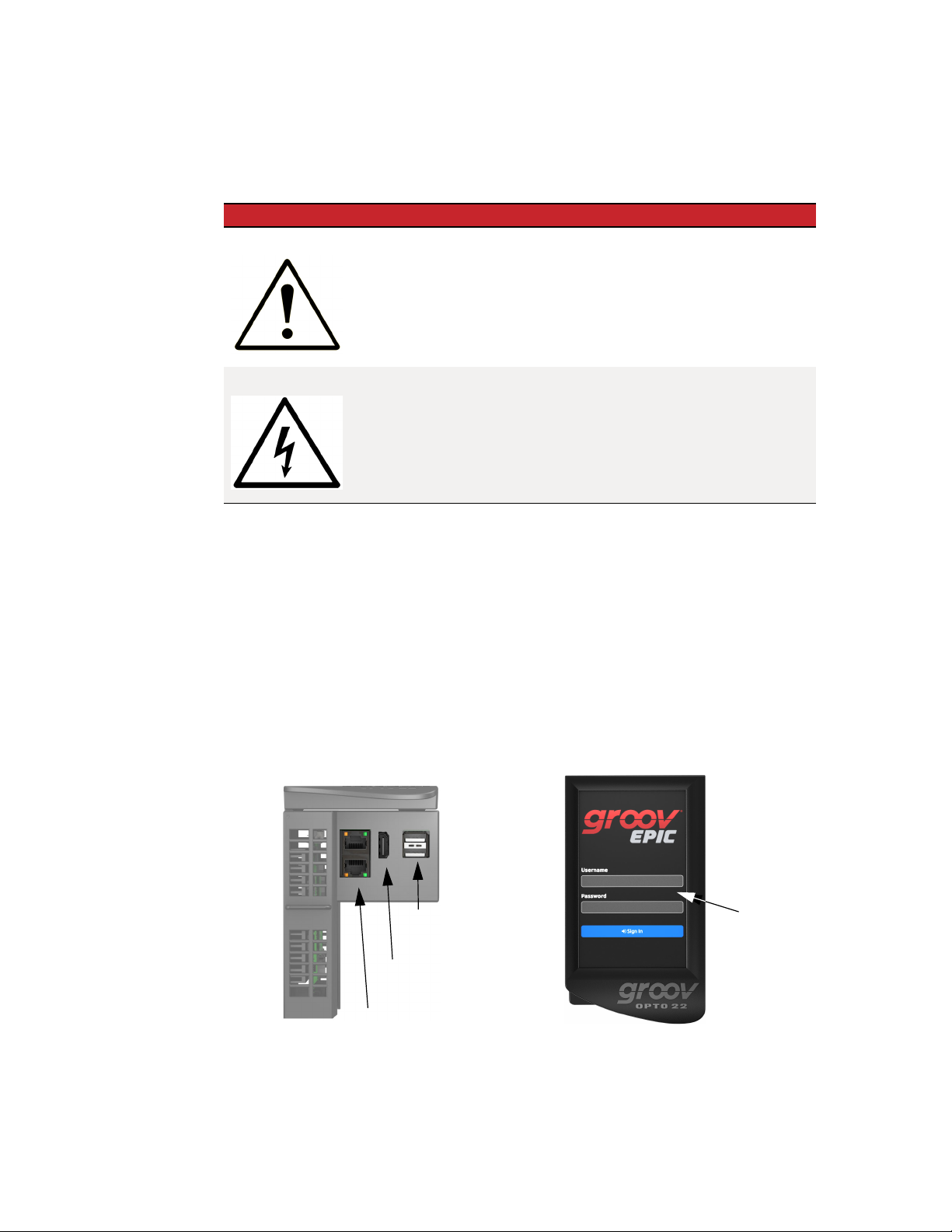
Throughout this guide, you might see two versions of the same page. This is done to show you important
differences between viewing a page through the groov EPIC processor’s touchscreen and viewing the same
page through a computer web browser or mobile device.
groov EPIC touchscreen Computer web browser
groov EPIC User’s Guide
3
Page 18

ABOUT THIS GUIDE
What’s in This Guide
Chapter 1: Welcome to groov EPIC (this chapter) introduces this user’s guide and groov EPIC.
Chapter 2: Additional Safety and Operating Instructions describes important safety and operating
information.
Chapter 3: Assembling your groov EPIC describes how to assemble the parts of a groov EPIC unit (the
processor, the power supply, the chassis, and the I/O modules).
Chapter 4: Initializing the groov EPIC Processor describes the configuration steps you might want to do
first to get your groov EPIC system up and running.
Chapter 5: Navigating Through the groov EPIC Processor describes how to navigate through software on
the groov EPIC processor touchscreen, some differences between navigating on the touchscreen and
navigating through a web browser, and introduces you to some of the important features of some of the
screens, like the Modules page.
Chapter 6: Controlling Access to groov EPIC Processor describes the security features available on the
groov EPIC processor and how you might want to configure these features to control who has access to your
unit.
Chapter 7: Connecting groov EPIC to a Network or Multiple Networks describes the options available to
connect a groov EPIC processor to more complex networking environments.
Chapter 8: Enabling MQTT describes the options available for publishing automation data in a MQTT
infrastructure, as well as what to do to set up these options.
Chapter 9: Configuring System Features describes how to modify features (like networking) so they work
the way you need them to in your application.
Chapter 10: Configure CODESYS and groov EPIC for IEC61131-3 describes how to enable the CODESYS
Runtime Engine so you can build and download applications developed with the CODESYS Development
System.
Chapter 11: Working with groov EPIC Devices in CODESYS Projects describes how to add and configure
a groov EPIC processor to your CODESYS Development System, and how to configure processor parameters
and channel features so you can begin programming.
Chapter 12: Downloading and Running PAC Control Programs describes how to download and run PAC
Control strategies.
Chapter 13: Downloading and Running Custom Control Programs describes how to access the secure
shell feature to develop and download control programs written in other programming languages.
Chapter 14: Developing and Deploying Node-RED flows describes how to get started building and
deploying Node-RED flows, including how to add the Opto 22 nodes.
Chapter 15: Monitoring and Configuring Modules and Channels describes the features available on the
groov EPIC processor to help view the status of your modules and how to configure them.
Chapter 16: Maintaining Your groov EPIC Unit describes the tasks you can do to keep your groov EPIC unit
running in top shape, like applying maintenance. It also describes how to start an OptoSupport Remote
Support Service session.
4
groov EPIC User’s Guide
Chapter 17: Troubleshooting describes what to do when you encounter problems (troubleshooting).
Appendix A: Processor Specifications provides the technical specifications of the groov EPIC processor.
Appendix B: Power Supply Specifications provides the technical specifications of the groov EPIC power
supply, power converter, and power adapter.
Appendix C: Chassis Specifications provides the technical specifications of the groov EPIC chassis.
Page 19

CHAPTER 1: WELCOME TO GROOV EPIC
Appendix D: I/O Module Specifications provides the technical specifications of all the groov I/O modules.
Appendix E: I/O Module Wiring Diagrams provides the wiring diagrams for all the groov I/O modules.
Appendix F: Installing the Correct License describes how to properly install licenses for groov EPIC
processors that have versions of firmware older than 1.3.0.
Appendix G: Advanced Networking Configurations describes special networking functions that are
usually managed by network administrators for specific and rare situations.
groov EPIC User’s Guide
5
Page 20

ABOUT THIS GUIDE
6
groov EPIC User’s Guide
Page 21

Appendix B
2: Additional Safety and Operating Instructions
SAFETY INSTRUCTIONS
Read all the guidelines described in this section before operating or servicing your groov EPIC unit:
• CAUTION: There is a possibility of electric shock. Before accessing any terminals connected to modules
rated as HAZARDOUS LIVE voltage, disconnect or isolate the groov EPIC unit from HAZARDOUS LIVE
voltage.
• Use only Opto 22-provided parts or accessories and in a manner instructed in this guide; do not use
un-authorized parts or accessories. If un-authorized parts or accessories are used on your groov EPIC unit,
the protection provided by the groov EPIC unit may be impaired.
• Use your groov EPIC unit only in a manner in which it complies with all safety and additional instructions
described in this guide. If the groov EPIC unit is used in a manner not specified by Opto 22, the protection
provided by the groov EPIC unit may be impaired.
• The normal environmental conditions for a groov EPIC unit in regards to temperature and humidity are
those conditions that fall within the ranges described in the specifications listed in Appendix A: Processor
Specifications, Appendix B: Power Supply Specifications, Appendix C: Chassis Specifications, and
Appendix D: I/O Module Specifications.
• The groov EPIC unit is to be used indoors or installed in a protective cabinet that provides the conditions
described in Appendix A: Processor Specifications, Appendix B: Power Supply Specifications, Appendix C:
Chassis Specifications, and Appendix D: I/O Module Specifications.
• The groov EPIC unit is rated to withstand transient overvoltages up to the levels of overvoltage
category II.
• The groov EPIC unit is rated to be installed in environments where non-conductive pollution occurs
except where occasionally a temporary conductivity caused by condensation might be expected
(Pollution Degree 2).
• The groov EPIC unit can operate in altitudes of up to 2000 m.
SAFETY INSTRUCTIONS FOR INSTALLING THE groov EPIC UNIT AS PART OF MACHINERY
When you permanently install your groov EPIC unit into another machine, you must attach a power
disconnect device to your groov EPIC unit. The power disconnect device must comply with the following
requirements:
• It must be a switch or a circuit breaker that is easy to reach and operate from the outside of the machine.
• It must disconnect all power lines simultaneously.
• It must be clearly labeled as a power disconnecting device for the controller.
groov EPIC User’s Guide 7
7
Page 22
EXPLANATION OF LABELS OR SYMBOLS
EXPLANATION OF LABELS OR SYMBOLS
The following table explains the labels or symbols you might see on the groov EPIC power supplies, processor,
or modules:
Label or Symbol Explanation
CAUTION: Please consult the user’s guide for additional safety information and
instructions for proper installation, operation, maintenance, and service of this unit.
CAUTION: Possibility of electric shock.
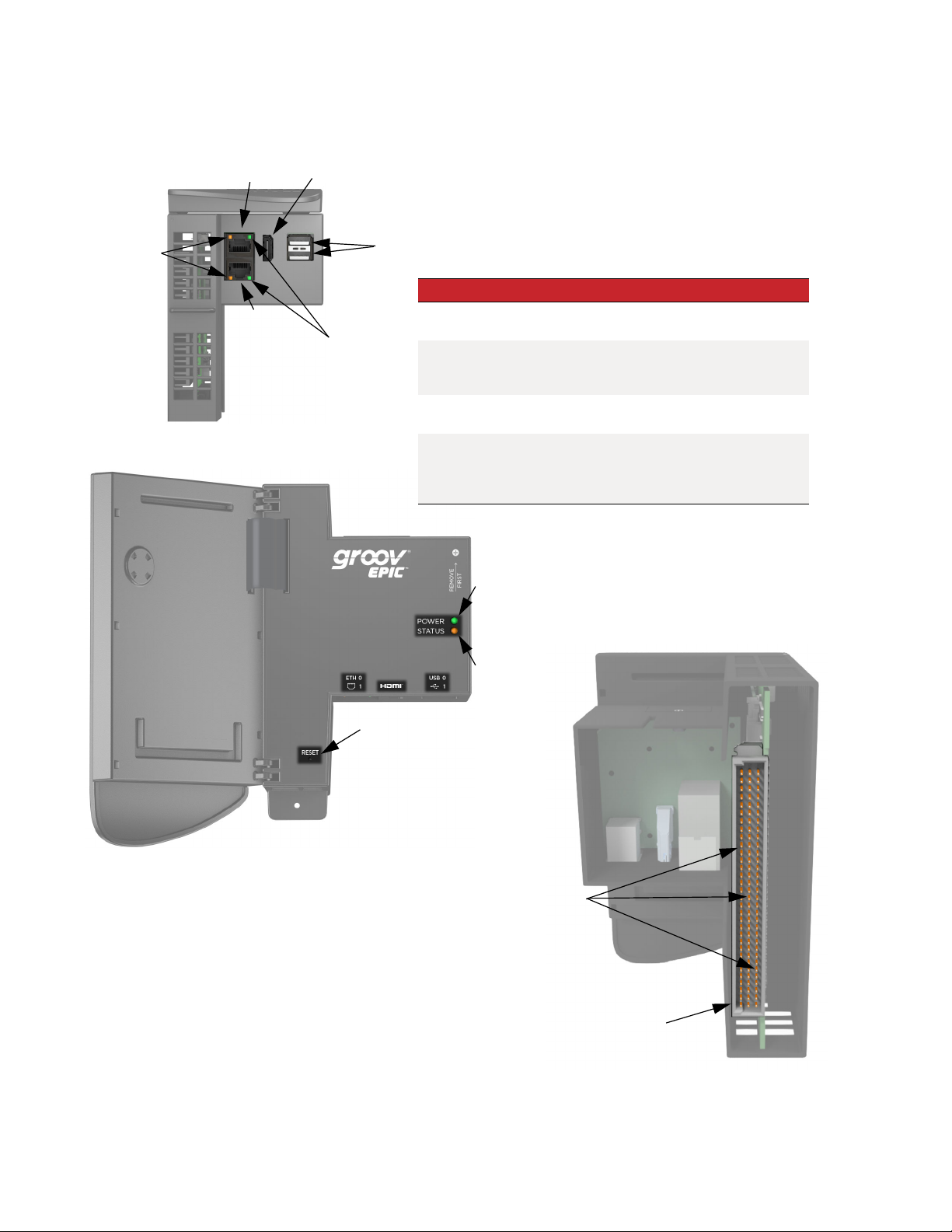
OPERATING CONTROLS
The following diagrams describe the operating controls available on the groov EPIC processor. The bottom
view shows the network interfaces and ports. The front view shows the processor’s touchscreen.
Administrator and operator controls are provided through the touchscreen interface.
• If you log in with a user ID that has administrator level privileges, you can access controls to view and
change settings such as network addresses, channel IDs, or to do some tasks, like restarting the device.
• If you log in with a user ID that has operator level privileges, you can access controls that run the
machinery, equipment, and processes that are controlled and monitored by the control program running
on the groov EPIC processor.
(bottom view)
USB port (2)
HDMI port
Touchscreen
8
groov EPIC User’s Guide
Ethernet Interface (2)
(front view)
Page 23

SERVICE AND MAINTENANCE
To keep your groov EPIC unit up-to-date with the latest software and firmware fixes and features, you’ll want to
regularly check for and apply maintenance to your unit, as described in “Updating Firmware on a groov EPIC
Unit” on page 157.
If you encounter any problems with your groov EPIC unit, follow the instructions in “Collecting Information for
Product Support” on page 165 to collect information before contacting Opto 22 Product Support.
Service (Product Support)
If you are having problems installing or using groov EPIC products and cannot find the help you need in this
guide or on our website, contact Opto 22 Product Support.
CHAPTER 2: ADDITIONAL SAFETY AND OPERATING INSTRUCTIONS
Phone: 800-TEK-OPTO (800-835-6786 toll-free
in the U.S. and Canada)
951-695-3080
Monday through Friday,
7 a.m. to 5 p.m. Pacific Time
Fax: 951-695-3017
Email: support@opto22.com
Opto 22 website: www.opto22.com
NOTE: Email messages and phone calls
to Opto 22 Product Support are
grouped together and answered in the
order received.
groov EPIC User’s Guide
9
Page 24

SERVICE AND MAINTENANCE
10
groov EPIC User’s Guide
Page 25

Appendix C
3: Assembling your groov EPIC
GATHERING YOUR EQUIPMENT AND INFORMATION
Gathering up all the supplies, information, and equipment you need to help you assemble your groov EPIC
unit can make assembling your unit easier:
• A work table and good lighting.
• An accessible power source that complies with the requirements described in Appendix B: Power Supply
Specifications or in the groov EPIC Power Supplies, Converters, and Adapters Data Sheet (form 2246).
• The proper gauge wires to connect the groov EPIC power supply to your power source. For guidance on
selecting the correct wire gauge, see Appendix B: Power Supply Specifications or the groov EPIC Power
Supplies, Converters, and Adapters Data Sheet (form 2246).
• The proper gauge wires to connect your field devices to the I/O modules. For guidance on selecting the
correct wire gauge, see “Connecting field devices to the groov I/O modules” on page 20 or review the
groov I/O module data sheets.
• Pen and paper to note important information that you might need during this process or to keep for
future reference.
• If you are connecting the processor to a network, an Ethernet cable.
• The groov EPIC power supply you selected for your project.
• The groov EPIC chassis you selected for your project. Make sure you have the correct size chassis to hold
the number of modules you are installing.
• The groov I/O modules that you selected for your project.
• The screwdriver that ships with your I/O modules, which helps you connect field device wires to the
terminal connector.
In addition, make sure you have a list of all the I/O channels (sometimes referred to as points) that you need
set up. This might be in a form of a document that maps which channel of which module will connect to a
specific field device/point. If you are working with a terminal strip, review the terminal number assignments,
making sure you understand which terminal numbers are assigned to specific modules and channels.
Any additional information you might need will depend on other factors, like any special configurations for
your network or whether you need to create additional users that have limited access.
After you assemble your unit, you’ll initialize it as described in Chapter 4: Initializing the groov EPIC Processor.
After you finish initializing the unit, it will be ready to run.
FAMILIARIZE YOURSELF WITH THE PROCESSOR AND groov I/O MODULES
Take a few minutes to review the next couple of pages, which show you the different features of the processor and groov I/O modules.
The installation instructions in the documentation rely on these terms to explain how to handle a processor and a module.
groov EPIC User’s Guide 11
11
Page 26
FAMILIARIZE YOURSELF WITH THE PROCESSOR AND GROOV I/O MODULES
groov EPIC Processor
Bottom View:
SPEED LED
Face View:
ETH0
ETH1
HDMI
LINK ACT LED
USB
LED Indicates
SPEED LED
LINK ACT LED
POWER LED
STATUS LED
POWER LED
Indicates link speed (Off = 10 Mbps,
Green = 100 Mbps, Orange = 1000 Mbps)
Indicates link status or activity
(on/solid = link present, blinking = link
present and local activity)
Indicates status of power (Green = on;
Red = on, resetting)
Indicates whether the unit is running with
full functionality. (Green = all normal; blink
green and red = starting a restore to
defaults)
RESET button
Back View:
STATUS LED
Connector Pins
Connector
12
groov EPIC User’s Guide
Page 27
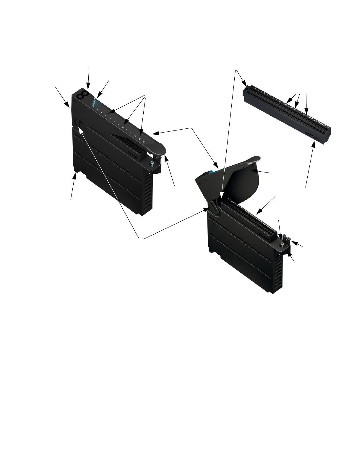
groov I/O Modules
CHAPTER 3: ASSEMBLING YOUR GROOV EPIC
Catch tab
(on the
top of the
module)
Alignment tab (on the
underside of the module)
Touch-sensitive pad
Module LED
Discrete channel indicators
(discrete modules only)
Module cover
Module cover
grip tab
Terminal connector screw
Channels
Wireway
Terminal connector (removable)
Module retention screw
Hinge (2-position)
Module grip tab
To learn what colors the module LED displays, see “Checking Module Status Through the Module LED” on
page 140.
VERIFYING SERIAL NUMBER ON THE PROCESSOR
When you unpack your groov EPIC processor, open the LCD display and verify that you can find the serial
number on the label attached to the back of the LCD display.
ACTIVATING THE groov EPIC UNIT AND DOWNLOADING THE LICENSE FILE
Each groov EPIC processor comes with an activation code, which helps you obtain your license file.
1. Make a note of the serial number of your groov EPIC processor, which is on a label attached to the back of
the LCD display.
2. On a computer or mobile device connected to the Internet, go to manage.groov.com.
Strain relief tab
groov EPIC User’s Guide
13
Page 28
ASSEMBLING YOUR UNIT
3. Follow the directions for activating your groov EPIC processor and obtaining a license file.
4. Save the license file onto your computer or mobile device and remember where you saved it. You’ll need
that information when you initialize your groov EPIC unit, as described in Chapter 4: Initializing the groov
EPIC Processor.
ASSEMBLING YOUR UNIT
After you complete the steps in this section, you will have mounted the power supply, the processor, and the
I/O modules on to the chassis. In the section that follows, you’ll wire the I/O modules to field devices, and the
power supply to the power source.
CAUTION: For electrical safety, do not turn on the power supply. Make sure to de-energize field devices wired
to the module terminal connectors before proceeding with these steps.
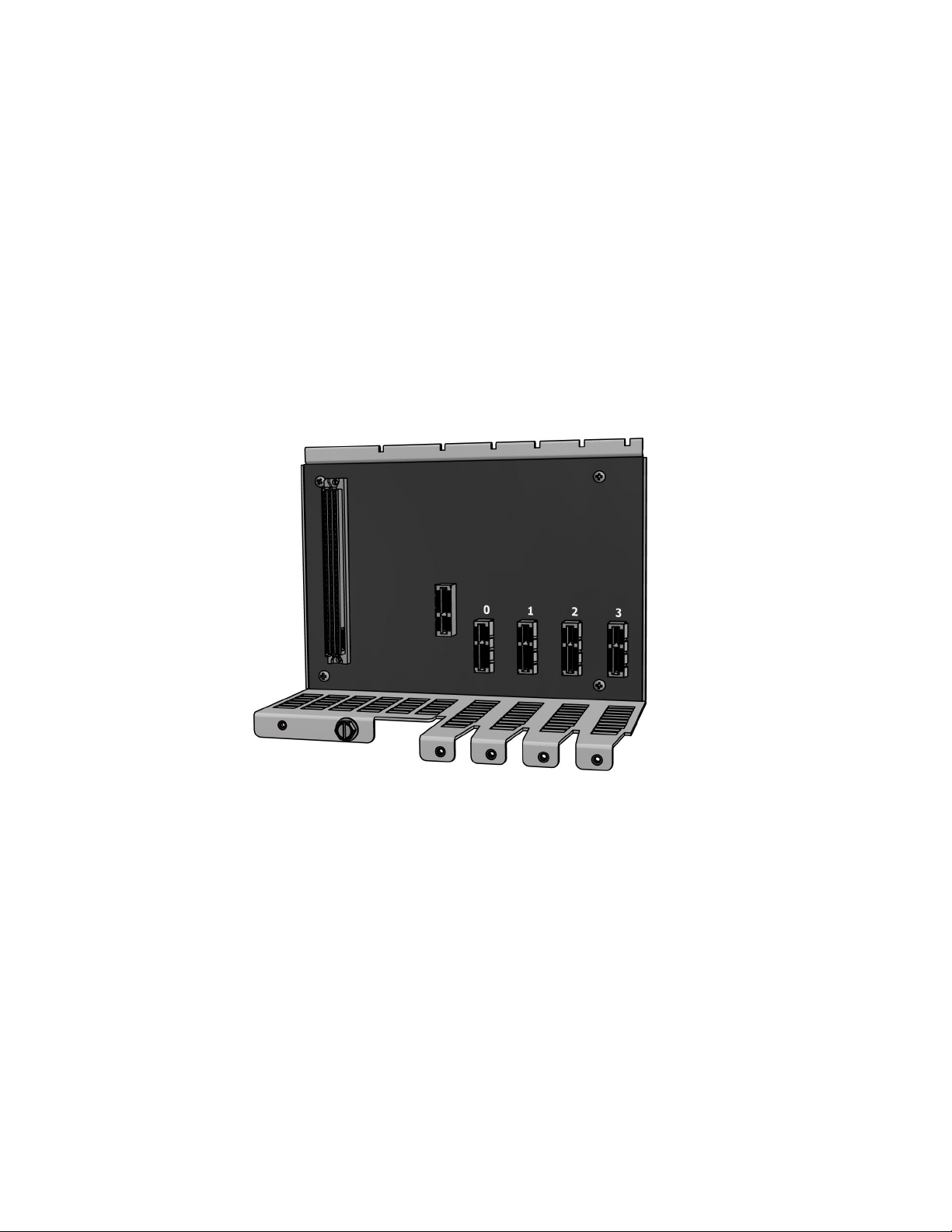
1. Orient the groov EPIC chassis so that the module connector numbers are right-side up, with zero on the
left, as shown in the diagram below.
14
2. Install the power supply:
a. Hold the power supply at a 45° angle, with the tabs at the back of the supply aligned with the
notches on the chassis.
groov EPIC User’s Guide
Page 29
CHAPTER 3: ASSEMBLING YOUR GROOV EPIC
b. Lower the front-end of the supply onto the chassis until you feel the plug snap into the slot.
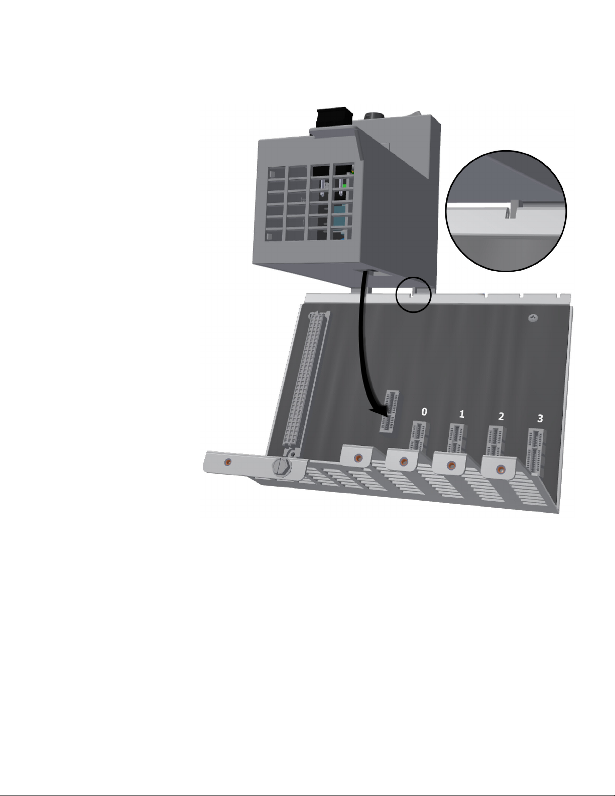
3. Install the processor:
groov EPIC User’s Guide
15
Page 30

ASSEMBLING YOUR UNIT
a. Lift the LCD display so you can see the notch on the processor.
Notch
b. Hold the processor by the left side, and make sure that the notch on the processor aligns with the
guide tab on the power supply.
16
c. Align and then seat the processor:
groov EPIC User’s Guide
Page 31

CHAPTER 3: ASSEMBLING YOUR GROOV EPIC
– Align the processor. With the LCD display open, slowly guide the processor straight onto the
chassis—holding it flush against the side of the power supply—until you feel the processor
start to touch the connector on the chassis.
When it touches, lightly jiggle the processor to help the pins on the processor’s connector
properly align themselves into the holes of the chassis’ connector.
– Seat the processor. Push the processor (not the LCD display) into the connector until it resists
further pressure.
groov EPIC User’s Guide
17
Page 32

ASSEMBLING YOUR UNIT
IMPORTANT: Do not push on the LCD display.
d. Tighten the retention screws that attach the processor to the power supply and the chassis to the
recommended torque listed in Appendix A: Processor Specifications.
Retention screws
e. Close the LCD display.
4. Install the modules:
a. Hold the module at a 45° angle, lining up the alignment tab on the back tip of the module with the
slot at the back of the chassis.
18
groov EPIC User’s Guide
Page 33

CHAPTER 3: ASSEMBLING YOUR GROOV EPIC
b. Pivot the front of the module down to the module connector on the chassis. Push to snap the
module into the connector.
c. Swing the module cover up so you can access the module hold-down screw. Secure the module
into position by tightening the module hold-down screw.
groov EPIC User’s Guide
19
Page 34

CONNECTING POWER SUPPLY WIRES AND FIELD DEVICE WIRES
CAUTION: Do not over-tighten. See the torque specs inAppendix D: I/O Module Specifications.
Hold-down screw
CONNECTING POWER SUPPLY WIRES AND FIELD DEVICE WIRES
After you complete the steps in this section, you will turn on you groov EPIC unit and move on to initializing
the unit.
Connecting field devices to the groov I/O modules
Before you begin wiring, do the following tasks:
• Select the appropriate wire. The terminal connectors are rated for 28–14 AWG wire. If you’re using
stranded wire, tin the strands for an easier, better connection.
• Ensure that you have the screwdriver supplied with your module.
• If you are unfamiliar with the names of some of the parts of the module, review the diagrams on the
following page and in “Familiarize yourself with the Processor and groov I/O modules” on page 11.
• It may be easier to insert wires if you remove the terminal connector from the module. To remove the
terminal connector, loosen the terminal connector screw at one end of the connector, then pull the
connector up to remove it from the module.
• If you have never used a spring-clamp wiring system, take a moment to familiarize yourself with the
diagram on the following page. The clamp release hole is where you will insert the screwdriver. The field
wiring hole is where you will insert your field wires. If you look into the field wiring hole, you will see a
highly reflective surface. If you can see that surface, that means that the clamp is closed.
20
groov EPIC User’s Guide
Page 35

CHAPTER 3: ASSEMBLING YOUR GROOV EPIC
In this example, pin 3’s clamp release hole and corresponding field
wiring hole are open.
Terminal connector screw
Pin numbers
Field wiring holes
Clamp release holes
Follow these instructions to connect your field wires to the module:
1. Orient the module or terminal connector to match the wiring diagrams, which are listed on Appendix E:
I/O Module Wiring Diagrams. To make it easier to handle the screwdriver and the field wires, secure the
module by doing one of the following:
– If you are working with the terminal connector while it is attached to the module, make sure the
module is screwed securely to the chassis.
– If you are working only with the terminal connector, secure the terminal connector with a clamp.
2. Hold the screwdriver so that you can place the flat side of the blade against the left side of the clamp
release hole.
3. Slide the screwdriver into the clamp release hole, along the left side, until you feel the blade begin to
meet some resistance. Gently push the screwdriver in a little more, until you feel the screwdriver stop.
Note: If you push in too hard, the screwdriver might pop out of the clamp release hole and you’ll have to return
to step 2.
– Look into the field wiring hole. If it is dark, the clamp is open. You can go to the next step.
– If you can still see the highly reflective surface, gently pull the screwdriver handle to the left until you
feel the blade stop. Hold the screwdriver in that position. Look into the field wiring hole. If it is dark,
the clamp is open. You can go to the next step.
4. Insert the wire into the field wiring hole until it meets complete resistance. Then pull out the screwdriver.
5. Test that the wire is secure by gently pulling on it. If the wire pulls out, repeat steps 2 through 4.
To remove a wire, push the screwdriver into the clamp release hole as described in steps 2 and 3 above, and
then pull the wire out.
groov EPIC User’s Guide
21
Page 36

CONNECTING POWER SUPPLY WIRES AND FIELD DEVICE WIRES
Connecting ground
Connect a ground strap to the ground lug on the chassis. The ground lug is colored green on the chassis to
make it easier to identify.
Connecting power supply wires
Here are a few guidelines to review before connecting your power supply wires:
Always use a separate field supply
Ground Lug
Use a separate power supply for the field side of the I/O. Using the chassis supply for field actuation and
monitoring defeats the isolation the I/O modules offer and therefore increases the chance of a ground loop
within the control system. Additionally, fluctuations on the field side can cause undesirable voltage
fluctuations that may interfere with the processor’s operation.
Some modules (for example, the GRV-OVMALC-8) provide their own isolated, regulated, field-side power
supply.
Power wiring guidelines
Opto 22 recommends you follow these wiring guidelines:
• Use a mains-isolated 24 to 48 VDC power source or supply to feed the GRV-EPIC-PSDC.
• Use the appropriate gage wire:
– For GRV-EPIC-PSDC or GRV-EPIC-PSPT with DC input, use 16 to 12 AWG. Keep the wires as short as
possible.
– For GRV-EPIC-PSAC, use 18 to 12 AWG . Keep the wires as short as possible.
Power wiring diagrams
Before wiring the GRV-EPIC-PSAC, GRV-EPIC-PSDC or GRV-EPIC-PSPT, verify that your wiring cables conform to
the requirements described previously.
22
groov EPIC User’s Guide
Page 37

CHAPTER 3: ASSEMBLING YOUR GROOV EPIC
GRV-EPIC-PSAC
CONNECTING THE ETHERNET CABLE
If the LCD display is closed, lift it so you can more easily access the Ethernet network interfaces. Connect your
Ethernet cable to the network interface labeled ETH0.
GRV-EPIC-PSDC, GRV-EPIC-PSPT
TURN ON UNIT AND CONTINUE WITH INITIALIZING THE UNIT
If the LCD display is closed, lift it so you can access the power switch. Flip the power switch and then close the
LCD display. The LCD display shows you the progress of the processor’s start-up sequence. When you see the
“Welcome!” screen, you are ready to initialize your groov EPIC unit. For important instructions about initializing
your unit, see Chapter 4: Initializing the groov EPIC Processor.
groov EPIC User’s Guide
23
Page 38

TURN ON UNIT AND CONTINUE WITH INITIALIZING THE UNIT
24
groov EPIC User’s Guide
Page 39

4: Initializing the groov EPIC Processor
After you assemble your groov EPIC unit and turn it on, the groov EPIC
processor runs through its start-up sequence and then displays the
Welcome! screen, shown to the right. If the Eth0 IP Address box does not
show an IP address, see “Ethernet Cable is Plugged In, but No IP Address” on
page 171.
If the Eth0 IP Address box shows an IP address, try connecting to that IP
address with a web browser by typing https://<ip address> in the
browser’s URL bar. The browser displays the same Welcome! screen, shown
below. If the Welcome! screen does not appear in the browser, see “Web
Browser Can’t Connect to Processor” on page 171.
groov EPIC touchscreen
Before you click or tap on Let’s get started! ( ), make sure you have the following information and
supplies:
• Your license file. If you don’t have one, you can get one by following the instructions in “Activating the
groov EPIC unit and downloading the license file” on page 13.
• A computer or mobile device connected to the Internet.
• A hostname for your processor. You may want to consult with your network administrator for guidance
on selecting a hostname.
• A user name and password that follows strong security recommendations. This username and
• password is the first administrator level user for your Learning Center. Remember it! groov EPIC does not
provide a way to recover a lost password or username.
groov EPIC User’s Guide 25
25
Page 40

CREATING THE FIRST ADMINISTRATOR ACCOUNT
• Pen and paper to note important information that you might need during this process or to keep for
future reference.
If this is the first time you navigate through a controller with a touchscreen or you are new to the groov EPIC
processor, you might want to read through Chapter 5: Navigating Through the groov EPIC Processor to
become familiar with how to operate it and how it behaves.
You may also want to make note of the information shown in the lower-half of the Welcome! screen:
• You want the firmware version number so that you can compare it to the firmware updates available on
the Opto 22 web site. If the firmware on the web site is newer than the one installed on the processor,
you may want to apply the new firmware after you finish initializing the groov EPIC processor.
• If the Eth0 IP Address box displays an IP address and you were able to connect to it through a browser,
you can finish the steps in this chapter by navigating through the web browser with a mouse and
entering data with the keyboard.
CREATING THE FIRST ADMINISTRATOR ACCOUNT
Click or tap on Let’s get started! ( ). You’ll see the Create an Account screen, shown below.
groov EPIC touchscreen
Read the information in the warning box. This first administrator account is very important because it provides
administrator privileges over the groov EPIC processor, which gives you access to all the functions you need to
configure the processor, maintain it, and create other accounts.
Computer web browser
26
It’s also important to remember the password to this account. The groov EPIC processor does not provide a
way to recover this password nor an alternate way to access this account if you forget the password. Also,
Opto 22 cannot recover this password or provide access to the account.
It is a good idea to follow best practices regarding passwords (for example, mixing cases and including
numbers) when you create your password. Your password must be a minimum of 1 character and can be a
maximum of 128 characters.
After you type in the user ID and password, click or tap on Create Account.
groov EPIC User’s Guide
Page 41

CHAPTER 4: INITIALIZING THE GROOV EPIC PROCESSOR
CHOOSING BETWEEN QUICK START AND CONFIGURE DEVICE
After you create an account, the groov EPIC processor displays the screen below.
• Quick Start. The quick start provides a list of suggested configuration steps that you should complete first
to get your groov EPIC system up and running. You may want to choose this option if this is the first time
you configure a groov EPIC unit.
• Configure Device. If you select this option, the groov EPIC processor displays the main groov Manage
page, where you can make any configuration changes. You may want to choose this option if you have
configured a groov EPIC processor before or you feel confident you have all the information and
understand the technology and software installed on the processor to complete any configuration steps.
If you choose to run Quick Start, the rest of this chapter can help you make additional decisions about the
initial configuration steps. If you choose Configure Device, you can skip the rest of this chapter and configure
your groov EPIC processor, referring to the rest of the user’s guide for additional information.
groov EPIC User’s Guide
27
Page 42

COMPLETING THE QUICK START
COMPLETING THE QUICK START
When you click or tap Quick Start ( ), the groov EPIC processor displays the page below.
groov EPIC touchscreen
The boxes are organized to suggest an order in which to complete the configuration. However, you do not
have to follow this order nor do a configuration task for every box. Here’s why you might want to complete
each step:
• Networking. You might want to configure or change networking settings because:
• License. Your groov View license comes with the purchase of the groov EPIC processor. If you ordered
• Accounts. You might want to create additional accounts as required by the design of your control
• Display. You might want to calibrate the groov EPIC processor’s touchscreen to ensure smooth operation.
• Time. You can choose between manually setting the date and time, selecting a time zone from a list, or
Computer web browser
– You noticed that the Eth0 IP address box displayed the message Not Available and you want to set
the IP addresses manually or configure settings so that the processor can connect to a DHCP server
and obtain an IP address automatically.
– You want to change the IP address that was assigned to the processor. You might want to connect
to a specific DHCP server or set the IP address manually (which would make it a static IP address).
some of the optional licenses (for example, GROOV-LIC-EDGE) and you have that license file handy, you
can also upload it. You’ll need to do this step on a computer or mobile device; you can’t upload licenses
through the groov EPIC processor’s touchscreen.
program and HMI.
If you want to connect an external monitor, you might want to connect it through the HDMI port and
configure it at this time.
selecting a time server that will synchronize your processor’s date and time with that time server’s date
and time.
28
After you complete these initial configuration steps, you should check whether you have the latest firmware
installed on your groov EPIC processor. If you do, you can continue on to more advanced configuration or
begin to download and run a strategy or other control program.
groov EPIC User’s Guide
Page 43

5: Navigating Through the groov EPIC Processor
You navigate through the groov EPIC processor touchscreen in much the same way you navigate through a
smart phone or tablet. You can tap on navigation aids, swipe up or down to see more information, or swipe
right to return to a previous page. The touchscreen responds to the touch of a finger or a stylus, although it
might require a slightly stronger push or slide than a typical smart phone or tablet. When you connect an
external touchscreen monitor to the processor, you navigate in the same manner as if you were touching the
processor touchscreen.
The groov modules include a touch-sensitive pad. When you place your finger on the touch-sensitive pad of a
module for more than two seconds, groov Manage displays information about that module on the
touchscreen. The following diagram shows what the groov EPIC processor displays on the touchscreen after
you touch the touch-sensitive pad of a module (GRV-IAC-24) mounted on slot 1, and then tap on the Info tab.
Press the touch-sensitive pad for 2 seconds. The groov EPIC
processor displays that module’s information. Tap on the
Info tab to see the wiring diagram.
When you connect to the processor through a web browser on a computer, you navigate through the web
browser in much the same way you navigate through any other web application on your computer. You can
click on navigation aides like the navigation bar or links, and scroll up and down with a mouse.
CLICK OR TAP YOUR WAY AROUND groov MANAGE
After you configure your groov EPIC processor with an IP address, you can connect to the processor through a
web browser with that IP address. When you connect through a web browser, the processor displays the login
groov EPIC User’s Guide 29
29
Page 44

LEARNING THE SCREEN NAVIGATION AIDS
page. If you enter a user ID with administrator privileges, the processor displays groov Manage. You can
navigate through groov Manage in much the same way you navigate through any web application.
Because you can access the processor through a browser or through the processor’s touchscreen, the
directions in this guide are written with both methods in mind. So, you may notice that instructions include
the phrase “Click or tap”: ”click” as a reference to clicking with a mouse on a computer screen, “tap” to indicate
touching the processor’s touchscreen with your finger or a stylus.
LEARNING THE SCREEN NAVIGATION AIDS
The diagram below shows some of the differences and similarities between pages when you look at them
through the groov EPIC processor or a web browser (either on a computer or a mobile device). The diagram
also identifies some of the important navigation aids, which are described on the following page:
groov EPIC touchscreen
Computer web browser
A
B
C
D
30
E
groov EPIC User’s Guide
Page 45

CHAPTER 5: NAVIGATING THROUGH THE GROOV EPIC PROCESSOR
A Menu button ( ). Click or tap on this button to access a list of frequently visited pages. This button
can help you quickly jump to these pages.
B Cancel or previous page. The upper-left area of the screen provides a way to cancel any changes you
might have made to a page, to return to the previous page, or both.
C Save or Configure. If there are settings on the page that you can change, the upper-right area of the
page displays the word Configure. Click on Configure to open up the page where you actually make
the changes.
If this area shows the word Save, you must click on it to save any changes you made to settings on
the page. If, after saving, the processor must restart an application or service, it displays a message to
let you know.
If this area is blank, that means you can’t make any changes to this page.
D Tabs. A method of grouping information related to one object into different categories. For example,
information related to a module is divided into three categories: Channels, Info (specification
information), and Config (module-specific information, like serial number). Each of these categories
is in its own tab.
E Links. When you see these arrows, it indicates that clicking or tapping on the arrow will open another
page that displays more information and provides more functions related to the item. For example,
when you click or tap on Project Management in the Node-RED page, the processor displays another
page with information and functions to help you manage a Node-RED project.
There is a small difference you might notice with links, depending on whether you are viewing a
groov Manage page through the groov EPIC processor’s touchscreen or a web browser. In a web
browser, you can click on any area along the same row where the link is located to navigate through
that link. In the groov EPIC touchscreen, you must tap on the arrow to navigate through that link.
NAVIGATING THROUGH groov MANAGE
At the top of the groov Manage page is a navigation bar that always remains visible as you navigate through
the screens. This navigation bar contains a menu button ( ) that gives you quick access to the most
frequently visited screens of groov Manage:
Navigation bar, with the menu
button closed.
• Home, the main page of groov Manage.
• I/O, the page that displays a visual representation of the chassis, indicating which slots have modules
mounted on them, what type of modules are mounted on those slots, and the status of the modules.
• Controller, the page that guides you to either the PAC Control Engine page or the CODESYS Runtime
Engine page. From either of those two pages, you can access several features, including:
– Viewing the status of the engine.
– Viewing the name of the strategy or applications running on the processor.
– Disabling or enabling the engine.
Navigation bar, with the menu button
open.
groov EPIC User’s Guide
31
Page 46

NAVIGATING THROUGH GROOV MANAGE
• System, the page that displays functions to help you configure system-level settings, like network
settings, display settings (for the touchscreen and external monitors), time zone settings, licenses, and
the ability to restart the processor.
• Info and Help, the page that displays functions to help you learn more information about the processor,
like system logs, current system up-time information, firmware versions, as well as a way to access the
Quick Start feature.
• User, the page that displays the user name of the current user and the fields to change the current user’s
password.
Navigating Through groov Manage on the groov EPIC Processor Touchscreen
Some screens contain more information than can fit in the display. Remember to slide your finger or stylus up
and down on the screen to view more information.
While navigating through the screens on the groov EPIC processor touchscreen, in addition to tapping on
buttons or other navigation aids, you can swipe your finger or stylus across the screen from left to right to
return to a previous page.
The following example shows how to navigate through a set of screens by either swiping or tapping the
buttons on the screen:
4.
3.
1. 2.
1. Starting from the Home page, tap on System ( ) to open the System page.
2. Tap on Time ( ) to open the Time Settings page.
3. To go from the Time Settings page back to the System page, tap on System near the top left corner or
swipe your finger on the screen from left to right.
4. To go from the System page to the Home page, tap on Home near the top left corner or swipe your finger
from left to right.
As a quick alternative, you can go from the Time Settings page to the Home page by tapping on the menu
button ( ), then tapping on Home.
32
Whenever you change settings, remember to press Save (usually at the top right corner of screen) to save your
changes. If you don’t want to save your changes, press Cancel (usually at the top left corner of the screen) or
swipe from left to right. Some changes might require a restart of the processor or a service; the processor will
notify you of these instances.
groov EPIC User’s Guide
Page 47

CHAPTER 5: NAVIGATING THROUGH THE GROOV EPIC PROCESSOR
There are some functions that can only be done through a computer or mobile device. When that happens,
the processor’s touchscreen displays a message like the following:
Navigating Through groov Manage on a Computer or Mobile Device
You can navigate through groov Manage on a computer or mobile device in much the same way you navigate
through any other web application. There are some differences, however:
• Drag-and-drop—This is a feature commonly used on a computer to visually and easily move files from
one location to another. You can drag-and-drop files into the groov EPIC processor on any groov Manage
page with an upload button.
• Editors—You can’t build Node-RED flows or groov View HMIs through the processor’s touchscreen.
That’s why, on some pages, you’ll see buttons or options when you are on a computer that you can’t see
when you are on the processor’s touchscreen. For example, on the Node-RED page, you won’t see the
Open Node-RED Editor button when you are on the processor’s touchscreen:
Computer web browsergroov EPIC touchscreen
groov EPIC User’s Guide
33
Page 48

FINDING INFORMATION ABOUT I/O MODULES AND THEIR CHANNELS
FINDING INFORMATION ABOUT I/O MODULES AND THEIR CHANNELS
To view information about and making changes to I/O modules and their channels is through the Modules
page of groov Manage. To reach that page, log into your groov EPIC processor with a user ID that has
administrator privileges and then do any of the following:
• Click or tap on the menu button ( ), then select I/O.
• In the Home page, click or tap on I/O ( ).
Either action displays the Modules page. The page displays an image that simulates the chassis and the I/O
modules mounted on the chassis, along with colors that match the color shown by the module LED. The
following diagram displays a 16-module chassis with 9 modules mounted on the chassis in slots 0, 4, 5, 7, 9,
11, 13, 14, and 15. All modules are operating normally, which is indicated by the blue color on the right of each
box that represents a mounted module.
34
Each box represents a slot on the chassis. If the box is gray and shows the word “Empty”, that means no
module is installed in that slot on the chassis. If the box is black, that means a module is installed in that slot
on the chassis. The following diagram explains the information displayed in the black boxes:
Numbers represent the
module connector number
(slot) on the chassis.
The part number of the groov module, without the GRV- prefix. In
this diagram, a GRV-IAC-24, GRV-IDCI-12, GRV-ODCI-12 and a
GRV-IACI-12 module are installed on the chassis.
groov EPIC User’s Guide
Two-digit code indicating module type:
• First digit: A for Analog, D for digital
• Second digit: I for input, O for output
The vertical bar represents the module LED.
The color matches the current color being
shown on the module LED.
Page 49

CHAPTER 5: NAVIGATING THROUGH THE GROOV EPIC PROCESSOR
You can click or tap on a black box to show current information about that module. For example, if you click or
tap on module 3 ( ), the groov Manage displays the following page:
groov EPIC touchscreen
The three tabs display the following information:
• The Channels tab lists the channels on the module, displays the status of each channel, and provides a
link to the configuration page for each channel. In the configuration page, you can change the name of
the channel, get more information about a quality error, or change options that are specific to each
module.
• The Info tab shows you information about the module, like the wiring diagram, the specification
information, and firmware version.
• The Config tab, when you view it through a computer or mobile device, provides a way for you to upload
new firmware to the module.
Computer web browser
groov EPIC User’s Guide
35
Page 50

FINDING INFORMATION ABOUT I/O MODULES AND THEIR CHANNELS
36
groov EPIC User’s Guide
Page 51

6: Controlling Access to groov EPIC Processor
PART OF AN OVERALL SECURITY SYSTEM
When you control access to the groov EPIC processor, consider it as part of a total security system that includes
other best practices you might want to implement; for example, requiring that authorized users change their
passwords every three months or securing the control equipment in a locked cabinet with keys accessible to a
limited number of personnel.
The groov EPIC Security Design and Best Practices Technical Note (form 2310) describes some of the security
features designed into the groov EPIC processor. Review this technical note carefully and coordinate with your
IT department to determine which security features provided by the groov EPIC processor will work best with
your application and network.
IMPORTANT: groov Manage does not provide timeout-based logout. You must implement the important
practice of always logging out of any ID that has administrator privileges to prevent unauthorized access to the
processor.
CREATING USER IDS AND CONFIGURING THEIR ACCESS
With groov Manage, you can create user IDs and limit access to functionality, features, or even HMIs. Before you
create a user ID, consider the following questions:
• How many users do you want to create?
• What functions do you want the users to access?
• How will you secure (encrypt or password-protect) the information about the users?
Choosing Access Levels for Users
The following information can help you determine what access to give a user and what level of access to give
a user for a particular service or feature:
• A system-wide administrator can do the following:
– Create other user accounts
– Access all applications and services running on this processor
– Change the passwords of other accounts
– Sign out any and all users currently logged into this processor
– Disable the control engine
– Change system-level settings like network, I/O, display, time and date, etc.
• groov Manage
groov EPIC User’s Guide 37
37
Page 52

MANAGING THE SSL SECURITY FEATURES OF YOUR GROOV EPIC PROCESSOR
groov Manage is an administrator-level function, so if the user is a system-wide administrator, they have
access to groov Manage. If the user is not a system-wide administrator, they do not have access to groov
Manage.
• groov View
There are several levels of access to groov View. These levels are available only if the user is not a
system-wide administrator.
– Editor
– Operator
– Kiosk
– None
A system-wide administrator has administrator access to groov View, which means that they can switch
to groov View and, when connected to the processor through a web browser, switch to build mode to
build groov View HMIs.
• Node-RED
Access to Node-RED is either Editor or Off. For system-wide administrators, Editor is the automatic and
only access level. For all other users, you can set the access level to either Editor or Off.
• PAC REST API
Access to the PAC REST APIs can be one of the following:
– Read-Write
– Read-Only
– None
Creating User IDs
After you consider what types of users you want to create and what they will have access to, do the following:
1. Log into your groov EPIC processor with a user ID that has administrator privileges.
2. Click or tap Accounts ( ).
3. Click or tap Add (in the upper right corner).
4. Type in the required information and select the permissions you want that user to have.
5. Click or tap Save (in the upper right corner).
Repeat these steps for every user account you want to create.
MANAGING THE SSL SECURITY FEATURES OF YOUR groov EPIC PROCESSOR
The SSL security features on the groov EPIC processor help you establish secure communication between the
groov EPIC processor and web browsers, servers, brokers, and cloud services.
Learning How SSL Works on groov EPIC
If you are not familiar with SSL, you might want to spend some time reading the following OptoBlog,
Understanding SSL/TLS and HTTPS.
Each groov EPIC processor comes with a unique certificate (called a self-signed, server SSL certificate) to
enable communication between its internal web applications (like groov Manage, groov View, and Node-RED)
and web browsers on computers and mobile devices. When you connect to the groov EPIC processor through
a web browser for the first time, the browser will display a warning message that the site (in this case, the
groov EPIC processor) is untrusted. To avoid the warning, you can install the self-signed, server SSL certificate
into the certificate store of the web browser. Afterwards, the browser will “trust” your processor (the site) and
no longer display that warning.
38
groov EPIC User’s Guide
Page 53

CHAPTER 6: CONTROLLING ACCESS TO GROOV EPIC PROCESSOR
Why Change the SSL Security Features on Your groov EPIC Processor?
A self-signed certificate is useful for network situations with few users, limited accessibility, or limited scope.
For example, an internal test lab where the groov EPIC processor communicates only to one computer or
when you are developing your control application so that you can conduct testing in your own closed control
network.
However, you might want to change the SSL security features on your groov EPIC processor for any of the
following situations:
• You want to allow access to the processor by many more users and through many devices (like
computers, smartphones, and tablets).
• You want to allow access to the processor by servers, brokers, and cloud services, like MQTT with
Sparkplug or Node-RED.
• You want to allow communication to travel through the Internet.
In these situations, you might want to switch to using a CA-signed certificate, where CA means “Certificate
Authority”. A Certificate Authority is an organization which vouches for your groov EPIC processor’s identity.
CA-signed certificates relieve you of the work of installing the certificate on the countless number of web
browsers, servers, brokers, and cloud services that might want to connect to your processor. When the
CA-signed certificate is installed on the groov EPIC processor and devices that access the processor, the
certificate validates the connection between the user and the processor. So long as you stay connected
directly to the groov EPIC processor on a secure connection (using https), you are protected from a
man-in-the-middle attack.
Creating a Self-Signed Certificate
1. On a computer or mobile device, log into your groov EPIC processor with a user ID that has administrator
privileges.
2. Click Security ( ).
3. Click Server SSL ( ).
4. Click Create Certificate ( ).
5. In the Create Certificate page, enter the information requested.
Server Name—Enter the fully qualified domain name or IP address of this groov EPIC processor that
client browsers will use to access it. The server name may contain letters a–z (case insensitive), digits 0–9,
or a hyphen (-). No other characters are allowed. The server name must not start with a hyphen.
Example:
If the URL you will use to access the processor in client browsers is https://process1.acme.com, then type
in process1.acme.com
Example:
If the URL that the client browsers will use to access the processor is https://mobilehmi.mydomain.com,
then type in mobilehmi.mydomain.com
Email—The email address of the individual in your organization requesting the certificate and who
would be responsible for responding to any inquiries about this certificate.
Department—Information to differentiate between divisions within an organization. For example,
“Engineering” or “IT”. If applicable, you can enter the DBA (doing business as) name in this field.
Organization—The legally registered name of your business. The listed organization must be the legal
registrant of the domain name in the certificate request. If you are enrolling as a small business or sole
proprietor, please enter the certificate requester’s name in this field, and the DBA (doing business as)
name in the Organizational Unit field.
City or Locality—Name of the city or locality where your organization is located. Please spell out the
name of the city or locality. Do not abbreviate.
groov EPIC User’s Guide
39
Page 54

MANAGING THE SSL SECURITY FEATURES OF YOUR GROOV EPIC PROCESSOR
State—Name of state, province, region, territory where your organization is located. Please enter the full
name. Do not abbreviate.
Country Code—The two-letter International Organization for Standardization (ISO-) format country
code for the country in which your organization is legally registered. See
http://www.digicert.com/ssl-certificate-country-codes.htm for a list of codes. For example, the code for
the United States is US.
Days until expiration—Enter the number of days before the certificate is expired and has to be
replaced. Opto 22 recommends 3560 (10 years).
RSA key size—Enter the size of the RSA key. The default size of 2048 is a generally recommended value.
Higher values will take longer to create.
6. Click Create. groov Manage immediately installs the new private key and certificate, and then restarts
groov Manage.
The processor now has new copies of the Public Certificate, Private key, and CSR , which you can download
when you need to request a CA-signed certificate.
Switching to a CA-signed Certificate
When you switch to a CA-signed certificate, consider the following:
• The cost of a certificate from a certificate authority ranges from free to $300 or more, depending on the
features and company you buy them from. Please work with your IT department before you begin this
task.
• You will send the CSR to the certificate authority of your choice. The certificate authority verifies the
identification information and signs the CSR, which then becomes a CA-signed certificate. That’s why it is
important that you enter accurate information in step 5 of “Creating a Self-Signed Certificate” on page 39.
If you have not created a self-signed certificate, do that first. See “Creating a Self-Signed Certificate” on
page 39.
1. On a computer or mobile device, log into your groov EPIC processor with a user ID that has administrator
privileges.
2. Click Security.
3. Click Server SSL.
4. Click Download CSR.
5. Navigate to a folder where you want to store the CSR file. Make a note of the file name and path to the
folder. Click Save.
6. Go to the certificate authority (most likely a web site) and provide them with the information they
request in whatever format they request.
When filling out a form for a CA-signed certificate, keep in mind that an SSL certificate works with any
operating system. If you are asked to select an operating system, select “other” if it an option. It’s OK to
select a specific operating system, if necessary.
7. Finish the transaction with the certificate authority and receive your new SSL certificate.
8. Upload the new SSL certificate to your groov EPIC processor
a. Return to the View Certificate page. (See steps 1 through 3.)
b. Click Upload Certificate.
c. Click Public Certificate.
d. Navigate to the folder where you stored the new SSL certificate. Click Open. groov Manage uploads
the file and then displays the Upload Certificate page.
e. Click Private Key.
f. Navigate to the folder where you stored the private key file. Click Open. groov Manage uploads the
file and then displays the Upload Certificate page.
40
groov EPIC User’s Guide
Page 55

CHAPTER 6: CONTROLLING ACCESS TO GROOV EPIC PROCESSOR
g. Click Upload (in the top right). groov Manage displays a message that it must restart. Click on Reload.
After groov Manage restarts, you can begin working with services that requires a CA-signed certificate.
Uploading a Public Key Certificate
There are several reasons you might need to upload a public key certificate:
• To enable secure client/server communication (with HTTPS or TLS/SSL) between the groov EPIC
processor (acting as client) and a PAC Control strategy or a Node-RED flow (acting as a server).
• To enable secure communications through Sparkplug.
To upload a public key certificate, you must make sure that it is stored on a computer or mobile device that
can connect to the groov EPIC processor.
1. On a computer or mobile device, log into your groov EPIC processor with a user ID that has administrator
privileges.
2. Click Security.
3. Click Client SSL.
4. In the Public Certificates window, click Add/Update.
5. Navigate to the folder where you stored the certificate and select the certificate (.pem) file.
6. Click Open. groov Manage uploads the file and you’ll see it listed in the Certificates section.
If you need to upload another certificate, repeat steps 4 through 6.
Changing SSL Security Features for Sparkplug
If you are using Sparkplug with MQTT to publish data from the groov EPIC processor, you must first create and
install a CA-signed Certificate on the processor.
• For instructions on creating the certificate, see “Switching to a CA-signed Certificate” on page 40.
• For instructions on installing the certificate on the processor, see “Uploading a Public Key Certificate” on
page 41.
groov EPIC User’s Guide
41
Page 56

CONFIGURING THE FIREWALL
After you installed the certificate(s):
1. Log into your groov EPIC processor with a user ID that has administrator privileges.
2. Click or tap Sparkplug.
3. For each MQTT Broker that you have listed on the Sparkplug page and for which you want to enable SSL:
a. Click or tap the broker name to open its MQTT Broker settings window.
b. Move the slider to the right so that it shows green ( ). groov manage displays a new row
below the SSL row.
c. Click or tap Select Certificate. groov Manage displays the CA Certificate window with a list of public
key certificates installed on the processor. Select the certificate you want.
groov Manage refreshes the MQTT Broker settings window to show the name of the certificate you
chose.
d. Click OK.
4. When you are done modifying all the MQTT Brokers that you wanted to change, click or tap Save.
If there are any errors in any of changes you made, groov Manage highlights the broker with the error in red.
Select that broker to view more information about the errors. Make any necessary changes and try saving
again.
CONFIGURING THE FIREWALL
You might be accustomed to hearing or reading about firewalls to protect corporate networks, home
networks, and even individual computers. The groov EPIC processor also contains firewall technology to
protect it from unauthorized connections and communication.
42
Before you configure the firewall on the processor, make sure you understand the following:
groov EPIC User’s Guide
Page 57

CHAPTER 6: CONTROLLING ACCESS TO GROOV EPIC PROCESSOR
• Firewall rules and how they work.
• If you need to create a new rule, you need to know the protocol you want to select (TCP, UDP, or both)
and the port number, or range of port numbers, to which this rule will apply.
• The default firewall rules. These rules are in the firewall as part of the default factory settings:
Component/System Port Numbers Network Interface
groov EPIC 80, 443
OptoMMP 2001
ModbusTCP 8502
PAC Controller 22001, 22002
CODESYS Controller TCP 1217, 4840, 11740
CODESYS Controller UDP 1740–1743, 4840, 22006–22007
Allow: ETH0, ETH1, WLAN0
Deny:
Allow: ETH0
Deny: ETH1, WLAN0
Allow: ETH0
Deny: ETH1, WLAN0
Allow: ETH0
Deny: ETH1, WLAN0
Allow: ETH0
Deny: ETH1, WLAN0
Allow: ETH0
Deny: ETH1, WLAN0
• The reserved firewall rules. These rules are created when the corresponding license product is applied to
your groov EPIC processor:
Component/System Port Numbers Network Interface
Ignition Edge 8043, 8060
Designer Access to Ignition Edge 8088
Shell 22
Allow: ETH0
Deny: ETH1, WLAN0
Allow: ETH0
Deny: ETH1, WLAN0
Allow: ETH0, ETH1, WLAN0
Deny:
Creating a Firewall Rule
When you make changes to the groov EPIC processor’s firewall, the changes take effect immediately. So, make
sure you schedule this change during a time that minimizes the impact to your system and users. If necessary,
notify your users of this change so they can plan accordingly.
To create a new rule for the firewall:
1. Log into your groov EPIC processor with a user ID that has administrator privileges.
2. Click or tap Security.
groov EPIC User’s Guide
43
Page 58

CONFIGURING THE FIREWALL
3. Click or tap Firewall. The Firewall page displays the rules currently in effect and may look similar to this:
[
4. Click or tap on Add Rule. Type in information for the new rule:
– Title—This will display as a new section title, which has limited space. A title of less than 30
character fits well in the space.
– Protocol—Select which protocol this rules applies to.
– Port—Type in the port number or port number range. Specify a port range by typing in the first
port number in the range, followed by a colon, then the last number in the port range, with no
spaces between the numbers and the colon.
– eth0, eth1, or wlan—Select which port this rule applies to by moving the slider to the right so that
it shows green ( ).
44
groov EPIC User’s Guide
Page 59

CHAPTER 6: CONTROLLING ACCESS TO GROOV EPIC PROCESSOR
5. Click or tap OK. If there are any errors in your selections groov Manage highlights the error and displays an
error message.
Fix the error or errors and then click OK.
6. Repeat the previous two steps for any additional rules you want to create.
7. Click Save. groov Manage displays a message that it is configuring the firewall.
After groov Manage finishes saving and implementing the changes, it displays the Security page.
Please note that adding or changing firewall rules (which effectively opens ports in the firewall) does not start
the listening services that may or may not be behind those ports. If you encounter problems accessing those
services, check that the services are on and listening.
groov EPIC User’s Guide
45
Page 60

CONFIGURING THE FIREWALL
Changing a Firewall Rule
When you make changes to the groov EPIC processor’s firewall, the changes take effect immediately. So, make
sure you schedule this change during a time that minimizes the impact to your system and users. If necessary,
notify your users of this change so they can plan accordingly.
To change a firewall rule:
1. Log into your groov EPIC processor with a user ID that has administrator privileges.
2. Click or tap Security > Firewall. The Firewall page displays the rules currently in effect and may look
similar to this:
46
[
3. Click or tap on the rule you want to change.
4. Make changes.
groov EPIC User’s Guide
Page 61

CHAPTER 6: CONTROLLING ACCESS TO GROOV EPIC PROCESSOR
5. Click or tap OK. If there are any errors in your changes, groov Manage highlights the error and displays an
error message.
Fix the error or errors and then click OK.
6. Click or tap Save. groov Manage displays a message that it is configuring the firewall. If there are any
conflicts with existing rules, groov Manage will highlight the row with the conflict and then you can
change the rule to eliminate the conflict.
After groov Manage finishes saving and implementing the changes, it displays the Security page.
Please note that adding or changing firewall rules (which effectively opens ports in the firewall) does not start
the listening services that may or may not be behind those ports. If you encounter problems accessing those
services, check that the services are on and listening.
groov EPIC User’s Guide
47
Page 62

CONFIGURING THE FIREWALL
48
groov EPIC User’s Guide
Page 63

7: Connecting groov EPIC to a Network or Multiple Networks
The topic of networking can be complex. In this chapter, we cover the following scenarios:
• Connecting the groov EPIC processor to a local area network, either wired or wireless.
• Connecting the groov EPIC processor to a virtual private network (VPN).
The configuration changes will require a restart of the network connections on the processor. Schedule this
task at a time that minimizes the impact on your application and equipment.
If you have an IT department, work with them as you complete these steps:
1. Review your current networking requirements and practices, as well as the groov EPIC processor’s
networking capabilities and default settings. Decide whether the default network settings are sufficient
for your network or if you need to change some of the defaults. For more information, see “Selecting a
Network Configuration” on page 50.
2. If you’ll be changing the default network settings or connecting to a virtual private network with
OpenVPN, gather up and verify the information you need before you begin changing settings. See
“Collecting Network Configuration Information” on page 53.
3. Configure the appropriate network interfaces (ETH0, ETH1, and WLAN0) on your groov EPIC processor
with the information you collected from the previous step. See “Configuring the Network Interfaces” on
page 57.
4. If you are connecting to a virtual private network with OpenVPN, configure the OpenVPN Tunnel 0
interface as described in “Connecting to a Virtual Private Network (VPN)” on page 60.
5. Test your network connections and fine-tune your security. See “Testing the Network Connections and
Fine-Tuning Security” on page 62.
groov EPIC User’s Guide 49
49
Page 64

SELECTING A NETWORK CONFIGURATION
SELECTING A NETWORK CONFIGURATION
You can connect the groov EPIC processor to up to
four different networks:
• A virtual private network (VPN), connected
through either ETH0, ETH1, or WLAN0.
• Wired communications through either ETH0
or ETH1.
• Wireless communication, through one
approved USB WiFi adapter connected to
either USB port. For a list of approved
adapters, see “Installing an Approved USB
WiFi Adapter” on page 97. (You cannot have
more than one USB WiFi adapter plugged
into the processor.)
ETH0, ETH1, and WLAN0 are physically separated
from each other, which means there is no
communication or routing between the networks.
The groov EPIC processor is set up, by default, for you to plug an Ethernet cable into ETH0, turn on the
processor, and it automatically connects to the network. This works best in a networking environment that is
simple (for example, a computer and a few devices) and managed by a DHCP server. If your groov EPIC
processor will be running in this type of networking environment, review “Initializing with ETH0” on page 50
and “Keeping Networks Separate” on page 51, then go to “Configuring the Network Interfaces” on page 57.
ETH0
ETH1
USB (WLAN0)
For more complex networking environments, you can configure the network interfaces to connect to several
networks in a variety of combinations. For example:
• Configure ETH0 to connect to a local control network and configure ETH1 to connect to a local office
network.
• Configure ETH0 to connect to a local network, configure OpenVPN Tunnel 0 to connect to a virtual
private network, and leave the other two interfaces alone or, for enhanced security, disable them.
• Configure ETH0 to connect to your local control network and configure WLAN0 to connect to the
Internet.
To help you determine a combination that is best suited for your application, review all the information in this
section before configuring network settings in the groov EPIC processor.
Initializing with ETH0
When you initialize your processor or if you are setting up local I/O for CODESYS projects, you must connect
the processor to a network through ETH0, which means a wired network connection. (For more information
about initialization, see Chapter 4: Initializing the groov EPIC Processor.) So, plan on starting with a wired
network connection to ETH0. After you finish all the initialization (which can include configuring the network
interfaces for other types of network connections), you’ll switch to the networking configuration you want, or
you can do any of the following:
• Leave ETH0 connected to that network.
• Disconnect ETH0 (remove the Ethernet cable) from that network.
• Disconnect ETH0 from that network and connect it to a different network.
• Disable ETH0 through groov Manage.
50
groov EPIC User’s Guide
Page 65

CHAPTER 7: CONNECTING GROOV EPIC TO A NETWORK OR MULTIPLE NETWORKS
Keeping Networks Separate
Each network interface must be connected to a separate network. Here are a few simple things you can check
to prevent connecting the network interfaces to the same network:
• Do not connect the cables that are connected to ETH0 and ETH1 to the same switch, hub, or router.
• If you do connect the cables to different switches, hubs, or routers, make sure that those switches, hubs,
or routers are not connected to the same network. Check with your IT department to ensure these
devices are not on the same network.
• Make sure that the wireless access point (SSID) that you select for WiFi is not on the same network as
either ETH0 or ETH1.
Reviewing Network Requirements
In a simple network, a DHCP server assigns the following to any new device that joins the network:
• IP address
• Subnet mask
• DNS server: IP address and domain name
• Gateway IP address
With simple applications and networks, having the DHCP server manage these assignments is usually
sufficient. The groov EPIC processor’s default configuration is designed to work with this type of network. If
your application and network fall into this category, review “Choosing between Automatic and Manual
Connections” (below).
However, for certain applications or in some complex networking environments, you may want the groov EPIC
processor to override or ignore the information it receives from the DHCP server.
• Example 1—Your IT department may want to assign the groov EPIC processor a specific IP address and
subnet mask.
• Example 2—Your IT department may want to assign a specific gateway address, or DNS server IP
address and domain name to a network interface (ETH0, ETH1, WLAN, or OpenVPN Tunnel 0).
• Example 3—Your IT department may want to route traffic leaving the groov EPIC processor through a
specific path.
These examples illustrate why it is important to work with your IT department (if you have one) before
connecting your groov EPIC processor to a complex network. Review the information in the rest of this section
with your IT department. As you review the information, you’ll be collecting information that you’ll need when
it’s time to configure the network interfaces. Instructions on what information you need to collect are in
“Collecting Network Configuration Information” on page 53.
Choosing between Automatic and Manual Connections
For each physical network interface on the groov EPIC processor that you are connecting to a network, you
can choose one of two connection methods:
• Automatic—The DHCP server assigns the IP address and subnet mask. Select this method if:
– Your network is simple (for example, the only devices on the network are your computer and the
groov EPIC processor).
– The default network settings on the groov EPIC processor meet the needs of your network
environment.
– The default network settings meet your networking requirements and you plan to add a wireless
adapter.
– The DHCP server can assign the IP address and subnet mask, but you want to be able to override the
gateway address or DNS IP address and name server.
For any of these situations, review “Collecting Information for Automatic Connections” on page 53.
groov EPIC User’s Guide
51
Page 66

SELECTING A NETWORK CONFIGURATION
• Manual—You or the IT administrator need to enter an IP address, a subnet mask, and, in the cases
described below, additional configuration information. Select this method if you or your IT department
require advanced network configurations.
Implementing Advanced Networking Requirements
For the unique cases described earlier, review the information below. Most of these options are available on all
the network interfaces (ETH0, ETH1, WLAN0, and OpenVPN Tunnel 0).
• If you need to override the DNS server IP address and domain name assigned by the DHCP server, see
“Overriding the DNS Server IP Address and Domain Name Assigned by DHCP Server” (below).
• If you need to do either of the following, see “Adding DNS Servers and Specifying the Order in which DNS
Servers are Queried” (below):
– Add more DNS server IP addresses and domain names.
– Specify the order in which the DNS servers are added to the DNS resolver’s configuration.
• If you need to do either of the following, see “Adding Gateway IP Address or Overriding the Gateway IP
Address Assigned by the DHCP Server” (below).
– Add a gateway IP address or override the gateway IP address assigned by the DHCP server.
– Alter the order in which gateways are invoked. Gateway Order determines which interface's
gateway is used for off-subnet destination-based routing. The gateway associated with the active
interface with the lowest gateway order will be used as the default gateway. For more information
about this topic, see “G: Advanced Networking Configurations” on page 249.
Overriding the DNS Server IP Address and Domain Name Assigned by DHCP Server. If your
network policy is for the DHCP server to assign the IP address and subnet mask, but the IT administrator
manually assigns the domain name server (DNS), you will need the IP address and domain name of that server
when it’s time to configure the groov EPIC processor. Record this information “Table of Additional Gateways IP
Addresses, DNS IP Addresses and Name Servers, and Order” on page 55 (in the Automatic section, as DNS
Server 1 Override and DNS Domain 1 Override, under the network interface that requires this configuration) so
that it is readily available when you configure the processor.
You can specify additional domain name servers, entering them as the second (DNS Server 2 Override with
DNMS Domain 2 Override) and third (DNS Server 3 Override with DNMS Domain 3 Override) entries in the
table, also in the Automatic section.
Adding DNS Servers and Specifying the Order in which DNS Servers are Queried. You can
assign up to three domain name servers to each network interface on the processor and indicate the order in
which to communicate with the servers. You can set the DNS Order of a network provisioning domain to
specify the priority that name servers and search domains are added to the DNS resolver's configuration,
which has a maximum limit of three name servers and six search domains. When a DNS request is made, the
resolver queries name servers in series in the order defined in the configuration. If a response is received with
either a successful resolution or with a reply code such as "Name not found", no other name servers are
queried. If the DNS request times out, the next name server is tried until all name servers are exhausted. Be
aware that name resolution of secondary and tertiary name servers may be slow due to the sequential nature
of queries by the DNS resolver.
For each network interface that requires this configuration, make a note of the DNS server IP addresses and
domain names in the Automatic section (for network interfaces where you selected Automatic connection) or
the Manual section (for network interfaces where you selected Manual connection) of “Table of Additional
Gateways IP Addresses, DNS IP Addresses and Name Servers, and Order” . The DNS Order is per network
interface, with 1 being the highest priority (the network interface queried first).
52
groov EPIC User’s Guide
Page 67

CHAPTER 7: CONNECTING GROOV EPIC TO A NETWORK OR MULTIPLE NETWORKS
Adding Gateway IP Address or Overriding the Gateway IP Address Assigned by the DHCP
Server.
information in “Redirecting Traffic Initiated by an Incoming Connection Request” on page 249 to understand
how the groov EPIC processor manages gateway assignments and prioritizes their use.
For each network interface that requires this configuration, make a note of the gateway IP address in the
Automatic section (for network interfaces where you selected Automatic connection) or the Manual section
(for network interfaces where you selected Manual connection) of “Table of Additional Gateways IP Addresses,
DNS IP Addresses and Name Servers, and Order” . The Gateway Order is per network interface, with 1 being
the highest priority (the network interface queried first).
If your network policy requires the assignment of a specific gateway IP address, review the
COLLECTING NETWORK CONFIGURATION INFORMATION
If you will be changing the default network setting or connecting to a virtual private network (VPN), you will
want to collect some configuration information from your IT administrator. To help you organize this
information and make it quicker to do the configuration, print the following tables and fill them out as you
collect the information.
• “Tables for IP Address, Subnet Mask, and Additional Wireless Settings” on page 54
• “Table of Additional Gateways IP Addresses, DNS IP Addresses and Name Servers, and Order” on page 55
Save this information in a secure location that you can quickly access and refer to this information when you
start following the instructions in “Configuring the Network Interfaces” on page 57.
Collecting Information for Automatic Connections
By default, the groov EPIC processor connects to networks automatically. If this method adequately meets the
needs of your application, then:
• For wired communications, there is no additional information that you need to collect. Fill in the table
(“Tables for IP Address, Subnet Mask, and Additional Wireless Settings” ) with “Automatic” in the ETH0 and
ETH1 columns to remind you that you do not need this information.
• For wireless communications, fill in the IP address and Subnet mask rows of the table with “Automatic”;
you don’t need to manually specify an IP address and Subnet mask with Automatic. However, you do
need to collect the following information:
– SSID—A text string from 1 to 32 characters that uniquely identifies the wireless network. This
should be the name of the wireless network access point you want the groov EPIC processor to join.
– Encryption—The type of encryption to secure the packets:
– None—Do not encrypt the packets.
– WEP—A wireless security protocol that is not secure and has been deprecated by the Institute
of Electrical and Electronics Engineers (IEEE). Do not select WEP for new installations unless it is
the only option available.Instead, select WPA or WPA2.
– WPA—Encrypt the packets with TKIP encryption (RC4) and an 8 to 63 digit ASCII or 64 digit
hexadecimal key.
– WPA2—Encrypt the packets with CCMP encryption (AES) and an 8 to 63 digit ASCII or 64 digit
hexadecimal key.
– Key Type—Select one of the following:
– Passphrase (ASCII)—This is the typical key type for WPA.
– PSK (HEX)—This is the typical key type for WEP.
– Key—The password the groov EPIC processor must provide when it tries to join the wireless
network.
groov EPIC User’s Guide
53
Page 68

COLLECTING NETWORK CONFIGURATION INFORMATION
TABLES FOR IP ADDRESS, SUBNET MASK, AND ADDITIONAL WIRELESS SETTINGS
WIRED WIRELESS
ETH0 ETH1 WLAN0
IP address IP address
Subnet mask Subnet mask
SSID
Encryption type
Key type
Key Do not write down.
Collecting Information for Manual Connections
If you want to specify network configuration information manually, work with your IT department (if
available), and note the following information in the “Tables for IP Address, Subnet Mask, and Additional
Wireless Settings” on page 54:
• IP Address and Subnet Mask—These two pieces of information work together to create a unique
network address. It’s very important that you create a unique network address by assigning each network
interface a different IP address and subnet mask. While the IP address must be different than any other
device on the same network, the subnet mask must be the same as all other devices on the same network.
For example:
– All the devices on network A are assigned a subnet mask of 255.255.0.0.
– All the devices on network B are assigned a subnet mask of 255.0.0.0.
If you connect the processor to network A, make sure to specify 255.255.0.0 as the subnet mask.
• For wireless communications, in addition to the IP address and subnet mask, you need to collect the
SSID, Encryption, Key Type, and Key, as described “Collecting Information for Automatic Connections”
on page 53.
None
WEP WPA WPA2
Passphrase (ASCII)
PSK (HEX)
54
If you are also configuring the network interfaces for the complex scenarios described in “Implementing
Advanced Networking Requirements” on page 52, that section described what information to collect and
where to store in “Table of Additional Gateways IP Addresses, DNS IP Addresses and Name Servers, and Order”
on the next page.
groov EPIC User’s Guide
Page 69

CHAPTER 7: CONNECTING GROOV EPIC TO A NETWORK OR MULTIPLE NETWORKS
TABLE OF ADDITIONAL GATEWAYS IP ADDRESSES, DNS IP ADDRESSES AND NAME SERVERS, AND ORDER
Setting ETH0 ETH1 WLAN0 OpenVPN Tunnel 0
Gateway Override
DNS Server 1 Override
DNS Server 2 Override
DNS Server 3 Override
DNS Domain 1 Override
DNS Domain 2 Override
Automatic
DNS Domain 3 Override
Gateway Order
DNS Order
Gateway Address N/A
DNS Server 1
DNS Server 2
DNS Server 3
DNS Domain 1
Manual
DNS Domain 2
DNS Domain 3
Gateway Order
DNS Order
N/A
Collecting Network Configuration Information for OpenVPN Connection
There are many resources available online to help you learn about and set up a virtual private network (VPN)
with OpenVPN technology. This section assumes you have a functioning OpenVPN server. The groov EPIC
processor works as an OpenVPN client that connects to the OpenVPN server. (The groov EPIC processor cannot
be set up as an OpenVPN server.) You’ll need the OpenVPN server administrator to provide you with the
following:
• A username and password to login to the OpenVPN server.
• If necessary, a username and password for proxy connections.
• Depending on the security and authentication configuration of the OpenVPN server, you may need some
or all of these files or information:
– A public key, also known as a certificate, which is typically available as a file that ends in .crt.
– A private key that is created specifically for the groov EPIC processor. It is typically available as a file
that ends in .key.
– A Certificate Authority (CA) certificate and key, which helps verify the public and private keys. These
are also typically provided in files, with the certificate file that ends in .crt and the key file that
ends in .key.
– An OpenVPN static key, if required. Not all sites implement OpenVPN static keys. This key is typically
stored in a file called static.key.
• The following server information:
– Protocol–The communications protocol used by the OpenVPN server.
– OpenVPN server hostname and port number–The hostname is usually a fully-qualified domain
name (for example, vpnserver.example.com) or it could be an IP address.
groov EPIC User’s Guide
55
Page 70

COLLECTING NETWORK CONFIGURATION INFORMATION
– Encryption Cipher–The encryption cipher used by the OpenVPN server.
– LZO Compression–If the OpenVPN server uses LZO compression, then you will need to enable it
on the groov EPIC processor.
Some of this information can be provided in a configuration file, which you can then upload into the
groov EPIC processor. Uploading a configuration file could make configuring the processor easier and you will
be less likely to introduce typing errors. When you receive the configuration file, review it to make sure it has
the following information (and in the format indicated), as appropriate for your OpenVPN server’s security and
authentication configuration:
• Certificate Authority (CA)—The CA section should be surrounded by
tags, the certificate text should be surrounded by <cert> and </cert> tags.
• Private and Public Key—The key text should be surrounded by
• Open VPN static key—The key text should be surrounded by <tls-auth> and </tls-auth> tags.
If it doesn’t contain this information, you can edit the file and add it, making sure it is surrounded by the tags
described previously.
If the administrator can’t provide a configuration file, print the following table to collect the above
information, save it in a secure place, and have it handy when you follow the instructions in “Connecting to a
Virtual Private Network (VPN)” on page 60.
TABLE OF OpenVPN SETTINGS
<ca> and </ca> tags. Inside those
<key> and </key> tags.
Information Value
Protocol udp tcp-client
OpenVPN Server Host Name __________________________________________________________
OpenVPN Server Port Number _______________
Remote Public Certificate Path
and File Name __________________________________________________________
User Name ___________________________________
Password Do not write down.
Proxy User Name ___________________________________
Proxy Password Do not write down.
Encryption Cipher none ________________
LZO Compress yes no
56
groov EPIC User’s Guide
Page 71

CHAPTER 7: CONNECTING GROOV EPIC TO A NETWORK OR MULTIPLE NETWORKS
CONFIGURING THE NETWORK INTERFACES
1. Log into the groov EPIC processor with a user ID that
has administrator privileges.
2. Click or tap System.
3. Click or tap Network. groov Manage displays the
Network status page.
The Network status page shows you the current
network configuration, and provides access to the
Network configuration page, as well as diagnostic
tools.
In the example to the right, the processor is
connected to a network through a cable plugged
into ETH0. There is no network connection through
ETH1, no WiFi connection through WLAN0, and no
connection to a virtual private network. The values
listed in the Network Options section were assigned
by the local DHCP server.
4. Click or tap Configure. groov Manage displays the
Network configuration page. The example to the
right shows the default settings.
Ethernet 0 and Ethernet 1 show the current settings
for ETH0 and ETH1, respectively. Wi-Fi shows the
current settings for WLAN0. OpenVPN Tunnel 0
shows the current settings for a virtual private
network.
– To configure either ETH0 or ETH1 for wired
communications, see “Configuring ETH0 or
ETH1” on page 58.
– To configure WLAN0 for wireless
communications, see “Configuring WLAN0” on
page 59.
When you are done with all the configurations, go to
“Saving the Configuration” on page 60.
groov EPIC User’s Guide
57
Page 72

CONFIGURING THE NETWORK INTERFACES
Configuring ETH0 or ETH1
You’ll want to have the information you collected when you read through “Collecting Network Configuration
Information” on page 53 available as you follow these steps:
1. From the Network configuration page, click
or tap the IPv4 Method currently assigned
(the text in green) to ETH0 or ETH1.
groov Manage displays the IPv4 Method
window (see right).
2. Click or tap the connection method you
want. If you choose Disable, skip to step 5.
3. If you selected Automatic and you don’t want to override the DHCP server settings for gateway, DNS
address, and DNS name server, skip to step 5. Otherwise, now is when you enter those override values
from “Table of Additional Gateways IP Addresses, DNS IP Addresses and Name Servers, and Order” on
page 55.
58
groov EPIC User’s Guide
Page 73

CHAPTER 7: CONNECTING GROOV EPIC TO A NETWORK OR MULTIPLE NETWORKS
4. If you selected Manual, the Network configuration
page changes to display additional fields. You’ll want
to refer to the values you entered in “Table of
Additional Gateways IP Addresses, DNS IP Addresses
and Name Servers, and Order” to fill out these fields:
– IP Address
– Subnet Mask
– Gateway Address
– DNS Server 1 and DNS Domain 1
These two fields must be specified as a set. If
you need to enter more than one set,
groov Manage displays fields to enter a second
and third set after you enter the previous set.
– Gateway Order
– DNS Order
5. Choose from the following:
– If you need to configure another network interface for wired communication, return to step 1.
– If you need to configure WLAN0 for wireless communications, go to “Configuring WLAN0” on
page 59.
– If you are done configuring the physical network interfaces, go to “Saving the Configuration” on
page 60.
Configuring WLAN0
1. From the Network configuration page, click or tap the IPv4 Method in the Wi-Fi section and select the
connection method you want. groov Manage updates the Network configuration page as shown below
(automatic on the left, manual on the right):
2. Enter the information you collected in “Collecting Network Configuration Information” on page 53.
3. Choose from the following:
– If you need to configure a network interface for wired communication, see “Configuring ETH0 or
ETH1” on page 58.
– If you are done configuring the network interfaces, go to “Saving the Configuration” on page 60.
groov EPIC User’s Guide
59
Page 74

SAVING THE CONFIGURATION
SAVING THE CONFIGURATION
In the Network configuration page, click or tap on Save. groov Manage displays a message that it will restart
the network connections.
groov EPIC touchscreen
After the network is restarted, you can test the network connections and fine-tune your security settings. If
you need to set up a virtual private network (VPN), see “Connecting to a Virtual Private Network (VPN)” on
page 60.
Computer web browser
CONNECTING TO A VIRTUAL PRIVATE NETWORK (VPN)
Before you begin:
• Make sure you’ve configured at least one physical network interface (see “Configuring the Network
Interfaces” on page 57) and that it’s functioning.
• Check that you have all the information you collected when you reviewed “Collecting Network
Configuration Information for OpenVPN Connection” on page 55.
• Verify that the OpenVPN server is reachable.
Let’s begin:
1. From a browser, connect to the groov EPIC processor and log into groov Manage with a user ID and
password that has administrator privileges.
2. If you will be entering the configuration manually (without a configuration file as described in “Collecting
Network Configuration Information for OpenVPN Connection” on page 55), upload the public key.
a. From the groov Manage Home page, click Security > Client SSL.
b. Click Add/Update.
c. Navigate to the folder where you stored the public key (.crt) file.
d. Select the key, then click Open.
3. Click Back > Home to return to the groov Manage Home page, then click System > Network.
4. Click Configure.
5. In the OpenVPN Tunnel 0 section, click IPv4 Method and select Automatic (DHCP).
60
groov EPIC User’s Guide
Page 75

CHAPTER 7: CONNECTING GROOV EPIC TO A NETWORK OR MULTIPLE NETWORKS
6. Enter the configuration information you collected when you reviewed “Collecting Network Configuration
Information for OpenVPN Connection” on page 55.
– If your VPN information is in a client configuration file, click Upload Configuration File. Navigate to
the folder where you stored the configuration file, select it, then click Open. Click Set User
Credentials to enter the OpenVPN server user name and password. If necessary, click Set Proxy
Credentials to enter the proxy credentials. Go to step 7.
– If you need to enter the configuration information manually, slide the User Configuration Wizard
switch to the right, until it turns green.
a. Click Protocol to select the protocol used by your
OpenVPN server.
b. Enter the IP address or full domain name of the
OpenVPN server in the Remote Host field
c. To enter the port number, click in the space
between the - and + sign. Type in the port
number.
d. Click Select Certificate and select the certificate
you uploaded in step 2 on page 60.
e. In the Username and Password fields, type in the
OpenVPN server username and password. (Not
the proxy username and password.)
f. Click Encryption Cipher and select the cipher
used by your OpenVPN server from the list.
g. If the OpenVPN server users LZO compression,
slide the LZO Compress switch to the right, until it
turns green.
h. If you need to modify the Gateway and DNS order, click on those numbers and change them.
7. Click Save. If groov Manage reports any errors, fix those errors and click Save. Otherwise, groov Manage
displays a message that it will restart the network connections.
groov EPIC User’s Guide
61
Page 76

TESTING THE NETWORK CONNECTIONS AND FINE-TUNING SECURITY
Computer web browser
TESTING THE NETWORK CONNECTIONS AND FINE-TUNING SECURITY
To test the network connections, do one of the following:
• If you switched to Automatic, wait a few seconds for the processor to receive an IP address from the
DHCP server. The logon page will refresh and display the IP address after it receives it.
• If you switched to Manual, verify that the IP address works by trying to connect to the processor from a
web browser. Or, from a Windows computer that’s connected to the same network, you can try the ping
command in a command prompt window.
If you encounter any issues with ETH0, ETH1, and WLAN0, see Chapter 17: Troubleshooting for topics
regarding network connections. If you are troubleshooting issues with an OpenVPN connection, you can
review the VPN client logs for messages. To access the logs, from the groov Manage home page, click Info and
Help > Logs > OpenVPN Client.
For enhanced security, disable any network interfaces you aren’t using.
You may also want to update your security options and firewall settings:
• “Managing the SSL Security Features of your groov EPIC Processor” on page 38
• “Configuring the Firewall” on page 42
62
groov EPIC User’s Guide
Page 77

8: Enabling MQTT
WHAT IS MQTT?
MQTT is a publish/subscribe (pub/sub) protocol that’s suited to many IIoT applications because of its
architecture.
In a pub/sub architecture, a central source, called a broker, receives, distributes, and, in some cases, stores data.
MQTT clients can publish data to the broker or subscribe to get data from a broker (or both). Clients who
publish data send it only when the data changes. Clients who subscribe to data automatically receive it from
the broker only when it changes. To view a video that explains how an MQTT broker works and why it’s a great
choice for automation applications, visit our website (www.opto22.com), and search for “What is an MQTT
broker?”
Contrast this with a client/server architecture. With this architecture, the client and server must be connected,
because the client requests data directly from the server. The client doesn’t know when the data changes, so it
must request it at regular intervals.
MQTT pub/sub offers three main advantages over client/server for IoT applications:
• Network traffic is reduced overall, because data is published and sent only when it changes, rather than
at regular intervals.
• Because the broker is a central source that manages data, servers don’t have to strain to serve multiple
clients. And even remote devices with irregular connections or low bandwidth can publish or subscribe
to data. If a publisher can’t connect to the broker, for example, the publisher can optionally buffer its data
and send it at a later time.
• For data publishers and subscribers, there’s another important advantage: data is published and
subscriptions are initiated through an outbound connection. Most firewalls block inbound traffic
requests (for example, an external OPC client requesting data from an internal OPC server), but they allow
outbound connections over secure TCP ports.
For more information about the protocol, see mqtt.org.
CHOOSING AN MQTT TRANSMISSION OPTION
The groov EPIC processor provides several ways to transmit payloads formatted to meet the Sparkplug B
specification or formatted as strings. It can transmit those payloads with its own MQTT “transmission engine”
or through Ignition’s MQTT Transmission module.
Review the following and select the transmission option best suited for your application:
• MQTT with string payloads—Select this option if:
– Your application requires that the payload be formatted as a string.
groov EPIC User’s Guide 63
63
Page 78

CHOOSING AN MQTT TRANSMISSION OPTION
– Your application is simple, perhaps monitoring or controlling only a few devices and operating in an
area with limited connectivity.
– Your application requires automation data from groov EPICs and SNAP PACs, but not from other
PLCs.
– You are looking for a cost-effective option. This option does not require the purchase of additional
licenses.
With this option, you will need to:
– Convert data within your application. With payloads formatted as strings, you will need to add logic
to your application to convert strings to the correct data type, when necessary.
– Define the topic namespace.
• MQTT with Sparkplug payloads published from GRV-EPIC-PR1—Select this option if:
– Your application requires that the payload be formatted to comply with the Sparkplug B
specification.
– Your application requires automation data from groov EPICs and SNAP PACs, but not from other
PLCs.
– You are looking for a cost-effective option. This option does not require the purchase of additional
licenses.
With this option, you’ll be able to queue data into RAM, which will then be transmitted when the service
is available. However, because the queued data is stored in RAM, it can be lost when power is cycled or
space runs out.
Keep in mind that you will need to:
– Define the topic namespace.
– Provide the MQTT configuration information through groov Manage and then enable the service.
To view a video that explains the benefits of transmitting tag data through MQTT with Sparkplug B
payloads, visit our website (www.opto22.com), and search for “Intro to MQTT with Sparkplug”.
• MQTT with Sparkplug B payloads published through Ignition Edge software—Select this option
if your application requires:
– That the payload be formatted to comply with the Sparkplug B specification.
– Automation data from groov EPICs and SNAP PACs, as well as from Allen-Bradley, Siemens PLCs, and
devices that communicate through Modbus/TCP.
– Ignition or Ignition Edge software from Inductive Automation, with access to features like:
– State management
– Storage of up to one week of data
– Persistence
– Work with other Ignition Edge modules or full Ignition platform.
Applications that need this option are typically SCADA or SCADA-like applications and critical
applications. The Ignition Edge software is preloaded on the groov EPIC processor. You will also need
either the GROOV-LIC-EDGE license (to use the Ignition Edge software) or a full Ignition license (to use
the Ignition software).
To view a video that explains the benefits of transmitting tag data through MQTT with Sparkplug B
payloads, visit our website (www.opto22.com), and search for “Intro to MQTT with Sparkplug”.
64
For instructions on configuring MQTT with string payloads, see “Configuring and Enabling MQTT with String
Payloads” on page 65.
For instructions on configuring MQTT with Sparkplug payloads published from GRV-EPIC-PR1, see
“Configuring and Enabling MQTT with Sparkplug B Payloads from GRV-EPIC-PR1” on page 68.
groov EPIC User’s Guide
Page 79

CHAPTER 8: ENABLING MQTT
For instructions on configuring MQTT with Sparkplug payloads published through Ignition software, see
“Configuring and Enabling MQTT with Sparkplug Payloads Published through Ignition Edge Software” on
page 72.
COMBINING MQTT TRANSMISSION OPTIONS ON A groov EPIC PROCESSOR
You can run MQTT with Sparkplug payloads published through Ignition Edge software with either of
the following at the same time:
• MQTT with Sparkplug payloads published from GRV-EPIC-PR1
• MQTT with string payloads
However, you cannot run MQTT with Sparkplug payloads published from GRV-EPIC-PR1 with MQTT
with string payloads at the same time.
You cannot run all three options at the same time.
CONFIGURING AND ENABLING MQTT WITH STRING PAYLOADS
To connect your groov EPIC processor to an MQTT infrastructure, you will need to:
• Create a new MQTT broker or establish access to an existing one. The broker can be located on your
premises or in the cloud. Information is available online to set one up; setting up an MQTT broker is not
covered in this guide.
• Configure and start the MQTT service through groov Manage.
To help the configuration go more smoothly, it’s helpful to first collect some information about the MQTT
broker, as well as determine some identifying information for the groov EPIC processor, and review some
settings that may affect the transmission performance of the processor.
Collecting Information and Reviewing Processor Settings
Collecting information about the MQTT broker
You’ll need to collect the following information about the MQTT broker:
• Broker URL—The URL of the MQTT server.
• Client ID— This is optional. Only enter a client ID if one was supplied. If you do not enter a client ID, the
MQTT service will generate one.
• Username—The username you need to access the broker.
• Password—The password you need to access the broker. This is optional, not all MQTT implementations
require a password.
• SSL—If your MQTT server requires SSL, make sure you upload the correct SSL certificate (before you
begin configuring the MQTT service), as described in “Managing the SSL Security Features of your groov
EPIC Processor” on page 38.
• ConnTimeout (ms)—The default connection timeout value is 5000 milliseconds. You can adjust this
value to account for slower or faster infrastructures. (For example, if your groov EPIC processor is in an area
with “spotty” or slow connection, you may want to increase this value.) The minimum is 1000; the
maximum is 30,000.
• Keep Alive (s)—The number of seconds between heartbeats. If there is no heartbeat for longer than the
keep alive time, the last will and testament is sent.
groov EPIC User’s Guide
65
Page 80

CONFIGURING AND ENABLING MQTT WITH STRING PAYLOADS
Specifying Default Topics for the groov EPIC Processor
You’ll need to collect or create the following information to uniquely identify your groov EPIC processor in your
MQTT infrastructure. If necessary, consult with someone that assigns topics to determine if the processor will
be assigned a specific set of topics, and whether you should follow a particular naming convention. All of the
following information is required:
• MQTT Base Topic—The base topic is prefixed to the MQTT topic used to publish data.
• MQTT Group Topic—Identifies the group that your groov EPIC processor belongs to.
• MQTT Subgroup Topic —Identifies a subdivision within the group.
In addition, you’ll need:
• MQTT Device Topic—Identifies your groov EPIC processor within the subgroup.
• Use Comma in Floats—If your application uses a comma to separate values (for example, pi is denoted
as 3,14 instead of 3.14), you’ll want to indicate that when you enter configuration information in
groov Manage.
Assigning a Device ID and Reviewing Performance Settings
While the format of the payload is string, the content can be either tag data or OptoMMP memory maps. This
flexibility can make the groov EPIC processor look like two differences devices. In fact, you can configure your
groov EPIC processor to transmit both, where each device is identified by a unique ID that you create called a
device ID. In groov Manage, the device that transmits tag data is called “Controller” and the device that
transmits OptoMMP memory maps is called “OptoMMP”. Each device can have its own performance and
connectivity settings, which can affect throughput in an MQTT infrastructure. You configure these settings
when you create the device and then you can fine-tune the settings as you monitor the device’s performance.
For each device you want to create, collect the following information:
• Device ID—This is a unique ID that identifies the type of device data you are transmitting from your
groov EPIC processor: tag or OptoMMP memory maps. If you want to transmit both tag data and
OptoMMP memory maps, you will create two devices and each will require a device ID, so it would be
helpful to indicate in the name which is OptoMMP and which is tag data. For example, MyEPIC_tags
for tag data and MyEPIC_OptoMMP for OptoMMP memory maps.
• Host TCP Port—(Controller only.) This is the value of the groov EPIC processor's host TCP port. The
default TCP port number is 22001. If you change this value, the new value must match the processor's
host port.
• CommTimeout(ms)—The number of milliseconds that MQTT waits for the controller to respond to a
request. If you set this value too small, you may see erratic communication timeouts.
• Scan Time (ms)—The scan interval in milliseconds. You may need to adjust this if the scans can’t finish
before the time is up.
• Additional Host Tasks—(Controller only, though you may see it on the OptoMMP dialog.) This is
optional. If you notice performance degradation in your application due to a high number of tag access
requests, you may want to set this parameter to 2, 3, or 4. The default value is 0.
– Entering 2 moves the reads and writes to their own host tasks. This may be useful when writes are
accumulating and you don’t need an increase in read speed.
– Entering 3 or 4 increases the alternate host tasks used for reads. This may be useful to reduce the
read latency. This will be important when a substantial number of I/O tags or a very large read list is
requested from the controller.
Note that each additional task takes up a chart time slice. Therefore, if you are running 64 charts
simultaneously and you increase this value, MQTT transmissions may fail.
66
groov EPIC User’s Guide
Page 81

CHAPTER 8: ENABLING MQTT
Configuring and Enabling MQTT Service
Make sure you are logged into your groov EPIC processor with an ID with administrator privileges before
starting:
1. From the groov Manage Home page, click MQTT, then Configuration.
2. In the Edge Node section:
a. Click MQTT Payload.
b. Click MQTT with string payloads.
c. Enter the information you collected in “Specifying Default Topics for the groov EPIC Processor” on
page 66.
3. Click Add MQTT Broker.
Enter the information you collected in “Collecting information about the MQTT broker” on page 65. Click
OK to close the MQTT Broker window and return to the MQTT page.
groov EPIC User’s Guide
67
Page 82

CONFIGURING AND ENABLING MQTT WITH SPARKPLUG B PAYLOADS FROM GRV-EPIC-PR1
4. Click Add Device.
– If you want to create a Controller device, enter the information you collected in “Assigning a Device
ID and Reviewing Performance Settings” on page 66.
– If you want to create an OptoMMP device, click Device Type and select OptoMMP. Enter the
information you collected in “Assigning a Device ID and Reviewing Performance Settings” on
page 66.
5. Click OK.
6. Click Save. groov Manage validates the information that you entered.
– If there are errors, groov Manage prompts you to fix the errors, highlighting (in red) the fields with
invalid information. After you fix the errors, you can click Save.
– If there are no errors, groov Manage saves the settings and then prompts you to confirm that you
want to start the MQTT service. Click Yes. When it is done, groov Manage displays the MQTT page.
CONFIGURING AND ENABLING MQTT WITH SPARKPLUG B PAYLOADS FROM
GRV-EPIC-PR1
To connect your groov EPIC processor to an MQTT infrastructure, you will need to:
• Create a new MQTT broker or establish access an existing one. The broker can be located on your
premises or in the cloud. Information is available online to set one up; setting up an MQTT broker is not
covered in this guide.
• Configure and enable the MQTT service through groov Manage.
To help the configuration go more smoothly, it’s helpful to first collect some information about the MQTT
broker, as well as determine some identifying information for the groov EPIC processor, and review some
settings that may affect the transmission performance of the processor.
Collecting Information and Reviewing Processor Settings
Collecting information about the MQTT broker
You’ll need to collect the following information about the MQTT broker:
• Broker URL—The URL of the MQTT server.
• Client ID— This is optional. Only enter a client ID if one was supplied.
68
groov EPIC User’s Guide
Page 83

CHAPTER 8: ENABLING MQTT
• Username—The username you need to access the broker.
• Password—The password you need to access the broker. This is optional, not all MQTT implementations
require a password.
• SSL—If your MQTT server requires SSL, make sure you have uploaded the correct SSL certificate, as
described in “Managing the SSL Security Features of your groov EPIC Processor” on page 38.
• ConnTimeout (ms)—The default connection timeout value is 5000 milliseconds. You can adjust this
value to account for slower or faster infrastructures. (For example, if your groov EPIC processor is in an area
with “spotty” connection, you may want to increase this value.) The minimum is 1000; the maximum is
30,000.
• Keep Alive (s)—The number of seconds between heartbeats. If there is no heartbeat for longer than the
keep alive time, the last will and testament is sent.
Specifying Unique Identifiers for the groov EPIC Processor
You’ll need to collect or create the following information to uniquely identify your groov EPIC processor in your
MQTT infrastructure. If necessary, consult with someone that assigns these IDs to determine if the processor
will be assigned a specific set of IDs, and whether you should follow a particular naming convention.
• Group ID—Identifies the group that your groov EPIC processor belongs to.
• Edge Node ID—Identifies a subdivision within the group.
• Device ID—Identifies your groov EPIC processor within Edge node.
You will also need:
• Primary Host ID—This is optional. It enables notifications as to the “state” (offline or online) of the MQTT
server.
• Compression—The algorithm used to compress payloads before they are published to the MQTT
server, if necessary.
Assigning a Device ID and Reviewing Performance Settings
While the format of the payload is Sparkplug B, the content can be either tag data or OptoMMP memory
maps. This flexibility can make the groov EPIC processor act like two differences devices. In fact, you can
configure your groov EPIC processor to transmit both, where each device is identified by a unique ID that you
create called a device ID. In groov Manage, the device that transmits tag data is called “Controller” and the
device that transmits OptoMMP memory maps is called “OptoMMP”. Each device can have its own
performance and connectivity settings, which can affect throughput in an MQTT infrastructure. You configure
these settings when you create the device and then you can fine-tune the settings as you monitor the device’s
performance.
For each device you want to create, collect the following information:
• Device ID—This is a unique ID that identifies the type of device data you are transmitting from your
groov EPIC processor: tag or OptoMMP memory maps. If you want to transmit both tag data and
OptoMMP memory maps, you will create two devices and each will require a device ID, so it would be
helpful to indicate in the name which is OptoMMP and which is tag data. For example, MyEPIC_tags
for tag data and MyEPIC_OptoMMP for OptoMMP memory maps.
• Host TCP Port—(Controller only.) This is the value of the groov EPIC processor's host TCP port. The
default TCP port number is 22001. If you change this value, the new value must match the processor's
host port.
• CommTimeout(ms)—The number of milliseconds that Sparkplug waits for the controller to respond to
a request. If you set this value too small, you may see erratic communication timeouts.
• Scan Time (ms)—The scan interval in milliseconds. You may need to adjust this if the scans can’t finish
before the time is up.
groov EPIC User’s Guide
69
Page 84

CONFIGURING AND ENABLING MQTT WITH SPARKPLUG B PAYLOADS FROM GRV-EPIC-PR1
• Additional Host Tasks—(Controller only, though you may see it on the OptoMMP dialog.) This is
optional. If you notice performance degradation in your application due to a high number of tag access
requests, you may want to set this parameter to 2, 3, or 4. The default value is 0.
– Entering 2 moves the reads and writes to their own host tasks. This may be useful when writes are
accumulating and you don’t need an increase in read speed.
– Entering 3 or 4 increases the alternate host tasks used for reads. This may be useful to reduce the
read latency. This will be important when a substantial number of I/O tags or a very large read list is
requested from the controller.
Note that each additional task takes up a chart time slice. Therefore, if you are running 64 charts
simultaneously and you increase this value, MQTT transmissions may fail.
• Historic Queue—The maximum number of publications that may be saved in memory when the
connection to the broker fails. The value may range from 0 to 65535. Opto 22 recommends a value of
3600, a value that takes into account the fixed size of memory, which is also utilized by system
applications. You may want to change this value after considering the following factors:
– Memory is limited. Saving publications can quickly consume memory. The publications are
stored in memory, so when you specify a large value, memory can be consumed quickly.
– Scan Time and frequency of change in values. The following examples show why these two
factors can create a large difference in the number of publications created:
– Scan Time: 1 millisecond vs 1 second scan time. In a 2 second time period, the 1 millisecond
scan time could create 2000 publications, whereas the 1 second scan time could create only
two publications.
– A tag that changes value every second versus every hour. In a 2 hour time period, a tag that
changes value every second could create up to 7200 publications, whereas a tag that changes
value every hour could create only two publications.
Review your Scan Time and how frequently the values of your tags may change within a given time
period to help you estimate how many publications might be created.
– The size of a publication can vary greatly. Publications created by a PAC Control strategy can
contain many tags (in the thousands). Publications created directly by the MQTT service on your
EPIC processor or RIO module can contain as few as one tag.
– The number of devices creating publications simultaneously. If you are configuring MQTT on a
groov EPIC processor, you can create one or two MQTT devices to scan for values, each creating
publications. (To learn more about multiple devices, see the first paragraph under “Assigning a
Device ID and Reviewing Performance Settings” on page 66.) If you are running two devices, you are
creating more publications than if you run one device.
– If you are configuring MQTT on a RIO module, the previously mentioned factors (size of publications
and number of devices) are less likely to quickly consume memory because a RIO module doesn’t
run PAC Control strategies, can not run more than one MQTT device to scan for values, and there are
fewer tags . Therefore, it may be possible to specify a higher value for Historic Queue. However, pay
particular attention to how Scan Time and how frequently a tag changes value can affect how many
publications are generated, which then affects how much memory is consumed.
If the number of publications exceeds this value, the oldest entries are discarded to make room for newer
entries.
70
Configuring and Enabling MQTT Service
Make sure you are logged into your groov EPIC processor with an ID with administrator privileges before
starting:
1. From the groov Manage Home page, click MQTT, then Configuration.
groov EPIC User’s Guide
Page 85

CHAPTER 8: ENABLING MQTT
2. In the Edge Node section, enter the information you collected in “Specifying Unique Identifiers for the
groov EPIC Processor” on page 69.
3. Click Add MQTT Broker. In the MQTT Broker page, enter the information you collected in “Collecting
information about the MQTT broker” on page 68.
4. Click OK.
groov EPIC User’s Guide
71
Page 86

CONFIGURING AND ENABLING MQTT WITH SPARKPLUG PAYLOADS PUBLISHED THROUGH IGNITION EDGE SOFTWARE
5. Click Add Device.
– If you want to create a Controller device, enter the information you collected in “Assigning a Device
ID and Reviewing Performance Settings” on page 69.
– If you want to create an OptoMMP device, click Device Type and select OptoMMP. Enter the
information you collected in “Assigning a Device ID and Reviewing Performance Settings” on
page 69.
6. Click OK.
7. Click Save. groov Manage validates the information that you entered.
– If there are errors, groov Manage prompts you to fix the errors, highlighting (in red) the fields with
invalid information. After you fix the errors, you can click Save.
– If there are no errors, groov Manage saves the settings and then prompts you to confirm that you
want to start the MQTT service. Click Yes. When it is done, groov Manage displays the MQTT page.
CONFIGURING AND ENABLING MQTT WITH SPARKPLUG PAYLOADS PUBLISHED
THROUGH IGNITION EDGE SOFTWARE
Ignition Edge software is preloaded onto your groov EPIC processor; you just need to enable it, and then
configure it. If you are not familiar with Ignition Edge software, see “What is Ignition Edge?” on page 73.
Before you begin, make sure you have the correct license for the Ignition software you’ll be using:
• Ignition Edge—purchase the GROOV-LIC-EDGE license from Opto 22.
• Ignition—purchase the appropriate license from Inductive Automation.
For an explanation of the two different types of licenses and how to obtain them, see “Licensing Ignition
Software” on page 75.
These are the high-level tasks you need to do:
1. In groov Manage, select your preferred Ignition software platform and, if desired, enable Ignition
Designer. For help deciding which platform to select and step-by-step instructions, see “Configuring and
Starting Ignition Software” on page 74.
2. Configure the Ignition Edge System Gateway to:
– Set the correct authentication and tag exposure settings for the OPC UA server.
– Set the correct SSL security settings for the Gateway.
72
groov EPIC User’s Guide
Page 87

CHAPTER 8: ENABLING MQTT
For step-by-step instructions and more explanation, see “Configuring the Ignition Edge System Gateway”
on page 74.
If you selected Ignition in step 1, refer to the Ignition User Manual for any configuration information
regarding security and authentication.
3. License the Ignition software. For step-by-step instructions on licensing Ignition Edge, see “Installing
(Activating) the Ignition Edge License” on page 76. For instructions on licensing Ignition, refer to the
Ignition User Manual.
4. Change the default password on the Ignition Edge Gateway. For step-by-step instructions, see “Changing
the Default Password for Ignition Edge Gateway” on page 77.
5. Install the Opto 22 groov EPIC and SNAP PAC Driver. For detailed instructions, see “Installing the OPC UA
groov EPIC and SNAP PAC Driver” on page 78.
6. Install the MQTT module. For detailed instructions, see “Installing the Ignition Edge MQTT Module” on
page 78.
What is Ignition Edge?
Ignition Edge is an Industrial Internet of Things (IIoT ) software application developed by Inductive Automation
to help you develop applications for the network’s edge. It’s included in your groov EPIC processor and
provides two key connectivity tools for IIoT applications:
• An internal OPC UA server and drivers for a number of commonly used PLCs, plus devices that
communicate through Modbus/TCP. Additional drivers may be available for purchase from Inductive
Automation and their partners.
• An MQTT module that enables the transmission of payloads that follow the Sparkplug specification.
MQTT is a transport protocol that is highly useful in IIoT applications because of its architecture. To
understand what sets it apart from other protocols, see “What is MQTT?” on page 63.
Because Ignition Edge is included in the groov EPIC processor, you can use its tags (in your groov View operator
interface, Node-RED flows, and MQTT with Sparkplug payload communications):
• Without having to purchase a separate OPC UA server
• Without requiring a PC at the network’s edge
The groov EPIC processor with Ignition Edge is especially useful for the plant floor, geographically dispersed
locations, and OEMs, because everything is included in one compact, secure, industrial appliance.
With Ignition Edge in the groov EPIC processor:
• Data from many PLCs becomes easier to access for IIoT applications.
• Authorized operators can monitor and control these PLC systems from your groov View operator
interface.
• All data in Ignition Edge can be published and subscribed to via MQTT with Sparkplug.
• Node-RED flows can use tags from the Ignition Edge tag database.
• It’s easy to add other Inductive Automation products:
– Other Ignition Edge-compatible modules
– Additional drivers like DNP3, Omron®, and TCP/UDP
– Ignition Edge Panel or Enterprise Administration Module (EAM)
You can work with the Ignition or Ignition Edge platforms on the groov EPIC processor:
– Through the Ignition Edge platform, only the Ignition applications and internal applications (like
Node-RED and groov View) can access the OPC UA server. (This option requires the
GROOV-LIC-EDGE license.)
– Through the Ignition platform, external applications can access the OPC UA server. (This requires the
purchase of a full Ignition license; the GROOV-LIC-EDGE license is not compatible with the Ignition
platform.)
groov EPIC User’s Guide
73
Page 88

CONFIGURING AND ENABLING MQTT WITH SPARKPLUG PAYLOADS PUBLISHED THROUGH IGNITION EDGE SOFTWARE
Configuring and Starting Ignition Software
If your facility or site already uses Ignition software, the groov EPIC processor provides a few different options
to help you take advantage of additional functionality available in Ignition software.
Enable Ignition Edge and Designer? If you enable only Ignition Edge, you will be able to:
• Access OPC UA-compatible drivers for groov EPICs, SNAP PACs, Allen-Bradley PLCs, Siemens PLCs, and
other Modbus/TCP devices. After you install the drivers, you can access tags from these devices in your
groov View projects and Node-RED flows. However, you can’t access these drivers externally.
• Publish automation data (formatted to comply with the Sparkplug specification), then transmit it
through MQTT (as a Sparkplug payload) to an MQTT broker on premises or in the cloud.
If you also want to work with advanced tag configuration features available in Ignition Designer, as well as
additional modules like Panel and Enterprise Administration Module (EAM), then you’ll also want to enable
Designer in groov Manage.
You can change these choices at any time. However, keep in mind that if you disable Ignition Edge, the
groov EPIC processor also disables Designer.
Choosing Between Ignition or Ignition Edge. Ignition and Ignition Edge are two platforms by
Inductive Automation. Either platform can help you with the functions listed in “What is Ignition Edge?” on
page 73 One of the major differences between the two platforms is that, with Ignition Edge, the OPC UA
server and drivers are available only to internal applications (for example, Node-RED and groov View). With full
Ignition, the OPC UA server and drivers are available to external applications, as well.
• If you choose Ignition Edge, you’ll need to purchase and install the Opto 22 Ignition Edge license
(GROOV-LIC-EDGE); contact Opto 22 Sales at sales@opto22.com for more information.
• If you choose Ignition, you can’t use the Opto 22 Ignition Edge license (GROOV-LIC-EDGE). You will need
to purchase and install a full Ignition license. Contact sales@opto22.com for details. If you select this
option, support from Opto 22 is limited.
After you’ve made the decision about which platform (Ignition or Ignition Edge) to use and whether to enable
Designer:
1. Log into your groov EPIC processor with a user ID that has administrator privileges.
2. From the groov Manage Home page, click Ignition Edge.
3. In the Config section, click on Ignition Edge to select it. If you want to run Designer, click on it to select it.
(You must first click on Ignition Edge before you can select Designer.)
Note: To enable the Ignition or Ignition Edge platforms, you must select Ignition Edge in the Config section. If you
do not select it, you will not be able to access either platform.
4. Scroll down to the Advanced section. To switch the platform, click on the currently selected platform
name to open the Platform window, then select the platform you want.
5. Click Save. This will save your selections and enable the selected Ignition software.
Configuring the Ignition Edge System Gateway
The Ignition Edge Gateway is a service that runs on the groov EPIC processor, in the background. You access it
through a web browser (either through groov Manage or by entering a URL in the browser). The Gateway
helps you connect to devices and databases, configure its settings (including options like security and
authentication), and add Ignition Edge modules that add more capabilities to the Ignition Edge platform.
These instructions help you configure the Ignition Edge gateway. If you selected the full Ignition platform,
refer to the Ignition User Manual for instructions on configuring the Ignition Gateway.
1. Log into your groov EPIC processor with a user ID that has administrator privileges.
74
groov EPIC User’s Guide
Page 89

CHAPTER 8: ENABLING MQTT
2. From the groov Manage Home page, click Ignition Edge, then Open Ignition Edge.
NOTE: In the future, you can open Ignition Edge from this page in groov Manage, or you can go directly to
Ignition Edge in your web browser by entering as the URL:
https://[your groov EPIC’s hostname]:8043
Don’t forget the “s” in https. Example:
https://opto-00-d2-da:8043
3. Wait while Ignition Edge starts. (It may take a few minutes initially.)
The Ignition Edge gateway webpage appears, showing that it’s running in trial mode.
4. Sign in using the default username admin and password password and press Enter. (When you
license Ignition Edge for full use, you will change your Ignition Edge password.)
5. In the top navigation bar, click Configure.
6. In the left navigation panel, scroll down and choose OPC-UA Server > Settings.
7. Change only the following:
a. Under Authentication, check the box to Allow Anonymous Access.
Allowing anonymous access does not create a security issue, because the Ignition Edge OPC server
is on the same box as groov View.
b. Under Expose Configured Tags, check the box to Expose Tag Providers (allows the server to get tags
automatically for some manufacturers’ devices).
8. Scroll to the bottom of the page and click Save Changes.
9. In the left navigation panel, choose System > Gateway Settings.
10. Scroll down and check the box next to Use SSL:
Because Ignition Edge is in the groov EPIC processor and it includes a self-signed certificate, a purchased
certificate may not be necessary. For more information on certificates, see “Managing the SSL Security
Features of your groov EPIC Processor” on page 38.
11. Scroll to the bottom of the page and click Save Changes.
Licensing Ignition Software
The Ignition software on the groov EPIC processor runs for only two hours (trial mode), after which you will
have to restart it. You can reset the trial as often as you wish. To run the software without the time restraint,
you will need to purchase the correct license for the platform you selected in “Choosing Between Ignition or
Ignition Edge” on page 74.
• For an Ignition Edge license, you need to purchase part number GROOV-LIC-EDGE, and then install the
license key.
Important: For any of these situations, you will want to follow the instructions in “F: Installing the Correct
License” on page 247, not the instructions in this section:
– You are installing firmware earlier than version 1.3.0.
– You are restoring to defaults and the default version is earlier than 1.3.0.
• For an Ignition license, you need to purchase the license from Inductive Automation. Contact our
Pre-sales team at systemseng@opto22.com for details on licenses.
The rest of the instructions in this section help you license Ignition Edge. For instructions on licensing Ignition,
refer to the Ignition User Manual.
Obtaining License Keys
To obtain an Ignition Edge License Key, you must purchase part number GROOV-LIC-EDGE from Opto 22. After
you receive the License Key file, save it in a secure place and remember where you stored it.
groov EPIC User’s Guide
75
Page 90

CONFIGURING AND ENABLING MQTT WITH SPARKPLUG PAYLOADS PUBLISHED THROUGH IGNITION EDGE SOFTWARE
Installing (Activating) the Ignition Edge License
1. If it’s not already open in a browser, open the Ignition Edge gateway page:
– By entering a URL in your browser: https://[your groov EPIC’s hostname]:8043
– From groov Manage Home page, click Ignition Edge > Open Ignition Edge.
2. Click Activate Ignition (upper right).
3. Under License Management at the right, if your groov EPIC processor has Internet access, click Activate
Online.
4. To activate online, enter the Ignition Edge license key you received from Opto 22 and click Activate.
A confirmation message appears, stating that your license was successfully activated.
Deactivating the Ignition Edge license
76
Before you update your groov EPIC processor or reset it to factory defaults, be sure to deactivate your Ignition
Edge license. After the update or reset is finished, activate the license again. By deactivating and then
reactivating, you avoid having to contact Ignition Edge to have the license reinstated.
1. If it’s not already open in a browser, open the Ignition Edge gateway page:
groov EPIC User’s Guide
Page 91

CHAPTER 8: ENABLING MQTT
– By entering a URL in your browser: https://[your groov EPIC’s hostname]:8043
– From groov Manage Home page, click Ignition Edge > Open Ignition Edge.
2. Click the Configure tab. In the left navigation panel, choose System > Licensing.
IMPORTANT: Make sure you have a record of your license number, so you can reactivate it later.
3. To deactivate, click the trash can button next to your license number.
4. To confirm, click Yes, Unactivate.
When you’re ready to activate your license again, follow the steps in “Installing (Activating) the Ignition Edge
License” on page 76.
Changing the Default Password for Ignition Edge Gateway
You can change your username and password for Ignition whenever you want to. Be sure you change them
after you license Ignition software. These instructions apply to Ignition Edge. For instructions on changing the
default password for Ignition, refer to the Ignition User Manual.
1. If it’s not already open in a browser, open the Ignition Edge gateway page:
– By entering a URL in your browser: https://[your groov EPIC’s hostname]:8043
– From groov Manage Home page, click Ignition Edge > Open Ignition Edge.
2. In the Ignition Edge gateway webpage, click the Configure tab.
3. In the left navigation panel, choose Security > Users, Roles.
4. For the default user, click the manage users button.
groov EPIC User’s Guide
77
Page 92

CONFIGURING AND ENABLING MQTT WITH SPARKPLUG PAYLOADS PUBLISHED THROUGH IGNITION EDGE SOFTWARE
5. Click Edit and complete the following fields:
– Username: enter new username
– Check Change Password?
– Password/Password: enter new password
– (Optional) First Name/Last Name and Language: enter or change as necessary
6. Scroll to the bottom of the screen and click Save Changes.
7. In the top right corner of the page, locate Sign Out.
8. Click Sign Out. Then sign back in using your new username and password.
Installing the OPC UA groov EPIC and SNAP PAC Driver
1. If it’s not already open in a browser, open the Ignition Edge gateway page:
– By entering a URL in your browser: https://[your groov EPIC’s hostname]:8043
– From groov Manage Home page, click Ignition Edge > Open Ignition Edge.
2. In the top navigation, click Configure.
3. In the left navigation, click Modules (under the System heading). Scroll down until you see the Opto 22
groov EPIC and SNAP PAC Driver
module.
4. Click Install. Confirm that you want to install the module.
5. Review the Module License Agreement.
6. Check “I accept the terms in the License Agreement”. Click Accept License.
When the success message appears, you can scroll down and see the Opto 22 groov EPIC and
SNAP PAC Driver
module listed under Cirrus Link Solutions.
To see documentation for the module, click More > documentation.
Installing the Ignition Edge MQTT Module
The MQTT module from Inductive Automation adds to Ignition Edge the capability of creating and managing
MQTT with Sparkplug payload transmissions. Remember that if you selected MQTT with string payload, you
do not do this task, nor use any of the Ignition software.
78
groov EPIC User’s Guide
Page 93

CHAPTER 8: ENABLING MQTT
1. If it’s not already open in a browser, open the Ignition Edge gateway page:
– By entering a URL in your browser:
https://[your groov EPIC’s hostname]:8043
– From groov Manage Home page, click Ignition Edge > Open Ignition Edge.
2. In the top navigation, click Configure. Scroll down till you see MQTT.
3. Click Install. On the next page, scroll down to find Quarantined modules and click the install button for
MQTT Transmission. Then follow directions on the screen to accept the license.
4. Check “I want to add this certificate to my trusted certificates and install the module” and then click the
button to install.
When the success message appears, you can scroll down and see the MQTT Transmission module listed
under Cirrus Link Solutions.
To see documentation for the module, click More > documentation.
groov EPIC User’s Guide
79
Page 94

CONFIGURING AND ENABLING MQTT WITH SPARKPLUG PAYLOADS PUBLISHED THROUGH IGNITION EDGE SOFTWARE
80
groov EPIC User’s Guide
Page 95

9: Configuring System Features
A user with administrator privileges is the only user that can change system features. System features provide
services like access control, device management, and time management.
“Switching Between PAC Control Engine and CODESYS Runtime Engine” on page 81
“Setting and Adjusting Date, Time, and Time Zones” on page 82
“Selecting Which App to Load After User Log In” on page 83
“Configuring the groov EPIC Processor for Shell Access” on page 84
“Connecting Serial Devices” on page 84
“Connecting a Mouse and a Keyboard” on page 88
“Connecting an External Monitor” on page 89
“Connecting a USB Storage Device” on page 92
“Installing an Approved USB WiFi Adapter” on page 97
“Calibrating the Processor’s Touchscreen” on page 97
“Uploading Files to the groov EPIC Processor” on page 98
SWITCHING BETWEEN PAC CONTROL ENGINE AND CODESYS RUNTIME ENGINE
The PAC Control Engine and the CODESYS Runtime Engine are mutually exclusive; you can run one or the
other, but not both. When you switch between these engines, please be aware of the following:
• If you are running any control programs through secure shell, they will continue to run. As you design
your control programs, make sure that they do not interfere with each other. For example, make sure they
do not try to control the same channel.
If you are switching from PAC Control Engine to CODESYS Runtime Engine, your PAC Control
strategy will be erased and Sparkplug will be disabled. Any CODESYS applications you might have previously
downloaded will not be restored. You will need to restore them.
When you are ready to switch from the PAC Control Engine to the CODESYS Runtime Engine, follow the
instructions in “Enabling the CODESYS Runtime Engine” on page 73.
If you are switching from CODESYS Runtime Engine to PAC Control Engine, your CODESYS
applications will be erased. Any PAC Control strategy you might have previously downloaded will not be
restored. You will need to restore it.
When you are ready to switch from the CODESYS Runtime Engine to the PAC Control Engine, follow the
instructions in “Enabling the PAC Control Engine” on page 122. After you restore your PAC Control strategy, if
the strategy was communicating through an MQTT broker, you need to enable Sparkplug before you try
running the strategy:
1. Log into the groov EPIC processor with a user ID that has administrator authority.
groov EPIC User’s Guide 81
81
Page 96

SETTING AND ADJUSTING DATE, TIME, AND TIME ZONES
2. From the groov Manage home page, click or tap Sparkplug.
3. In the Sparkplug Status box, click or tap Enable.
SETTING AND ADJUSTING DATE, TIME, AND TIME ZONES
Setting and adjusting the date, time, and time zones can help you with more than just setting your groov EPIC
processor to your local time:
• You can change the date and time of your groov EPIC processor to test time-sensitive features of your
control program.
• You can synchronize the clock on your groov EPIC processor to any number of time servers from around
the world.
• You can specify multiple time servers to function as backups of each other, or specify a device (for
example, a router) as a time server.
When you turn on your groov EPIC processor for the first time and after it establishes network connectivity, it
will set the time from a default time server. To see the default time server, from the groov Manage Home page,
click or tap System > Time. The bottom half of the screen lists the time servers.
Setting the Date and Time Manually
There might be a few reasons why you want to set the date and time manually instead of synchronizing to
time servers:
• You want to test time-sensitive features in your control program, so you want to be able to adjust the
date and time to test those features.
• You are working in an environment (for example, a disconnected test environment) where changes in
time will not affect production or other critical applications.
Note: Changing the time manually will log out any users that are currently logged onto your groov EPIC processor.
Carefully choose when you will change the time to minimize any adverse effect on other users.
To set the date and time manually:
1. Log into the groov EPIC processor with a user ID that has administrator authority.
2. Click or tap System ( ), then Time ( ).
3. In the Time Servers section, turn off the Enable NTP setting by moving the slider to the left so that it
shows grey ( ).
4. Click Set NTP.
5. In the Time section, select values for Year, Month, Day, Hour, Minute, and Second.
6. Click or tap Set Time.
Now your date and time are set.
IMPORTANT: If you set the date and time manually, the time will not be updated for Daylight Savings Time (for
those areas that observe Daylight Savings Time). So, you must remember to manually update the date and time
during those events.
82
Setting the Date, Time, and Time Zone by Synchronizing with Time Servers
If you are not familiar with time servers, you can learn more about them through the NTP Pool Project at
www.pool.ntp.org. When you are selecting a time server, remember the following:
• It is a good idea to select a couple of time servers to serve as backups in case the groov EPIC processor
cannot establish a connection to the primary time server or if that time server becomes unavailable. The
steps below instruct you to set two additional time servers.
groov EPIC User’s Guide
Page 97

CHAPTER 9: CONFIGURING SYSTEM FEATURES
• If you had set your date and time manually, setting the date and time as described in this section will
overwrite your manual settings.
Note: Changing the time manually will log out any users that are currently signed into your groov EPIC processor.
Carefully choose when you will change the time to minimize any adverse affect on other users.
To select the primary time server and a few backups:
1. Log into the groov EPIC processor with a user ID that has administrator privileges.
2. Click or tap System ( ), then Time ( ).
3. In the Time Servers section, click or tap Time Server 1. Enter the host name of the time server.
4. Click or tap Time Server 2. Enter the host name of a second time server.
5. Click or tap Time Server 3. Enter the host name of a third time server.
6. Click or tap Set NTP.
Now your date and time are set, as well as the time zone. The date and time will be updated automatically
during the switches between Standard Time and Daylight Savings Time, according to the schedule set by the
time servers.
Setting the Time and Time Zone by Selecting a Location
If you want to change the time by selecting your location, do the following steps:
1. Log into the groov EPIC processor with a user ID that has administrator privileges.
2. Click or tap System ( ), then Time ( ).
3. In the Time Zone section, click or tap Region to select a general geographical area of the world.
To set the time for cities or regions in the United States of America, select America as the region. America
encompasses North, Central, and South America.
4. In the Time Zone section, click or tap Locality to select a specific city that most closely approximates the
city within the time zone you want to set.
5. Click or tap Set Zone.
SELECTING WHICH APP TO LOAD AFTER USER LOG IN
By default, the groov EPIC processor starts groov Manage after a user logs in. You can change this:
1. From the groov Manage home screen, click or tap System > Settings. groov Manage displays the Settings
page.
2. Click or tap on the name of the app to change it.
groov EPIC User’s Guide
83
Page 98

CONFIGURING THE GROOV EPIC PROCESSOR FOR SHELL ACCESS
3. Click or tap Save.
CONFIGURING THE groov EPIC PROCESSOR FOR SHELL ACCESS
Accessing the groov EPIC processor through the secure shell is for advanced programming. There is no
additional configuration needed, other than uploading the groov EPIC SSH Access license. Connect to the shell
through whatever SSH client you prefer. If you need to find the IP address and port number to connect your
SSH client, see “Verifying SSH Access” on page 123.
IMPORTANT: Be aware that Opto 22 provides very limited support if you choose to connect to and run through
SSH.
CONNECTING SERIAL DEVICES
There are two ways to connect serial devices:
• Directly to the groov EPIC processor by inserting a USB-to-serial adapter into one of the USB ports on the
groov EPIC processor
• To the groov I/O unit by installing a groov serial module (GRV-CSERI-4 or GRV-CCANI-2)
Connecting a Serial Device Directly to the groov EPIC Processor
To connect serial devices directly to the groov EPIC processor, insert a USB-to-serial adapter into the USB port
of the processor. The following table lists USB-to-serial adapters supported by the processor.
Device
Manufacturer
B&B Electronics
Gearmo
USOPTL4 (isolated RS-485)
USPTL4 (non-isolated RS-485)
USO9ML2 (isolated RS-232)
GM-482422 (non-isolated RS-485/RS-422)
GM-FTD1-A12 (non-isolated RS-232)
SERIAL-B (non-isolated RS-232)
Model
84
groov EPIC User’s Guide
Page 99

CHAPTER 9: CONFIGURING SYSTEM FEATURES
There are two USB ports on the processor, which means you can connect up to two serial devices directly to
the processor. However, you can expand the number of serial devices by installing USB hubs. When you do
this, it’s important to keep track of the device names and port numbers that the processor assigns to the serial
devices attached to each USB port (see “Understanding How the Processor Assigns Numbers and Names to
Serial Devices” on page 85). If you move a serial device from one USB port to another, the processor assigns it
a new port number, and possibly a new device name. These changes might require changes to your PAC
Control strategy, CODESYS application, or custom control program.
Connecting a Serial Device Through a groov Serial Module
To connect a serial device through a groov serial module, review the specifications in the groov Serial Module
Data Sheet (form 2296) for information about the transmission mode supported by each module, as well as
the wiring diagrams to properly wire your serial field devices to the module.
Device Name, Port Number, CAN Port Number, and CAN Port Name
The groov EPIC processor assigns device names, port numbers, CAN port numbers, and CAN port names to
channels on groov serial modules and USB ports with USB-to-serial adapters attached. You use these names
and numbers in your control program to access the serial device. Which one you use depends on the module
and your control program:
PAC Control CODESYS Node-RED
USB-to-serial
Adapter
GRV-CCANI-2 CAN port name CAN port number CAN port name
GRV-CCSERI-4 Port number Port number Device name
Understanding How the Processor Assigns Numbers and Names to Serial Devices
Port number Port number Device name
(custom control program)
Shell
The groov EPIC processor follows two conventions for assigning device names, port numbers, CAN port
numbers, and CAN port names:
• If the serial device is connected to the processor directly (through a USB-to-serial adapter), the
convention is based on the location of the USB port relative to other USB ports.
IMPORTANT: If you move the adapter from one USB port to another USB port, the processor will assign a new
port number and name to the adapter. Any PAC Control strategy, CODESYS application, or custom control
program that references the old port number and name will need to be modified to refer to the new port number
and name.
• If the serial device is connected through a groov serial module, the convention is based on a calculation
that factors in the fixed number of ports on the groov serial module and the number of the slot (where
you mounted the module) on the chassis.
Device names and port numbers for serial devices connected to USB ports with USB-to-serial
adapters.
When the serial devices are connected through the USB ports, the device name and port number
is based on the USB port location. If you connect a serial device and its corresponding adapter directly to the
groov EPIC processor, the processor assigns port numbers and names as follows:
A USB-to-serial adapter connected to USB port... is assigned a device name of... and a port number of
0 /dev/ttySer0 0
1 /dev/ttySer1 1
groov EPIC User’s Guide
85
Page 100

CONNECTING SERIAL DEVICES
If you connect a USB hub to either of the USB ports, the groov EPIC processor includes a suffix to the device
name and port number to identify the port number on the USB hub: .USB_hub_port_number. For example, if
you connect a 4-port USB hub to USB port 0 on the groov EPIC processor, then the processor assigns device
names and port numbers as follows:
A USB hub connected to
groov EPIC USB port...
0 1 /dev/ttySer0.1 0.1
0 2 /dev/ttySer0.2 0.2
0 3 /dev/ttySer0.3 0.3
0 4 /dev/ttySer0.4 0.4
If you connect an 8-port USB hub to USB port 1 on the groov EPIC processor, then the processor assigns port
numbers as follows:
A USB hub connected to
groov EPIC USB port...
1 1 /dev/ttySer1.1 1.1
1 2 /dev/ttySer1.2 1.2
1 3 /dev/ttySer1.3 1.3
1 4 /dev/ttySer1.4 1.4
1 5 /dev/ttySer1.5 1.5
1 6 /dev/ttySer1.6 1.6
1 7 /dev/ttySer1.7 1.7
1 8 /dev/ttySer1.8 1.8
Device names, port numbers, CAN port name, and CAN port numbers for serial devices
connected through groov I/O serial modules.
expand the number of ports by adding USB hubs, groov serial modules have a fixed number of ports:
• GRV-CCANI-2 has 2 ports.
• GRV-CSERI-4 has 4 ports.
with a USB-to-serial adapter connected to port x
of the USB hub...
with a USB-to-serial adapter connected to port x
of the USB hub...
Unlike connecting through USB ports, where you can
is assigned a device
name of...
is assigned a device
name of...
and a port
number of...
and a port
number of...
86
The processor assigns device names, port numbers, CAN port names, and CAN port numbers as follows:
• GRV-CCANI-2—CAN port names (can<number>) or CAN port numbers (<number>), where
<number> is calculated based on a formula that uses the channel number and chassis slot number.
• GRV-CSERI-4—Device names are in the format
/dev/ttySerMod<slot number>.<channel number> and port numbers are in the format
<slot number>.<channel number>, where:
– <slot number> can be 0, 1, 2, or 3, and corresponds to the slot on the chassis.
– <channel number> corresponds to the channel number, which is listed in the wiring diagram
for the serial module. (See “GRV-CSERI-4 Pinout and Wiring Diagram” on page 218.)
For example, if you connect a serial device to channel 3 of a GRV-CSERI-4 module, which is mounted into
slot 1, the device name is: /dev/ttySerMod1.3. The port number is 1.3.
Finding Device Names, Port Numbers, CAN Port Names, or CAN Port Numbers
You can find device names, port numbers, CAN port names, or CAN port number through groov Manage or
through shell commands.
groov EPIC User’s Guide
 Loading...