

Page 1

RACKS
CLASSIC G4
16-CHANNEL
DAT A SHEET
Form 363-010501
Description
The G4PB32DEC I/O mounting rack accommodates up to 32 G4 digital I/O modules and is used to interface to a DEC computer
DRV-11J parallel card. A header connector on the rack is used for logic connections by using a standard 50-conductor, flat ribbon
cable. Barrier strips with screw terminals provide the field and mounting rack power connections.
Insert and remove modules easily and quickly without disturbing field wiring. Modules are secured to the mounting rack with
a threaded captive hold-down screw.
Part Number Description
G4PB32DEC G4 32-Channel I/O Module Rack
page 1/3
Features
Requires minimum panel space
Built-in fuse tester
Spare fuse on board
For use with a DEC computer or with other general-purpose 32-point applications
UL recognized, CSA certified, CE approved
Uses a single 5, 15, or 24 VDC power supply for control power
Page 2

RACKS
CLASSIC G4
16-CHANNEL
DAT A SHEET
Form 363-010501
Specifications
Operating
temperature:
Interface connector:
Field:
Control:
Power:
Dimensions
0 to 70° C
95 percent relative humidity, non-condensing
Screw-type barrier strip accommodates up to 10 AWG wire
50-conductor header connector
Two-position screw terminal for a VCC power supply
page 2/3
Page 3
RACKS
CLASSIC G4
16-CHANNEL
DAT A SHEET
Form 363-010501
Connections
Module
Position
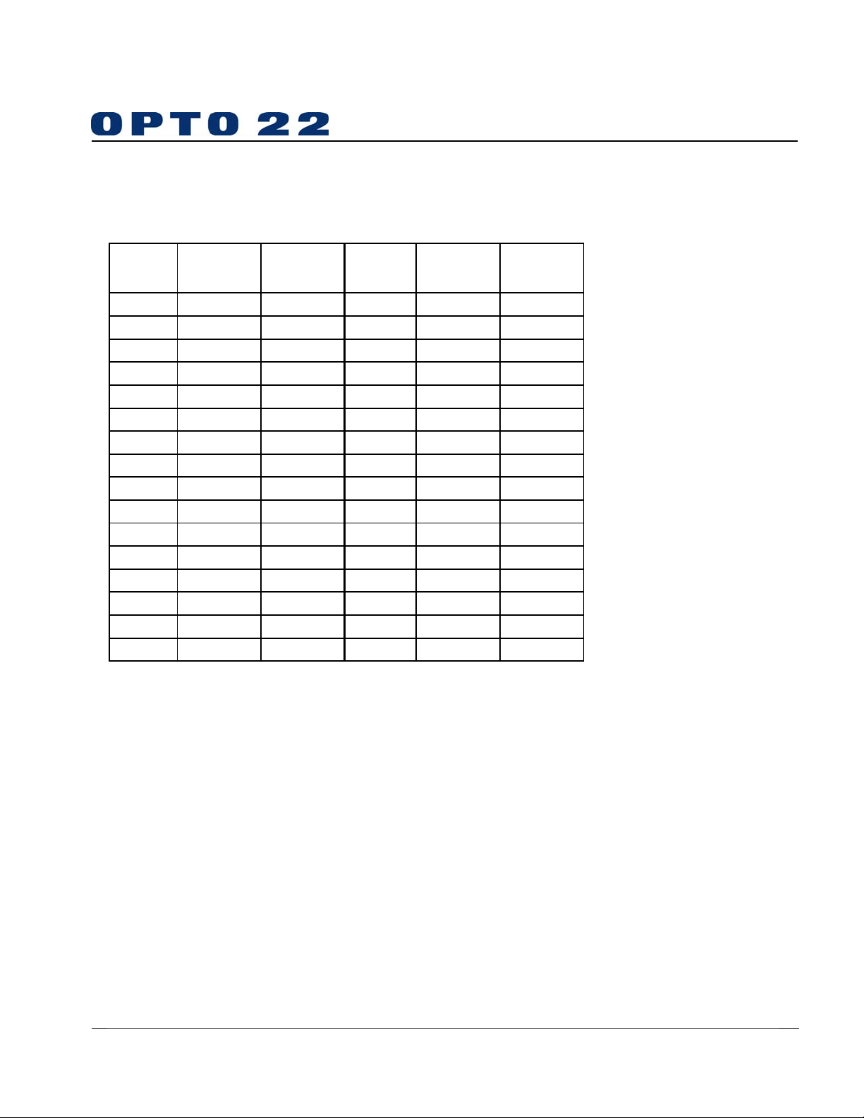
0 37 1 and 2 16 14 33 and 34
1 39 3 and 4 17 12 35 and 36
2 38 5 and 6 18 13 37 and 38
3 40 7 and 8 19 11 39 and 40
4 35 9 and 10 20 16 41 and 42
5 42 11 and 12 21 9 43 and 44
6 36 13 and 14 22 15 45 and 46
7 41 15 and 16 23 10 47 and 48
8 47 17 and 18 24 4 49 and 50
9 50 19 and 20 25 1 51 and 52
10 44 21 and 22 26 7 53 and 54
11 48 23 and 24 27 3 55 and 56
12 49 25 and 26 28 2 57 and 58
13 43 27 and 28 29 8 59 and 60
14 46 29 and 30 30 5 61 and 62
15 45 31 and 32 31 6 63 and 64
Control
(Header
Connector)
Field
(Terminal
Strip)
Module
Position
Control
(Header
Connector)
page 3/3
Field
(Terminal
Strip)
Notes:
1. Pins 17, 19, 21, 22, 23, 25, 26, 28, 30, 31, 32, and 34 on the
control connector are etch connected to the - terminal.
2. +VCC and the return are connected to terminals marked +
and -.
3. At each module position on the field terminal strip, the lower
number is always connected to pin 1 of the I/O module.
4. The +VCC connection requires +5 VDC.
© 1990–2001 Opto 22. All rights reserved. All trademarks, trade names, logos, and service marks referenced herein belong to their respective companies.
 Loading...