

Page 1

DATA SHEET
Form 2317-200617
PAGE 1
groov RIO
®
Features
Powered by either 10-32 VDC power supply or Power over
>>
Ethernet (PoE) (star topology only)
10 channels of multi-signal, multifunction inputs and outputs
>>
(GRV-R7-MM1001-10 model)
Analog I/O, temperature, discrete I/O, and mechanical relays
>
Two switched Gigabit Ethernet network interfaces for wired
>>
networks; supports star or daisy-chain topologies
Embedded web-based applications including groov
>
®
Manage,
Node-RED, and MQTT
USB port for adding devices like Wi-Fi adapter or USB memory
>
drive (user supplied)
Built-in security with encryption and authentication
>
DESCRIPTION
Opto 22’s groov RIO—remote Ethernet I/O for industrial internet of
things (IIoT) and automation applications—solves two main
problems with most remote I/O today:
First, specifying all the required components (rack, power supply,
bus coupler, module types, and more) is time-consuming,
difficult, and requires significant domain expertise.
Second, communicating data among field devices, control
systems, company software, and cloud services is complex and
costly, requiring PLCs, programming, and middleware.
groov RIO revolutionizes remote I/O by solving both problems.
One part number. A single part number includes built-in
multifunction, multi-signal I/O; an I/O processor; power over
Ethernet; and mounting without the need for a rack or chassis—
in a compact industrial package.
Built-in processing and communication. Web-based
configuration, flow logic software, efficient data communication
methods, and multiple operations technology (OT) and
information technology (IT) protocols simplify any IIoT or
automation application.
groov RIO is Edge I/O
GRV-R7-MM1001-10
With groov RIO, you can:
Place the unit almost anywhere for remote I/O and data
communications. groov RIO operates through a wide range of
operating temperatures (-20 to 70 °C), is UL/cUL listed, and
complies with the ATEX, Low Voltage, and EMC CE directives.
Supply power to groov RIO and field I/O through the ETH1
network interface, using Power over Ethernet (802.3af PoE Class 0)
connections. Or use the power supply terminals to connect to a
10-32 V DC power supply.
Connect the two switched Gigabit Ethernet network interfaces in
a daisy-chain configuration or in a standard star configuration.
Both interfaces use a single IP address.
Connect additional devices like a Wi-Fi adapter, a USB memory
stick (up to 32 GB), or a USB-to-serial adapter via the groov RIO’s
USB host port (additional devices are user supplied).
Simplify field connections using the 26-pin removable field I/O
termination connector with spring clamp wire retention.
Easily see the status of power, network, and I/O activity on the
unit’s LEDs.
Use embedded software to quickly set up data communications
between field devices and on-premises or cloud-based systems
and software.
These features make groov RIO a new kind of I/O product—edge I/O.
It does not require a PLC, PAC, or industrial PC, but is designed as an
intelligent, distributed I/O device to meet the needs of IIoT projects,
especially those that require data acquisition or communications.
© 2020 Opto 22. All rights reserved. Dimensions and specifications are subject to change. Brand or product names used herein are trademarks or registered trademarks of their respective companies or organizations.
Part Number
Part Description
GRV-R7-MM1001-10
groov RIO edge I/O; 8 multifunction channels, 2
form C
electromechanical
relay output channels
Page 2

DATA SHEET
Form 2317-200617
PAGE 2
Up and Running Faster
groov RIO’s single part number gives you everything you need for
edge I/O, plus options. With Power over Ethernet, you can avoid the
extra time and expense of routing power or adding a power supply
dedicated to groov RIO. Just run a Category 5e or 6 Ethernet cable
from a PoE-supplying network switch to ETH1—bringing power and
networking over a single cable. PoE can also power field I/O (for
details, see "Specifications" on page 8).
After you power up your groov RIO unit, open a web browser on a
computer or mobile device to connect to your RIO's IP address or
hostname. groov Manage—a web app that gives you command
center-like access to your groov RIO—opens so you can configure,
troubleshoot, and commission built-in I/O, networking, and security.
groov RIO as Edge I/O
Configure a Mix of Channels
The first product in the groov RIO family is the GRV-R7-MM1001-10, a
10-channel, multi-signal, multifunction edge I/O unit with over
61,260 unique field I/O combinations. (How is this possible? Take a
look at the wiring diagram on page 16 to see all the available
functions and input/output configurations. To understand how we
calculated these combinations, visit info.opto22.com/61260.)
Through groov Manage, you select a channel, configure its I/O signal,
select any function supported by the selected channel—such as
counting, latching, clamping, and more—and then save your
configuration. groov RIO begins converting signals into data that a
computer can understand as soon as field devices begin transmitting
signals.
groov RIO acts as edge I/O to
exchange data between OT field
devices (at bottom) and IT
computers and software (at top).
© 2020 Opto 22. All rights reserved. Dimensions and specifications are subject to change. Brand or product names used herein are trademarks or registered trademarks of their respective companies or organizations.
Page 3

DATA SHEET
Form 2317-200617
PAGE 3
Send Data Wherever You Like
Once the groov RIO unit is configured, continue to use groov Manage
to directly send data wherever you need it, without requiring a PLC or
middleware.
Configure and enable MQTT on RIO to securely send data—as
Sparkplug-B or string payloads—to MQTT brokers on premises or
in the cloud.
Create a data flow with the built-in Node-RED editor and runtime
to send data to cloud services, databases, other I/O channels, and
APIs through pre-built nodes.
Develop simple user interfaces (UIs) with Node-RED UI nodes and
serve them directly from RIO to any mobile or web-based device.
Security
groov RIO provides several features to help keep your data secure.
User account management—groov RIO has no default username or
password. You must set up a first Admin user account and remember
its username and password, as these user credentials are secure and
cannot be recovered. You can also create more users and set their
passwords and permissions.
VPN client—You can securely connect to groov RIO using a VPN.
Support is provided for OpenVPN servers.
Configurable firewall—Configure the device (or host) firewall in
groov RIO for greater security. You can control which ports, protocols,
and interfaces are open for incoming connections to the services
listening on each port number. For example, you should disable the
ports of unused protocols.
groov RIO in an Opto 22 Control Program
In addition to its use as autonomous edge I/O, groov RIO can also be
used to expand the scope of existing control programs or industrial
applications. You can add groov RIO units to monitor, control, and
collect data from field devices:
In a PAC Control™ strategy—With PAC Project™ Basic or
Professional Software Suite, add a groov RIO as an I/O unit,
configure your I/O points, then download your strategy to a:
– groov EPIC
– SNAP PAC controller or SoftPAC running PAC Controller
firmware 10.3 (also requires PAC Project 10.3).
In a CODESYS® application—Download and install the Opto 22
Library Package for CODESYS Development System, version
2.0.0.0. Update your application and you’ll be ready to add a
groov RIO and configure I/O points.
In a custom control program—You can access groov RIO I/O
programmatically through OptoMMP or REST APIs.
®
processor running firmware version 2.0.0
Leverage Existing groov and SNAP PAC
Knowledge
If you already have groov EPIC, a groov Box™, or SNAP PAC control
systems, you can expand your I/O footprint with the addition of
groov RIO units. groov RIO works as remote I/O with groov EPIC and
SNAP PACs, and it uses many of the same principles and technologies
found in your existing groov or SNAP PAC control system:
groov Manage for I/O configuration and other tools to help
manage your groov RIO
MQTT to transmit Sparkplug or string payloads
Node-RED for simple data flows
OpenVPN client to connect to an OpenVPN server running a
virtual private network
PAC Control for programming and I/O configuration
Distributed control—I/O features like counting, latching,
totalization, and minimum & maximum values continue to run
independently on the RIO unit, even if communication to the
controller is lost.
PID Loop Control
A groov RIO unit can independently solve PID loops when any analog
output is configured as the Control Output (CO) of the loop.
PAC Control is required to configure the PID loop function. Up to four
independent loops are supported, with configurable loop times.
More Ways To Exchange Data
groov RIO supports both OT and IT protocols and tools, making it
easier to safely move data among field devices and computer
networks. Choose the method that works best for you:
Modbus TCP/IP master—groov RIO is a Modbus TCP slave out of the
box. Use your favorite Modbus TCP master device or software to poll
RIO's I/O channels. A Modbus TCP calculator is built into RIO's
groov Manage application, helping you quickly find the Modbus Unit
ID and register for a memory map area.
C++ or .NET and free SDKs—With your favorite development tool
and our free SDKs, you can programmatically access I/O values on a
groov RIO by accessing the OptoMMP memory map locations of each
channel. An OptoMMP calculator is built into RIO's groov Manage,
making it simple to identify the MMP addresses of I/O channels and
their features.
HTTP/S, JSON, and REST APIs—The developer community has
embraced REST APIs as a method of accessing I/O with HTTP/S and
JSON. Opto 22 provides REST APIs for groov Manage, which you use to
access the I/O values on a RIO unit. A Swagger API document is built
into RIO to quickly access REST API calls and evaluate responses.
© 2020 Opto 22. All rights reserved. Dimensions and specifications are subject to change. Brand or product names used herein are trademarks or registered trademarks of their respective companies or organizations.
Page 4

DATA SHEET
Form 2317-200617
PAGE 4
MQTT broker/server—An efficient and robust publish/subscribe
protocol, MQTT is an ideal method of exchanging data for industrial
Ready to Run, or Need a Little Help? Try the
groov RIO Explorer
internet of things (IIoT) applications. groov RIO has support for MQTT
built in, requiring only a simple configuration to publish I/O data and
subscribe to commands as Sparkplug-B or string payloads.
We know the idea of contemplating over 61,260 unique field I/O
combinations is a bit much, so we created an online app to help you
select the right combination and correctly wire your field devices to
your groov RIO: The groov RIO Explorer.
With this web app, you can select which function you want on each
channel, and then the app displays the corresponding wiring
diagram. You can print out the wiring diagram or save it as an image
for reference.
groov RIO in an Opto 22 Control System, also Responding to a Modbus/TCP Master and Custom Program
In this diagram, groov RIO is an I/O unit
within a groov EPIC system. At the same
time, it can respond to a PC running a
custom control program and to a
Modbus/TCP master.
© 2020 Opto 22. All rights reserved. Dimensions and specifications are subject to change. Brand or product names used herein are trademarks or registered trademarks of their respective companies or organizations.
Page 5

DATA SHEET
Form 2317-200617
PAGE 5
LEDs, NETWORK INTERFACES, PORTS, AND CONNECTORS
The LEDs, network interfaces, USB port, and connectors (terminal and power supply) on the groov RIO offer features to help you review the status
and health of your groov RIO, as well as connect it to a power supply, a network, and field devices. For more information about these features and
how to utilize them, see groov RIO User’s Guide (form 2324).
LEDs
Reset Switch
LED Indicates
The status of power.
Power LED
Status LED
ETH0 LED
ETH1 LED
Discrete Channel
Indicators
POWER
STATUS
ETH0,
ETH1
Solid green—RIO is powered on.
Solid red—RIO is restarting.
Whether RIO is running or resetting.
Solid green—RIO is running normally.
Blinking green—RIO is starting (power on) or restarting (initiated by Reset Switch).
Blinking between green and red—RIO is resetting to factory
defaults.
Network connection speed and whether there is any transmission activity:
Solid green: 1 Gbps; transmission activity = No
Blinking green: 1 Gbps; transmission activity = Yes
Solid orange: 10 or 100 Mbps; transmission activity = No
Blinking orange:10 or 100 Mbps; transmission activity = Yes
Terminal Connector
Power Supply
Connectors
Reset Switch
This switch resets your groov RIO to factory defaults, erasing all the
changes you made to your RIO device and setting the firmware to the
version installed when it was shipped.
Discrete Channel Indicators
There are two columns of indicators on the face of RIO:
For discrete input channels, the column on the left indicates state.
For discrete output channels, the column on the right indicates
state.
When a channel is configured for discrete input or output, its
corresponding indicator lights up when the channel is on.
Terminal Connector
The terminal connector provides a spring-clamp wiring system to
securely connect the wires from your field devices to RIO. To learn
how to use a spring-clamp wiring system, see "Pinout and Wiring" on
page 15.
The terminal connector for GRV-R7-MM1001-10 is gray in color to
differentiate it from groov I/O module terminal connectors, which
have the same footprint as RIO. The difference in color helps you
remember that this terminal connector is designed for the
GRV-R7-MM1001-10 to accurately read thermocouple inputs.
Power Supply Connector
To supply power with an external power supply, Opto 22
recommends you follow these wiring guidelines:
© 2020 Opto 22. All rights reserved. Dimensions and specifications are subject to change. Brand or product names used herein are trademarks or registered trademarks of their respective companies or organizations.
Page 6

Use a 10 to 32 V DC power source or supply.
Use wire size 16 to 12 AWG. Keep the wires as short as possible.
Power Wiring Diagram
Before wiring the groov RIO to an external power supply, verify that
your wiring cables conform to the requirements described previously.
Network Ports
The Ethernet ports are switched, which means you can network them
in a daisy-chain configuration or in a standard star configuration using
either Ethernet port. Both ports use the same IP address.
DATA SHEET
Form 2317-200617
PAGE 6
USB port
Switched Ethernet
ports (2):
ETH0
ETH1
The network ports support speeds of up to 1 Gbps. Check the
category of your Ethernet cable to ensure you achieve the speeds you
expect from your network.
The ETH1 port, when connected to Power Sourcing Equipment
(PSE)—for example, a PoE switch—through a PoE-rated Ethernet
cable, can power RIO. This eliminates the need for a separate external
power supply. Opto 22 recommends you select a PSE that supports
IEEE 802.3af and has sufficient power available for all the powered
devices (PDs) connected to it.
USB Host Port
The USB host port can extend the capabilities of the groov RIO. You
can connect a:
WiFi adapter to add wireless connectivity.
USB-to-serial adapter to read and write data to serial devices.
USB memory stick to expand the storage space; for example, to
increase data logging capacity.
The wireless interface WLAN0 (which becomes available when you
plug in a WiFi adapter) does not provide access to other RIOs in a
daisy-chain configuration because this interface has a separate IP
address on a separate subnet.
Wireless Connectivity
The following WiFi USB adapters have been tested and proven to be
compatible with groov RIO:
Device Manufacturer Model
Linksys AE6000
TP-Link Archer T1U
Sabrent AC600
© 2020 Opto 22. All rights reserved. Dimensions and specifications are subject to change. Brand or product names used herein are trademarks or registered trademarks of their respective companies or organizations.
Page 7
DATA SHEET
Form 2317-200617
PAGE 7
FEATURES AND SPECIFICATIONS
Features
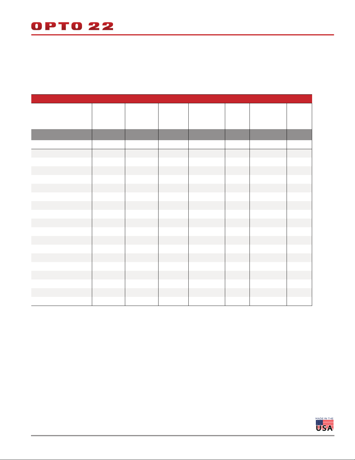
The following table lists the features available for each signal type. Note that some signal types are available only on specific channels, as listed in
the “Channels” row.
GRV-R7-MM1001-10 Signal Type
DI:
Discrete
Switch Input,
Powered
Channels 0-1 2-7 0-7 8-9 0-7 0-3 4-7
Features
On/off State x x x x
On/off Latching x
Counting x
On/off Totalization x
Frequency Measurement x
Period Measurement x
Pulse Measurement x
Scaling xxx
Offset and Gain x x
Minimum/Maximum Values x x
Average Filter Weight x x
Simple Moving Average
Analog Totalizing x x
Output Pulsing / TPO x
Ramping x
Clamping x
Watchdog Timeout Value x x x
Quality Indication xxx
DI:
Discrete
Switch Input,
Powered
DO:
DC Sinking
DO:
Form C
Mech. Relay
AI:
Voltage
ICTD
AI:
Current
Thermocouple
Millivolt
AO:
Voltage
Current
© 2020 Opto 22. All rights reserved. Dimensions and specifications are subject to change. Brand or product names used herein are trademarks or registered trademarks of their respective companies or organizations.
Page 8
DATA SHEET
Form 2317-200617
PAGE 8
Specifications
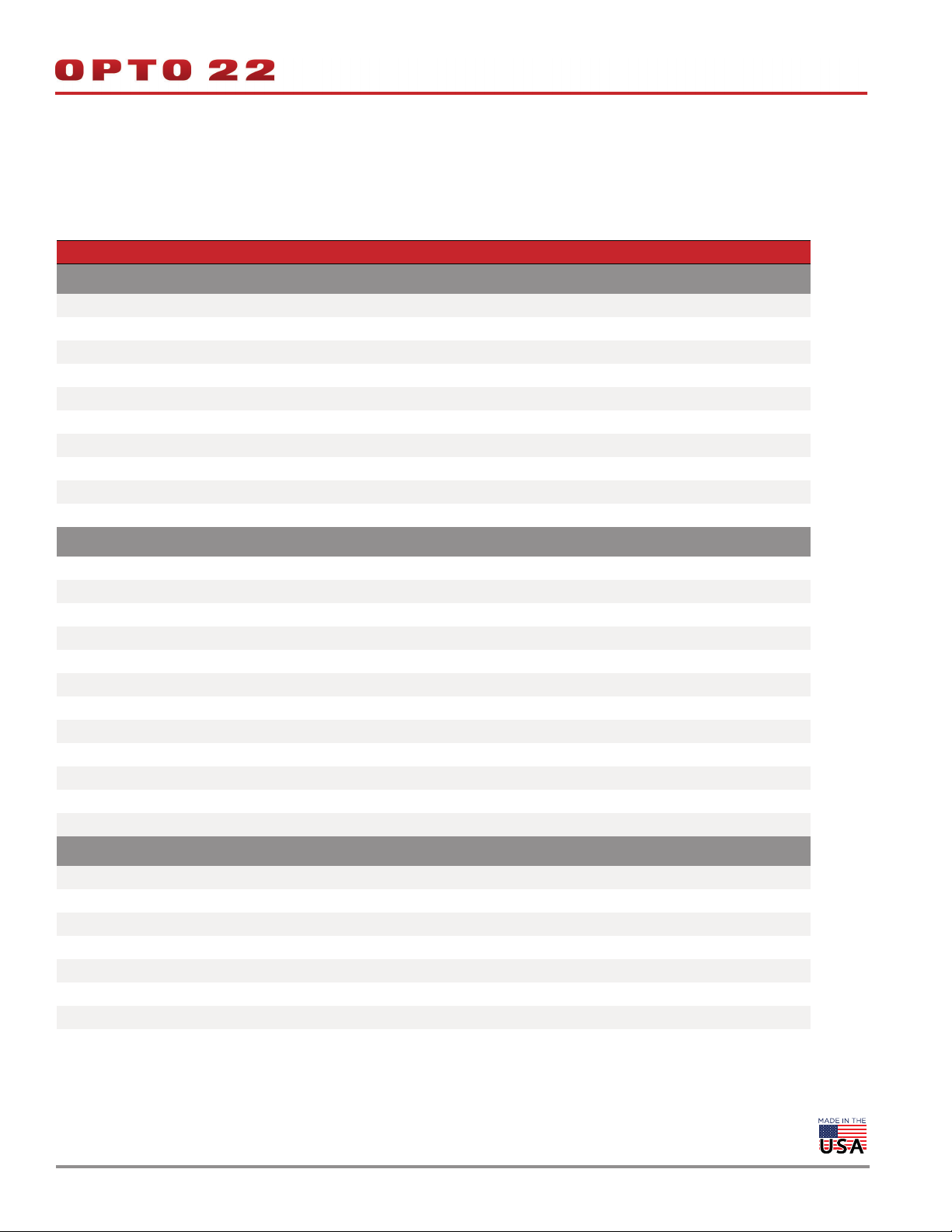
The specifications are divided into two categories: common and by-signal type. The common category (located at the bottom of the following
table) lists the specifications that apply to all channels, regardless of the signal type you select. The by-signal type category applies when the
channel is wired for that particular signal type.
Specification GRV-R7-MM1001-10
Voltage Input
Available Channels 0–7
Input Range 0–10 V DC
Over-range Limit 0–11 V DC
Resolution 0.5 mV
Accuracy ±0.05% of range (±5 mV)
Gain Temperature Coefficient 30 ppm/°C
Offset Temperature Coefficient 15 ppm/°C
Input Impedance > 425 kOhms
Data Refresh Time 450 ms
50 / 60 Hz rejection > 90 dB
Current Input
Available Channels 0–3
Input Range 0–20 mA
Over-range Limit 20.8 mA
Recommended Fuse 32–40 mA, Fast Acting (for example, Eaton S500-32-R)
Resolution 1.0 μA
Accuracy ±0.05% ( ±10 μA )
Gain Temperature Coefficient 30 ppm/°C
Offset Temperature Coefficient 15 ppm/°C
Input Voltage Drop (±10%) 0.9 V @ 4 mA, 2.0 V @ 20 mA, 25 °C
Equivalent Input Impedance (±10%) 225 Ohms @ 4 mA, 100 Ohms @ 20 mA, 25 °C
Data Refresh Time 450 ms
50 / 60 Hz rejection > 90 dB
ICTD Input
Available Channels 0–7
Input Range with ICTD Probe -40 to +100 °C
Resolution 0.04 °C
Accuracy with ICTD Probe ±1.0 °C (1.8 °F)
Gain Temperature Coefficient 30 ppm/°C
Offset Temperature Coefficient 60 ppm/°C
Data Refresh Time 450 ms
50 / 60 Hz rejection > 90 dB
© 2020 Opto 22. All rights reserved. Dimensions and specifications are subject to change. Brand or product names used herein are trademarks or registered trademarks of their respective companies or organizations.
Page 9
DATA SHEET
Form 2317-200617
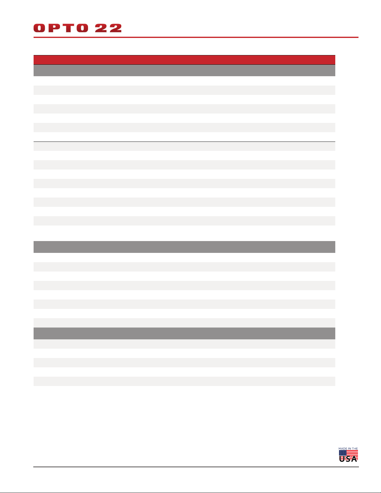
Specification GRV-R7-MM1001-10
Thermocouple Input
Available Channels 0–3 *
Nominal Input Range -75 to +75 mV
Full Scale Range -78 to +78 mV
Input Resolution 3 microvolts
Input Impedance > 1 megohm
Data Refresh Time 450 ms all channels
50 / 60 Hz rejection > 90 dB
Thermocouple ITS90 Types ± Accuracy / Resolution
B: 90 °C to 1,820 °C 7 °C / 0.4 °C
E: -80 °C to 1,000 °C 2 °C / 0.1 °C
J: -100 °C to 1,200 °C 2 °C / 0.1 °C
K: -80 °C to 1,372 °C 2 °C / 0.1 °C
N: -100 °C to 1,300 °C 3 °C / 0.1 °C
R: 100 °C to 1,768 °C 6 °C / 0.3 °C
S: 100 °C to 1,768 °C 6 °C / 0.3 °C
T: -60 °C to 400 °C 3 °C / 0.1 °C
* Note: To achieve the best thermocouple accuracy when also using current outputs or discrete outputs, always configure thermocouples
on the lowest channel numbers and outputs on the highest channel numbers.
Millivolt Input
Available Channels 0–3
Input Range -150 to +150 mV
Over-range Limits ±165.0 mV
Resolution 10 μV
Accuracy ±0.1% of Range (±150 μV)
Input Impedance > 1 MOhms
Data Refresh Time 450 ms
50 / 60 Hz rejection > 90 dB
Discrete DC Input
Available Channels 0–7
Input Voltage Range 5–30 V DC
Minimum ON Voltage 5.0 V
Maximum OFF Voltage 1.5 V
Input Impedance > 425 KOhms
Max. Input Frequency (50% square wave) 10000 Hz
PAGE 9
© 2020 Opto 22. All rights reserved. Dimensions and specifications are subject to change. Brand or product names used herein are trademarks or registered trademarks of their respective companies or organizations.
Page 10
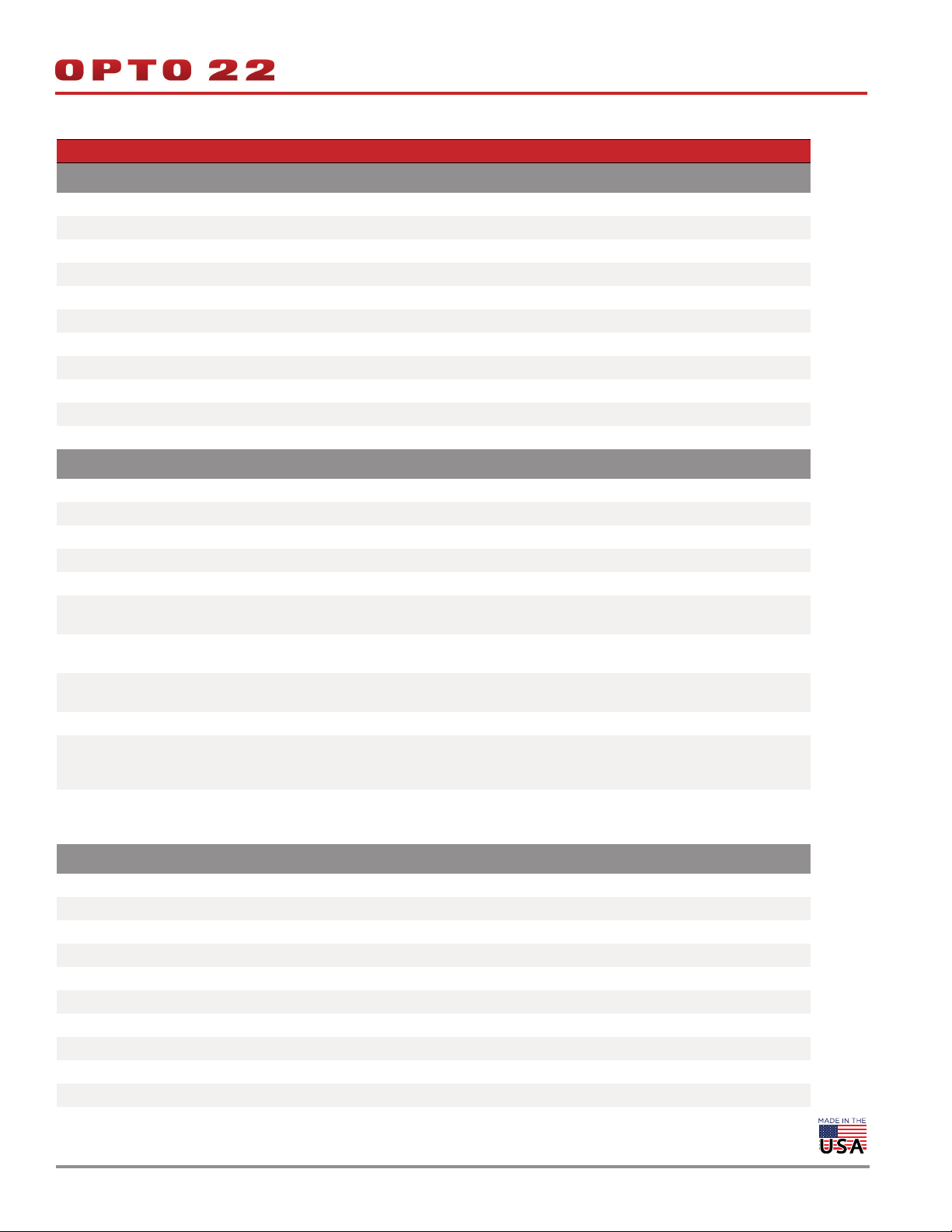
Specification GRV-R7-MM1001-10
Switch Input, Powered
Available Channels 0–7
Open Circuit Voltage (Switch Open) 10.5 V (minimum)
Channel Current Limit 1.1 mA max.
Channel Operating Current 0.63 mA typical
Minimum Off Resistance 3300 Ohms
Maximum On Resistance 1200 Ohms
Minimum ON Voltage 5 V
Maximum OFF Voltage 1.5 V
Maximum Continuous Survivable Input Voltage 32 V
Input Impedance > 425 KOhms
Max. Freq. (50% square wave) 10000 Hz
Discrete Counter Input
Available Channels 0–1
Input Voltage Range 5–30 V DC
'ON' Threshold 5 V
'OFF' Threshold 1.5 V
Input Impedance > 425 KOhms
Max. Frequency (50% square wave):
State, Latches, Counter
Max. Frequency (50% square wave):
On/Off pulse width, Period, Frequency
Max. Frequency (50% square wave):
On/Off totalization
Pulse Width Measurement Resolution 100 microseconds
Pulse Width Measurement Error
(50% square wave)
Period/Frequency Error
(50% square wave)
Discrete DC Sinking Output
Available Channels 0–7 (4-7 if using any thermocouple inputs)
Line Voltage Range 5–30 V DC
Maximum Continuous Current 1.0 A
Peak Current (< 10 ms) 4.0 A
Recommended Fuse / Circuit Breaker 1 A at 30 V DC
Output Voltage Drop 175 mV at 1 A
Off-State Leakage (per channel) < 80 μA at 24 V, -20 to +70 °C
Peak Blocking Voltage 32 V
TPO Period (min, max, resolution) 0.004, 4294967, 0.001
Turn On / Off Time 20 ms nominal.
10000 Hz
2000 Hz
750 Hz
0.1% 0 to 20 Hz.
1% 21 to 200 Hz.
5% 201 to 2000 Hz.
0.05% 0 to 20 Hz.
0.1% 21 to 200 Hz.
1% 201 to 2000 Hz.
DATA SHEET
Form 2317-200617
PAGE 10
© 2020 Opto 22. All rights reserved. Dimensions and specifications are subject to change. Brand or product names used herein are trademarks or registered trademarks of their respective companies or organizations.
Page 11
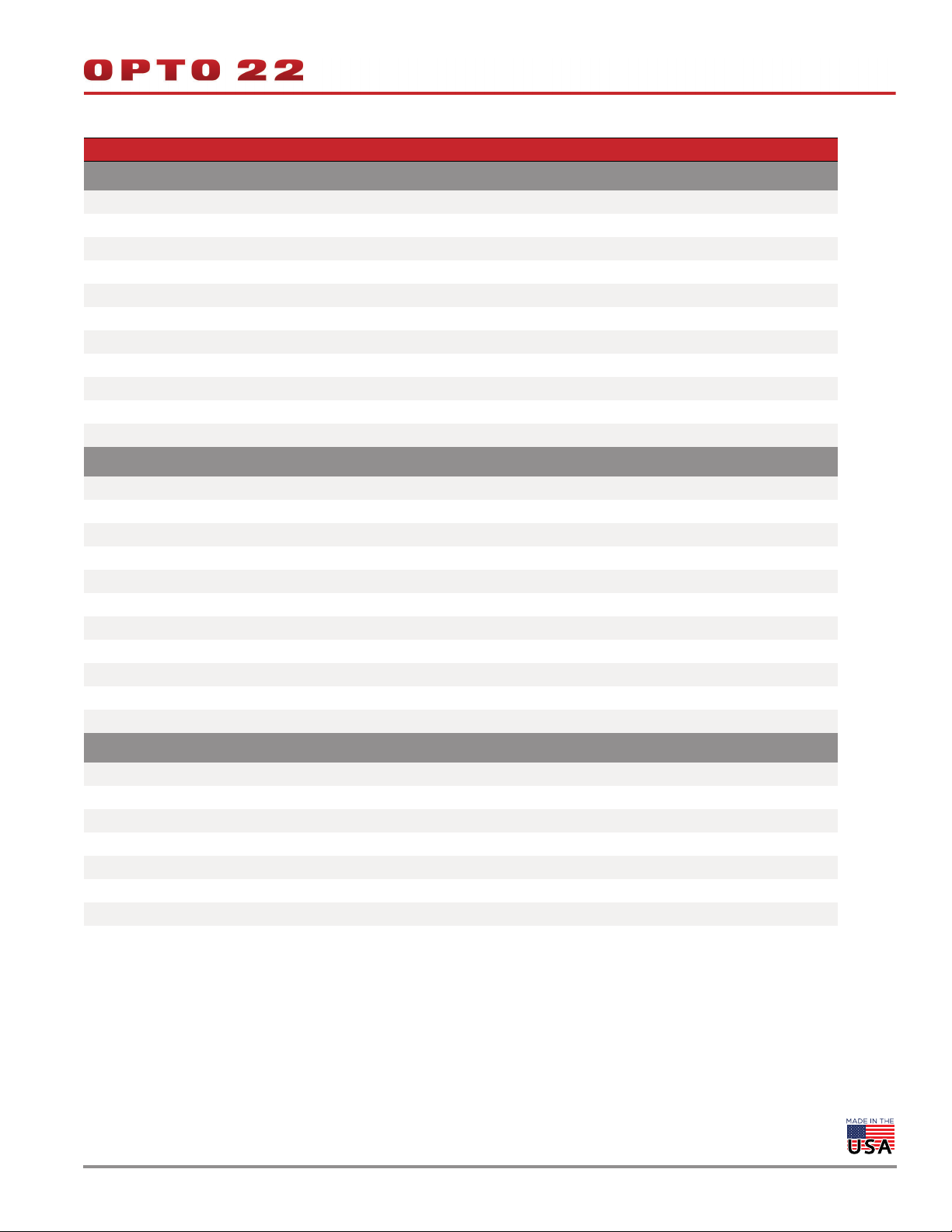
Specification GRV-R7-MM1001-10
Form C Relay Output
Available Channels 8, 9
Line Voltage Range 0–250 V AC or 5–30 V DC
Clamp Voltage 440 V nominal
Current Rating 5 A per channel
Surge Current 6 A peak for 1 second
Recommended Fuse / Circuit Breaker 5 A at 250 V AC / > 30 V DC per channel
Initial Contact Resistance < 100 milliohms
Turn On Time 8 ms
Turn Off Time 4 ms
Operating Life (to specification) Min. 30,000 cycles at max. ratings
Mechanical Life Min. 10,000,000 cycles
Voltage Output
Available Channels 4–7
Range 0–10 V
Resolution 2.5 mV
Accuracy ±0.2% of range (±20 mV)
Gain Temperature Coefficient 50 ppm/°C
Offset Temperature Coefficient 20 ppm/°C
Output Slew Rate > 15 V/ms
Minimum Load Resistance 7.5 kOhms
Output Impedance < 10 Ohms
Short-circuit Current 20 mA
Data Refresh Time Nominal 20 ms. Proportional to I/O scan time.
Current Output
Available Channels 4–7
Output Range 0–20 mA
Resolution 5 μA
Accuracy ±0.25% of range (±50 μA)
Gain Temperature Coefficient 60 ppm/°C
Output Slew Rate > 10 mA/ms
Maximum Loop Resistance 700 Ohms
Data Refresh Time Nominal 20 ms. Proportional to I/O scan time.
DATA SHEET
Form 2317-200617
PAGE 11
© 2020 Opto 22. All rights reserved. Dimensions and specifications are subject to change. Brand or product names used herein are trademarks or registered trademarks of their respective companies or organizations.
Page 12
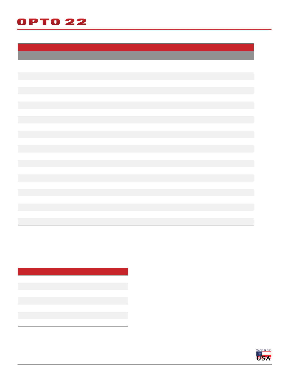
Specification GRV-R7-MM1001-10
Common Specifications
Ethernet
USB One Port, USB 2.0 HS
Memory 1 GB RAM, 2.5 GB user space
Power Supply 802.3af PoE Class 0 or 10–32 V DC
Power Consumption 10 W
Max. Survivable Input (channels 0 - 7) 32 V DC
Isolation (between channels 0 - 7) None
Isolation (between channel 8 or 9 and all others) 3000 V AC
Isolation (field to Ethernet / power input) 1500 V AC
Minimum GRV-EPIC-PR1 Firmware Version 2.0.0
Minimum PAC Project Version 10.3000
Minimum Library Package for CODESYS Version 2.0.0.0
Field Connector Wire Size 28–14 AWG
Torque, field connector screw 2.5 in-lb (0.28 N-m)
Power Connector Wire Size 22–14 AWG
Torque, DC power connector screws 7.0 in-lb (0.79 N-m)
Torque, panel mount tab screw 2.0 in-lb (0.23 N-m)
Temperature (operating) -20 °C to +70 °C
Temperature (storage) -40 °C to +85 °C
Relative Humidity (non-condensing) 5–95%
Agency Approvals
Warranty 30 months
Two switched Gigabit ports; daisy-chainable; ETH1 with 802.3af PoE powered
device (PD)
1 min.
rms
1 min.
rms
UL/cUL(Class 1 Div. 2); CE, ATEX(Category 3, Zone 2), RoHS; DFARS; CB Scheme
DATA SHEET
Form 2317-200617
PAGE 12
Wire Assignments
The following wire assignments apply to the thermocouple signal
type:
Type - + Range
B Red Gray +90 °C to +1,820 °C
E Red Purple -80 °C to +1,000 °C
J Red White -100 °C to +1,200 °C
K Red Yellow -80 °C to +1,372 °C
N Red Orange -100 °C to +1,300 °C
R,S Red Black 100 °C to +1,768 °C
T Red Blue -60 °C to +400 °C
© 2020 Opto 22. All rights reserved. Dimensions and specifications are subject to change. Brand or product names used herein are trademarks or registered trademarks of their respective companies or organizations.
Page 13
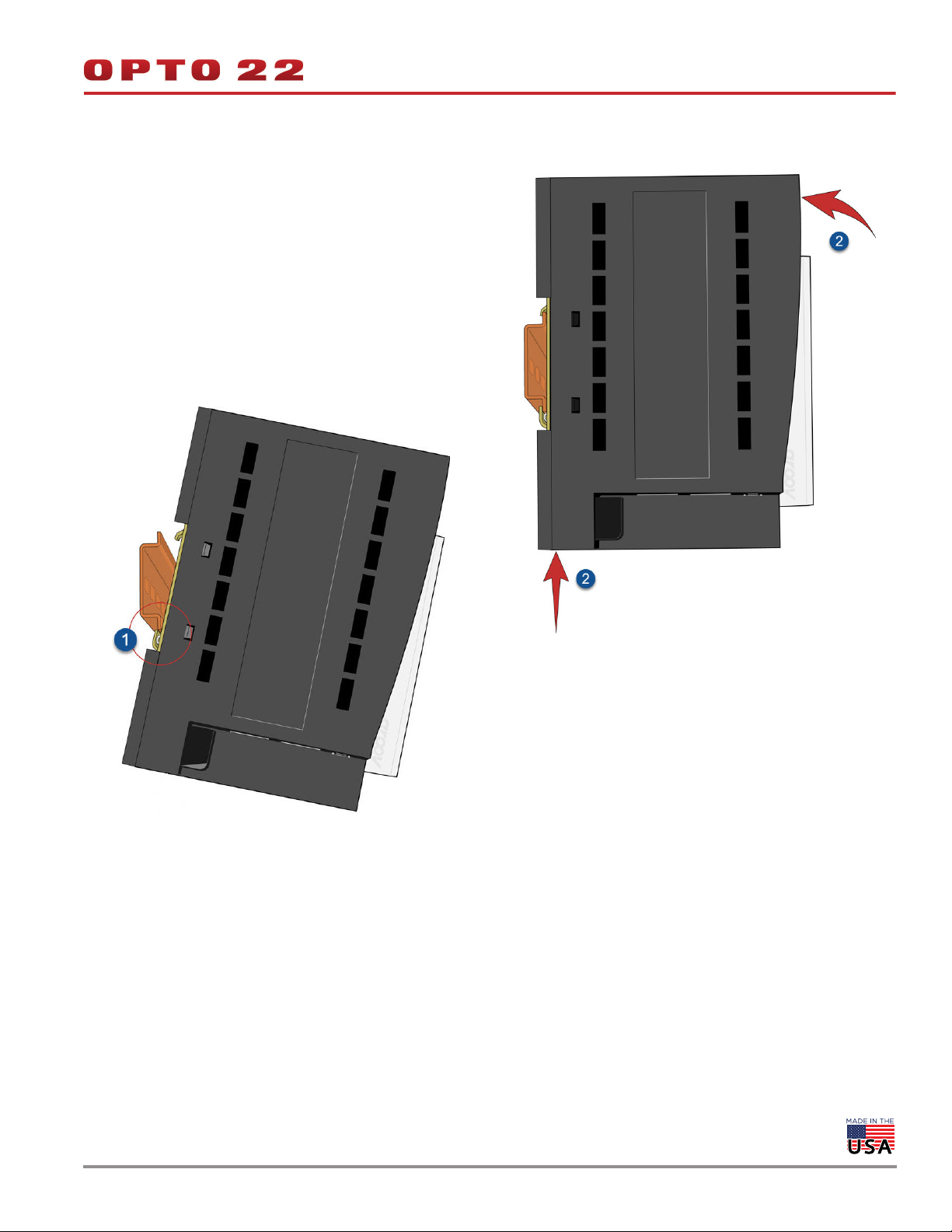
MOUNTING ON DIN RAIL
Before mounting your RIO:
Ensure that the vents around RIO are not obstructed.
Review "Orientation and Clearances" on page 14 to ensure good
ventilation and optimal performance.
The groov RIO is built with DIN rail adapters for use on 35 mm DIN rail.
No additional assembly is required.
To mount RIO to a DIN rail, follow these steps:
1. Hold RIO so that the Opto 22 logo is at the top and at an angle
such that the top of the DIN rail adapter is away from the DIN rail
and the bottom of the DIN rail adapter can slide behind the
bottom lip of the DIN rail.
DATA SHEET
Form 2317-200617
PAGE 13
2. Push the bottom part of RIO upward, making sure that you feel
the clip catch on to the rail, and simultaneously push the top half
of RIO toward the DIN rail until the top of the DIN rail adapter
engages the top lip of the DIN rail.
Before you release RIO, verify that the top and bottom of the DIN rail
adapters have engaged the DIN rail.
© 2020 Opto 22. All rights reserved. Dimensions and specifications are subject to change. Brand or product names used herein are trademarks or registered trademarks of their respective companies or organizations.
Page 14
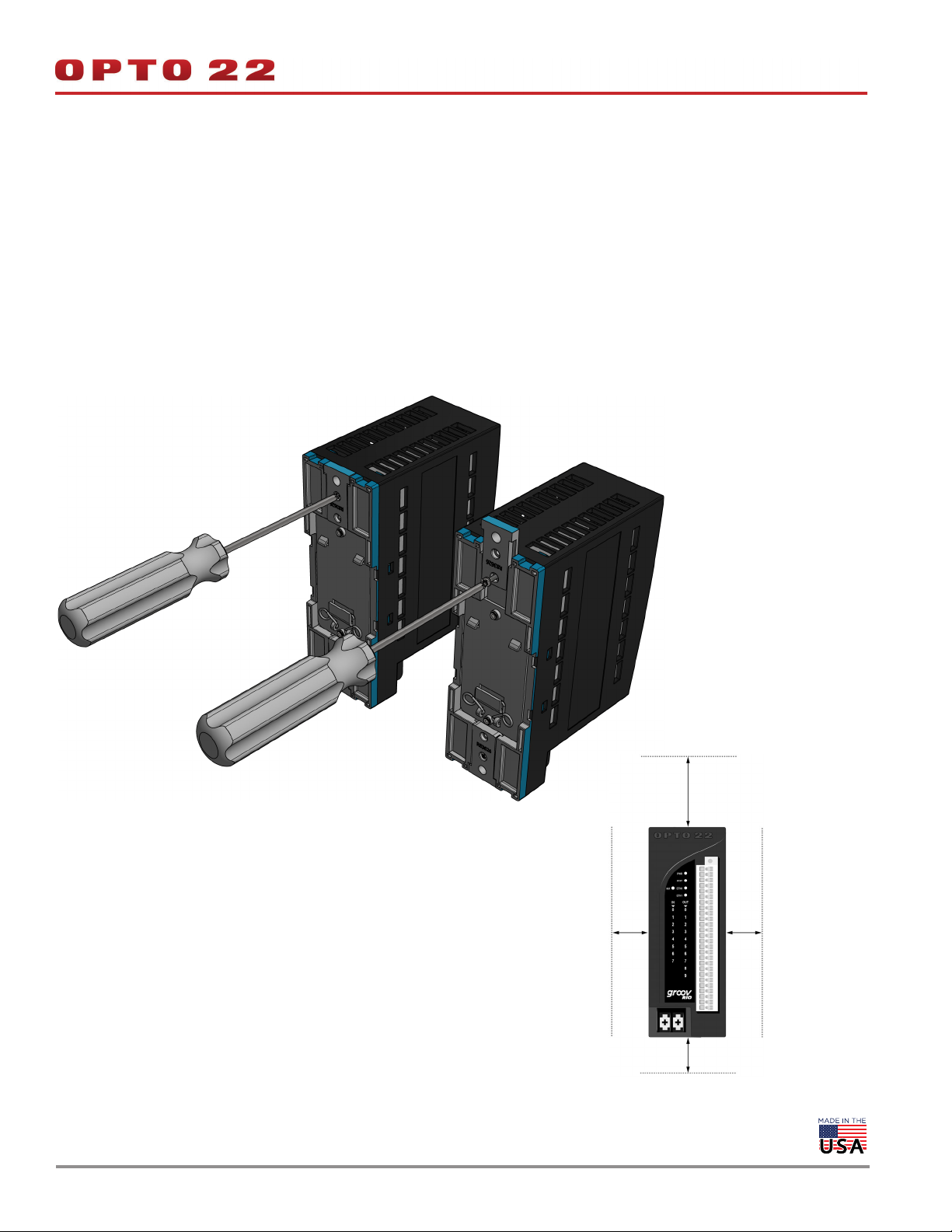
MOUNTING ON A PANEL
DATA SHEET
Form 2317-200617
PAGE 14
Before mounting your RIO:
Ensure that the vents around RIO are not obstructed.
Review “Orientation and Clearances” to ensure good ventilation
and optimal performance.
1. Flip the RIO so you can see the backside.
2. With a small Phillips screw driver, remove the screw on the tabs.
3. Slide tabs out so the middle hole on the tab aligns with the screw
hole on the RIO.
4. Reinsert the screw.
Now, you can use the RIO as a template to mark holes on the panel
and verify placement before attaching the RIO.
Attach the RIO with screws (not provided):
1. Drill the first screw into the tab up to the torque indicated in the
“Common Characteristics” section of the specifications (see
"Specifications" on page 8).
2. Drill the second screw into the second tab up to the torque
indicated.
3. Return to the first screw and re-tighten the screw up to the
torque indicated.
2 in.
ORIENTATION AND CLEARANCES
Make sure that there is a minimum of 2 inches clearance on the top,
and 1 inch clearance on the bottom, each side, and in front of RIO,
after it is mounted. Mount RIO as shown in the diagram: with the
Opto 22 logo at the top. Compliance with these guidelines will help
1 in.
ensure that the groov RIO performs as described in the specifications.
© 2020 Opto 22. All rights reserved. Dimensions and specifications are subject to change. Brand or product names used herein are trademarks or registered trademarks of their respective companies or organizations.
1 in.
1 in.
Page 15
PINOUT AND WIRING
DATA SHEET
Form 2317-200617
PAGE 15
Before you begin wiring, do the following tasks:
Select the appropriate wire. The terminal connectors are rated for
28–14 AWG wire. If you’re using stranded wire, you can make an
easier and better connection by tinning the strands or adding
ferrules.
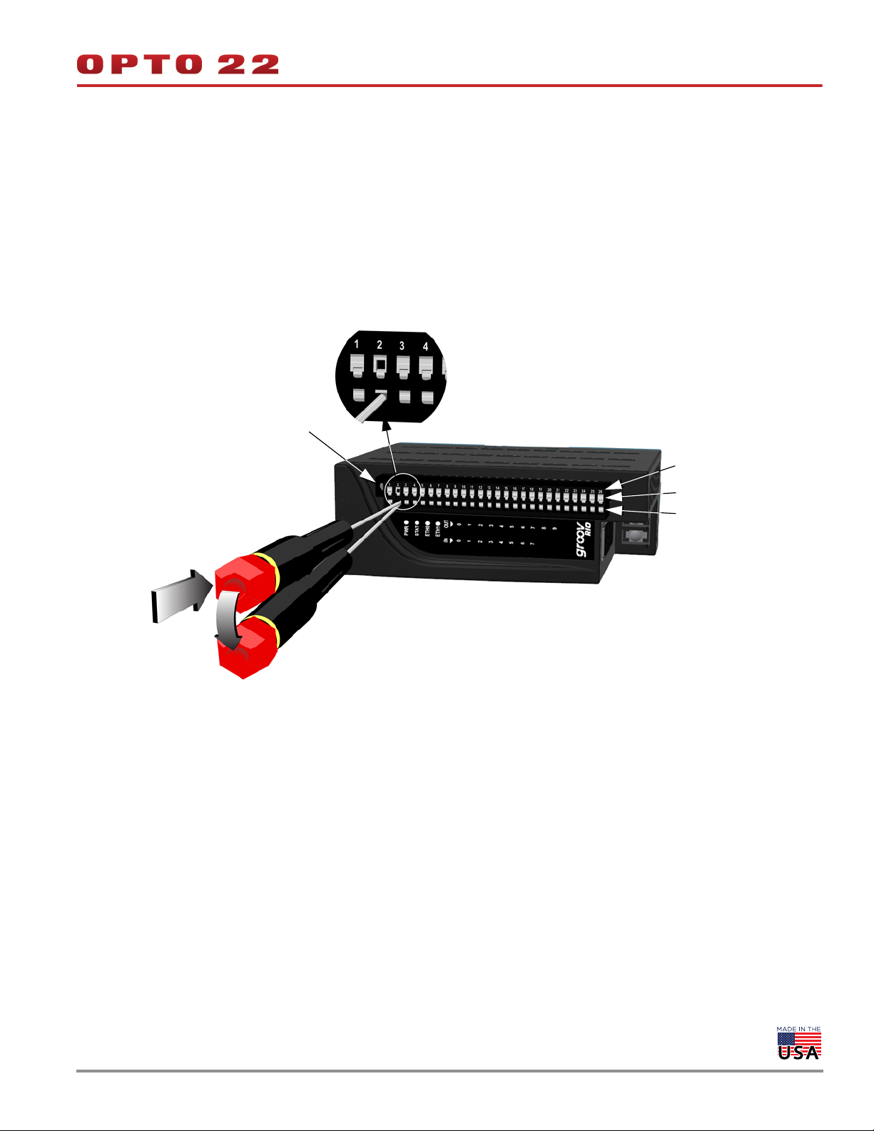
Ensure that you have the spring clamp tool supplied with your
groov RIO.
It may be easier to insert wires if you remove the terminal
connector from RIO. To remove the terminal connector, loosen the
Terminal connector screw
terminal connector screw at one end of the connector, then pull
the connector straight out.
If you have never used a spring-clamp wiring system, take a
moment to familiarize yourself with the diagram below. The
clamp release hole is where you will insert the spring clamp tool.
The field wiring hole is where you will insert your field wires.
If you look into the field wiring hole, you will see a highly reflective
surface. If you can see that surface, that means that the clamp is
closed.
In this example, pin 2’s clamp release hole and corresponding
field wiring hole are open.
Pin numbers
Field wiring holes
Clamp release holes
Follow these instructions to connect your field wires to RIO:
CAUTION: For electrical safety, turn off power to RIO and de-energize
field devices wired to the terminal connector before starting.
– Look into the field wiring hole. If it is dark, the clamp is open.
You can go to the next step.
– If you can still see the highly reflective surface, gently pull the
tool’s handle to the left until you feel it stop. Hold the tool in
1. Orient RIO or the terminal connector to match the wiring diagram
on the following page. To make it easier to handle the spring
clamp tool and the field wires, secure RIO by doing one of the
following:
– If you are working with the terminal connector while it is
attached to RIO, make sure RIO is attached securely to the
panel or DIN rail.
– If you are working only with the terminal connector, secure
that position. Look into the field wiring hole. If it is dark, the
clamp is open. You can go to the next step.
3. Insert the wire into the field wiring hole until it meets complete
resistance. Then pull out the spring clamp tool.
4. Test that the wire is secure by gently pulling on it. If the wire pulls
out, repeat steps 2 through 4.
To remove a wire, push the spring clamp tool into the clamp release
hole as described in step 2 above, and then pull the wire out.
the terminal connector with a clamp.
2. Slide the spring clamp tool into the clamp release hole, along the
left side, until you feel the end begin to meet some resistance.
Gently push the tool in a little more, until you feel it stop.
© 2020 Opto 22. All rights reserved. Dimensions and specifications are subject to change. Brand or product names used herein are trademarks or registered trademarks of their respective companies or organizations.
Page 16
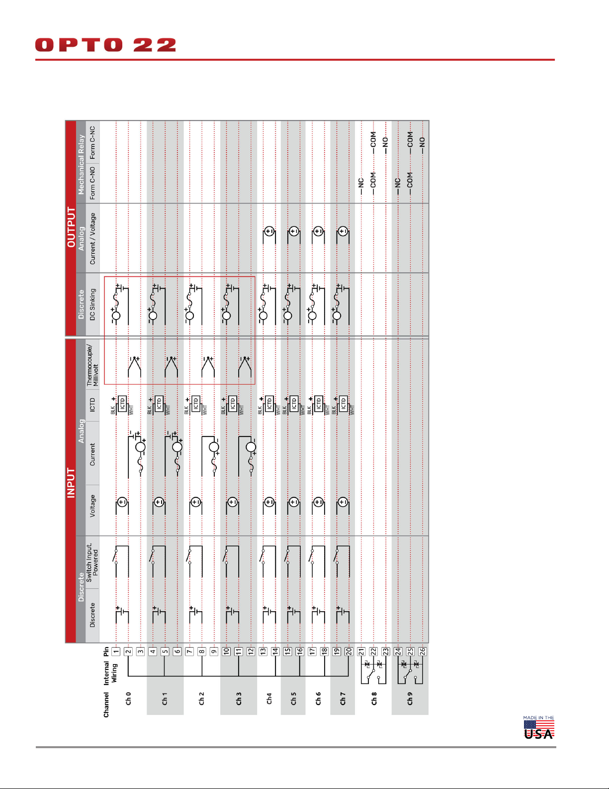
WIRING DIAGRAM
1112
DATA SHEET
Form 2317-200617
PAGE 16
3
powered transmitter. Wiring for externally powered transmitter is shown on channels 0 and 1. Wiring for a self powered transmitter is shown on
channels 2 and 3.
Notes:
1. You must supply external fusing.
2. Opto 22 recommends adding external fusing. Review the specification table for specific ratings. Compatible with an externally powered or self
© 2020 Opto 22. All rights reserved. Dimensions and specifications are subject to change. Brand or product names used herein are trademarks or registered trademarks of their respective companies or organizations.
3. Thermocouple inputs and discrete sinking outputs cannot be mixed on channels 0-3.
Page 17
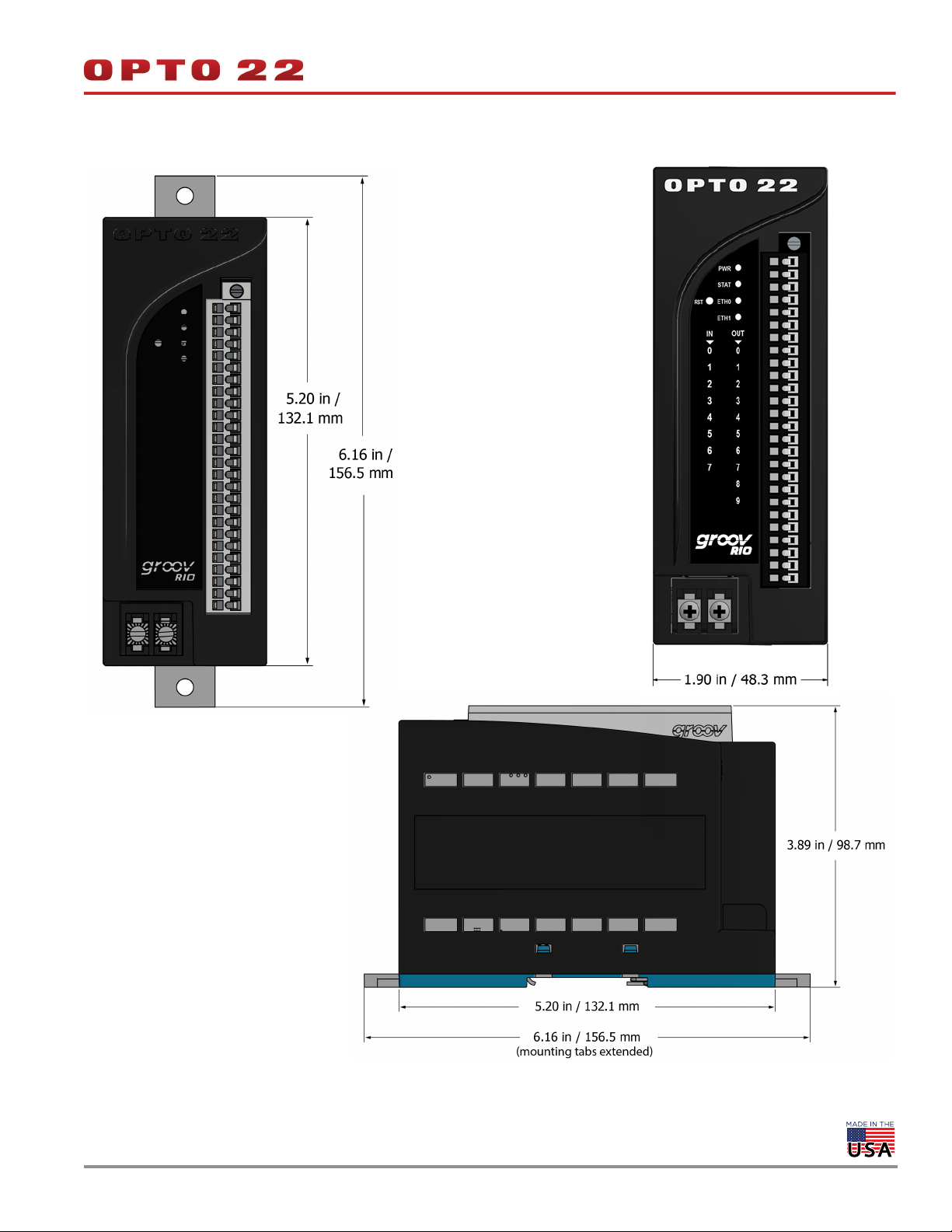
DIMENSIONS: groov RIO
DATA SHEET
Form 2317-200617
PAGE 17
Face Views
The image on the left shows the height (from
the top to the bottom) in two settings:
With the panel mounting tabs extended
(the larger dimension).
With the panel mounting tabs collapsed
(the smaller dimension).
The side view (below) also shows these
height dimensions.
The image on the right shows the width
(from one side to the other).
Side View
The image to the fight shows two
dimensions:
The depth, which measures from the face
to the back of the groov RIO.
The height, which measures from the top
to the bottom. The height varies,
depending on whether you have the
mounting tabs extended.
© 2020 Opto 22. All rights reserved. Dimensions and specifications are subject to change. Brand or product names used herein are trademarks or registered trademarks of their respective companies or organizations.
Page 18
More about Opto 22
PRODUCTS
Opto 22 develops and manufactures reliable, easy-to-use, open
standards-based hardware and software products. Industrial
automation, process control, building automation, industrial
refrigeration, remote monitoring, data acquisition, and industrial
internet of things (IIoT) applications worldwide all rely on Opto 22.
groov EPIC® System
Opto 22’s groov Edge Programmable
Industrial Controller (EPIC) system gives
you an industrially hardened system with
guaranteed-for-life I/O, a flexible Linux®based processor with gateway functions,
and software for your automation and IIoT
applications.
groov EPIC I/O
groov I/O connects locally to sensors and
equipment with up to 24 channels on each I/O module. Modules
have a spring-clamp terminal strip, integrated wireway, swing-away
cover, and LEDs indicating module health and discrete channel status.
groov I/O is hot swappable, UL Hazardous Locations approved, and
ATEX compliant.
groov EPIC Processor
The heart of the system is the groov EPIC processor. It handles a wide
range of digital, analog, and serial functions for data collection,
remote monitoring, process control, and discrete and hybrid
manufacturing.
In addition, the EPIC provides secure data communications among
physical assets, control systems, software applications, and online
services, both on premises and in the cloud.
Configuring and troubleshooting I/O and networking is easier with
the EPIC’s integrated high-resolution color touchscreen. Authorized
users can manage the system locally on the touchscreen or on a
monitor connected via the HDMI or USB ports.
groov RIO
groov RIO revolutionizes remote I/O by offering a single, compact,
PoE-powered industrial package with web-based configuration,
commissioning, and flow logic software built in, plus support for
multiple OT and IT protocols.
Standing alone, it meets the needs of small, variable I/O count
applications, especially those that require
data logging or data communications,
commonly found in IIoT applications.
groov RIO can also be used with a
Modbus/TCP master or as remote I/O for
a groov EPIC system.
Older products
From solid state relays (our first products)
to world-famous G4 and SNAP I/O, to
SNAP PAC controllers, older Opto 22
products are still supported and still
doing the job at thousands of installations worldwide. You can count
on us to give you the reliability and service you expect, now and in the
future.
QUALITY
Founded in 1974, Opto 22 has established a worldwide reputation for
high-quality products. All are made in the U.S.A. at our manufacturing
facility in Temecula, California.
Because we test each product twice before it leaves our factory rather
than testing a sample of each batch, we can afford to guarantee most
solid-state relays and optically isolated I/O modules for life.
groov EPIC Software
Software included in the groov EPIC processor:
PAC Control engine to run PAC Control and PAC Display
CODESYS Runtime engine to run IEC61131-3 compliant programs
built with CODESYS Development System
Optional access to the Linux operating system through a secure
shell (SSH) to download and run custom applications
groov View for building your own device-independent HMI,
viewable on the touchscreen, PCs, and mobile devices
Node-RED for creating simple logic flows from pre-built nodes
Ignition Edge® from Inductive Automation®, with OPC-UA drivers
to Allen-Bradley®, Siemens®, and other control systems, and MQTT
communications with Sparkplug for efficient IIoT data transfer
© 2001–2020 Opto 22. All rights reserved. Dimensions and specifications are subject to change. Brand or product names used herein are trademarks or registered trademarks of their respective companies or organizations.
Form 1335-200129
 Loading...