

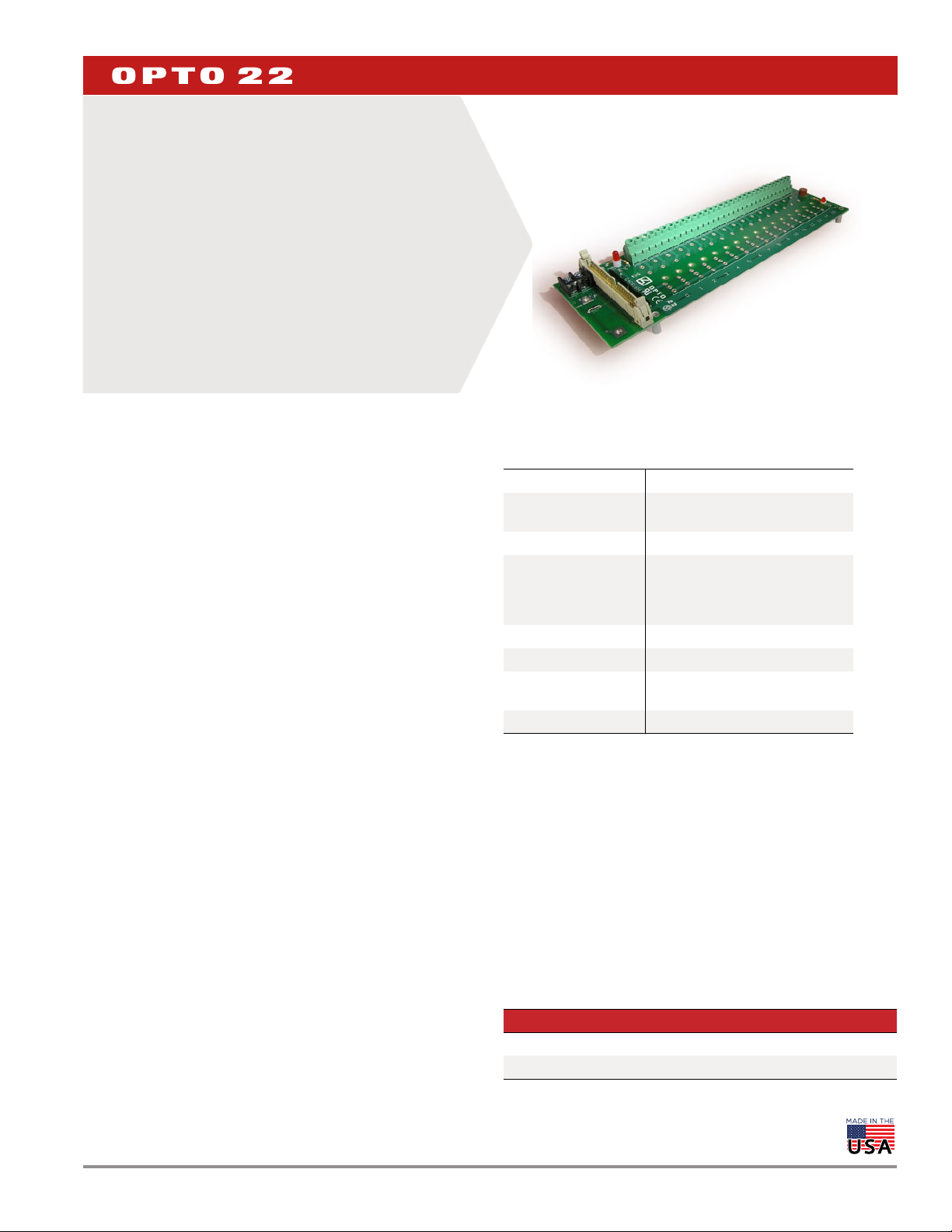
G4 DIGITAL O/I MOUNTING RACKS
(HEAD CONNECTOR)
Features
Available in 16- and 8-channel models
>
Require minimum panel space
>
Built-in fuse tester
>
Spare 1 A fuse on board; can accept 5A fuse
>
Power indicator LED
>
UL recognized; CSA certified; CE, RoHS, and DFARS approved
>
For field power, use a single 5, 15, or 24 VDC power supply
>
DESCRIPTION
The G4PB16H and G4PB8H Digital I/O Mounting Racks are designed
for use with G4 digital I/O modules. The G4PB8H accepts up to 8
digital I/O modules, and the G4PB16H accepts 16.
Both racks work with Opto 22’s PBSA, PBSB, and PBSC power supplies.
Logic supply is fused with a 1 A fuse, which, if desired, can be
swapped out for a 5 A fuse (sold separately).
Barrier strips with screw terminals provide the field and mounting
rack power connections. I/O modules are secured to the mounting
rack with a threaded captive hold-down screw. You can insert and
remove modules easily and quickly without disturbing field wiring.
For logic connections, the header connector accommodates the
following devices:
Standard 50-pin cable
Optomux® E1 brain board
Optomux B1 brain board
Pamux® B5 brain board
mistic™ B100 brain board
Digital I/O Carrier Board for Raspberry Pi® (part number
OPTO-P1-40P)
DATA SHEET
Form 0274-190417
G4PB16H
SPECIFICATIONS
Interface Connectors
Field Screw-type barrier strip
accommodates up to 10 AWG wire
Control 50-conductor header connector
Power Two-position screw terminal
(used with a 5.00 VDC +0.1
power source) or
Opto 22 PBSA/B/C Power Supply
Operating Temperature 0 to 70 °C
Relative Humidity 95% humidity, non-condensing
Agency Approvals
Warranty 30 months from date of manufacture
UL recognized; CSA approved;
compliant with CE, RoHS, DFARS
PAGE 1
Part Numbers
Part Description
G4PB16H G4 16-Channel Mounting Rack with Header Connector
G4PB8H G4 8-Channel Mounting Rack with Header Connector
© 2002–2019 Opto 22. All rights reserved. Dimensions and specifications are subject to change. Brand or product names used herein are trademarks or registered trademarks of their respective companies or organizations.
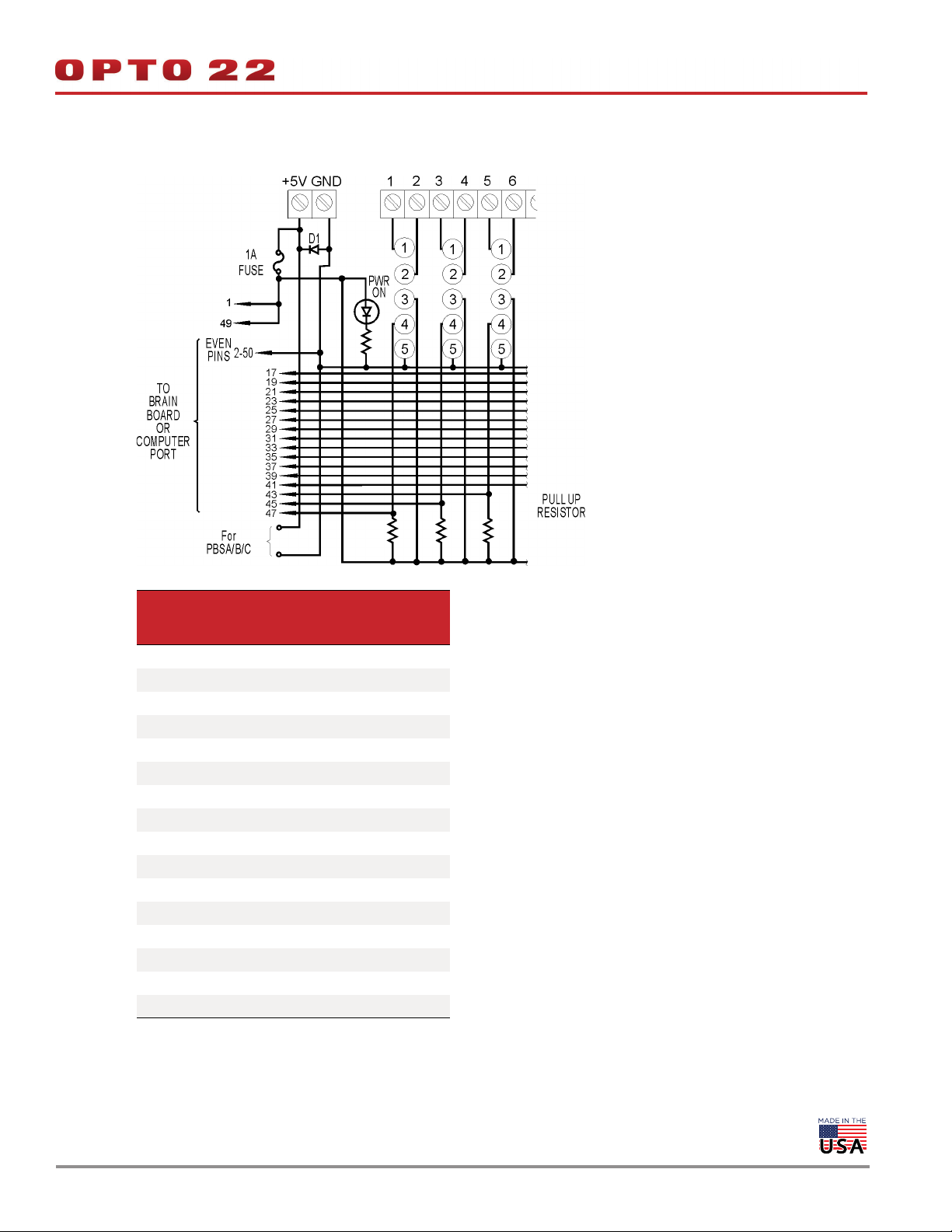
G4PB16H CONNECTIONS
DATA SHEET
Form 0274-190417
PAGE 2
Module
Position
0 47 1 and 2
1 45 3 and 4
2 43 5 and 6
3 41 7 and 8
4 39 9 and 10
5 37 11 and 12
6 35 13 and 14
7 33 15 and 16
8 31 17 and 18
9 29 19 and 20
10 27 21 and 22
11 25 23 and 24
12 23 25 and 26
13 21 27 and 28
14 19 29 and 30
15 17 31 and 32
Control
(Header
Connector)
(Terminal Strip)
Field
Notes:
1. Even pins on control connector are
connected by etch to common.
2. +VCC and return connected to terminals
marked +5V and GND.
3. At each module position on the field
terminal strip, the lower number is always
connected to pin 1 of the I/O module.
4. Use only 5 VDC logic modules when using
the mounting rack with a brain board.
© 2002–2019 Opto 22. All rights reserved. Dimensions and specifications are subject to change. Brand or product names used herein are trademarks or registered trademarks of their respective companies or organizations.
 Loading...