

Page 1

DS-C33 II Series
User’s Manual
www.opti-ups.com
Page 2

Contents
1. Preface ........................................................................................................................................................... 3
1-1 Introduction ......................................................................................................................................... 3
1-2 Safe Instructions and Warnings ........................................................................................................... 3
2. System Framework......................................................................................................................................... 4
2-1 Block Diagram ...................................................................................................................................... 4
2-2 System Major Module Function Introduction...................................................................................... 5
2-3 System Operation Modes ..................................................................................................................... 6
3. Touch Display Panel (HMI, Human Machine Interface) ................................................................................. 8
3-1 Introduction ......................................................................................................................................... 8
3-2 LCD Panel ............................................................................................................................................. 8
4. Fixation and Installation ............................................................................................................................... 13
4-1 Fixation ............................................................................................................................................... 13
4-2 Installation.......................................................................................................................................... 21
5. Operation Procedures .................................................................................................................................. 26
5-1 Power-on ............................................................................................................................................ 26
5-2 Power-off............................................................................................................................................ 28
5-3 Maintenance Bypass .......................................................................................................................... 28
5-4 Resumption from Maintenance Procedures ...................................................................................... 28
5-5 Emergency Power Off ........................................................................................................................ 28
5-6 Dry Contact Communication .............................................................................................................. 30
6. Maintenance and Storage ............................................................................................................................ 31
7. Troubleshooting ........................................................................................................................................... 31
8. Specifications ............................................................................................................................................... 32
9. Contact Information ..................................................................................................................................... 34
Page 3
1. Preface
1-1 Introduction
DS-C33 II series features an advanced DSP chip as a system core processor. Wide range capacity from 10KVA
to 200KVA meets a verity of load demands and extends the capacity up to 400KVA through paralleling. High
reliability and rapid transient response fit for critical equipments such as semiconductor, SMT and
communication facilities, etc.
HMI (Human machine interface) touch screen panel provides a user-friendly VIS (visual integrated system)
for real-time monitoring, easy maintenance. Fan operation depending on load condition achieves noise
reduction and energy consumption decrease. DS-C33 II is the best choice for dealing with critical power
needs.
1-2 Safe Instructions and Warnings
For safe operation, warning marks for DS-C33 series are:
DO NOT TOUCH DANGEROUS HIGH VOLTAGE
Dangerous high voltage mark pasted indicates high DC voltage. Do not touch the surface marked with it.
When batteries are being discharged (during blackouts), do not switch off (open circuit) the battery
magnetic switch to avoid danger.
Batteries are consumptive parts. Check if battery voltage, current and appearance are normal every 4
months to make sure the UPS operates normally and safely. If batteries are overheated or deformed,
replace them with new batteries to avoid fire danger because of lead acid liquid leakage.
Without using the UPS or AC mains supply for a long time, remove UPS’s battery fuses, switch off the
battery pack’s breakers or remove batteries in order not to damage batteries.
UPS is power system equipment and it requires grounding. The load of the UPS requires a separate
grounding.
PS: The contents of this manual are subject to change or modification without prior notice.
Page 4
2. System Framework
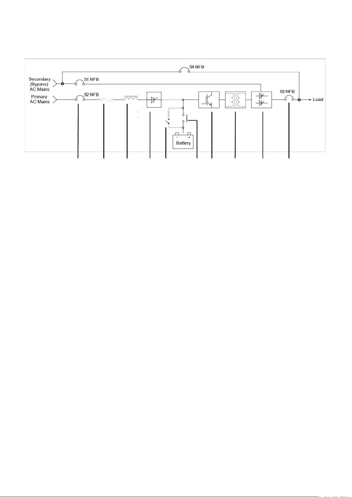
2-1 Block Diagram
(1) (8)
(2) (3) (4) (5) (6) (7) (9) (10) (11) (12)
Fig. 2-1
(1) Secondary (Bypass) AC Mains NFB (S1 NFB)
(2) Primary AC Mains NFB (S2 NFB)
(3) Input Fuse
(4) Three-phase AC Inductor
(5) Rectifier/ Charger
(6) Battery Auxiliary Relay
(7) Battery MS (Magnetic Switch)
(8) Manual Bypass Maintenance NFB (S4 NFB)
(9) Inverter Module
(10) Inverter Isolation Transformer
(11) STS (Static Transfer Switch)
(12) Output NFB (S3 NFB)
Page 5

2-2 System Major Module Function Introduction
2-2-1 Rectifier
(1) Utilization of SCRs inverts AC voltage to DC voltage.
(2) Combination of CPLD and DSP make the rectifier more stable and reliable.
(3) Over-voltage protection.
(4) DC voltage soft starter.
(5) Float charging and equalization charging modes support.
(6) Float charging time is adjustable and available on the display panel.
(7) Battery test can be done with continuous AC supply.
(8) Manual and automatic periodic battery tests are settable on the display panel.
(9) Charging current is settable on the display panel.
(10) 12-pulse rectifier is optional for reducing input THD.
2-2-2 Inverter
(1) IGBT as a power component is adopted.
(2) The inverter is equipped with an output isolation transformer.
(3) DSP digital control processing technology is applied to improve analogue components’ aging,
temperature drift and for the purpose of using fewer components.
(4) Integrated A/D signal processing, 12-bit resolution and fast transition are featured.
(5) Heat dissipation structure combined with temperature protection makes the inverter more reliable.
2-2-3 Static Transfer Switch
(1) Use of SCR for the static transfer function of the inverter and the bypass can work in a variety of
environments.
(2) High-frequency technology isolates the trigger circuit. The trigger circuit effectively triggers the STS
and results in switching without disconnection between inverter and bypass loops.
(3) STS has triggering conditions for disable, bypass and inverter loops and is fully controlled by DSP.
2-2-4 Emergency Power Off (EPO)
For emergency or force majeure in operation, EPO is used by pressing the button for shutting down the UPS
immediately. Press EPO button to completely stop the UPS and EPO light is turned on (Fig 2-2-4 Left). Press
EPO button and select the button of “Turn off inverter” on the display panel to restart the UPS and EPO
light is turned off (Fig 2-2-4 Right).
Fig. 2-2-4
Page 6
2-3 System Operation Modes
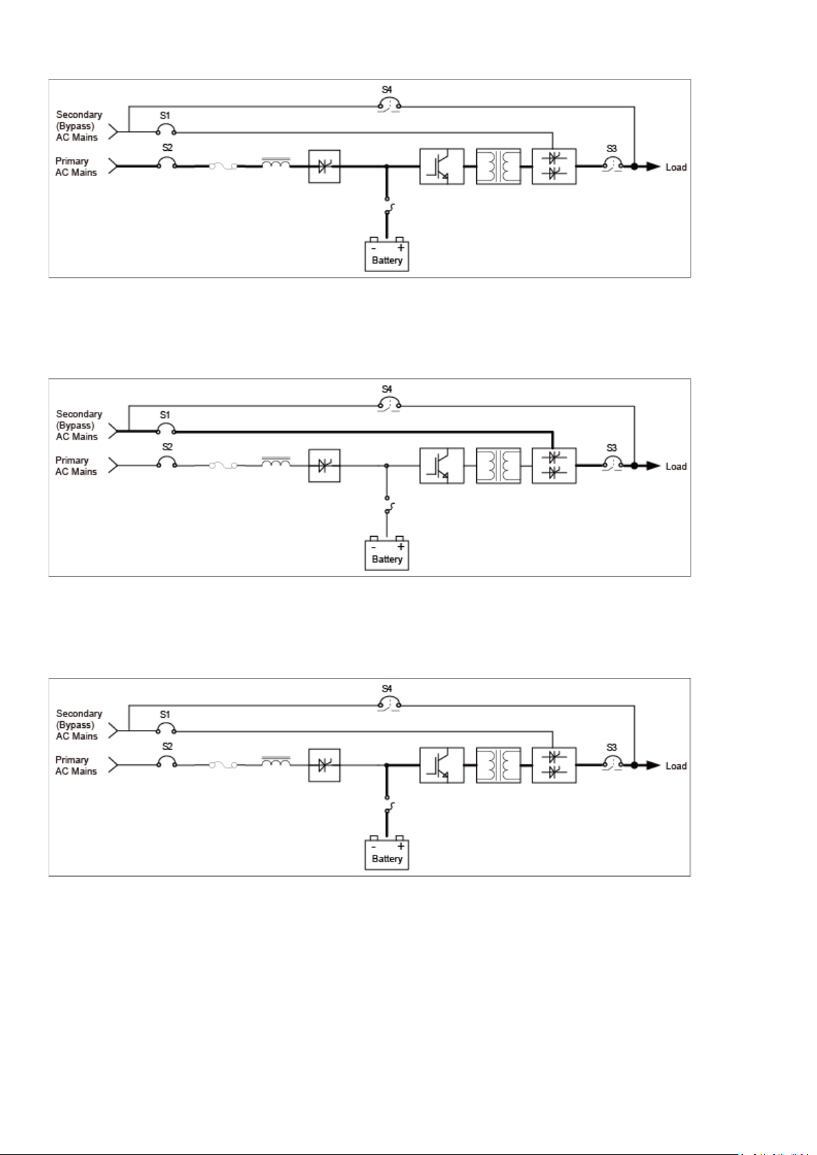
2-3-1 Normal Operation
Fig. 2-3-1 Normal Operation
AC mains power goes through the rectifier, the inverter, the STS to the load.
2-3-2 Bypass Operation
Fig. 2-3-2 Bypass Operation
AC mains power goes through the bypass path and the STS to the load.
2-3-3 Battery Supply Operation
Fig. 2-3-3 Battery Supply Operation
The power supplied from batteries goes through the inverter and the STS to the load. When the load
consumes power from the batteries, its backup time depends on the battery capacity and the load power
consumption. Therefore, save your data and turn off the personal computers as soon as possible when a
blackout occurs.
Page 7

2-3-4 Maintenance Bypass Operation
Fig. 2-3-4 Maintenance Bypass Operation
AC mains power goes through the maintenance bypass switch to the load. This mode is only for trained
professionals to do regular system and cleaning maintenance.
2-3-5 EPO Switch
Fig. 2-3-5 EPO Switch
UPS is going to be turned off and outputs no power in this mode for emergency.
Page 8
3. Touch Display Panel (HMI, Human Machine Interface)
3-1 Introduction
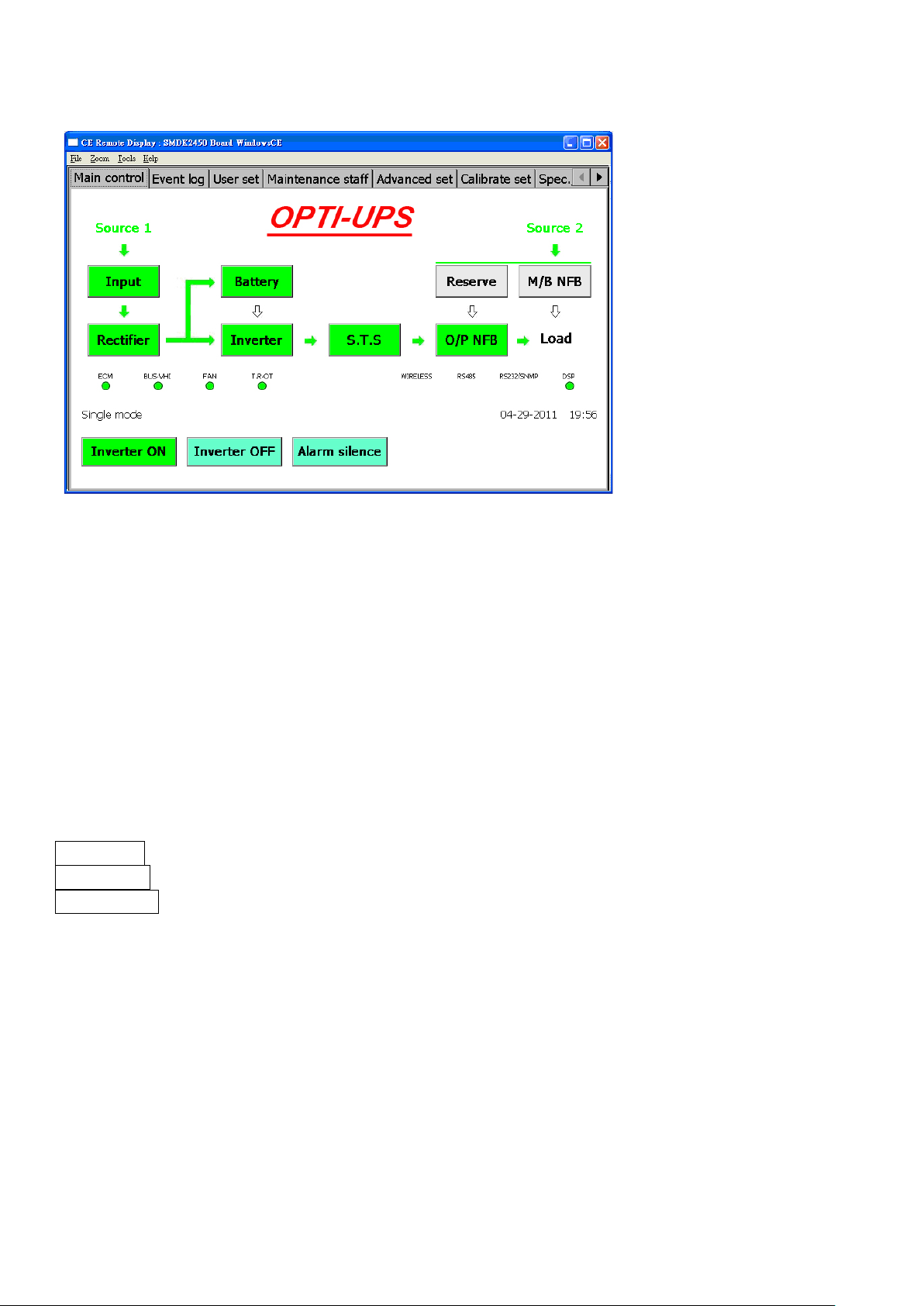
Fig. 3-1
DS-C33 II has an 800x480px TFT touch screen display panel. It can be set and controlled, and its status and
information are displayed on the display panel shown as Fig.3-1.
3-2 LCD Panel
The display consists of main control, event log, user set, maintenance staff, advanced set, calibrate set and
spec./service categories (tabs) and their corresponding pages.
3-2-1 Main control
Main control displays system operation status shown as Fig.3-1. There are input, rectifier, battery, inverter,
STS and O/P NFB status buttons. Press these status buttons for details.
Main control buttons:
Inverter ON Turn on the inverter.
Inverter OFF Turn off the inverter.
Alarm SilenceSwitch on/off alarm sound
Page 9
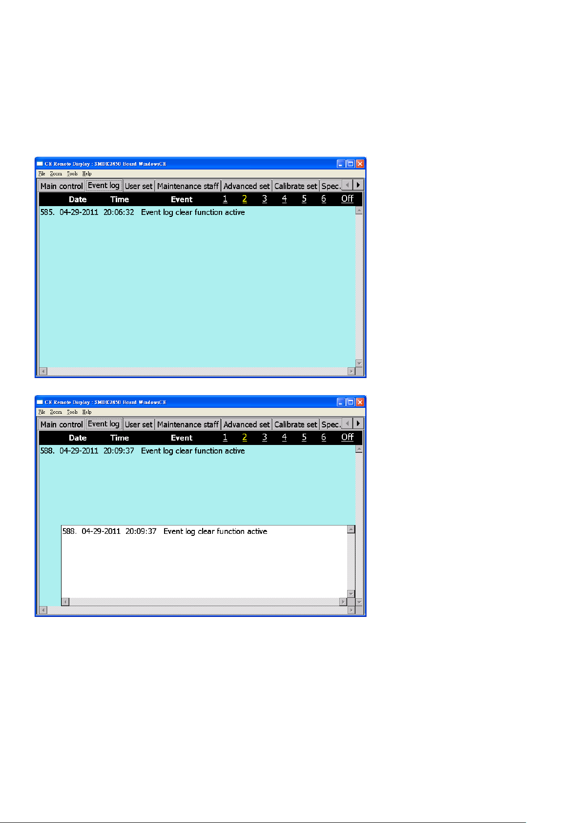
3-2-2 Event log
Up to 2400 events with time in total can be recorded on 6 pages shown as Fig.3-2-2-1. These are helpful for
maintenance engineers to find root causes and solve issues fast.
More functions:
(1) PIP (Picture in picture) event log Different events are shown in separate windows as in Fig.3-2-2-2.
(2) Logs can be exported to a portable disk.
(3) Logs are erasable.
Fig. 3-2-2-1
Fig. 3-2-2-2
Page 10
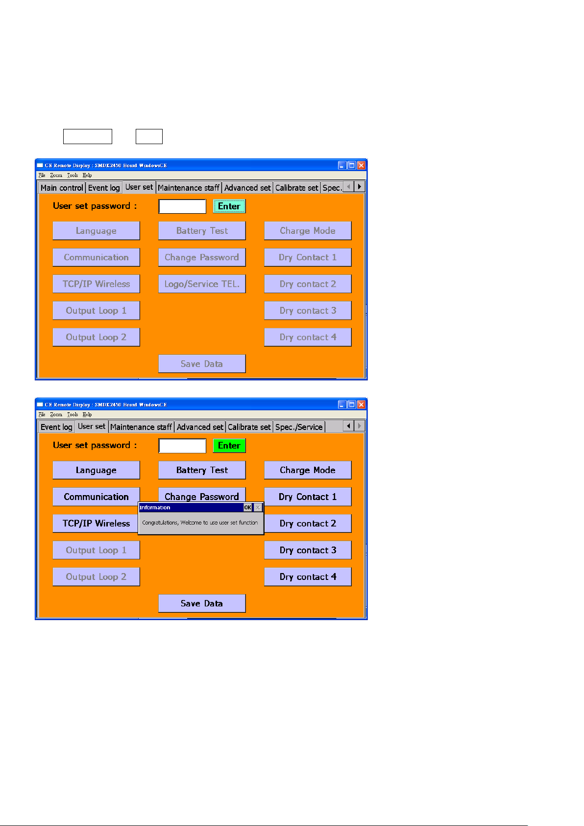
3-2-3 User set
User settings are available for end users to set/select language, battery test, charging mode,
communication mode, password, dry contact programming, brand name/ hotline shown as Fig. 3-2-3-1.
Password is required for access to this function and the default password is 000000. Successful access is
shown as Fig. 3-2-3-2.
Press Save Data and Enter buttons to avoid being reset by other people.
Fig. 3-2-3-1
Fig. 3-2-3-2
Page 11
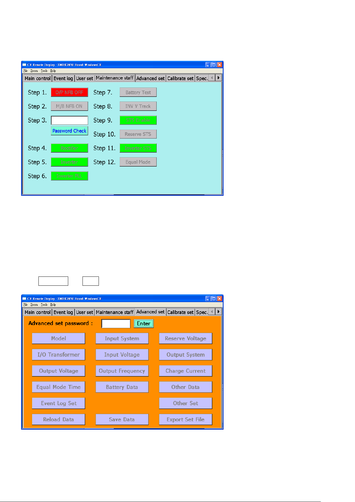
3-2-4 Maintenance staff
This function is only for professionals or qualified technicians. Professionals or qualified technicians will use
the information to find the fault root causes and solve issues timely. Operations are shown as Fig. 3-2-4-1.
Fig. 3-2-4-1
3-2-5 Advanced set
Advanced settings are available for professionals to set parameters such as model, input system, reserve
voltage, I/O transformer, input voltage, output system, output voltage, output frequency, charge current,
equalization mode time, battery data, other data, event log set, other set, reload data, save data, export set
file shown as Fig. 3-2-5-1.
Contact the manufacturer for advanced set password. This password is automatically changed every year.
Press Save Data and Enter buttons to avoid being reset by other people.
Fig. 3-2-5-1
Page 12

3-2-6 Calibrate set
Calibration settings are available for professionals to set voltage, current and temperature, etc shown as Fig.
3-2-6-1.
This function requires an advanced set password.
Press Save Data and Enter buttons to avoid being reset by other people.
Fig. 3-2-6-1
3-2-7 Spec./Service
This function display specification details and service information shown as Fig. 3-2-7-1.
Fig. 3-2-7-1
Page 13

4. Fixation and Installation
4-1 Fixation
4-1-1 Transportation
(1) Fig. 4-1-1a and Fig. 4-1-1b represent the packing.
(2) UPS should be placed in the way indicated by the arrow on the carton.
(3) In order to avoid danger during transportation, UPS or battery packs should be fastened tightly by ropes
and placed in the center of truck front end as Fig. 4-1-1c illustrates.
(4) Do not unpack the UPS during transportation.
(5) Exposing the UPS and the battery pack to liquids (including rain) is strictly prohibited.
(6) The UPS and the battery pack should not be exposed to any rigid external mechanical force, including
but not limited to pushing, punching or dropping.
(7) Moving UPS or battery packs requires forklifts or cranes as Fig. 4-1-1d and Fig. 4-1-1e illustrate.
(8) Elevators can carry UPS or battery packs. Check elevator limits for loading weights and volumes before
carrying.
Front View
Side View
Fig. 4-1-1a Fig. 4-1-1b
Page 14

U.P.S
d
Fig. 4-1-1c
Fig. 4-1-1
Fig. 4-1-1e
Page 15

4-1-2 Unpacking
Unscrew
Unscrew
(1) Cut off packing ropes and take out packing coverings as Fig. 4-1-2a, 4-1-2b and 4-1-2c illustrate.
(2) Unwrap PE coating.
(3) Unscrew screws of L fixers screwed on the pallet as Fig. 4-1-2d and 4-1-2e illustrate.
(4) Follow the arrow marks to unload the UPS as Fig. 4-1-2 illustrates.
Fig. 4-1-2a Fig. 4-1-2b Fig. 4-1-2c
Fig. 4-1-2d Fig. 4-1-2e
Fig. 4-1-2f
Page 16

4-1-3 Placement and Environment
15cm 15cm
50cm
50cm
90cm
door
Top View
DS 160KC33 II
34873
(1) A UPS should be placed in a clean and air conditioned environment and with ambient temperature
between 0℃ and +28℃. The operation temperature ranging from 10℃ to +25℃ is the best.
(2) UPS can’t be closely placed against or surrounded by walls or other objects as it would prevent from
good ventilation. An exhaust is in a rear of the UPS shown as Fig. 4-1-3a.
(3) Make room for opening the door of the UPS cabinet. For ventilation and maintenance purposes the
distances to walls or objects should be at least as shown in Fig. 4-1-3b and Fig.4-1-3c.
(4) The BTU values for DS-C33 II series shown as table 4-1-3d.
(5) The chamber for UPS placement should be sufficiently lit and equipped with an emergency fire
extinction system.
Fig. 4-1-3a Fig. 4-1-3b Fig. 4-1-3c
Table 4-1-3d BTU Values
Model BTU
DS 10KC33 II 3542
DS 15KC33 II 5313
DS 20KC33 II 6539
DS 30KC33 II 9808
DS 45KC33 II 13486
DS 60KC33 II 16347
DS 80KC33 II 21796
DS 100KC33 II 24520
DS 120KC33 II 29424
DS 200KC33 II 43592
Page 17

4-1-4 Outline and Dimension
10 / 15 / 20 / 30K 120V / 208V & 220V / 380V Models
Page 18

45 / 60K 120V / 208V Models
45 / 60 / 80 / 100 / 120K 220V / 380V Models
Page 19

80 / 100 / 120K 120V / 208V Models
Page 20

160 / 200K 220V / 380V Models
Page 21

4-2 Installation
208Vac,
208Vac,
220 / 380V
113A
3P / 125A
68A
3P / 75A
117.7A
4-2-1 UPS Input / Output Specifications
Frequency Topology Voltage
Input 50 / 60Hz 3p3w and PE 220Vac, 380Vac
3p4w and PE 110 / 190Vac, 115 / 200Vac, 120 /
127 / 220Vac, 220 / 380Vac, 230 / 400Vac,
240 / 415Vac, 254 / 440Vac
Output 50 / 60Hz 3p3w and PE 220Vac, 380Vac
3p4w and PE 110 / 190Vac, 115 / 200Vac, 120 /
127 / 220Vac, 220 / 380Vac, 230 / 400Vac,
240 / 415Vac, 254 / 440Vac
Table 4-2-1 Input / Output NFB Specifications
Capacity Voltage Max Input
Current
10KVA
15KVA
20KVA
30KVA
40KVA
45KVA
120 / 208V 43A 3P / 50A 28A 3P / 30A 48.5A
220 / 380V 27A 3P / 30A 14A 3P / 15A 24.2A
120 / 208V 64A 3P / 75A 42A 3P / 50A 72.7A
220 / 380V 39A 3P / 40A 23A 3P / 30A 39.8A
120 / 208V 84A 3P / 100A 56A 3P / 60A 96.9A
220 / 380V 49A 3P / 50A 28A 3P / 30A 48.4A
120 / 208V 124A 3P / 125A 83A 3P / 100A 143.7A
220 / 380V 74A 3P / 75A 45A 3P / 50A 77.9A
120 / 208V 167A 3P / 200A 111A 3P / 125A 192.2A
220 / 380V 101A 3P / 125A 61A 3P / 75A 105.6A
120 / 208V 187A 3P / 200A 124A 3P / 125A 214.7A
Input
NFB
Max Output
Current
Output NFB Max Neutral
Line Current
50KVA
60KVA
80KVA
100KVA
120KVA
160KVA 220 / 380V 389A 3P / 400A 242A 3P / 250A 419.1A
200KVA 220 / 380V 491A 3P / 500A 303A 3P / 350A 524.8A
120 / 208V 207A 3P / 225A 139A 3P / 150A 240.7A
220 / 380V 124A 3P / 125A 74A 3P / 75A 128.1A
120 / 208V 247A 3P / 250A 167A 3P / 175A 289.2A
220 / 380V 149A 3P / 150A 91A 3P / 100A 157.6A
120 / 208V 328A 3P / 350A 222A 3P / 225A 384.5A
220 / 380V 196A 3P / 200A 121A 3P / 125A 209.5A
120 / 208V 399A 3P / 400A 278A 3P / 300A 481.5A
220 / 380V 244A 3P / 250A 149A 3P / 150A 258A
120 / 208V 491A 3P / 500A 333A 3P / 350A 576.7A
220 / 380V 294A 3P / 300A 182A 3P / 200A 315.2A
Page 22

4-2-2 Cable Specifications
600V PVC Insulated Hard Copper Stranded Wire Safe Current Table (60℃ Insulation, Ambient Temperature
under 30℃)
Type
Sectional Area
2)
(mm
Number of
Strands/
Diameter
Safe Current
Sectional Area
2)
(mm
Number of
Strands/
Diameter
Safe Current
3.5 7 / 0.8 37 80 19 / 2.3 257
5.5 7 / 1.0 49 100 19 / 2.6 298
8 7 / 1.2 61 125 19 / 2.9 344
Hard
Copper
Strand
Wire
14 7 / 1.6 88 150 37 / 2.3 395
22 7 / 2.0 115 200 37 / 2.6 469
30 7 / 2.3 139 250 61 / 2.3 556
38 7 / 2.6 162 325 61 / 2.6 650
50 19 / 1.8 190 400 61 / 2.9 745
60 19 / 2.0 217 500 61 / 3.2 842
Temperature and current allowance values are not applicable to UL certified cables. Use of UL certified
cables should be based on cable specifications for temperature and current limits.
4-2-3 Cable Diameter
Table 4-2-3-1 Specifications for AC Input and Output and DC Battery Cables
Capacity Voltage Input (mm
10KVA
15KVA
20KVA
30KVA
40KVA
45KVA
50KVA
60KVA
80KVA
100KVA
120KVA
120 / 208V 8 5.5 8 2.0 14
220 / 380V 5.5 3.5 3.5 1.6 3.5
120 / 208V 14 8 22 5.5 22
220 / 380V 8 3.5 5.5 2.0 8
120 / 208V 22 14 30 5.5 30
220 / 380V 14 5.5 8 2.0 14
120 / 208V 38 22 50 8 50
220 / 380V 22 8 22 5.5 22
120 / 208V 60 38 80 8
220 / 380V 30 14 30 8
120 / 208V 80 38 100 8
220 / 380V 38 14 38 8
120 / 208V 100 50 125 14
220 / 380V 38 22 38 8
120 / 208V 125 60 150 14
220 / 380V 50 22 60 8
120 / 208V 200 100 250 14
220 / 380V 80 38 100 14
120 / 208V 250 150 325 22
220 / 380V 125 50 125 14
120 / 208V 325 200 400 22
220 / 380V 150 80 150 14
2
) Output (mm2) Neutral (mm2) PE (mm2) Battery(mm2)
30
38
50
60
100
125
150
160KVA 220 / 380V 250 125 250 22 250
200KVA 220 / 380V 325 150 400 22 352
Page 23

4-2-4 Terminal Definitions
(1) I/R : Rectifier Input R Phase
(2) I/S : Rectifier Input S Phase
(3) I/T : Rectifier Input T Phase
(4) I/N : Input Neutral Line
(5) I2/R : Slave UPS Input R Phase (from slave UPS input R phase for paralleling system)
(6) I2/S : Slave UPS Input S Phase (from slave UPS input S phase for paralleling system)
(7) I2/T : Slave UPS Input T Phase (from slave UPS input T phase for paralleling system)
(8) BP/R : Bypass Input R Phase
(9) BP/S : Bypass Input S Phase
(10) BP/T : Bypass Input T Phase
(11) BP/N : Bypass Input Neutral Line
(12) O/N : Output Neutral Line
(13) O/R : Output R Phase
(14) O/S : Output S Phase
(15) O/T : Output T Phase
(16) B+ : Battery Input Anode
(17) G : Grounding
(18) B- : Battery Input Cathode
4-2-5 Wiring Notices
Battery
(1) For safety, professional engineers should put on isolated gloves, use tools with isolated handles. It is
recommended that two or more engineers are working on wiring the batteries.
(2) Check if batteries are well grounded and make sure your limbs are dry before you perform battery
disconnection.
(3) Disconnect UPS and batteries (switch off the battery breaker and unplug the battery connector) and
then disconnect cables of batteries on every layer.
(4) During battery disconnection, do not touch neighboring batteries while processing cables or plates of
batteries in order not to cause short circuit.
(5) During battery connection, finish connecting batteries on each layer firstly and then interconnect the
battery layers. Finally connect the battery connector to the battery breaker.
(6) Check terminal voltage and polarity of the batteries and the UPS battery input.
Check the following items after wiring setup:
(1) Every terminal is correctly connected.
(2) PE cable is correctly grounded.
(3) Every screw is tightly screwed.
(4) All switches should stay off (at off position).
(5) Output power distribution panel is not short circuited.
(6) Battery terminals and polarities are correctly connected.
Page 24

4-2-6 Terminals
10 / 15 / 20 / 30K 120V / 208V & 220V / 380V Models
Master / Slave UPS
I/R I/S I/T
I/N
I2/R I2/S I2/T BP/R BP/S BP/T BP/N O/N O/R O/S O/T B+ G B-
45 / 60K 120V / 208V Models
45 / 60 / 80 / 100/ 120K 220V / 380V Models
Master UPS
I/R I/S I/T B+ G BI/N
I2/R I2/S I2/T BP/R BP/S BP/T BP/N O/N O/R O/S O/T
Slave UPS
I/R I/S I/T B+ G BI/N
I2/N BP/N O/N BP/R BP/S BP/T O/R O/S O/T
Page 25

80 / 100 / 120K 120V / 208V Models
Slave UPS
B+ G B-
BP/R BP/S BP/T BP/N O/N O/R O/S O/T
I/R I/S I/T I/N
Page 26

5. Operation Procedures
5-1 Power-on
5-1-1 Initial Power-on Procedures
(1) Switches
BAT Switch: for switching on/off batteries.
SPS Switch: for switching on/off the power board.
S1 Switch: for switching on/off the second AC mains power or the bypass of the model with an input
transformer.
S2 Switch: for switching on/off the primary AC mains po w e r.
S3 Switch: for switching on/off the output
S4 Switch: for switching on/off the manual bypass during maintenance.
(2) Input Phase Sequence Tes t
(3)
Firstly, turn on the power distribution panel and then check each terminal voltage with a multi-meter and
input phase sequence with a three-phase sequence detector. If the phase sequence is correct, continue the
next procedure. If the sequence is reverse, turn off the AC mains and exchange S and T phase input cables,
and turn on the AC mains. Proceed with the next procedure if the phase sequence is correct.
(4) Initial power-on
Switch off the load switch and disconnect all cables from UPS to the load. Follow the below procedures:
(a) Turn on the battery cabinet switch (battery fuse)
(b) Turn on the UPS battery switch
(c) Turn on the SPS power board switch (and wait till HMI control panel program finishes)
(d) Turn on the S1 / S2 / S3 switches
(e) Press the Inverter ON button on the HMI control panel
(f) Press the Ye s button in the pop-up window (UPS operation mode changes from bypass to inverter, and
a dialogue window pops up for this status.)
Finally, check the terminals of O/R, O/S and O/T for AC voltages and frequencies and terminals of B+ and Bfor DC voltages are correct. Operation is shown as Fig. 5-1-1:
Page 27

5-1-2 Normal Power-on Procedures
Initial Power-on Procedures:
Switch on Switch off
Switch on Switch off
SPS
S1
Power-off Proce dures:
Inverter status button
becomes green after
about 50 seconds
Bypass (Reserve) status button
becomes green
Switch on
Switch on
Switch off
Switch off
Switch on
*
S3
Switch on Switch off
S2
BAT
Switch off
Press Inverter ON
Press Yes
Press Inverter OFF
Press Yes
When the initial power-on procedure is done and the UPS is turned on. Press Inverter ON button on the
HMI control panel and Yes button on the pop-up window to restart the UPS. It will be turned on after 3
minutes.
*) for 10K~30KVA models, fuses must be installed before the initial power-on operation.
Fig. 5-1-1 UPS Power-on/off Workflow
Page 28

5-2 Power-off
5-2-1 Normal Power-off Procedures
Press Inverter OFF button on the HMI control panel and Yes button on the pop-up window to shut down
the UPS. UPS operation mode changes from inverter to bypass, and a dialogue window pops up for this
status.
5-2-2 Complete Power-off Procedures
Follow Fig. 5-1-1.
5-3 Maintenance Bypass
5-3-1 Maintenance Bypass Procedures
Follow Fig. 5-3.
5-3-2 DS10KC33 / 15KC33 II Inbuilt Battery Replacement Procedures
(1) Transferring to bypass mode
Follow Fig. 5-3 to transfer to bypass mode.
(2) Replacing old batteries
Remove the rear panel, battery fixers (plates) and disconnect the cables. Rewire the new batteries the same
way the old batteries have been wired. Check voltage and polarity after new batteries have been installed.
(3) Restarting the UPS
Follow Fig. 5-3 to transfer to inverter mode.
5-4 Resumption from Maintenance Procedures
Follow Fig. 5-3.
5-5 Emergency Power Off
EPO (Emergency Power Off) is a device for an accident or emergent power cutoff under abnormal or
unexpected circumstances. EPO makes:
(1) the inverter shut down;
(2) STS (Static Transfer Switch) trip and cut the system output.
(3) RCM (Rectifier Charging Module) stop.
EPO activation and deactivation events and times will be recorded. Communication stays normal during
EPO is active. Press EPO button again and Inverter OFF button on the HMI control panel and Yes button on
the pop-up window and the UPS will resume and operate in bypass mode, and then transfer back to
inverter mode after 3 minutes.
Page 29

Fig. 5-3 Maintenance Bypass Workflow
*) for 10K~30KVA models, fuses must be installed before the initial power-on operation.
Page 30

5-6 Dry Contact Communication
10
BACKUP MODE_NC
FAN FAULT_COM
11
INV ON_NO
FAN FA U LT _ N C
12
INV ON_COM
FUSE FAULT_NO
24
UPS OVERLOAD_COM
FUNCTION RELAY3_NO
25
UPS OVERLOAD_NC
FUNCTION RELAY3_COM
26
SYN. AC FAIL_NO
FUNCTION RELAY3_NC
(1) PCB-3308 Dry contact layout shown as Fig. 5-7-1.
(2) PCB-3308 Dry contact function definitions listed in Table 5-7-2.
Fig. 5-7-1 Dry Contact Layout
Contact CN2 CN3
1 +12V USER0 +12V
2 INV STS_NO EXT. SHUTDOWN
3 INV STS_COM USER1 +12V
4 INV STS_NC EX T. EP O
5 BAT LOW_NO +12V
6 BAT LOW_COM ROLATION ERROR_NO
7 BAT LOW_NC ROLATION ERROR_COM
8 BACKUP MODE_NO ROLATION ERROR_NC
9 BACKUP MODE_COM FAN FAULT_ NO
13 INV ON_NC FUSE FAULT_COM
14 UPS FAULT_NO FUSE FAULT_NC
15 UPS FAULT_COM FUNCTION RELAY1_NO
16 UPS FAULT_NC FUNCTION RELAY1_COM
17 RECIFIER AC FAIL_NO FUNCTION RELAY1_NC
18 RECIFIER AC FAIL_COM COMPOSITE FAULT_NO
19 RECIFIER AC FAIL_NC COMPOSITE FAULT_COM
20 RESERVE FAIL_NO COMPOSITE FAULT_NC
21 RESERVE FAIL_COM FUNCTION RELAY2_NO
22 RESERVE FAIL_NC FUNCTION RELAY2_COM
23 UPS OVERLOAD_NO FUNCTION RELAY2_NC
27 SYN. AC FAIL_COM FUNCTION RELAY4_NO
28 SYN. AC FAIL_NC FUNCTION RELAY4_COM
29 RCM SHUTDOWN_NO FUNCTION RELAY4_NC
30 RCM SHUTDOWN_COM SPEAKER1
31 RCM SHUTDOWN_NC SPEAKER2
32 GND GND
Table 5-7-2 Dry Contact Signal Definitions
Page 31

6. Maintenance and Storage
(1) Clean the UPS placement chamber and the UPS itself from dust every 6 months.
(2) Recharge and discharge batteries every 3 months to maintain their lifetime.
(3) Pay attention to the temperature and humidity of the chamber.
(4) When storing a UPS, disconnect all cables (take out the fuses or batteries for battery-inbuilt models)
and wrap the UPS with PE coating.
(5) If after restarting the UPS that has been returned to operation from storage, the time or date is
incorrect on the HMI display panel, change the Lithium battery.
7. Troubleshooting
Deal with issues relying on events, messages or indications of icons or pop-up windows on the HMI display
panel shown as below. Contact technicians or professionals to assist in solving issues.
Page 32

8. Specifications
Model
Capacity 10KVA 15KVA 20KVA 30KVA 45KVA 60KVA 80KVA 100KVA 120KVA 160KVA 200KVA
Rated Power 8KW 12KW 16KW 24KW 36KW 48KW 64KW 80KW 96KW 128KW 160KW
Power Factor 0.8
Phase 3 Phase 3 Wire or 3 Phase 4 Wire and PE
Voltage Range 10K~120K: 120V/208 or 220V/380V ±20%; 160K~200K: 220V/380V ±20%
Frequency Range 50Hz / 60Hz ±5Hz Auto Sensing
Rectification 6 Pulse (Standard) / 12 Pulse (Optional)
Rectifier Efficiency >97%
Inverter Efficiency >88%
Phase 3 Phase 3 Wire or 3 Phase 4 Wire and PE
Volta ge 120V/208V or 220V/380V
Stabilization ±1%
Transient 90% Resumption after 4 Cycles
Overload Capacity
Inverter Topology IGBT Design, DSP Control, 20KHz PWM Sine Wave
Frequency 50Hz / 60Hz
Frequency Stabilization ±0.1%
Phase Lock Range ±5Hz
Phase Unlock Range >±5Hz
Phase Relock Range ±3Hz
Waveform Sine Wave
Crest Factor 3:1
THD <3% for Linear Load
Transfer
Cold Start Transfer 2 Level Voltage Transfer
Transfer Time
Efficiency >99%
Volta ge DC220V / DC410V DC410V DC435V
Current 1.5~10A 3~20A 5~30A 15~50A
Time 100% discharged and then recharged to 90% in 8 hours (depending on battery specifications)
DS10K
C33 II
DS15K
C33 II
as the voltage and the frequency of the inverter and the utility are synchronized.
DS20K
C33 II
DS30K
C33 II
>101% ~ 124% Transferred to bypass after 30 minutes
>125% ~ 150% Transferred to bypass after 10 minutes
>150% Transferred to bypass after 1 minute
Static Transfer Switch
UPS transfers from bypass mode to inverter mode
DS45K
C33 II
Input
Output
Bypass mode to inverter mode 0ms
Inverter mode to bypass mode 0ms
Charger
DS60K
C33 II
DS80K
C33 II
DS100K
C33 II
DS120K
C33 II
DS160K
C33 II
DS200K
C33 II
* Specifications are subject to change without notice.
Page 33

Model
Battery Configuration
Backup Time Depends on overall battery capacity
Noise <60dB
Operating Temperature 0~40℃
Storage Temperature -25℃~55℃
Storage Altitude <10000M
Operating Altitude <3500M
Relative Humidity 90% Non Condensing
Width 530 530 530 530 810 810 810 810 810
Depth 869 869 869 869 810 810 810 810 810
Height 1010 1010 1010 1010 1900 1900 1900 1900 1900
Width 580 580 580 580 920 920 920 920 920
Depth 900 900 900 900 920 920 920 920 920
Height 1200 1200 1200 1200 2165 2165 2165 2165 2165
DS10K
C33 II
DS15K
C33 II
DS20K
C33 II
DC192V (12V × 16pcs)
DC360V (12V × 30pcs)
DS30K
C33 II
Physical Dimensions
DS45K
C33 II
Packing Dimensions
DS60K
C33 II
DS80K
C33 II
DS100K
C33 II
(12V × 30pcs)
DS120K
C33 II
DC360V
* Specifications are subject to change without notice.
DS160K
C33 II
(12V × 32pcs)
TBD
TBD
TBD
TBD
TBD
TBD
DS200K
C33 II
DC384V
TBD
TBD
TBD
TBD
TBD
TBD
Page 34

9. Contact Information
OPTI-UPS USA:
Tel: +1-909-869-5700
Fax: +1-909-869-5730
info@opti-ups.com
www.opti-ups.com
OPTI-UPS Europe:
Tel: +31-40-401-50-00
Tel: +31-40-262-80-57
Fax: +31-40-254-60-06
eu@opti-ups.com
www.opti-ups.com
OPTI-UPS Middle East:
Tel: +9714-8819-838
Fax: +9714-8819-938
mea@opti-ups.com
www.opti-ups.com
OPTI-UPS Australia & New Zealand:
Tel: +64-9-441-6470
Fax: +64-9-441-6490
aunz@opti-ups.com
www.opti-ups.com
OPTI-UPS Germany:
Tel : +49-7071-5495-148
Fax: +49-7071-5495-149
germany@opti-ups.com
www.opti-ups.com
OPTI-UPS Japan:
Tel: +81-3-3629-5782
Fax: +81-3-5682-0652
japan@opti-ups.com
www.opti-ups.com
OPTI-UPS Asia:
Tel: +886-2-2246-7272
Fax: +886-2-2246-7312
info@opti-ups.com.tw
www.opti-ups.com.tw
 Loading...