

Page 1

OPTI-UPS
User’s Guide
Durable Series
Models DS-D33
www.opti-ups.com
Page 2

Contents Page
1. SYSTEM OVERVIEW
1.1. Construction of the UPS
1.2. Features and
1.3. Rectifier
1.4.
Inv
1.5. Static Switch
erter
Advantages......................................................................
...............................................................................................
.................................................................................................
......................................................................................
1.6. Maintenance Bypass Switch
1.7. Dimension & Drawings
1.8. Front Panel
.........................................................................................
2. TECHNICAL SPECIFICATION
..............................................................................
......................................................................
..............................................................
.....................................................................
...................................................................
2.1. 20KVA ~ 60KVA UPS 3–Phase Input / 3-Phase
2.2. 80KVA ~ 160KVA UPS 3–Phase Input / 3-Phase
2.3. 20KVA ~ 50KVA UPS 3–Phase Input / 1-Phase
3. INSTALLATION
3.1. Site & Environment
3.2.
Unp
ack
3.3. Cable Selection
3.4. Terminal
4. OPERATIONS
4.1. Switch on Procedure
4.2. Shutdown Procedure
4.3. From Inverter to Bypass Procedure
4.4. From Bypass to Inverter Procedure
5. LCD
DISPLAY ..............................................................................................
5.1. Menu 0 – Main
5.2. Menu 1 – Select Menu
5.3. Menu 2 – Status / Warning
5.4. Menu 3 – Real Time Data
...........................................................................................
Consideration ......................................................
ing ............................................................................................
....................................................................................
Conn
ect
ion ............................................................................
...............................................................................................
............................................................................
............................................................................
.....................................................
.....................................................
Menu...........................................................................
.........................................................................
Menu.........................................................
Menu ..........................................................
1-10
1-11
1-12
1-17
Output ......................
Output ....................
Output ......................
1-1
1-1
1-5
1-8
1-9
2-1
2-1
2-4
2-7
3-1
3-1
3-4
3-5
3-7
4-1
4-1
4-2
4-3
4-4
5-1
5-1
5-2
5-3
5-4
Page 3

Contents Page
5.5. Menu 4 – Historical Event
5.6. Menu 5 – Parameter Setting
5.7. Menu 6 – Rectifier Data Menu
5.8. Menu 7 – Output Data Menu
5.9. Menu 8 – Other Data Menu
5.10. Menu 9 – Reserve Data
5.11. Menu 10 – Boost Charge Setting
5.12. Menu 11 – Data Time Setting
5.13. Menu 12 – Other Setting
6. INTERFACE C
6.1. Dry Contacts
6.2. External
6.3. DB9
7.
OPTIONS .......................................................................................................
7.1. Battery Cabinet
ONNECTIONS .....................................................................
........................................................................................
Shutdown ...............................................................................
Conn
ection
...................................................................................
....................................................................................
7.2. Emergent Stop Switch
7.3. Remote Control Panel –
7.4. Software for PC Monitoring –
7.5. Auto Dialing Module –
7.6. Battery Monitoring Module -
8.
REDUNDANCY ............................................................................................
8.1. Serial Redundancy
9.
HELP..............................................................................................................
...............................................................................
Menu .........................................................
Menu.......................................................
............................................................
...............................................................
.................................................................
Menu..............................................................
Menu ...............................................
Menu ..................................................
Menu..........................................................
..........................................................................
UPSCAN™
UPSCOM™
UPSCALL™
DCMAN™
...................................................
.........................................
..................................................
............................................
5-5
5-6
5-7
5-8
5-8
5-9
5-9
5-11
5-12
6-1
6-1
6-3
6-3
7-1
7-1
7-2
7-2
7-2
7-3
7-3
8-1
8-1
9-1
Page 4

CAUTION !
☆ Hazardous voltage exits inside the UPS (includes the connection
terminals), cable connection and maintenance should be done by
professional or qualified personnel.
☆ The UPS has its own internal battery source (battery). The output
terminals may be live even when the UPS is not connected to the
AC supply.
☆ DC capacitors are employed in this unit, hazardous voltage still
exists even when the unit is not energized. Do not touch any part
of the UPS inside.
WA RNING !
☆ Be sure to operate the UPS within the rated power of the UPS.
☆ Prevent direct exposure to direct sunlight rain or contaminating
environment.
☆ Only qualified technicians should replace the batteries. Since
batteries have high short-circuit current capacity. Mistakes in
connection or disconnection can cause severe burns or death to
servicing personnel.
Page 5
1-1
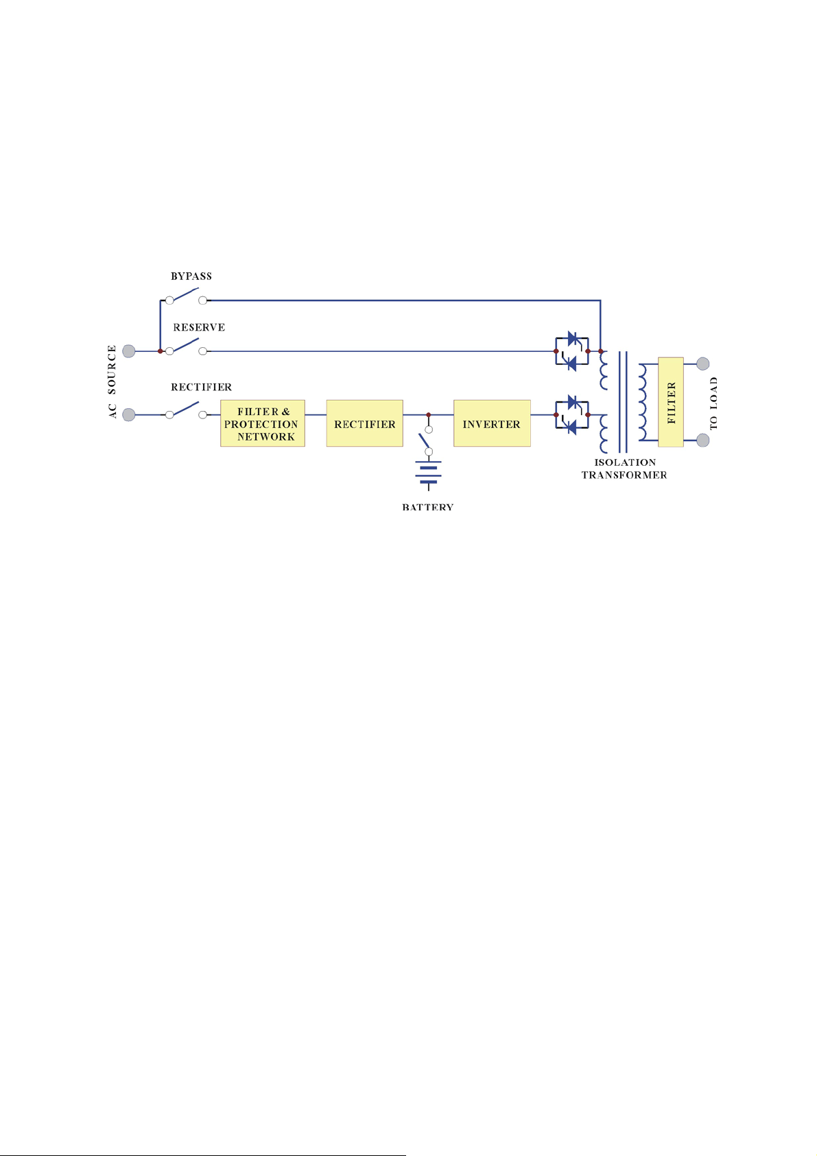
1. SYSTEM OVERVIEW
1.1. Construction of the UPS
General Topology:
The UPS system is composed of input breakers, input filter & protection network,
rectifier, battery
bank, inve
rte
r,
static switch, bypass breaker, isolation transformer
and output filter. The basic topology is shown in the diagram above. Under normal
AC mode, energy from the AC source is converted to DC power and supply to the
inverter and charge the battery to its full capacity all the time, ready to support the
output load in case of AC source failure.
Perhaps one may doubt if it is worthwhile to buy a UPS. But when you use a
calculator to add up the
dire
ct and indirect loss caused by AC failure, you will
immediately find that the money you save in 2 or 3 times of AC failure can already
compensate the cost of a UPS. Besides, the life expectancy of a UPS is at least 5 to
8 years, you may already get back the expense on the UPS within one year.
Although the principle and operation of a UPS seems simple and straightforward,
for
the requirement
a reliable and intelligent UPS makes the design and
manufacturing of a high power UPS requires advanced technology, intelligence,
experience and the most important, be c
ons
iderate to the user. Therefore we spend
years and huge investment in developing the most rugged, intelligent and reliable
UPS for the market, safe and convenient UPS for the user.
Page 6
1-2
Besides, the knowledge of choosing the best and most suitable UPS can be easy or
can be difficult, it depends on whether you know the key points or not. The most
g
obvious specification is the power, it depends on how lar
e is your load. Usually, an
allowance of 50% more power must be added to the current power you needed, both
for tolerance and future expansion. Of course you can add more than 50% if you
expect a larger increase of load in the future.
Another important point is the reliability, the prime aim of a UPS is to protect your
load, and therefore the UPS should be much more reliable than the AC source.
Those unfortunate UPS users who bought a unreliable
UPS
may suffer the
problem of frequent break down of the UPS, even more frequent than AC failure,
the cost of repairing is more the cost of the unit itself.
The last point is to choose an honest and experienced suppler who can help you
to choose the correct UPS, react promptly in case of UPS problem. Then, you can
save your money as well as buy a correct, suitable, and reliable UPS that is the
same as buy insurance to your load.
Generally, there are four different modes of operation, the NORMAL OPERATION
MODE, the BACK-UP (BATTERY) MODE, the RESERVE MODE and the
MAINTENANCE BYPASS MODE. They are explained as below.
Normal Operation Mode:
The rectifier converts the AC input to DC power to supply the inverter and charge the
battery simultaneously. All the fluctuations, surges and spikes of the AC input is
removed during AC to DC conversion, therefore the AC supplied by the inverter is
clean and stable.
Page 7
1-3
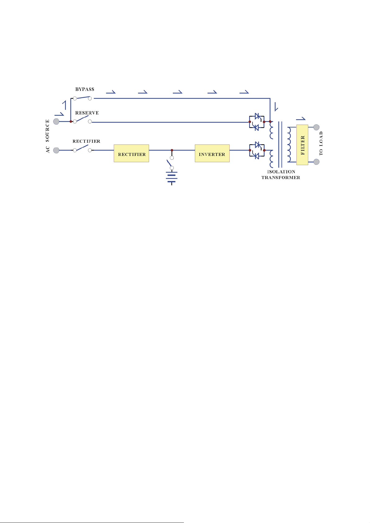
Back-up Mode:
Since the battery is connected directly to the DC bus, when the AC failure, the
battery change immediately
instead of receiving energy from the rectifier. The
from
receiver to donor, supply energy to the inverter
output AC
is not interrupted.
Therefore, the load connected to the output is protected.
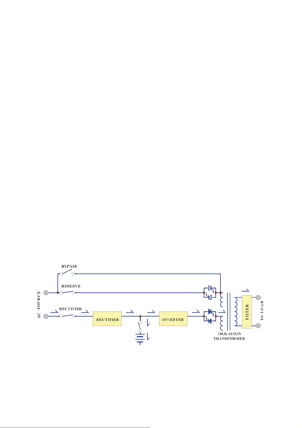
Reserve Mode:
When the inverter is in abnormal conditions, such as over temperature, short circuit,
abnormal output voltage or overloaded for a period exceed the inverter’s limit, the
inverter will automatically shutdown, in order to protect itself from damage. If the
utility power is normal, the static switch shall transfer the load to the reserve source
without interruption of AC output.
Page 8
1-4
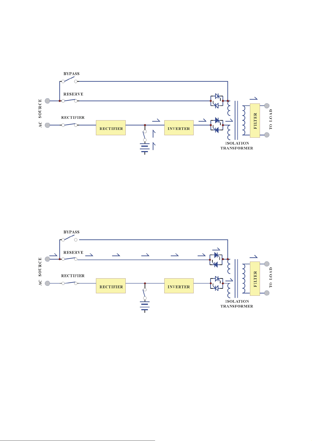
Maintenance Bypass Mode:
In case of UPS maintenance or battery replacement, and the load cannot be
interrupted, the user can turn off the inverter, close the bypass breaker and then
open the rectifier and reserve breakers. The AC output will
not be
interrupted during
manual bypass transfer procedure. Therefore maintenance bypass switch keeps
continuously power supply to the load. Electricity will not exist in UPS except the
output transformer, thus ensure the safety of service personnel.
Generally, the UPS is expected to run 24 Hours a day in normal operation mode
once it is installed, except when the utility power is fail, under overload condition,
or during maintenance.
The normal operation with battery connected can provide a clean, stable, free from
any spikes and surges, regulated and uninterruptible power to the load. Therefore,
the UPS and be regarded as a perfect AC
power source
except the back-up time
under mains failure is limited by the capacity of battery connected.
Page 9

1-5
1.2. Features and Advantages
(a) Reliable input protection: Circuit breakers is put in each individual input
loop to ensure power can continue through the other loop in case of breaker trip
caused abnormal condition in either rectifier or load.
(b) Input surge protection: MOV (surge protector) is added at the input, provide
sufficient protection to both UPS and the load from any lightning or surge
caused by neighboring large loads.
(c) EMI suppression: EMI filter is added to meet the international EMC limits,
therefore, very low
noise
is emitted and never interfere other equipment
connected to the same AC source.
(d) Ruggedness: The rectifier employ phase control technology to regulate the
DC bus voltage, so it can charge the battery directly, it is the most efficient
method to charge the battery. Besides, the component used is SCR, the
component get merits by its ruggedness under poor condition. Also, big inductor
is added at the input to avoid deforming the AC source waveform.
(e) High frequency design: The inverter uses high frequency, high efficiency
IGBT, PWM method
to conv
ert the DC power to AC power. Therefore, number
of components is fewer, in return, reliability is improved, size and weight of
UPS is reduced, then the transportation cost is cheaper, performance improved
and the acoustic noise is eliminated too.
(f) True Galvanic isolation: An isolated transformer is put at the output, can
solve the problem of
poor input
grounding and can accept a different ground
between input and output, can avoid the annoying problem of ground leakage
current and can be tied to any potential provided on site. The AC output is
isolated
under
every mode of operation. Besides, the user gets the bonus of
attenuation of common mode noise from the output isolation transformer.
Page 10

1-6
(g) P&P Modular design: The power circuit is separated into several modules
plugged into slots in
th
e
UPS,
which is easy to pull out, permit quick
maintenance and easier trouble shooting. Therefore, it can be regarded as plug
and play modules.
(h) Cold start function: the UPS can be started without AC source, that is, can
be started with battery only, because current limit circuitry is added. It can
prevent the problem of many UPS that the big inrush current blow the battery
fuse and hurts the DC capacitors when battery is connected to empty DC bus
(before the DC bus is energized).
(i) Multi-CPU design: Several CPUs are employed in the control circuit, critical
functions are designed to parallel redundancy to improve reliability. Therefore,
in case of one CPU fails the other CPUs keep on their duty and the output AC
will not be affected.
(j) Defense to mis-operation: The UPS is designed with breaker on/off sensor,
power supply sensor etc. Therefore any operational mistake made by the user
causes no harm to the UPS.
(k) Wide input range: The UPS is designed to accept extra wide input range, so
that it can work comfortable under poor AC source. Also, all the input
components used are especially selected to handle extreme high voltage and
high current.
(l) Tolerate harsh environment: Each component of the UPS is chosen with
larger safe margin to accept extreme environment, such as temperature, humidity,
attitude, shock or contamination.
(m) Intelligent charger: The UPS will automatically recharge (boost charge) the
battery every time after the battery is consumed to a voltage 2V/Cell, so that the
battery can be recovered to the full capacity as soon as possible to be ready for
the next back-up. Besides, in order to keep the battery in the best condition, the
UPS will boost charge the battery for several hours (selectable) automatically
every month. To avoid over charging the battery, Boost charge will stop when
the ambient temperature is over 35 ℃(95℉).
Page 11

1-7
(n) Intelligent battery test: Battery is tested after every boost charge of battery
(either initiated by battery discharge or by one month has elapsed) without
stopping the rectifier to prevent the risk of output AC failure in case of battery
bad. And can inform the user the battery condition, so that the user can take
action before the capacity of the battery is needed.
(o) Huge charging power: The charge power is selectable (Lo/Me/Hi) according
to Ah of the battery, and can charge up battery of more than 8Hrs back-up time
without adding extra charger.
(p) MTBF of fans is extended: Fans will slow down under light load, so that
the life expectancy of the fans are longer than it is specified.
(q) Redundant power supply: An extra power supply is connected redundantly
to supply power of the static switch, so that, there will be AC output no matter
what happen to the UPS.
(r) Intelligent interface: One remote control panel (or one PC) can monitor up to
99 UPS, all of them can be remotely switched on or off, and when any one of
them encounters emergent condition, it will warn the user immediately. All the
to
UPS status, data or commands are transmitted
external modules through 4
RS-485 ports (for long distance communication under harsh environment).
(s) Emergent stop is available: In case of hazard, for example electric shock,
fire or earthquake, the UPS can be shutdown (will have no AC at the output)
either through a switch (can be added upon request) or through smoke detector
signal (can be added upon request) to prevent further injuries or destruction.
Page 12
1-8
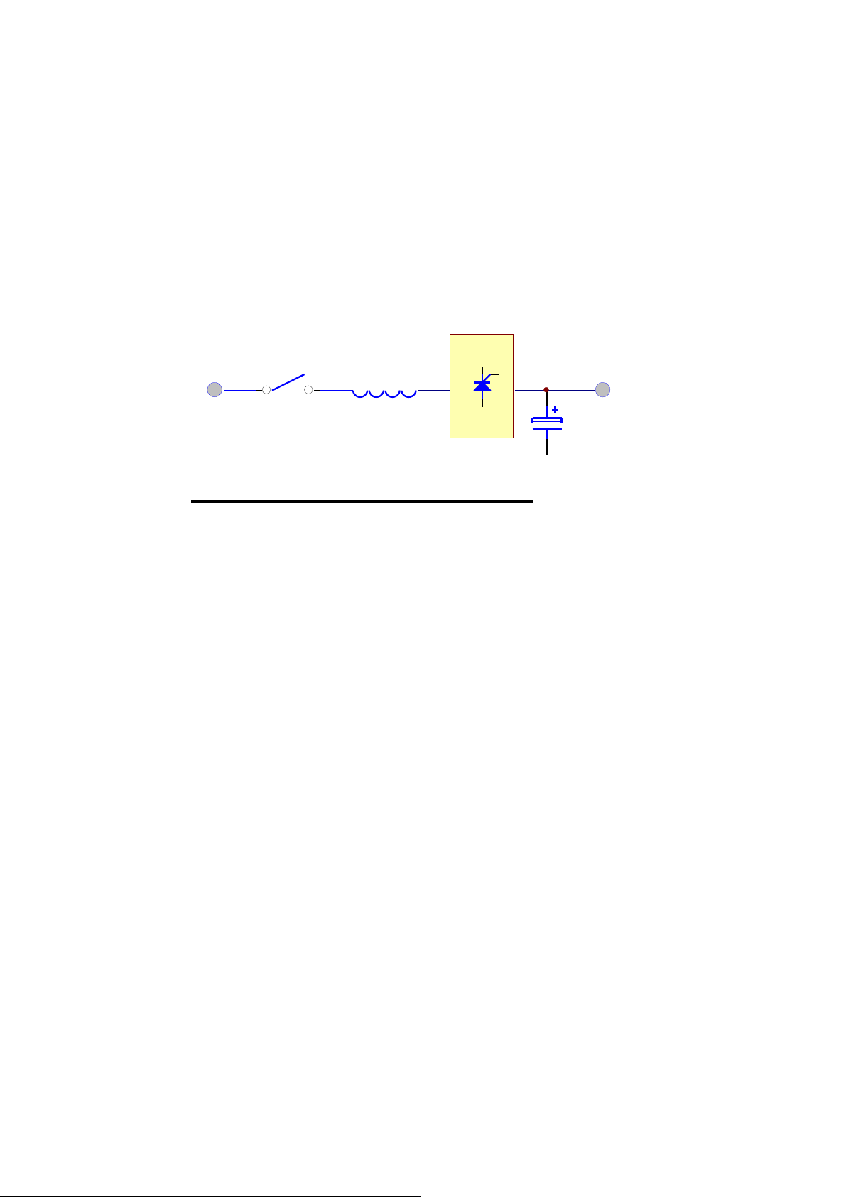
1.3. Rectifier
The main function of a rectifier is to convert the AC input to DC power, supply it to
the inverter; the inverter then converts the DC power to AC power to the load. Our
UPS use the DC power to charge the battery as well, which i
s th
e most efficient way
of charging.
AC
INPUT
6-PULS E FULL CONTROL RECTIFIER
RECTIFIER
BREAKER INDUCTOR
SCR
DC
OUTPUT
CAPACITOR
The rectifier of from 20KVA to 80KVA UPS uses 6-pulse full controlled rectifier.
An inductor is added before the rectifier to improve the power factor, smooth the
current waveform and eliminate the harmonic current as well. The control circuit
regulates the DC bus within 1%. Soft walk-in circuitry (approximately 20sec.) and
current limit circuitry is used to prevent over current or instantaneous surge current.
Extra under-voltage and over-voltage protections are added to improve reliability and
to shutdown the rectifier in case of abnormal conditions. The DC bus is adjustable to
fit different types of battery. The power component use in rectifier is especially
selected to handle extreme high voltage and high current. The rectifier is designed to
operate under wide range of AC input, from 177 to 300VAC, to fit the poor power
conditions in some area.
Page 13
1-9
PHASE SHIFT
AC
INPUT
RECTIFIER
BREAKER INDUCTOR
TRANSFORMER
SCR
SCR
DC
OUTPUT
CAPACITOR
12-PULSE FULL CONTROL RECTIFIER
In order to further improve the power factor and reduce harmonic current drawn by
the rectifier, our UPS from 100KVA and above use the 12-pulse full controlled
rectifier. The total current harmonic current can be reduced to around 15%, and
power factor is improved to over 0.8. A phase shift transformer is added to achieve
the performance. The input inductor is retained too to obtain the best result. Although
the cost is higher, it is most reliable and rugged topology. Users need not to increase
the input breaker and cable, input KVA and harmonic current drawn is minimized to
fulfill the worldwide energy saving requirements.
The harmonic current can be further lowered by adding harmonic filters (install upon
request). The total harmonic current will be around 9%.
Another alternative method to reduce the harmonic current (especially for very large
KVA UPS) is to employ 18-pulse full controlled rectifier. The total harmonic current
will be around 7%.
1.4. Inverter
DC+
AC
DC-
IGBT
INVERTER
AC
Page 14

1-10
TO LOAD
TO LOAD
The inverter is composed of IGBT, inductor, capacitor, snubber, control circuitry and
protection circuitry. It can convert the DC power from the DC bus to AC power
supply to the output load. Our UPS use IGBT technology which can switched to
frequency beyond audible range, therefore no audible noise.
Our UPS use voltage regulation circuitry to limit the voltage variation within 1%.
Also special compensation circuitry is added to eliminate the output distortion. Every
component is oversized to accept the wide DC input range (from 285 to 420VDC), so
that the output waveform remains sinusoidal throughout the range. With the aid of
dynamic feedback loop the inverter will keep a sine waveform even under non-linear
load.
We use independent inverter for each phase. Although it is more expensive, each
inverter has its independent feedback, so that the voltage is unaffected when load is
added to the adjacent phase, that is excellent voltage regulation under 100%
unbalanced load.
The IGBT is operated in its optimal condition to obtain best efficiency, so as to
minimize the electricity cost of the user.
Usually, the most frequent failure of UPS happens at the inverter, therefore we added
redundant protection circuitry
suppress the spikes and noise, use over sized and
to
protect the inverter, strong snubber is added to
high
quality components, add
semi-conductor fuse and good ventilation etc. Every step aims at a rugged, reliable
and high efficient inverter. At the same time, the inverter can sustain overload and
high peak current drawn by the load. And the MTBF must be long than one expects.
1.5. Static Switch
RESERVE
INVERTER
FILTER
RESERVE
INVERTER
FILTER
RESERVE MO DE INVERT ER MO DE
Page 15

1-11
The static switch is composed of two pairs of back-to-back connected SCR. It can
transfer the load from reserve to inverter or from inverter to reserve without dead
time at the output. Therefore, it is a very important portion of a UPS.
Detection circuitry is added to the control circuit to achieve zero dead time transfer.
Extra detection logic is employ to control when should the static switch transfer. For
example, when output is short circuited under normal mode operation, the UPS
detect the short circuit and stop the inverter after a period which the inverter can
endure,
then the static switch will not transfer to reserve to prevent tripping and
hurting the reserve breaker. But in case of overload, the UPS will stop the inverter
after a period the inverter can endue, and then transfer the load to reserve
because the
overload capability of the static switch is higher than the inverter.
Also the transfer action is determined according to the reserve-input voltage and
frequency to protect the load from supplying incorrect power to the load. At last,
there is a double check by the CPU whether the transfer is successful or not.
1.6. Maintenance Bypass Switch
Unlike other UPS, the maintenance bypass switch is already installed inside the UPS
for convenience. It should be opened under normal operation, and only closed during
maintenance. For the sake of maintenance personnel’s safety, all power supply inside
the UPS should be disconnected before touch any parts inside the UPS; therefore, the
maintenance bypass switch is a necessity to maintain AC power at the output and can
keep safe at the same time. If the bypass breaker is closed under normal operation,
the inverter will stop and the load will be automatically transferred to reserve to
prevent the inverter connect directly to the AC source. Of course, you cannot switch
on the in
verter as long as the maintenance bypass breaker is closed.
The operation of the maintenance bypass breaker is that, switch off the inverter first
then the static switch will automatically transfer the load to reserve without dead
time. Then now you can close the maintenance bypass breaker now, and then open
the reserve breaker, so that the load can get AC from the output without interruption.
Page 16

1-12
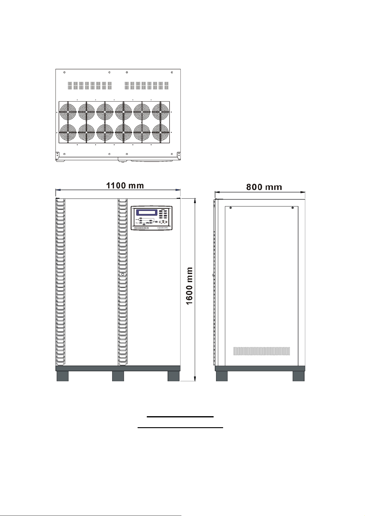
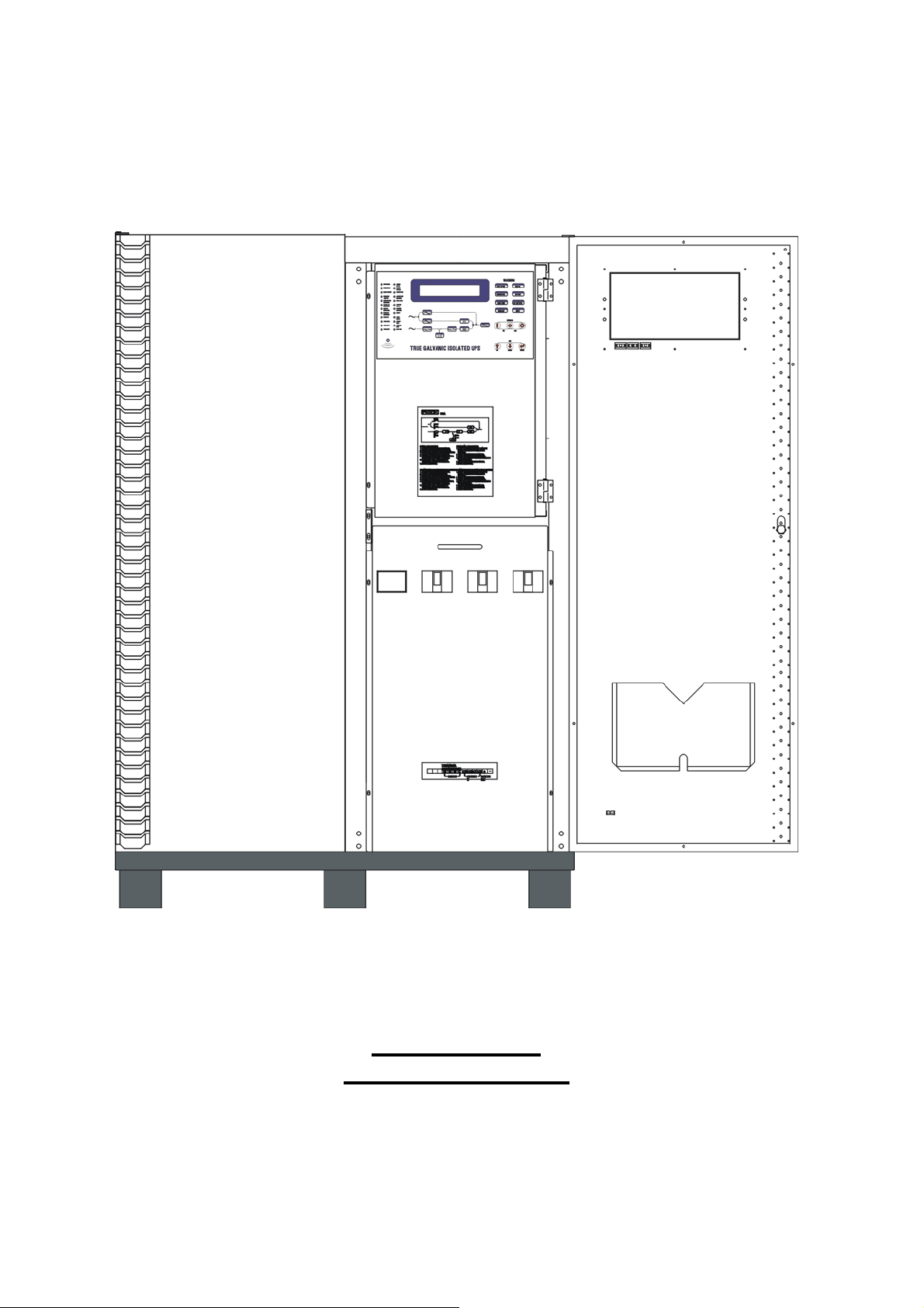
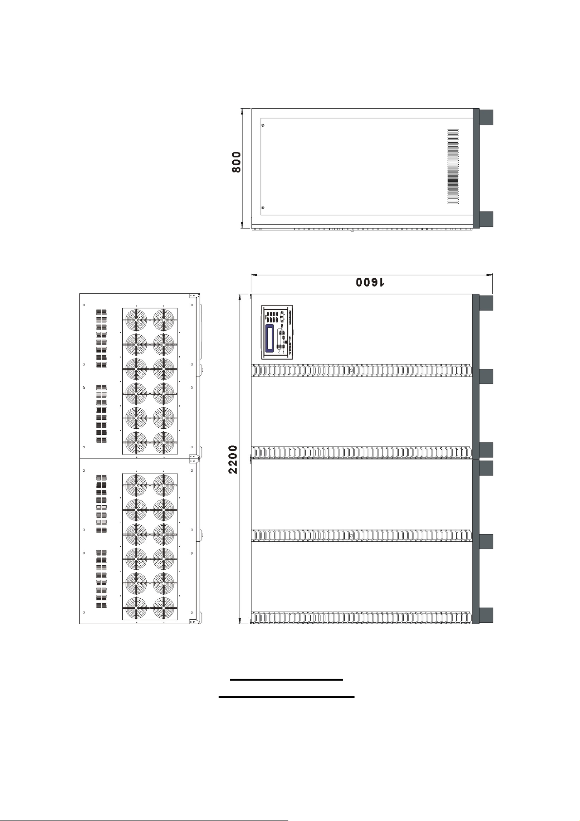
1.7. Dimension & Drawings
20KVA ~ 60KVA
OUTLINE DRAWING
Page 17
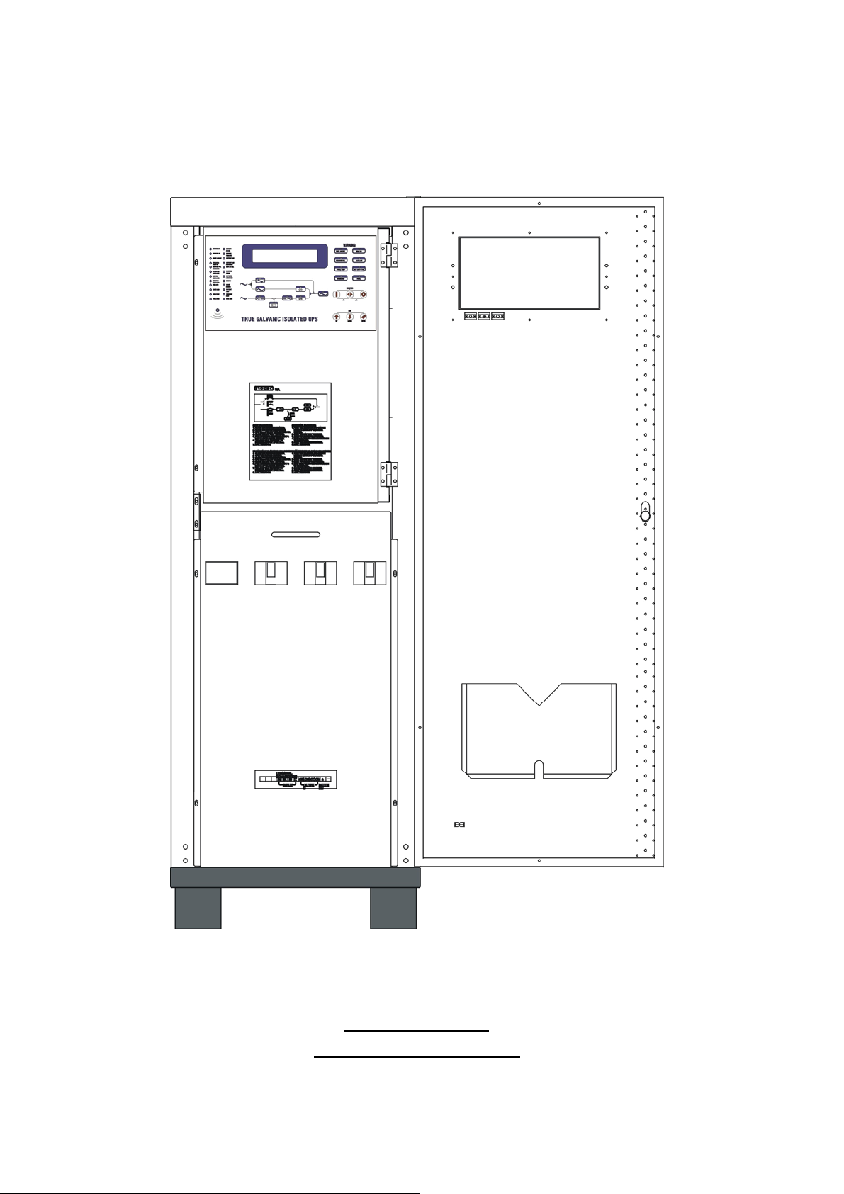
1-13
20KVA ~ 60KVA
INTERIOR DRAWING
Page 18
1-14
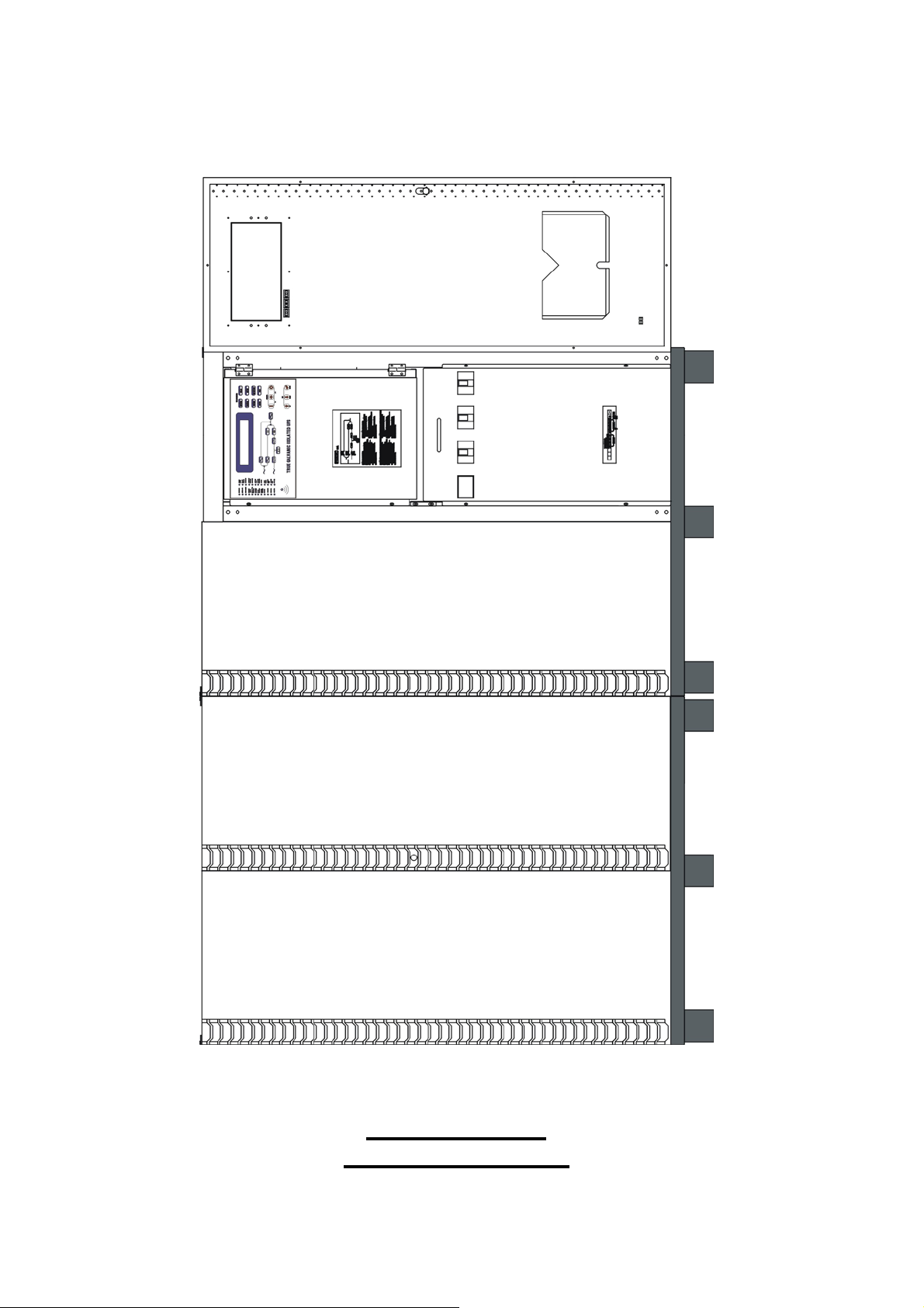
80KVA ~ 160KVA
OUTLINE DRAWING
Page 19
1-15
80KVA ~ 160KVA
INTERIOR DRAWING
Page 20
1-16
200KVA ~ 320KVA
OUTLINE DRAWING
Page 21
1-17
200KVA ~ 320KVA
INTERIOR DRAWING
Page 22
1-18
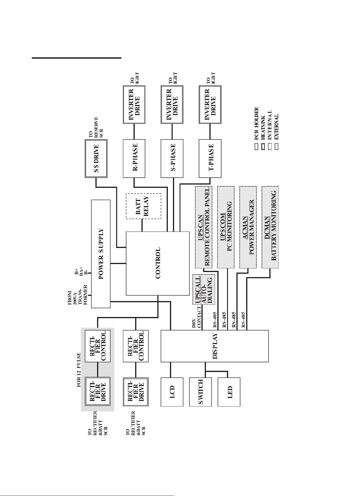
INTER-PCB DIAGRAM
Page 23
1.8.
Front Panel
1-19
~
B
A
C
INVERTER ON
INVERTER SS
SHORT CIRCUIT
FUSE/OVER
TEMP SD
INVERTER FAIL
SHUTDOWN
BYPASS ON
SHUTDOWN
HIGH DC
SHUTDOWN
OVERLOAD
SHUTDOWN
70%LOAD
110%LOAD
125%
150%LOAD
LOAD
RESERVE
AC FAIL
RESERVE
FREQ FAIL
BATTERY LOW
BATTERY LOW
SHUTDOWN
RECT AC FAIL
ROTATION
ERROR
RECTIFIER
SHUTDOWN
HIGH DC
BOOST
CHARGE
BATTERY
TEST
EM
STOP
DATA LINE
ERGENT
~
~
~
~
/
~
TRUE GALVANIC ISOLATED UPS
~
RECT AC FAIL
FAIL
RESERVE
FUSE
/
TEMP
OVERLOAD
ON
UP
WARN
INVERTER
LCD
DOWN
ING
HIGH DC
BAT
BAT LOW STOP
FAULT
OFF
LOW
Q
R
P
ENTER
D E F G H I J K L M N O
Page 24

1-20
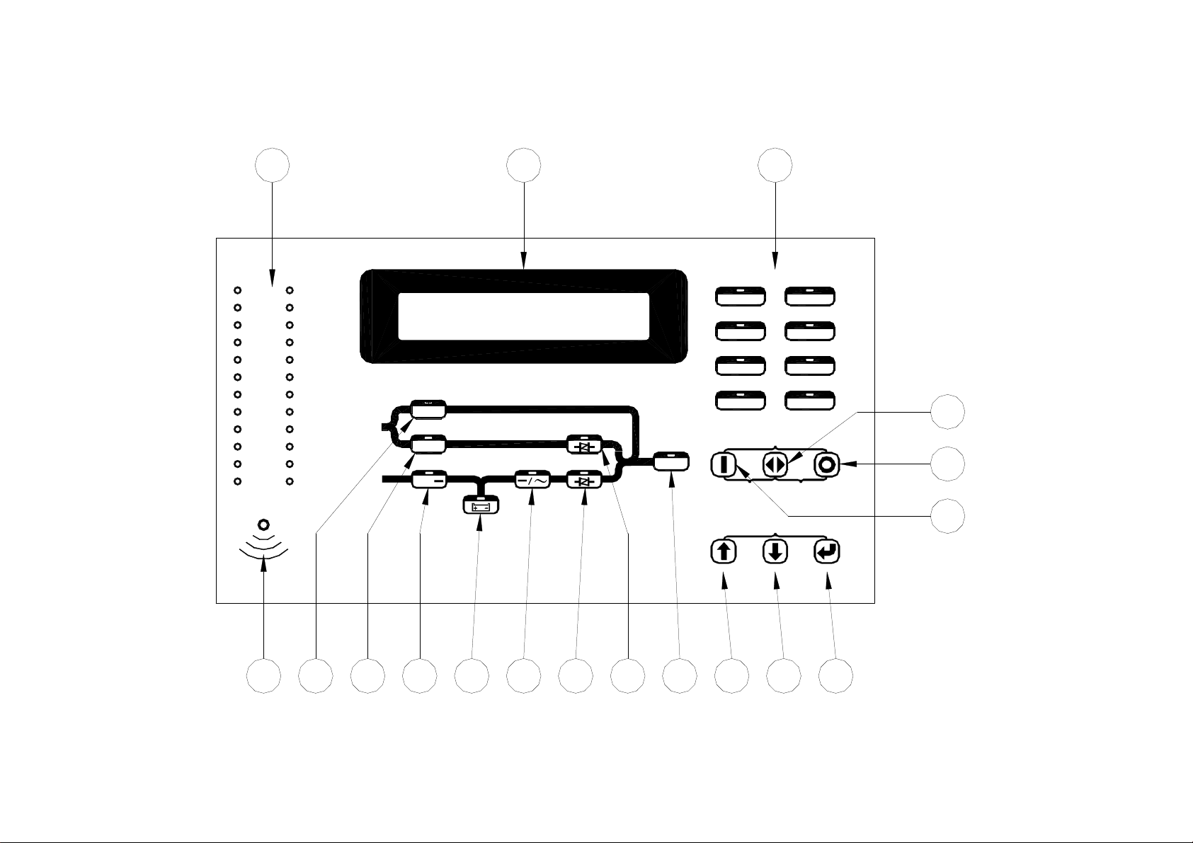
The front panel is located at the front of the PCB holder. It gathers the real time
information of the UPS
for controlling and setting the UPS. So, through this
and shows
them clearly to the user. It also provides switches
panel,
the UPS can be not only a
stand alone machine supplying the load but closely related to the user. Each part of
the panel is explained below.
A: LCD display: Real time status, data or historical events is displayed on the LCD.
The UPS parameters, real time clock, inverter, buzzer also can be set through this
LCD. The LCD is
light
ed
by LEDs for purpose of a sharp display, but in
back
order to lengthen the LED’s life time, the LED will be automatically shut off 3
minute a
fter
no key is activated, will light
up
again when one of the
up/down/enter key is pushed.
B: Status LEDs: 24 LEDs representing all the important information of the UPS
provide most update information to the user. Therefore these LEDs are especially
important when abnormal conditions happen. The 24 information are as below:
INVERTER ON – inverter is running.
INVERTER SS – inverter static switch conducts while the reserve static
switch is opened.
SHORT CIRCUIT – UPS output is in short circuit state.
FUSE/OVER TEMP SD – inverter shutdown due to either fuse broken or
temperature too high.
INVERTER FAIL SHUTDOWN – inverter shutdown due to inverter output
voltage too low.
BYPASS ON SHUTDOWN – inverter shutdown due bypass breaker is closed
when the inverter is running.
HIGH DC SHUTDOWN – inverter shutdown due to DC bus too high when
the inverter is running.
OVERLOAD SHUTDOWN – inverter shutdown due overload the inverter
for a period over the inverter can endue, will restart after 7 seconds.
70% LOAD – load connected to the output is over 70% of the UPS rating.
110% LOAD – load connected to the output is over 110% of the UPS rating.
125% LOAD – load connected to the output is over 125% of the UPS rating.
150% LOAD – load connected to the output is over 150% of the UPS rating.
Page 25

1-21
RESERVE AC FAIL – reserve AC magnitude is out of range.
RESERVE FREQ FAIL – reserve frequency is out of range.
BATTERY LOW – DC bus (or battery) is lower than 320VDC, low battery
shutdown is approaching.
BATTERY LOW SHUTDOWN – inverter shutdown due to DC bus (or
battery) is lower than 295VDC (lower than the acceptable DC voltage of
the inverter.
RECT AC FAIL – rectifier AC magnitude is out of range.
ROTATION ERROR – rectifier AC phase rotation is incorrect.
RECTIFIER SHUTDOWN – rectifier shutdown due to DC bus too high
(over 445VDC), will automatically restart 30 seconds after abnormal
situation has been cleared.
HIGH DC – DC voltage over 430VDC and the bus voltage will be limited at
this voltage.
BOOST CHARGE – the battery is being boost charged by the rectifier.
BATTERY TEST – battery is being tested.
EMERGENT STOP –inverter shutdown due to emergent stop switch is
pushed.
DATA LINE – blinks when data is transmitted to or received from the
communication port.
C: Warning LEDs: When abnormal condition happens, these LEDs will lit to warn
the user according to the cause of the faulty condition. Therefore all these LEDs
should be extinguished under normal condition. These LEDs are as below:
RECT AC FAIL – rectifier AC input is abnormal either due to AC magnitude
out of the range or phase rotation error, rectifier shutdown.
RESERVE FAIL – reserve AC input is abnormal either due to AC magnitude
out of range or frequency out of range.
FUSE/TEMP
– either inverter fuse is blown or over temperature.
OVERLOAD – output is overloaded by over 110%, 125% or 150%.
HIGH DC – the LED will lit as long as the DC voltage is over 430VDC.
Page 26

1-22
BAT LOW – the LED will lit as long as the DC voltage is lower than
320VDC.
BAT LOW STOP – the LED will lit as long as the DC voltage is lower than
295VDC, inverter on is prohibited.
FAULT – the inverter is shutdown due to abnormal conditions such as
overload, short circuit, high DC, fuse over temperature, bypass breaker on
or emergent stop.
Since these LEDs are located behind the transparent window, the user can see
them clearly
without opening
the door.
D: Buzzer outlet: The buzzer is located inside the PCB holder; therefore, a hole is
opened to let the beep
sound
can be heard outside. Usually, the user should not be
expected to watch the UPS all the time, therefore when abnormal conditions
happen audible sound should be emitted to warn the user come over to check
what happens to the UPS. The buzzer will beep under either one of the following
conditions:
INVERTER IS OVERLOADED-
>110%, beep once / 3 seconds
>125%, beep once / second
>150%, beep twice / second
BACK- UP
>320VDC, beep once / 3 seconds
<320VDC, beep twice / second
<295VDC, no beeping
INVERTER IS SHORT CIRCUITED - beep continuously
FUSE BROKEN - beep continuously
HEAT SINK OVER TEMPERATURE - beep continuously
HIGH DC SHUTDOWN - beep continuously
BYPASS ON STOP - beep continuously
Page 27

1-23
EMERGENT STOP - beep continuously
The buzzer will also beep once every time the inverter is switched on or off to
acknowledge the user his key is valid and accepted.
E. Bypass LED: This LED will lit when the maintenance bypass breaker is closed.
When the maintenance bypass breaker is closed, the inverter cannot be switched
on and will stop immediately even when inverter is already running.
F. Reserve LED: This LED will lit when the reserve breaker is closed, and there is
AC power supply present at the reserve terminal.
G. Rectifier LED: This LED will lit when the rectifier is operating normally, it
means the rectifier Mains is within the range specified, the rotation sequence of
three phases are correct, rectifier breaker is closed and no high DC voltage in the
bus.
H. Back-up LED: This LED will lit when the UPS is in back-up mode. This is also
as the indicator for battery test result. If the battery test do not pass, this LED will
flash even the UPS is not in back-up mode to prompt the user to change the
battery.
I. Inverter LED: This LED will lit when the inverter is switched on, therefore this
LED indicates whether the inverter is running or not.
J. Inverter SS LED: This LED will lit when the inverter static switch is turned on
sw
and the reserve static
itch is turned off. That is, the load is supplied from the
inverter. Usually this LED will lit 7sec. after the inverter is switched on.
K. Reserve SS LED: This LED will lit when the reserve static switch is turned on
sw
and the inverter static
itch is turned off. That is, the load is supplied from the
reserve. Since the reserve static switch and inverter static switch will never both
turn on simultaneously, the Inverter SS LED and the Reserve SS LED should
never both lit simultaneously.
L. Output LED: This LED will lit when there is AC power present at the output
terminal. This is an important indication to the user that whether AC is available
at the output or not.
Page 28

1-24
M. Up key: This is a LCD control key. It is for moving the cursor one item upward
when items are
being s
elected or for changing the number/character forward
when data or parameter of the UPS is being set.
N. Down key: This is a LCD control key. It is for moving the cursor one item
downward when items are being selected or for changing the number/ character
backward when data or parameter of the UPS is being set.
O. Enter key: This is a LCD control key. It is for changing backward to the previous
page, and also for
confirming th
e number/character /item is selected.
P. Inverter on switch: It is the inverter control switch. When this key is pushed with
the control key simultaneously, the inverter will be switched on.
Q. Inverter control switch: It is the inverter control switch. When this key is pushed
with the inverter on key simultaneously, the inverter will be switched on.
Similarly, when this key is pushed with the inverter off key simultaneously, the
inverter will be switched off. There this key is a guard for mistaken keys.
R. Inverter on switch: It is the inverter control switch. When this key is pushed with
the control key simultaneously, the inverter will be switched on.
Page 29

2-1
MAXIMUM CHARGE
CURRENT (ADC)
2. TECHNICAL SPECIFICATION
2.1. 20KVA ~ 60KVA UPS 3-Phase Input / 3-Phase Output
TECHNICAL SPECIFICATION
KVA
20
30
40
50
60
RECTIFIER
220V∆ / 380V∆ / 460V∆, 208VY /
INPUT VOLTAGE
380VY / 400VY /
INPUT RANGE 307 –
520V
415VY
INPUT FREQUENCY 50 / 60 Hz +/- 7%
INPUT POWER FACTOR
0.8
NORMAL INPUT CURRENT(A) 36 54 72 90 108
MAXIMUM INPUT CURRENT(A) 45 68 90 113 136
POWER WALK IN 0% - 100% : 20 sec
EFFICIENCY
VOLTAGE REGULATION
99%
1%
CURRENT LIMIT(A) 54 81 108 135 162
RIPPLE VOLTAGE
BATTERY
0.5%
BATTERY TYPE SEAL LEAD ACID / NiCd
NO. OF CELLS 174 /
VOLTAGE RANGE 295 – 410VDC / 285-415VDC
BATTERY LOW VOLTAGE 320VDC / 305VDC
BATTERY LOW STOP VOLTAGE 295VDC / 285VDC
BOOST CHARGE 410VDC / 415VDC
FLOAT CHARGE 396VDC / 410VDC
271
10
15
20
25
30
Page 30

2-2
FREQUENCY LOCK RANGE
45 – 55 Hz / 55 – 65 Hz
THD (LINEAR LOAD)
< 2
%
- <110% CONTINUOUS
- 110 – 125% 15
min
- 125 – 150% 10
min
- > 150% 60 sec
EFFICIENCY (100% LOAD)
93%
93%
93.5%
93.5%
94%
- MAINS -> INVERTER
0
ms
KVA
20
30
40
50
60
INVERTER
DC INPUT RANGE 285 – 415VDC
WAVE FORM
OUTPUT VOLTAGE
208 / 380 / 400 / 415 VY 3 PHASE
SINUSOID
WITH NEUTRAL
OUTPUT POWER FACTOR
VOLTAGE REGULATION 100%
UNBALANCE LOAD
OUTPUT FREQUENCY
(FREE RUNNING)
50 / 60 Hz + / - 0.1 Hz
0.8
+ / - 1
PHASE SHIFT UNDER
100% UNBALANCE LOAD
120 % + / -
OVERLOAD
%
0.5
∘
MAXIMUM OUTPUT
PEAK CURRENT(A)
STATIC SWITCH
87
130
174
218
VOLTAGE RANGE 173 – 277 VAC (LINE TO NEUTRAL)
FREQUENCY RANGE 45 – 55 Hz / 55 – 65 Hz
EFFICIENCY
99.5%
TRANSFER TIME:
- INVERTER -> MAINS 0
ms
- 100% 30 sec
OVERLOAD
- 300% 1 sec
ISOLATION WITH OUTPUT
YES
260
Page 31

2-3
0 – 40℃ ( 32 –
104℉ )
- HEIGHT(mm) 1600
- WIDTH(mm)
550
- LED,LCD,BUZZER
YES
KVA
20
30
40
50
60
OVERALL
CHARACTERISTICS
OVERALL EFFICIENCY 91% 91% 91.5% 92% 92%
OPERATING ENVIRONMENT:
- TEMPERATURE
- HUMIDITY 0% - 90% ( NON–CONDENSING )
-
ALTITUDE <1500 M ABOVE SEA LEVEL
MAXIMUM HEAT
DISSIPATION(KW)
1.3
1.9
2.6
3
WEIGHT(Kg) 250 400 480 550 680
DIMENSION:
- DEPTH(mm)
-
AUDIBLE NOISE < 65 dBA (AT 1 m)
800
STANDARDS:
- EN50091-1,-2
YES
3.5
- FCC CLASS A
YES
PROTECTIONS:
- SHORT CIRCUIT RECTIFIER, RESERVE, BYPASS NFB
- LIGHTNING
MOV
- EMC FILTER INPUT & OUTPUT
- GALVANIC ISOLATION BETWEEN INPUT & OUTPUT
DATA DISPLAY BY LCD
YES
INDICATIONS & ALARMS:
DRY CONTACT
BATTERY START
YES
YES
☆All specifications mentioned above are subject to change without prior notice.
Page 32

2-4
220V∆ / 380V∆ / 460V∆, 208VY /
380VY / 400VY /
415VY
MAXIMUM CHARGE
2.2. 80KVA ~ 160KVA UPS 3-Phase Input / 3-Phase Output
TECHNICAL SPECIFICATION
KVA
80
100 120 160
RECTIFIER
INPUT VOLTAGE
INPUT RANGE 307 –
520V
INPUT FREQUENCY 50 / 60 Hz +/- 7%
INPUT POWER FACTOR
0.8
NORMAL INPUT CURRENT(A) 144 180 216 288
MAXIMUM INPUT CURRENT(A) 180 225 270 360
POWER WALK IN 0% - 100% : 20 sec
EFFICIENCY
VOLTAGE REGULATION
99%
1%
CURRENT LIMIT(A) 216 270 324 432
RIPPLE VOLTAGE
BATTERY
0.5%
BATTERY TYPE SEAL LEAD ACID / NiCd
NO. OF CELLS 174 /
VOLTAGE RANGE 295 – 410VDC / 285-415VDC
CURRENT (ADC)
BATTERY LOW VOLTAGE 320VDC / 305VDC
BATTERY LOW STOP VOLTAGE 295VDC / 285VDC
BOOST CHARGE 410VDC / 415VDC
FLOAT CHARGE 396VDC / 410VDC
40
50
271
60
80
Page 33

2-5
OUTPUT POWER FACTOR
0.8
VOLTAGE RANGE
173 – 277 VAC (LINE TO NEUTRAL)
FREQUENCY RANGE
45 – 55 Hz / 55 – 65 Hz
EFFICIENCY 99.5%
TRANSFER TIME:
- MAINS -> INVERTER
0
ms
- INVERTER -> MAINS
0
ms
- 100%
30 sec
- 300%
1 sec
ISOLATION WITH OUTPUT
YES
KVA
80
100 120 160
INVERTER
DC INPUT RANGE 285 – 415VDC
WAVE FORM
OUTPUT VOLTAGE
208 / 380 / 400 / 415 VY 3 PHASE
SINUSOID
WITH NEUTRAL
VOLTAGE REGULATION
100% UNBALANCE LOAD
+ / - 1
%
FREQUENCY LOCK RANGE 45 – 55 Hz / 55 – 65 Hz
OUTPUT FREQUENCY
(FREE RUNNING)
50 / 60 Hz + / - 0.1 Hz
PHASE SHIFT UNDER
100% UNBALANCE LOAD
120 % + / -
THD (LINEAR LOAD) < 2
- <110% CONTINUOUS
- 110 – 125% 15
%
min
0.5
OVERLOAD
- 125 – 150%
10min
∘
- > 150% 60 sec
EFFICIENCY (100% LOAD) 94.5% 94.5% 95% 95%
MAXIMUM OUTPUT
PEAK CURRENT(A)
STATIC SWITCH
348
432
520
OVERLOAD
693
Page 34

2-6
92.5%
0 - 40℃ ( 32 -
104℉ )
- HEIGHT(mm) 1600
- WIDTH(mm) 1100
- LED,LCD,BUZZER
KVA
80
100 120 160
OVERALL
CHARACTERISTICS
OVERALL EFFICIENCY 92.5%
93% 93%
OPERATING ENVIRONMENT:
- TEMPERATURE
- HUMIDITY 0% - 90% ( NON–CONDENSING )
-
ALTITUDE <1500 M ABOVE SEA LEVEL
MAXIMUM HEAT
DISSIPATION(KW)
4.6
5.4
6.5
WEIGHT(Kg) 820 950 1180 1450
DIMENSION:
- DEPTH(mm)
-
AUDIBLE NOISE < 65 dBA (AT 1 m)
800
STANDARDS:
- EN50091-1,-2
YES
8.7
- FCC CLASS A
YES
PROTECTIONS:
- SHORT CIRCUIT RECTIFIER, RESERVE, BYPASS NFB
- LIGHTNING
MOV
- EMC FILTER INPUT & OUTPUT
- GALVANIC ISOLATION BETWEEN INPUT & OUTPUT
DATA DISPLAY BY LCD
YES
INDICATIONS & ALARMS:
DRY CONTACT
BATTERY START
YES
YES
YES
☆All specifications mentioned above are subject to change without prior notice.
Page 35

2-7
220V∆ / 380V∆ / 460V∆, 208VY /
380VY / 400VY /
415VY
MAXIMUM CHARGE
2.3. 20KVA ~ 50KVA UPS 3–Phase Input / 1-Phase Output
30
TECHNICAL SPECIFICATION
KVA
20
40
50
RECTIFIER
INPUT VOLTAGE
INPUT RANGE 307 –
520V
INPUT FREQUENCY 50 / 60 Hz +/- 7%
INPUT POWER FACTOR
0.8
NORMAL INPUT CURRENT(A) 36 54 72 90
MAXIMUM INPUT CURRENT(A) 45 68 90 113
POWER WALK IN 0% - 100% : 20 sec
EFFICIENCY
VOLTAGE REGULATION
99%
1%
CURRENT LIMIT(A) 54 81 108 135
RIPPLE VOLTAGE
BATTERY
0.5%
BATTERY TYPE SEAL LEAD ACID / NiCd
NO. OF CELLS 174 /
271
VOLTAGE RANGE 295 – 410VDC / 285-415VDC
10
15
20
CURRENT (ADC)
BATTERY LOW VOLTAGE 320VDC / 305VDC
BATTERY LOW STOP VOLTAGE 295VDC / 285VDC
BOOST CHARGE 410VDC / 415VDC
FLOAT CHARGE 396VDC / 410VDC
25
Page 36

2-8
FREQUENCY LOCK RANGE
45 – 55 Hz / 55 – 65 Hz
THD (LINEAR LOAD)
< 2
%
EFFICIENCY (100% LOAD)
93%
93%
93.5%
93.5
173 – 277 VAC (LINE TO
- MAINS -> INVERTER
0
ms
KVA
20
30
40
50
INVERTER
DC INPUT RANGE 285 – 415VDC
WAVE FORM
SINUSOID
OUTPUT VOLTAGE 220 / 230 / 240 V, 1p2w or 1p3w
OUTPUT POWER FACTOR
0.8
VOLTAGE REGULATION
0-100% LOAD
OUTPUT FREQUENCY
(FREE RUNNING)
+ / - 1
50 / 60 Hz + / - 0.1 Hz
%
PHASE DIFFERENCE WITH
+ / -
0.5
∘
RESERVE INPUT
- <110% CONTINUOUS
- 110 – 125% 15
min
OVERLOAD
- 125 – 150% 10
min
- > 150% 60 sec
MAXIMUM OUTPUT
PEAK CURRENT(A)
STATIC SWITCH
260
390
520
VOLTAGE RANGE
FREQUENCY RANGE 45 – 55 Hz / 55 – 65 Hz
EFFICIENCY
99.5%
TRANSFER TIME:
- INVERTER -> MAINS 0
ms
- 100% 30 sec
OVERLOAD
- 300% 1 sec
ISOLATION WITH OUTPUT
YES
650
Page 37

2-9
0 - 40℃ ( 32 -
104℉ )
WEIGHT(Kg)
300
400
480
550
- DEPTH(mm)
800
- LED,LCD,BUZZER
KVA
20
30
40
50
OVERALL
CHARACTERISTICS
OVERALL EFFICIENCY 91% 91% 91.5% 92%
OPERATING ENVIRONMENT:
- TEMPERATURE
- HUMIDITY 0% - 90% ( NON–CONDENSING )
-
ALTITUDE <1500 M ABOVE SEA LEVEL
MAXIMUM HEAT
DISSIPATION(KW)
1.3
1.9
2.6
DIMENSION:
- HEIGHT(mm)
- WIDTH(mm)
-
AUDIBLE NOISE < 65 dBA (AT 1 m)
1600
550
STANDARDS:
- EN50091-1,-2
YES
3
- FCC CLASS A
YES
PROTECTIONS:
- SHORT CIRCUIT RECTIFIER, RESERVE, BYPASS NFB
- LIGHTNING
MOV
- EMC FILTER INPUT & OUTPUT
- GALVANIC ISOLATION BETWEEN INPUT & OUTPUT
DATA DISPLAY BY LCD
YES
INDICATIONS & ALARMS:
DRY CONTACT
BATTERY START
YES
YES
YES
☆All specifications mentioned above are subject to change without prior notice.
Page 38

2-10
220V∆ / 380V∆ / 460V∆, 208VY / 380VY
/ 400VY / 415VY
MAXIMUM CHARGE
CURRENT (ADC)
2.4. 200KVA ~ 320KVA UPS 3-Phase Input / 3-Phase Output
TECHNICAL SPECIFICATION
KVA
200 240 300 320
RECTIFIER
INPUT VOLTAGE
INPUT RANGE 307 – 520V
INPUT FREQUENCY 50 / 60 Hz +/- 7%
INPUT POWER FACTOR 0.8
NORMAL INPUT CURRENT(A) 350 420 525 560
MAXIMUM INPUT CURRENT(A) 437 525 656 700
POWER WALK IN 15% - 100% : 15 sec
EFFICIENCY 99%
VOLTAGE REGULATION 1%
CURRENT LIMIT(A) 525 630 788 840
RIPPLE VOLTAGE 0.5%
BATTERY
BATTERY TYPE SEAL LEAD ACID / NiCd
NO. OF CELLS 174 / 271
VOLTAGE RANGE 295 – 410VDC / 285-415VDC
100
120
BATTERY LOW VOLTAGE 320VDC / 305VDC
BATTERY LOW STOP VOLTAGE 295VDC / 285VDC
BOOST CHARGE 410VDC / 415VDC
FLOAT CHARGE 396VDC / 410VDC
150
160
Page 39

2-11
380 / 400 / 415 V 3 PHASE WITH
NEUTRAL
VOLTAGE REGULATION
0-100% LOAD
OUTPUT FREQUENCY
(FREE RUNNING)
PHASE DIFFERENCE WITH
RESERVE INPUT
MAXIMUM OUTPUT
PEAK CURRENT(A)
- MAINS -> INVERTER
0
ms
KVA
200 240 300 320
INVERTER
DC INPUT RANGE 285 – 415VDC
WAVE FORM SINUSOID
OUTPUT VOLTAGE
OUTPUT POWER FACTOR 0.8
+ / - 1 %
FREQUENCY LOCK RANGE 45 – 55 Hz / 55 – 65 Hz
50 / 60 Hz + / - 0.1 Hz
120°+ / -
0.5
°
THD (LINEAR LOAD) < 5 %
OVERLOAD
- <110% CONTINUOUS
- 110 – 125% 15
- 125 – 150% 10
min
min
- > 150% 60 sec
EFFICIENCY(100% LOAD) 95% 95% 95% 95%
STATIC SWITCH
800
1000
1250
VOLTAGE RANGE 173 – 277 VAC (LINE TO NEUTRAL)
FREQUENCY RANGE 45 – 55 Hz / 55 – 65 Hz
EFFICIENCY 99.5%
TRANSFER TIME:
- INVERTER -> MAINS 0
ms
- 100% 30 sec
OVERLOAD
-
300%
ISOLATION WITH OUTPUT
1 sec
YES
1300
Page 40

2-12
MAXIMUM HEAT
DISSIPATION(KW)
- LED,LCD,BUZZER
KVA
200 240 300 320
OVERALL
CHARACTERISTICS
OVERALL EFFICIENCY 93% 93% 93% 93%
OPERATING ENVIRONMENT:
- TEMPERATURE
0 - 40℃ ( 32 - 104℉ )
- HUMIDITY 0% - 90% ( NON–CONDENSING )
-
ALTITUDE <1500 M ABOVE SEA LEVEL
11.5
13
16.3
WEIGHT(Kg) 2500 2700 3000 3100
DIMENSION:
- HEIGHT(mm) 1600
- WIDTH(mm) 2200
- DEPTH(mm) 800
-
AUDIBLE NOISE < 67 dBA (AT 1 m)
17.4
STANDARDS:
-EN50091-1,2
YES
-FCC CLASS A YES
PROTECTIONS:
- SHORT CIRCUIT RECTIFIER, RESERVE, BYPASS NFB
- LIGHTNING
MOV
- EMC FILTER INPUT & OUTPUT
- GALVANIC ISOLATION BETWEEN INPUT & OUTPUT
DATA DISPLAY BY LCD
YES
INDICATIONS & ALARMS:
DRY CONTACT
BATTERY START
YES
YES
YES
☆All specifications mentioned above are subject to change without prior notice.
Page 41

3-1
3. INSTALLATION
3.1. Site & Environment Consideration
The main function of the UPS is to provide an safe, clean independent electrical
supply to the load so that it is free from any random variations, disturbances or
interruptions of the utility Mains, provide a constant power supply which is
perfectly regulated in both voltage and frequency. And when the Mains is not
available, the UPS can provide optimal back-up time depends on the battery bank
capacity connected to it.
Usually the life expectancy of the UPS is 5 to 10 years (battery is not included,
because life expectancy of battery depend on the type of battery, the temperature
and humidity of the environment it is installed and the type of charger is applied to
the battery). Therefore optimal life expectancy of the UPS can be achieved by
careful consideration of the site and environment.
The following precautions and recommendations should be checked in considering
the site and environment of the UPS:
(a) The UPS should be located on place with adequate ventilation (refer to the
specification of the heat dissipation of the UPS). If the UPS is installed indoors,
care must be taken in insuring the evacuation of heat from the closed room.
(b) Adequate space (at least 1M) should be allowed to open the door without
obscured by other objects for operation or maintenance. Adequate space (at least
1M) should be allowed at the top of the UPS, because heat dissipation is
ventilated through the top openings (ventilation booth is available upon request).
(c) Do not put any objects on the top of the UPS to obscure the ventilation. Do
not locate the UPS near to any heat source, or machinery, which produce
metallic coil dust or powder, or facility that will produce corrosive substances or
vapor.
(d) Do not locate the UPS below the shower of fire extinguishing system
(abnormal conditions of the UPS should be protected by cutoff the power
supply).
Page 42

3-2
(e) It is necessary to guarantee the temperature and humidity values of the site
into which the UPS will be installed should be within the range allowed by the
specification. The UPS is capable of
continuous norm
al operation within a
temperature range of 0℃(32℉) to 40℃(104℉). For optimal performance and
reliability to prolong UPS’s lifetime, it is recommended to keep the environment
temperature below 25℃, and humidity below 80%.
(f) If the UPS is installed outdoor, avoid direct exposure of the UPS to the
sunlight and rain. Avoid direct confrontation with sand, dust or wind.
(g) The floor loading capacity should be big enough to endure the weight of the
UPS. Four tough right angled steel foot stands are attached with the UPS, please
insert the corresponding screw nut (dia.1/2”) into the floor for securing the UPS
on the floor when it is locate on territory where earthquake is expected or
moving vehicle, or tanker etc. Dimensions of the 1/2” nut on the to secure the
UPS are shown below.
Page 43

3-3
(h) Walls, ceilings, floors or anything near to the UPS should be preferably
constructed
of non-combustibl
e materials. The portable fire extinguisher should
be accessible nearby in case of hazard.
(i) Avoid accumulating litter or trash of any sort in or around the UPS system.
The floor area surrounding the UPS should be kept clean so that metallic powder
and filings are not
sucked into
the unit thus causing a short circuit and damage
to the system.
(j) Access to the UPS room should be limited to a minimum number of operation
and maintenance personnel only. The doors should be kept locked and the keys
should be confined to authorized personnel only.
(k) Personnel who operate or maintain the UPS system should be proficient in
normal and emergency operational procedures. New personnel should be
trained and qualified prior to operate the equipment.
(l) Although the UPS has past the international EMC tests, it is not
recommended to install the UPS near to any equipment that is susceptible to
electro-magnetic interference, such as computer system, monitors, radio etc.
(m) It preferably to place the UPS near to the source than near to the load.
Page 44

3-4
3.2. Unpacking
Carefully take off all the packaging material of the UPS, then carefully locate the
UPS onto site which has selected with all the points in section 3.1 kept in mind.
The UPS had past the production testing and QC checking all the electrical and
mechanical characteristics in detail prior to shipment from the factory, therefore the
UPS should be in proper conditions upon receipt. Once receive the UPS, first check
visually the outlook and mechanical structure if any physical damage was made
during transportation.
Then check if all the accessories/options (match with your purchase order) have
been attached.
- DOOR KEY
- THIS INSTRUCTION MANUAL
- BATTERY FUSE (FOR BATTERY CABINET ONLY)
- SPARE SCREWS FOR COVER PLATE
- SPARE SCREWS FOR CONNECTION TERMINALS etc.
Lastly, check if the specification of the UPS identical to the specification you order.
The key items in the specification you must check are:
- RATED POWER OF THE UPS,
- INPUT VOLTAGE & FREQUENCY
- OUTPUT VOLTAGE & FREQUENCY
- NO. OF OUTPUT PHASES (1Φ OR 3Φ)
- BATTERY VOLTAGE OR CELL NO.
Check also the necessary documentation that is attached:
- GUARANTEE CARD
-
AGENT/SERVICE CENTER INFORMATION
Page 45

3-5
230/400V 3Φ
230/400V 3Φ
230/400V 3Φ
230/400V 3Φ
3.3. Cable Selection
The following tables list all the information between KVA of the UPS and the size
and rating of the cables. Inadequate cable size or over sized breaker will incur risk
of fire or damage of insulation. Therefore, please look up the following tables to
determine the input circuit breaker rating and the size of cable for input, output and
battery connections. These data are for reference; final decision should be made in
accordance with the local electrical regulations.
BREAKER RATING FOR INPUT
KVA INPUT Imax(A) NFB(A)
20
230/400V 3Φ
30
230/400V 3Φ
40
230/400V 3Φ
50
230/400V 3Φ
60
230/400V 3Φ
80
230/400V 3Φ
100 230/400V 3Φ
120
160
240
320
CABLE SIZE FOR INPUT
50
73
98
122
147
172
215
258
344
520
692
50
75
100
125
150
175
225
300
350
500
700
KVA INPUT In(A) R/S/T(mm2) N(mm2)
20
230/400V 3Φ
30
230/400V 3Φ
40
230/400V 3Φ
50
230/400V 3Φ
60
230/400V 3Φ
36
54
72
90
108
8
14
22
30
38
14
22
30
38
50
Page 46

3-6
230/400V 3Φ
230/400V 3Φ
230/400V 3Φ
230/400V 3Φ
230/400V 3Φ
230/400V 3Φ
230/400V 3Φ
230/400V 3Φ
230/400V 3Φ
230/400V 3Φ
230/400V 3Φ
80
230/400V 3Φ
144
50
80
100 230/400V 3Φ
120 230/400V 3Φ
160 230/400V 3Φ
240 230/400V 3Φ
320 230/400V 3Φ
CABLE SIZE FOR OUTPUT
KVA OUTPUT In(A) R/S/T(mm2) N(mm2)
20
30
40
50
60
180
216
288
416
100*2 125*2
554
150*2 200*2
29
46
58
72
91
80
100
60*2
8
14
22
30
38
100
125
80*2
14
22
30
38
60
80
100
120
160
240
320
20
230V 1Φ
30
230V 1Φ
40
230V 1Φ
50
230V 1Φ
116
144
182
232
348
100*2 125*2
463
125*2 150*2
91
130
182
217
60
80
100
60*2
38
60
100
150
80
100
125
80*2
60
80
125
60*2
Page 47

3-7
30 90 100 38
80 240
125*2
38*2
100 300
160*2
50*2
320 960
200*4
80*4
FUSE RATING & CABLE SIZE FOR BATTERY
☆ THE BATTERY VOLTAGE IS 295 – 410V
KVA Imax(A) FUSE(A)
20
40
50
60
60
120
150
180
63
125
160
200
CABLE(mm2)
22
38
50
80
120
160
240
360
200*2
480
200*2
720
200*4
80*2
80*2
80*4
Page 48
3-8
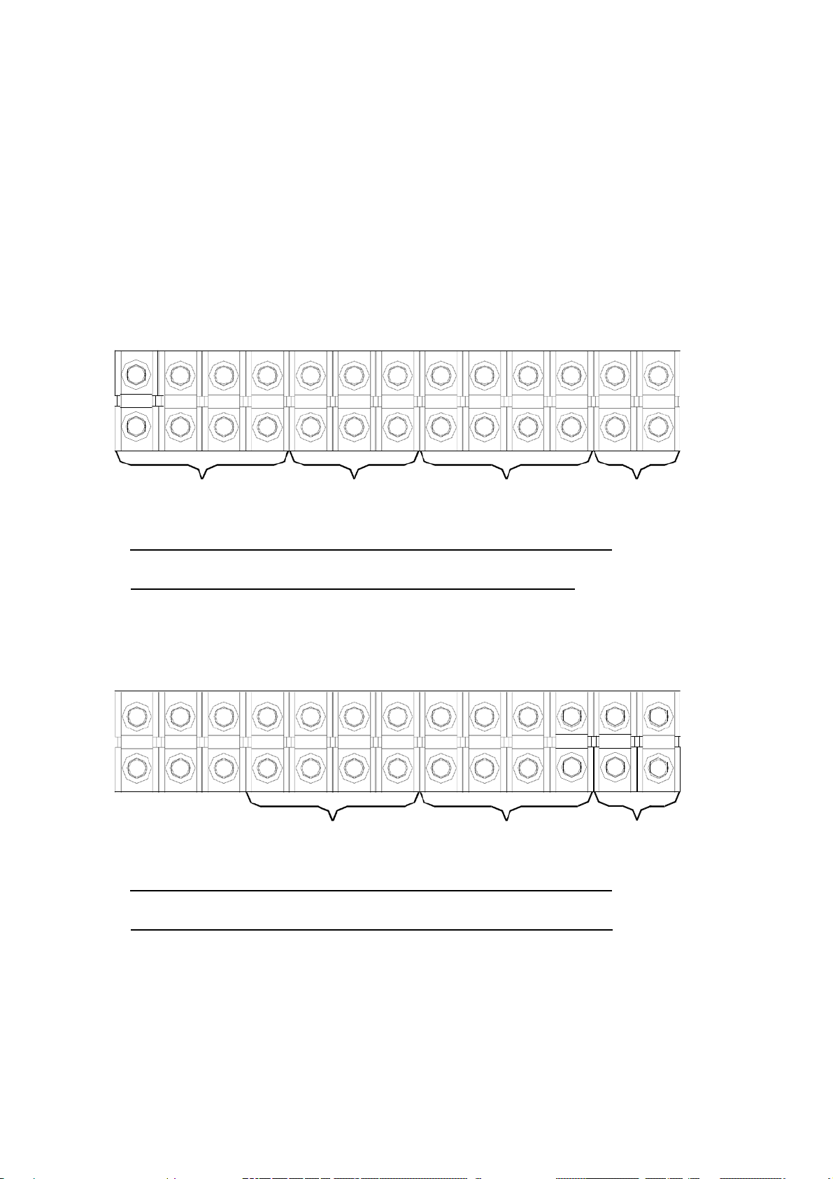
3.4. Terminal Connection
Although different KVA of the UPS may have different cable connection terminal,
all our standard UPS connection terminal alignment falls into one of the following
types:
RR RS RT IN IR IS IT OR OS OT ON B+ B-
RESERVE
INPUT
INPUT OUTPUT INPUT
RECTIFIER
UPS
BATTERY
3 PHASE INPUT / 3 PHASE OUTPUT
TERMINAL WITH TWO SOURCE
IN IR IS
RECTIFIER & RESERVE
INPUT
IT OR OS OT ON B+ B-
UPS
OUTPUT
BATTERY
INPUT
3 PHASE INPUT / 3 PHASE OUTPUT
TERMINAL WITH SINGLE SOURCE
☆☆☆ Three extra terminals are installed for convenience of changing the unit to
separate reserve input.
Page 49

3-9
RT
IN
IR
IS
IT
OR
ON
B+
B-
RT
IN
IR
IS
IT
OR
ON
B+
B-
For single phase output UPS, the current is very much larger in single phase
terminal, therefore the terminal looks bigger than it is needed.
RESERVE
INPUT
RECTIFIER
INPUT
UPS
OUTPUT
3 PHASE INPUT / 1 PHASE OUTPUT
TERMINAL WITH TWO SOURCE
BATTERY
INPUT
RECTIFIER & RESERVE
INPUT
UPS
OUTPUT
BATTERY
INPUT
3 PHASE INPUT / 1 PHASE OUTPUT
TERMINAL WITH SINGLE SOURCE
☆☆☆ Extra empty terminals are installed for convenience of changing the unit to
separate reserve input.
Page 50

4-1
4. OPERATIONS
After all cables have been connected, the UPS is ready to operate once power
source is available at the
input
terminal. Before turn on any switch or breaker,
check once again the following points listed below:
(a) Check the input voltage if it conforms with the UPS’s rated input
voltage.
(b) Check the input frequency if it conforms with the UPS’s rated input
frequency.
(c) Check if all load at the output is switched off.
(d) All breakers and the battery dis-connector are opened.
(e) If there is anything not belongs to the UPS exits inside the UPS.
4.1. Switch on Procedure
If you want to start the UPS from completely shutoff to normal operation, you can
follow the steps below to turn on the UPS. (But this procedure is for standard
system, 380/220V 3 phases 4 wires Input, 10~160KVA. For special specification
and those above 160KVA, please refer to the brief instruction label stuck in front
of the PCB holder.)
(a) Close the reserve breaker – The reserve and output LED on the mimic will
lit up, indicating the reserve static switch loop is energized,
therefore the output has power now. The power supply in the UPS
also established. The fans will rotate too.
(b) Close the rectifier breaker - The rectifier will be automatically started if the
power source connected is correct. The DC voltage will slowly
rise up (15 – 30 sec.) until the designated voltage is reached, and
will keep the value anyhow. Now, the DC is already ready for the
inverter.
(c) Close the battery breaker - A fuse holder is employed the battery to the DC
bus for safety purpose. Now the battery will take over to supply
the DC bus if rectifier mains fail.
Page 51

4-2
~
~
~
~
/
~
(d) Push inverter on switch – To on the inverter, the inverter on switch and the
(e) Check if the mimic LED is correct, as shown in the figure. All warning
~
MIMIC DISPLAY UNDER NORMAL OPERATION
control switch must be pressed simultaneously. The inverter will
start working and inverter output will be established in 4 sec. The
load will be automatically transferred to the inverter 3 sec. later.
Now the UPS is in normal operation now.
/
~
LEDs on the right hand
and ‘INVERTER SS’ on the left hand side should lit.
over 70%, the ‘70% LOAD’ LED will also lit.
4.2. Shutdown Procedure
If you want to shutdown the UPS completely (no power at output or inside),
please follow the
380/220V 3 phases 4 wires Input, 10~160KVA. For special specification and those
above 160KVA, please refer to the brief instruction label stuck in front of the PCB
holder.)
(a) Switch off the inverter – The inverter can be switched off by pressing the
steps
below.
inverter off switch and the control switch simultaneously. And the
load will be automatically transferred to reserve without
interruption.
(But this procedure is for standard system,
side
is off, two LEDs: ‘INVERTER ON’
If
the load is
Page 52

4-3
(b) Open the battery breaker – If you want to shutdown all the power of the
UPS, continue to open the battery breaker. Now the DC bus is
(c) Open the rectifier breaker – Open the rectifier breaker will then further
take the power source away from the DC bus; therefore the DC
bus will start to drop slowly. After 5 min., the DC bus will drop to
a safe level (let say 20VDC).
only supported by the rectifier.
(d) Open the reserve breaker – Before opening the reserve breaker, there is
power exists at the output, but after opening the reserve breaker,
the output (or load) will no longer have power supply now.
Therefore, before opening the reserve breaker must make sure
there is no critical load connected to the output.
(e) At last all power has been cut off now, there should none of the LED or
LCD lit. The UPS now is completely shut off.
4.3. From Inverter to Bypass Procedure
If you want to stop the UPS for maintenance and do not stop the power supply
from the load, you can follow the steps below to turn the UPS to maintenance
bypass mode without interrupting the output power
supply. (But
this procedure is
for standard system, 380/220V 3 phases 4 wires Input, 10~160KVA. For special
specification and those above 160KVA, please refer to the brief instruction label
stuck in front of the PCB holder.)
(a) Switch off the inverter – The inverter can be switched of by pressing the
inverter off switch and the control switch simultaneously. And the
load will be automatically transferred to reserve without
interruption.
Page 53

4-4
(b) Open the battery breaker – You have to shutdown the power inside the UPS;
therefore, continue to
open
the battery breaker.
(c) Open the rectifier breaker – Open the rectifier breaker will then further
take the power source away from the DC bus; therefore, the DC
bus will start to drop slowly. After 5 min., the DC bus will drop to
a safe level (let say 20VDC).
(d) Close the bypass breaker – Now the reserve breaker and reserve static
switch is still conducting, therefore when maintenance bypass
breaker is closed, power will flow through the bypass loop instead
of the reserve loop because the impedance of bypass loop is lower.
(e) Open the reserve breaker – You can now open the reserve breaker to free
the UPS from any
power supply.
4.4. From Bypass to Inverter Procedure
If the UPS is in maintenance bypass mode, and you want to turn the UPS to
normal mode without interrupting the output AC, please follow the steps below.
(But this procedure is for standard
system, 380/220V
3 phases 4 wires Input,
10~160KVA. For special specification and those above 160KVA, please refer to
the brief instruction label stuck in front of the PCB holder.)
(a) Close the reserve breaker – The reserve and output LED on the mimic will
lit up, indicating the reserve static switch loop is energized,
therefore the output has power now. The power supply in the UPS
also established. The fans will rotate too.
(b) Open the bypass breaker – The inverter cannot be switched on with the
maintenance bypass
breaker
is closed (because the CPU will
sense the breaker and prevent the inverter to connect directly to
AC source). And the reserve breaker has already closed, therefore
power goes through the reserve loop if bypass breaker is open, AC
at output will not be interrupted.
Page 54

4-5
(c) Close the rectifier breaker - The rectifier will be automatically started if the
power source connected is correct. The DC voltage will slowly
rise up (15 – 30sec.) until the designated voltage is reached, and
will keep the value anyhow. Now, the DC is already ready for the
(d) Close the battery breaker - A fuse holder is employed in the battery to the
inverter.
DC bus for
safety purpose.
Now the batteries will take-over to
supply the DC bus if rectifier mains fail.
(e) Push inverter on switch – To on the inverter, the inverter on switch and the
control switch must be pressed simultaneously. The inverter will
start working and inverter output will be established in 4 sec. The
load will be automatically transferred to the inverter 3 sec. later.
Now the UPS comes again into normal operation now.
Page 55

5-1
5. LCD DISPLAY
The LCD can display information much more than LED can do. In order to make
the display sharp
and readab
le, the LCD is back-lighted by LEDs. But since we
want to further prolong the life time of the LED, the CPU will cut off the power
of the LED 3 minutes after the last key of either UP, DOWN or ENTER is pressed.
Of course the back light will continue if the UP, DOWN or ENTER key is
consecutively being pressed. We start from the first page of the LCD. This screen
will pop out once the system power is enabled (i.e. the default screen).
5.1. Menu 0 – Main Menu
W E L C O M E T O U S E T H E U P S
M O D E L : 5 0 3 3 A S / N : 1 2 3 4 5 6 7 8 9 0 I D : 0 1
5 0 K V A I : 2 2 0 / 3 8 0 V / 5 0 H Z O : 2 2 0 / 3 8 0 V / 5 0 H Z
2 0 0 2 / 0 2 / 0 1 T U E 0 8 : 0 0 A M
The first row will display the greeting context being set by the factory or sole
agent. Changing the
context of
this row is not recommended. The model no.
(MODEL), serial no.(S/N), and the identification no.(ID) are displayed in the
second row. While the third row will display the KVA rating, input rating and
output rating of the UPS. Changing the model no. of the second row will change
the rating displayed in the second row too (rating is automatically generated by
CPU inside the UPS according to the MODEL no.).
WARNING: Never change the model number yourself, because some
parameters will be changed along with the model number.
Page 56

5-2
Serial number is set by factory for the convenience of maintenance personnel who
may need to take
down
the serial no. of the UPS he has attended. The
identification no. is set only when external module connect to more than one UPS,
each UPS must have a unique number to identify itself, and it should be set by
installation technical personnel after installation. The YEAR/MONTH/DATE,
DAY OF THE WEEK, HOUR: MINUTE and AM (PM) from the real time clock
inside the UPS are displayed in the fourth row for user’s reference and stamping
the date and time in the historical data when abnormal conditions happen. By
pressing one of the UP, DOWN or ENTER key, the LCD will change to another
screen, the MENU 1.
5.2. Menu 1 – Select Menu
< S E L E C T M E N U >
→ S T A T U S / W A R N / F A U L T P A R A M E T E R S E T
R E A L T I M E D A T A
H I S T O R I C A L D A T A E X I T
It is a select menu with cursor (→) for user to select what type of data the user
what to view or may the user would like to change the settings of the UPS, such
as inverter on/off, buzzer on/off, charging time and magnitude, date/time etc. The
cursor
( → ) can be moved upward by the
downward by the
DOWN(
↓ ) key. The selection is confirmed by pressing the
UP( ↑ ) key, and can be moved
ENTER (←┘), and change to the menu which the cursor is pointing at. If the
item ‘PARAMETER SET’ is selected, the LCD will jump into a screen which will
ask the user to key in the password. See the figure below.
P A S S W O R D : 1 2 3 4
Page 57

5-3
The number can be changed upward or downward by the UP( ↑ ) or the
DOWN(↓) key, and can be confirmed by the ENTER(←┘) key. The password is
a 4 digit number. The selection will continue if correct password is entered, or
will go back to MENU 0 the MAIN MENU if
no
correct password is entered after
3 trials. The password for entering the < PARAMETER SET > menu is 1-2-3-4.
The entering of MENU 12 – the OTHER SETTING menu is permitted by another
password, only released to the maintenance personnel. User can ask the sole agent
if he really need it.
If ‘EXIT’ is selected (blinking instead of pointed by cursor), the screen will go
back to the MENU 0.
5.3. Menu 2 – Status / Warning Menu
< S T A T U S > < W A R N I N G >
R E C T I F I E R = O N
I N V E R T E R = O F F
L O A D O N I N V E R T E R
It is a display menu jump from MENU 1 when STATUS/WARN/FAULT is
selected. The left hand side of this menu shows the real time status of the rectifier,
inverter and static switch states. While the right hand side shows the warning or
fault condition if any. Therefore, under normal condition, the LCD display should
be exactly the same as the figure shown above. When minor abnormal condition
happens it will be shown under the title < WARNING >, but will be overridden by
fault message if more serious abnormal condition happens, and the title <
WARNING > will change to < FAULT >. For example, short circuit happens at
the output, this screen will display as follows:
< S T A T U S > < F A U L T >
R E C T I F I E R = O N S H O R T C I R C U I T !
I N V E R T E R = O F F
L O A D O N I N V E R T E R
Page 58

5-4
The inverter should be shut off under short circuit. Since the CPU detect it is
short circuit, in order to avoid unnecessary tripping and hurting of the breaker, the
static switch remains in conducting the inverter (will not transfer to reserve).
List below are all the warning conditions that can be displayed (they are arranged
in order of priority, start with the highest priority):
1st row : BYPASS ON / RECT AC FAIL / RECTIFIER PHASE ERROR /
2nd row : 170% OVERLOAD / 150% OVERLOAD / 125% OVERLOAD /
110% OVERLOAD
RESERVE FREQ. ERROR
3rd row : BATTERY LOW STOP / BATTERY LOW / BATTERY BAD /
BATTERY GND FAULT / BATTERY TESTING
Lists below are all the fault conditions that can be displayed:
1st row : HIGH DC SHUTDOWN
2nd row: SHORT CIRCUIT! / FUSE/OVERHEAT / OVERLOAD
SHUTDOWN / EMERGENT STOP / INVERTER ABNORMAL
3rd row : BYPASS ON SHUTDOWN
The UP (↑ ) or DOWN (↓ ) key has no function in this menu. The screen will
go back to MENU 1 – the SELECT menu, when ENTER (←┘) is pressed.
5.4. Menu 3 – Real Time Data Menu
< R E A L T I M E D A T A >
→ R E C T I F I E R D A T A O T H E R D A T A
R E S E R V E D A T A
O U T P U T D A T A E X I T
Page 59

5-5
It is a select menu jump from MENU 1 when the REAL TIME DATA is selected.
The cursor (→) is used to select what type of real time data the user what to view,
such as RECTIFIER DATA, RESERVE DATA, OUTPUT DATA, OTHER DATA
etc. The cursor (→) can be moved upward by the UP (↑) key, and can be moved
downward by the DOWN (↓) key. The selection is confirmed by pressing the
ENTER (←┘), and change to the menu which the cursor is pointing at.
If ‘EXIT’ is selected (blinking instead of pointed by cursor), the screen will go
back to the MENU 1- the SELECT MENU.
5.5. Menu 4 – Historical Event Menu
< D A T E / T I M E / E V E N T S > R U N : 2 1 Y R 0 3 M O
2 0 0 0 \ 0 3 \ 2 9 0 9 : 3 2 S H O R T C I R C U I T !
2 0 0 0 \ 1 2 \ 0 1 2 2 : 1 5 S H O R T C I R C U I T !
2 0 0 1 \ 0 1 \ 1 0 1 5 : 4 7 H I G H D C S H U N T D O W N
It is a display menu jump from MENU 1 when HISTORICAL DATA is selected.
The records stored in EEPROM when abnormal events happened are displayed in
this menu. The record display is started with the date and time stamped when the
abnormal condition happened. Therefore, it is possible for the user or
maintenance personnel to trace back what happen to the UPS in the past. 77
records can be stored in one EEPROM, can be increased to 154 records with 2
EEPROMs. All these records will not be erased by cutting off of the power supply
or complete shutdown of the UPS, i.e. they will be kept in EEPROM forever
except over written by the 78th (or the 155th) records.
3 records can be displayed each time on the screen. The records displayed (once
this menu is popped) are the 3 most update records in the EEPROM. The
displayed records will move one record upward when the UP (↑) key is pressed,
and move one record downward when the DOWN (↓) key is pressed.
Page 60

5-6
The abnormal conditions can be displayed are listed below:
HIGH DC SHUTDOWN / SHORT CIRCUIT! / FUSE/OVERHEAT /
OVERLOAD SHUTDOWN / EMERGENT STOP / INVERTER ABNORMAL
/ BYPASS ON SHUTDOWN
Besides, on the top right corner the screen, the UPS run time is displayed in
year/month for the reference of the user or maintenance personnel to estimate the
time for maintenance.
The screen will go back to MENU 1- SELECT MENU by pressing the ENTER
(←┘) key.
5.6. Menu 5 – Parameter Setting Menu
< P A R A M E T E R S E T T I N G >
→ I N V E R T E R = O N / O F F D A T E / T I M E
B U Z Z E R = O N / O F F
B O O S T C H A R G E E X I T
It is a parameter setting menu jump from the MENU 1 - SELECT MENU when
the item < PARAMETER SET > is selected and correct password has been
entered. The cursor (→) is used to select what type parameter the user want to set,
such as INVERTER ON/OFF, BUZZER ON/OFF, BOOST CHARGE,
DATE/TIME etc. The cursor (→) can be moved upward by the UP (↑) key, and
can be moved downward by the DOWN (↓) key. The selection is confirmed by
pressing the ENTER (←┘) key.
The first item can be set is the INVERTER ON/OFF, when it is selected
‘INVERTER ON/OFF’ will be displayed, where the ‘ON’ will blink if the inverter
status is on, and the ‘OFF’ will blink if the inverter status is off. The intended
(
status can be changed by UP
↑ ) or DOWN ( ↓ ) key, and is confirmed by
ENTER
selected
(
← ┘
or
) key. Then ‘INVERTER = ON’ will be displayed if ‘ON’ is
‘INVERTER = OFF’ will be displayed if ‘OFF’ is selected, the UPS
will switch on or off the inverter according to your selection.
Page 61

5-7
The second item can be set is the BUZZER ON/OFF, when it is selected
‘BUZZER ON/OFF’ will be displayed, where the ‘ON’ will blink if the buzzer
status is on, and the ‘OFF’ will blink if the buzzer status is off. The intended
(
status can be changed by UP
↑ ) or DOWN ( ↓ ) key, and is confirmed by
ENTER (←┘) key. Then ‘BUZZER = ON’ will be displayed if ‘ON’ is selected
or ‘BUZZER = OFF’ will be displayed if ‘OFF’ is selected, the UPS will switch
on or off the buzzer according to your selection.
The third item can be set is the BOOST CHARGE, when it is selected the screen
will jump to MENU 10 the BOOST CHARGE SETTING MENU, and the setting
method will be explained later.
The forth item can be set is the DATE/TIME, when it is selected the screen will
jump to MENU 11 the
DA
TE TIME SETTING MENU, and the setting method
will be explained in that section.
If ‘EXIT’ is selected (blinking instead of pointed by cursor), the screen will go
back to the MENU 1- the SELECT MENU.
5.7. Menu 6 – Rectifier Data Menu
< R E C T I F I E R D A T A >
R - N = X X X V a c S - N = X X X V a c T - N = X X X V a c
R E C T I F I E R F R E Q U E N C Y = X X H Z
This menu comes from MENU 3 – the REAL TIME DATA MENU, when the
<RECTIFIER DATA> is selected. It is a data display menu which shows real time
data
of
the rectifier, such as RECTIFIER
FREQUENCY,
R-N/S-N/T-N
VOLTAGE, etc., for the user’s reference. The phase to phase voltage display is
also available when input is a delta (△) connected source.
The UP (↑) or DOWN (↓) key has no function in this menu. The screen will go
back to MENU 3 – the REAL TIME DATA menu, when ENTER (←┘) is pressed.
Page 62

5-8
5.8. Menu 7 – Output Data Menu
< O U T P U T D A T A >
L O A D : R = X X X % S = X X X % T = X X X %
R - N = X X X V a c S - N = X X X V a c T - N = X X X V a c
O U T P U T F R E Q U E N C Y = X X H Z
This menu comes from MENU 3 – the REAL TIME DATA MENU, when the
<OUTPUT DATA> is selected. It is a data display menu, which shows real time
data of the output and load, such as OUTPUT FREQUENCY, LOAD % OF R/S/T,
OUTPUT R-N/S-N/T-N VOLTAGE, etc., for the user’s reference. The phase to
phase voltage display is also available when input is a delta (△) connected source.
The UP (↑) or DOWN (↓) key has no function in this menu. The screen will go
back to MENU 3 – the REAL TIME DATA menu, when ENTER(←┘) is pressed.
5.9. Menu 8 – Other Data Menu
< O T H E R D A T A >
T E M P E R A T U R E = X X C
D C V O L T A G E = X X X V d c
C H A R G E C U R R E N T = X X X A
This menu comes from MENU 3 – the REAL TIME DATA MENU, when the
<OTHER DATA> is selected. It is a data display menu, which shows real time
data of the UPS, such as TEMPERATURE, DC VOLTAGE, CHARGE OR
DISCHARGE CURRENT etc., for the user’s reference. If the UPS is in normal
operation mode, the data in the last row is the charging current of the battery, the
title is ‘CHARGE CURRENT =’, see the figure shown above. If the UPS is in
row
back-up mode, the data in the last
is the discharging current of the battery,
and the title will be ‘DISCHARGE CURRENT =’ see the figure below.
Page 63

5-9
< O T H E R D A T A >
T E M P E R A T U R E = X X C
D C V O L T A G E = X X X V d c
D I S C H A R G E C U R R E N T = X X X A
The UP (↑) or DOWN (↓) key has no function in this menu. The screen will
go
back to MENU 3 – the REAL TIME DATA menu, when ENTER(←┘) is
pressed.
5.10. Menu 9 – Reserve Data Menu
R E S E R V E F R E Q U E N C Y = X X H Z
R - N = X X X V a c S - N = X X X V a c T - N = X X X V a c
< R E S E R V E D A T A >
This menu comes from MENU 3 – the REAL TIME DATA MENU, when the
<RESERVE DATA> is selected. It is a data display menu, which shows real time
data of the reserve input, such as RESERVE FREQUENCY, R-N/S-N/T-N
VOLTAGE, etc., for the user’s reference. The phase to phase voltage display is
also available when reserve input is a delta (△) connected source.
The UP (↑) or DOWN (↓) key has no function in this menu. The screen will go
back to MENU 3 – the REAL TIME DATA menu, when ENTER (←┘) is pressed.
5.11. Menu 10 – Boost Charge Setting Menu
< B O O S T C H A R G E S E T T I N G >
→ A U T O - B O O S T ( M O N T H ) = 0 4
A U T O - B O O S T ( B A T T L O W ) = 0 8
C H A R G E C U R R E N T = L O E X I T
Page 64

5-10
This menu jumps from MENU 5 the PARAMETER SETTING menu when the
item BOOST CHARGE is selected. The user can change the charger parameters
through this menu. The cursor (→) can be moved upward by the UP (↑) key, and
can be moved downward by the DOWN (↓) key. The selection is confirmed by
pressing the ENTER (←┘) key. See in the above figure.
< B O O S T C H A R G E S E T T I N G >
→ A U T O - B O O S T ( M O N T H ) = 0 4 0 8 1 2 1 6 2 0 2 4
A U T O - B O O S T ( B A T T L O W ) = 0 4
C H A R G E C U R R E N T = L O E X I T
When AUTO-BOOST (MONTH) is selected, all the value that can be selected
will be shown (04/08/12/16/20/24). The battery will be boost charged once every
month. The boost charge time is set by this row; the unit of the values is hour. The
current value (or the value being aimed at) will flash for indication and is
confirmed by the ENTER (←┘) key. Longer time is selected for bigger battery
according to the need of the user. Refer to the above figure.
< B O O S T C H A R G E S E T T I N G >
A U T O - B O O S T ( M O N T H ) = 0 4
→ A U T O - B O O S T ( B A T T L O W ) = 0 4 0 8 1 2 1 6 2 0 2 4
C H A R G E C U R R E N T = L O E X I T
When AUTO-BOOST (BATT LOW) is selected, all the value that can be selected
will be shown (04/08/12/16/20/24). The battery will be boost charged, every time
the battery has been consumed to below 12V/battery or 2V/cell, the boost charge
time is set by this row, the unit of the values is hour. The current value (or the
value being aimed at) will flash for indication and is confirmed by the ENTER
(←┘) key. Longer time is selected for bigger battery according to the need of the
user. See the figure above.
< B O O S T C H A R G E S E T T I N G >
A U T O - B O O S T ( M O N T H ) = 0 4
A U T O - B O O S T ( B A T T L O W ) = 0 4
→ C H A R G E C U R R E N T = L O M E H I E X I T
Page 65

5-11
When CHARGE CURRENT is selected, the values that can be selected will be
shown (LO/ME/HI). When the battery is boost charged by whatever the reason,
the charging current will be limited by a value according the setting in this row.
The current value (or the being aimed at) will flash for indication and is
confirmed by the ENTER (←┘) key.
The value can be selected roughly by a simple rule listed below:
BACK-UP TIME SETTING
10 – 30 MIN LO
30MIN – 1HOUR ME
> 1 HOUR HI
If ‘EXIT’ is selected (blinking instead of pointed by cursor), the screen will go
back to the MENU 5- the PARAMETER SETTING menu.
5.12. Menu 11 – Data Time Setting Menu
< D A T E T I M E S E T T I N G >
→ Y E A R = X X X X
M O N T H = X X M I N U T E = X X
D A Y = X X D A Y O F T H E W E E K = M O N E X I T
H O U R ( 2 4 H ) = X X
This menu jumps from MENU 5 the PARAMETER SETTING menu when the
item DATE/TIME is selected. The user can change the YEAR/MONTH/DAY/,
HOUR/MINUTE/DAY OF THE WEEK of the real time clock through this menu.
Once this menu is popped, the current value in the real time clock will be shown.
The cursor ( →) can be moved upward by the UP(↑) key, and can be moved
downward by the DOWN(↓) key to the item you want to change. The selection is
confirmed by pressing the ENTER (←┘) key. See the figure above. The values to
be entered are numbers except the DAY OF THE WEEK (MON, TUE… are
provided for your selection). The values that can be entered are restricted to
certain values according to which item is being set, the values are listed below:
Page 66

5-12
- YEAR : 1998 – 2097
- MONTH : 01-12
- DAY : 01 – 31 (internal calendar will correct it if 31 is entered to a 30day
- HOUR : 0 – 23
month)
- MINUTE : 0 - 59
- DAY OF THE WEEK : MON, TUE, WED, THU, FRI, SAT, SUN
The value can be increased upward by the UP (↑) key, and can be decreased
downward by the DOWN (↓) key. The value will flash if it is being set, you can
continue to push the UP(↑) or the DOWN (↓) key until the expected value is
displayed. Again, the selection is confirmed by pressing the ENTER(←┘) key.
Then the
values
in the real clock will be changed according to the values you
enter, and the real time will continue to run base on these values.
If ‘EXIT’ is selected (blinking instead of pointed by cursor), the screen will go
back to the MENU 5- the PARAMETER SETTING menu.
5.13. Menu 12 – Other Setting Menu
→ T I T L E :
< O T H E R S E T T I N G >
X X X X X X X X X X X X X X X X X X X X X X X X X X X X X X X X X X X X X X X X
M O D E L : X X X X X X S / N : X X X X X X X X X X I D : X X E X I T
This menu jumps from MENU 1 the SELECT MENU when the item
PARAMETER SET is selected and correct password (different from the password
to enter PARAMETER SETTING menu, and only opened to the sole agent or the
maintenance personnel) is entered. This menu can change the TITLE, MODEL,
S/N, ID etc. Once this menu is popped, the current value in the EEPROM will be
shown. The cursor (→) can be moved upward by the UP (↑) key, and can be
moved downward by the DOWN (↓) key to the item you want to change. The
selection is confirmed by pressing the ENTER (←┘) key.
Page 67

5-13
See the figure above. Once either one of the items is selected, the values of that
for
item are cleared, and wait
new values to be entered. The values to be entered
are either alphabets or numbers except the ID (only numbers are allowed). The
values that can be entered are restricted to certain values according to which item
are being set, the values are listed below:
- TITLE : □, A – Z, 0 - 9
- MODEL : □, A – Z, 0 - 9
- S/N : □, A – Z, 0 - 9
- ID : 0 - 31
** where □ means blank
If ‘EXIT’ is selected (blinking instead of pointed by cursor), the screen will go
back to the MENU 5- the PARAMETER SETTING menu.
Page 68

6-1
6. INTERFACE CONNECTIONS
All interfaces are connected from 3R PCB. See the figure as below.
6.1. Dry Contacts
8 terminals of dry contact are provided. These terminals are normal open, when
event happens the terminal will conduct. Maximum contact rating is
16A/250VAC(16A/30VDC). They are:
INVON – Short whenever inverter is on, open when inverter is off.
OVL – Short whenever UPS is overloaded.
Page 69

6-2
FAULT – Short when UPS encounter fault condition such as high dc shutdown,
short circuit, fuse/over-heat, overload shutdown, emergent stop, inverter
abnormal, bypass on shutdown, and is latched until manual reset (off
switch) or 30 sec. after fault condition removal
SS – Short when the inverter static switch is conducting, open when reserve
static switch is conducting (The two static switches will never conduct
simultaneously).
BYPASS – Short when the maintenance bypass breaker is closed; open when
the breaker is opened.
BACK-UP – Short when the inverter (running) is back-up by the battery.
BATL – Short when the inverter is consuming the battery and the battery is
about to be exhausted.
COM – This contact is the OR result of the signals described above. That is,
any other contact close, this contact will close too. The signal to be ored is
selectable through SWR2. See the figure
RELAY CNR12 INVON
RELAY CNR17
RELAY CNR13
RELAY CNR16
RELAY CNR14
RELAY CNR19
RELAY CNR20
RELAY
CNR15
TO
INTERNL
CIRCUIT
SWR2-1
SWR2-2
SWR2-3
SWR2-4
SWR2-5
SWR2-6
SWR2-7
SWR2-8
OR
OVL
FAULT
SS
BYPASS
BACK-
UP BATL
COM
Page 70

6-3
6.2. External Shutdown
2 pairs of terminals CNR 16 are provided for external shutdown. 10mA is needed
for turning the internal photo-coupler on. User can use this terminal to shutdown
the UPS when emergent condition happens such
as fire,
short circuit etc.
6.3. DB9 Connection
Four RS-485 and one
sophisticated (option) modules.
transmission and
RS-232 for
RS-232 are provided to communicate with more
Generally, RS-485 is for long distance
short distance within 10 meters. The followings are
only some connection examples of optional modules. The connection could be
changed or re-arranged according to transmission requirement in the field.
CNR21 (RS-232) UPSCOM- Software for PC Monitoring、SNMP Card
CNR9 (RS-485) DCMAN- Battery Monitoring Module
CNR10 (RS-485) UPSCAN- Remote Control Panel
CNR12, 13, 14, 15, 17, 18, 19 (RS-485) UPSCALL- Auto Dialing Module
CNR11 for transferring RS-485 into RS-232
Page 71

7-1
7. OPTIONS
This chapter supplies a brief introduction to all the options that is available.
Similar products from other manufacturer will not fit into the UPS. Besides, the
installation of options need professional settings, trained personnel is required
during installation.
7.1. Battery Cabinet
The battery cabinet is designed with the same size and outlook as the UPS for
convenience of installation and same size and outlook when several cabinets of
UPS and battery are align together. Structural strength is enhanced to endure
vibrations, shocks etc. during transportation. See the figure below.
BATTERY CABINET
Page 72

7-2
7.2. Emergent Stop Switch
A stop switch is available as option installed outside and nearby the UPS for
stopping the UPS output
in
case of emergency such as electrical shock, burning of
the load or any emergent conditions you want to stop the AC output immediately.
When the emergent stop switch button is pushed, the inverter will stop running
and the static switch remains at inverter, therefore there will be no AC supply to
the output. This shutdown condition will be latched until manual reset by pressing
(0)
the OFF
switch and inverter control switch (WX) simultaneously.
7.3. Remote Control Panel –
UPSCAN™
The
UPSCAN™
of UPS) and LED can monitor
distance < 1000M. Please refer to
is a hand held display module with LCD (the same with the LCD
1 –
99 UPSs with DB9 connected in series from
UPSCAN™
specification for more detail
information.
7.4. Software for PC Monitoring –
The
UPSCOM™
is software installed in a PC to monitor multiple UPSs with DB9
UPSCOM™
connected in series. The connector on the UPS’s side is RS-485 (for long
Ù
distance transmission), therefore a RS-485
RS-232 adapter (hardware) is
required to modify the signal. The software and hardware together is a package
called the
UPSCOM™.
For more detail information, please refer to
UPSCOM™
specification.
Page 73

7-3
7.5. Auto Dialing Module –
In case of abnormal situation occur, the UPSCALL
UPSCALL™
TM
will automatically dial to
specified phone numbers to inform the person in charge to take prompt action.
The module, being with built-in 23A12V battery, consumes power only when in
the process of dialing so as to be operated under AC source failure. Furthermore,
TM
with functions of multiple phone number setting and dialing, UPSCALL
and
need of dedicated line
can offer user a prompt and convenient way for
has no
monitoring the UPS.
7.6. Battery Monitoring Module -
DCMAN™
This is an intelligent module to keep watching each individual battery in the
battery bank by a simple and direct way. It can distinguish and repair the initially
aged battery under safe situation and therefore prolong the battery life expectancy.
One module can monitor up to 64 pieces of 12V battery. DCMAN will alarm in
of
case
the abnormal situation such as battery worn-out, cable abnormal
disconnection, and the battery amount monitored is less than the parameter set in
the module.
Page 74
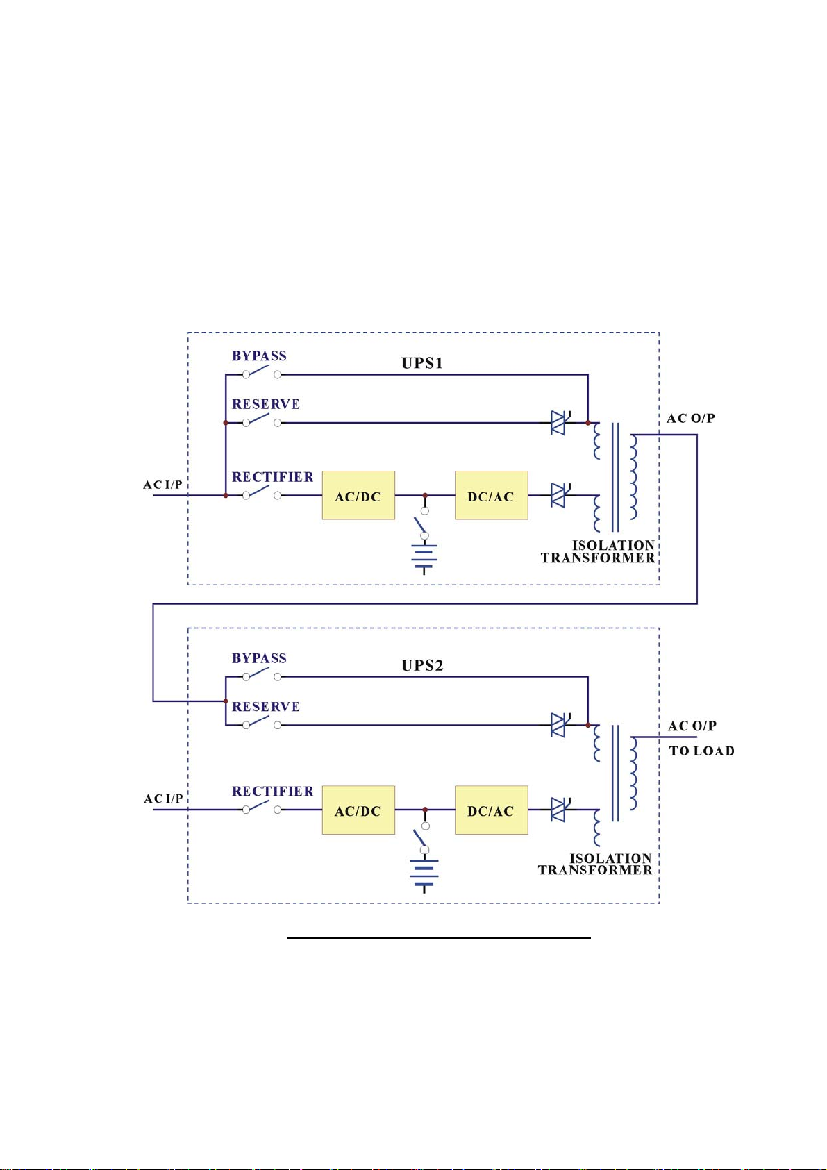
8-1
8. REDUNDANCY
Redundancy can be roughly divided in two types: serial (hot standby) redundancy
and parallel (active) redundancy. DS-C33 series adopts mainly the serial
redundancy.
8.1. Serial Redundancy
ONE TO ONE SERIAL REDUNDANCY
The serial (hot standby) redundancy consist of two UPS with one UPS’s (UPS1)
connect to the reserve/bypass input of the other UPS (UPS2). See in the above
figure.
Page 75

8-2
The two UPSs are running in normal mode currently under normal conditions.
When one of them has problem, the load will still has protection from inverter
and battery. If UPS1 fail and UPS2 is running normally, the load is unaffectedly
supplied from UPS2. If UPS2 fail and UPS1 is running normally, UPS2 will
transfer the load to UPS1 and the load will continue to be protected by inverter
and battery of UPS1. If both of them are running normally, UPS2 takes up all load
and UPS1 bears no load. Therefore, UPS1 has a longer MTBF than UPS2 (can be
interchanged after a period of time), and their MTBF multiple to a large MTBF.
This type of redundancy is employed most frequently. Besides, when mains fail,
UPS2 is the first to contribute its battery to back-up the load, and when UPS2’s
battery is exhausted, the load will be transferred to UPS1, and now UPS1 start to
contribute its battery. Therefore, this topology can make full use of the battery.
The user will not feel wasting money in buy two UPS, for he get a system that has
double protection and double back-up time.
Another cheaper solution (see the figure next page) is if your load is separated,
you intended to install two UPSs with the same power; you can buy another UPS
as redundancy to two UPSs. The reason is that it is
very
rare that both UPSs
(UPS2 & UPS3) breakdown at the same time. Therefore, UPS1 can be a hot
standby UPS to two UPSs.
Anywhere, this topology already makes full use of its resources to contribute the
best protection and longest MTBF.
Page 76

8-3
ONE TO TWO SERIAL REDUNDANCY
NOTE: It is easy and simple to connect our UPS in serial
redundancy.
Page 77
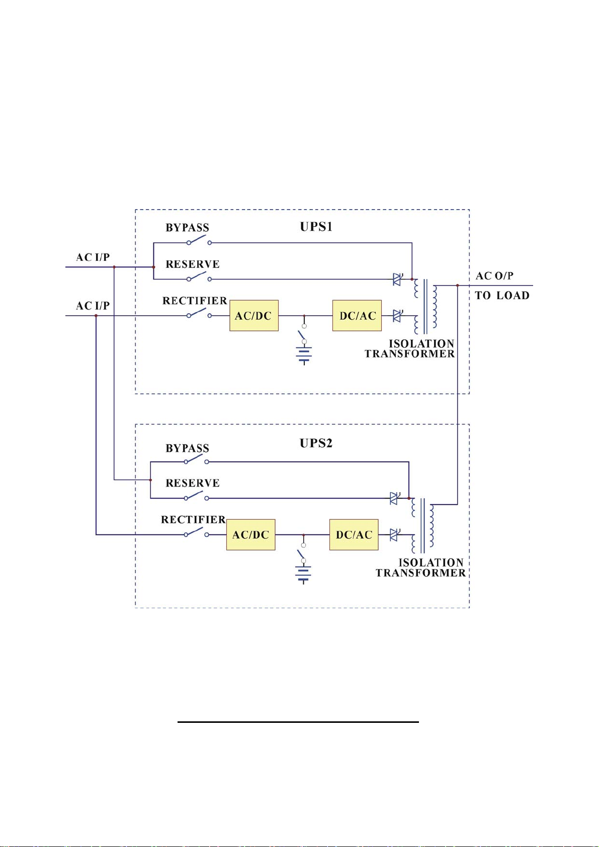
8-4
8.2. Parallel Redundancy
In order to provide more capacity for loads and backup time, we can use the parallel redundancy
operation. (Please refer to the following diagram.) Only 1 UPS can be connected in the parallel
redundancy operation. Parallel Control PCB has been integrated into CPU, so there is no extra
control unit needed.
ONE TO ONE PARALLEL REDUNDANCY
Page 78

9-1
9. HELP
Abnormal
(1) AC input is
right, but
rectifier does
not operate and
RECT AC
FAIL LED
lights up.
(2) The UPS
shutdown
under AC
mains failure.
Description & Checkpoint
The rectifier breaer has not switch on.
The input voltage is not correct (out of the
normal range).
The phase sequence of AC input is
incorrect, input rotation error, and the
LCD will display warning message ‘RECT
PHASE ERROR’ in the STATUS/WARN
menu (MAIN menu → SELECT menu →
STATUS/WARN menu). ROTATION
ERROR LED on left side of the front
panel will lit up too.
If the abnormal cannot be improved as the
aforesaid solution action has been taken.
The battery fuse (breaker/holder/disconnector) has not been closed.
Solution
Switch on the rectifier
breaker.
Connect the right AC
source.
Correct the R.S.T. phase
sequence. Generally, to
exchange any two phases
connection can solve this
problem.
Refer to PCB LED
Detecting Guide and check
the 3C PCB.
Close the battery fuse
breaker/holder/disconnector.
(3) No power
supply for UPS
control circuit
while LCD
cannot display.
The reserve breaker has not been closed
(switched on).
3B PCB has problem.
Close the reserve breaker.
Refer to PCB LED
Detecting Guide and check
the 3B PCB.
Page 79

9-2
Abnormal
(4) The voltage
difference
between
NEUTRAL and
GROUND
become
abnormally
higher﹖
(5) The
inverter cannot
start up.
Description & Checkpoint
There is external wiring error of R.S.T
phase and N. G. instead of UPS unit
itself,.
Apart from INVERTER SS LED in left
side of the front panel, there is other ones
still illuminate.
Switch on the inverter before DC bus has
been established completely. Normally, it
takes around 30 seconds to establish the
DC BUS since the reserve and rectifier
breakers are closed.
Solution
Correct the external wiring
system.
Do trouble shooting
according to the LED
instruction.
Refer to the switch on
procedure. Close the reserve
and rectifier breakers and
wait around 30 seconds or
directly use batteries to
establish the DC bus.
Bypass breaker has been closed (switched
Open the bypass breaker.
on).
The output is overloaded. The LCD will
display warning message ‘ XXX%
Decrease the load to under
the UPS’s rated power.
OVERLOAD’ in the STATUS/WARN
menu (MAIN menu → SELECT menu →
STATUS/WARN menu). XXX%
OVERLOAD LED on left side of the
front panel and OVERLOAD LED on
right side will lit too.
In P&P modules1, the temperature sensor
sockets on 3G PCB and hest sink are not
Take out the P&P module
and connect them properly.
connected properly. WARNINGLED of
FUSE/TEMP still illuminate but LED in
3G PCB doesn’t, indicating DC BUS may
be over 240VDC.
Page 80

9-3
Abnormal
(6) Fans cannot
work while
UPS is on.
(7) The
rectifier shunt
down and
HIGH DC LED
lit up.
(8) Abnormal
voltage in
reserve.
Description & Checkpoint
The fuses positioned behind PCB holder
have been blown or are not installed well.
Abnormal voltage output in R phase.
Voltage limit function failure in the 3B,
which contributes to the DC voltage
becomes over 430V.
3C PCB has problem.
RESERVE AC FAIL LED lights up. LCD
menu also displays the abnormal voltage
in reserve. (REAL TIME DATA menu →
RESERVE DATA menu).
Solution
Replace the fuses or install
them well.
Refer to PCB LED
Detecting Guide and check
the 3T PCB of R phase.
Refer to PCB LED
Detecting Guide and check
the 3B PCB.
Refer to PCB LED
Detecting Guide and check
the 3C PCB.
Check the reserve wiring
and connect with the right
source.
Fuse has blown in 3A PCB
If the abnormal cannot be improved as the
aforesaid solution action has been taken.
Replace the fuse.
Refer to PCB LED
Detecting Guide and check
the 3A PCB.
(9) Abnormal
frequency in
reserve.
RESERVE FREQ FAIL LED lights up.
LCD menu also displays the abnormal
voltage in reserve. (REAL TIME DATA
Check the reserve wiring
and connect with the right
source.
menu → RESERVE DATA menu).
Fuse has blown in 3A PCB
If the abnormal cannot be improved as the
aforesaid solution action has been taken.
Replace the fuse.
Refer to PCB LED
Detecting Guide and check
the 3A PCB.
Page 81

9-4
Abnormal
(10) The
inverter shut
down during
running while
the FAULT
LED lit and
buzzer beeps
continuously.
Bypass breaker has been closed (switched
on).
The output is short-circuited, including
the load itself.
Description & Checkpoint
Solution
Open the bypass breaker
then the inverter will restore
running automatically.
Clear the short circuit at the
output, then switch off the
inverter.
Secondly, switch on once
more to restart the inverter.
The output is overloaded. The LCD will
display warning message ‘ XXX%
OVERLOAD’ in the STATUS/WARN
menu (MAIN menu → SELECT menu →
Decrease the load to under
the UPS’s rated power then
the inverter will restore
running automatically.
STATUS/WARN menu). XXX%
OVERLOAD LED on left side of the
front panel and OVERLOAD LED on
right side will lit too.
Heat Sink is over temperature.
WARNING LED of FUSE/TEMP still
illuminates.
Decrease the load to under
the UPS’s rated power, then
switch off the inverter.
Secondly, switch on once
more to restart the inverter.
IBGT-protect fuse has blown in P&P
module1 or IGBT damage.
When in battery back-up mode, the
inverter shut down due to battery low
(lower than 295VDC).
Take out the P&P module
and replace fuse or IGBT.
Within 30 minutes, the
inverter will restore running
automatically once the AC
main is back.
The Emergency Switch has been
triggered.
Switch off the inverter first
then on once more to restart
the inverter.
Page 82

9-5
Abnormal
(11)
Transferring
failure
between
reserve and
inverter.
Description & Checkpoint
DC BUS voltage becomes abnormal
during transferring. DCV value can be
read in LCD menu.
3P PCB has problem.
LED A4(OTF) in the 3A PCB lit up.
In P&P modules, the temperature sensor
sockets on 3G/3P PCB and hest sink are
not connected properly. WARNING LED
of FUSE/TEMP still illuminates.
Phase sequence error of output
transformer.
If the abnormal cannot be improved as the
aforesaid solution action has been taken.
Solution
Take out the P&P module 2
and make sure the SCR
drive connection is OK.
Refer to PCB LED
Detecting Guide. Take out
the P&P module 2 and
check the 3P PCB.
Refer to PCB LED
Detecting Guide and check
the 3G PCB.
Take out the P&P module
and connect them properly.
Change the transformer
wiring.
Refer to PCB LED
Detecting Guide and check
the 3G and 3P PCB.
(12) Phase lack
when AC
The mimic output LED in the front panel
blinks.
output.
Fuse has blown in 3T PCB
If the abnormal cannot be improved as the
aforesaid solution action has been taken.
Make sure the signal sockets
in 3T PCB are connected
properly.
Replace the fuse.
Refer to PCB LED
Detecting Guide and check
the 3T PCB.
(13) The
Batteries become worn out or damaged.
Replace batteries.
mimic battery
LED in the
front panel
blinks.
Page 83

9-6
Abnormal
(14) All LED
in the front
panel light up.
(15)
Communicatio
n interface is
not good.
Description & Checkpoint
CPU inserting error in 3A or 3R PCB
Communication cables are connected
improperly.
Communication software is not installed
successfully.
Communication port setup error.
CPU inserting error in 3R PCB.
If the abnormal cannot be improved as the
aforesaid solution action has been taken.
Solution
Insert the CPU into right
socket.
Correct the wiring.
Reinstall the software.
Correct the setup.
Insert the CPU into right
socket.
Refer to PCB LED
Detecting Guide and check
the 3R PCB.
 Loading...