

Page 1
Page 2

Table of contents
1.0 Preface ---------------------------------------------------------------------------------------- 1-1
1-1 Introduction ----------------------------------------------------------------------------1-1
1-2 Safety Note and Precaution ----------------------------------------------------------1-2
2.0 System structure -----------------------------------------------------------------------------2-1
2-1 System Diagram of DS-C33 ---------------------------------------------------------2-1
2-2 System assembly and parts layout--------------------------------------------------- 2-2
2-3 Introduction on function of main module ------------------------------------------ 2-3
2-4 System operation mode--------------------------------------------------------------- 2-4
3.0 Panel function-------------------------------------------------------------------------------- 3-1
3-1 Status indication on LED panel------------------------------------------------------ 3-1
3-2 Function Key---------------------------------------------------------------------------3-2
3-3 LCD Panel description---------------------------------------------------------------- 3-3
4.0 Placement and installation------------------------------------------------------------------ 4-1
4-1 Placement------------------------------------------------------------------------------- 4-1
4-2 Installation------------------------------------------------------------------------------4-2
5.0 Operation procedure------------------------------------------------------------------------- 5-1
5-1 Start up procedure --------------------------------------------------------------------- 5-1
5-2 Shut down procedure------------------------------------------------------------------ 5-2
5-3 Maintenance procedure--------------------------------------------------------------- 5-3
5-4 System recovery from maintenance procedure------------------------------------ 5-4
5-5 Introduction to LCD front panel and illustration of each function-------------- 5-5
5-6 Emergency shut down procedure----------------------------------------------------5-6
6.0 Maintenance---------------------------------------------------------------------------------- 6-1
7.0 Specifications -------------------------------------------------------------------------------- 7-1
8.0 DS-C33 Series troubleshooting------------------------------------------------------------ 8-1
8-1 Simple troubleshooting for rectifier/charger--------------------------------------- 8-1
8-2 Simple troubleshooting for Inverter-------------------------------------------------8-2
8-3 Simple troubleshooting for system function --------------------------------------- 8-3
Page 3

1 Preface
1-1 Introduction
DS-C33 series UPS is one of the industry’s most reliable and stable power protection equipment. It is
fully controlled by DSP (Digital Signal Processor) to ensure high performance and worry free operation
in protecting your valuable equipment from power disturbances. This makes the DS-C33 series UPS
fully compatible for use in computer, precision instrument, banking, manufacturing, and other mission
critical applications.
1-2 Safety Note and Precaution
Please note and refer to warning marks which you will find in the unit.
Don’t touch Risk of electrical shock
Areas with the “Risk of electrical shock” mark indicate 410VDC high voltage. Do not touch the
parts with this mark.
Page 4
2 System structure
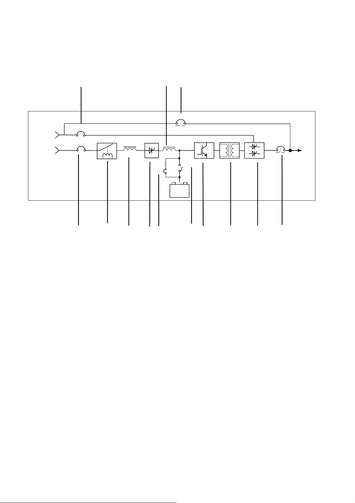
2-1 System Diagram of DS-C33
(12) (5) (7)
S6
S2
Utility 2
S3
Utility 1
S5
Load
Battery
Pack
S4
+
S1
(1) (2) (3) (4) (13) (6) (8) (9) (10) (11)
fig. 2-1
(1) Main power switch (S3)
(2) Input protection
(3) Three phase alternating current power inductor
(4) Rectifier / battery charger module
(5) Direct current power inductor
(6) Battery fuse switch (S4)
(7) Manual bypass switch (S6)
(8) Inverter module
(9) Isolation transformer
(10) Static switch module
(11) Output switch (S5)
(12) Bypass power switch (S2)
(13) Start up auxiliary switch (S1)
Note :
(1)The UPS input can be powered from a single utility source or by dual utility sources.
(2)Dual utility input is optional.
Page 5
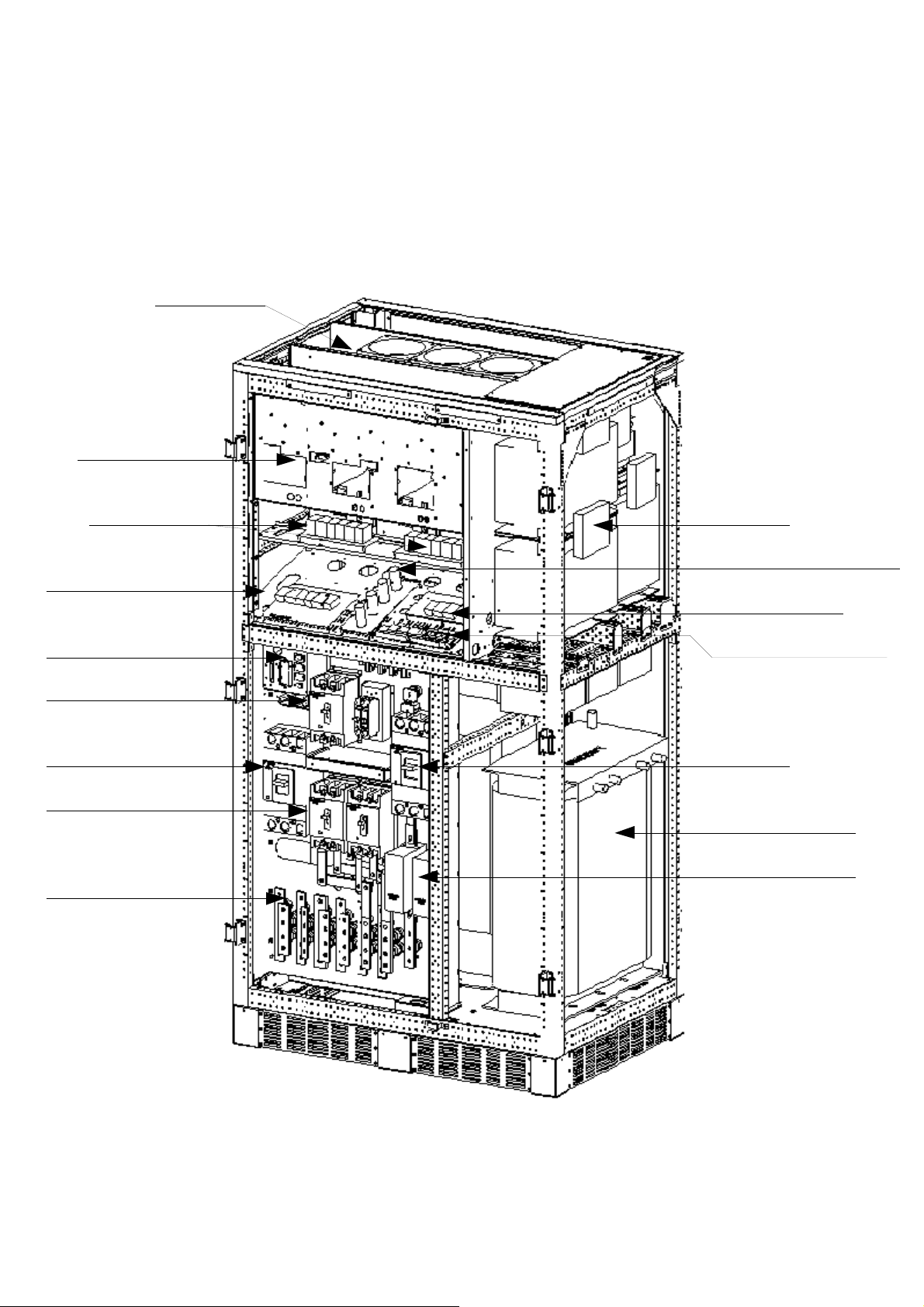
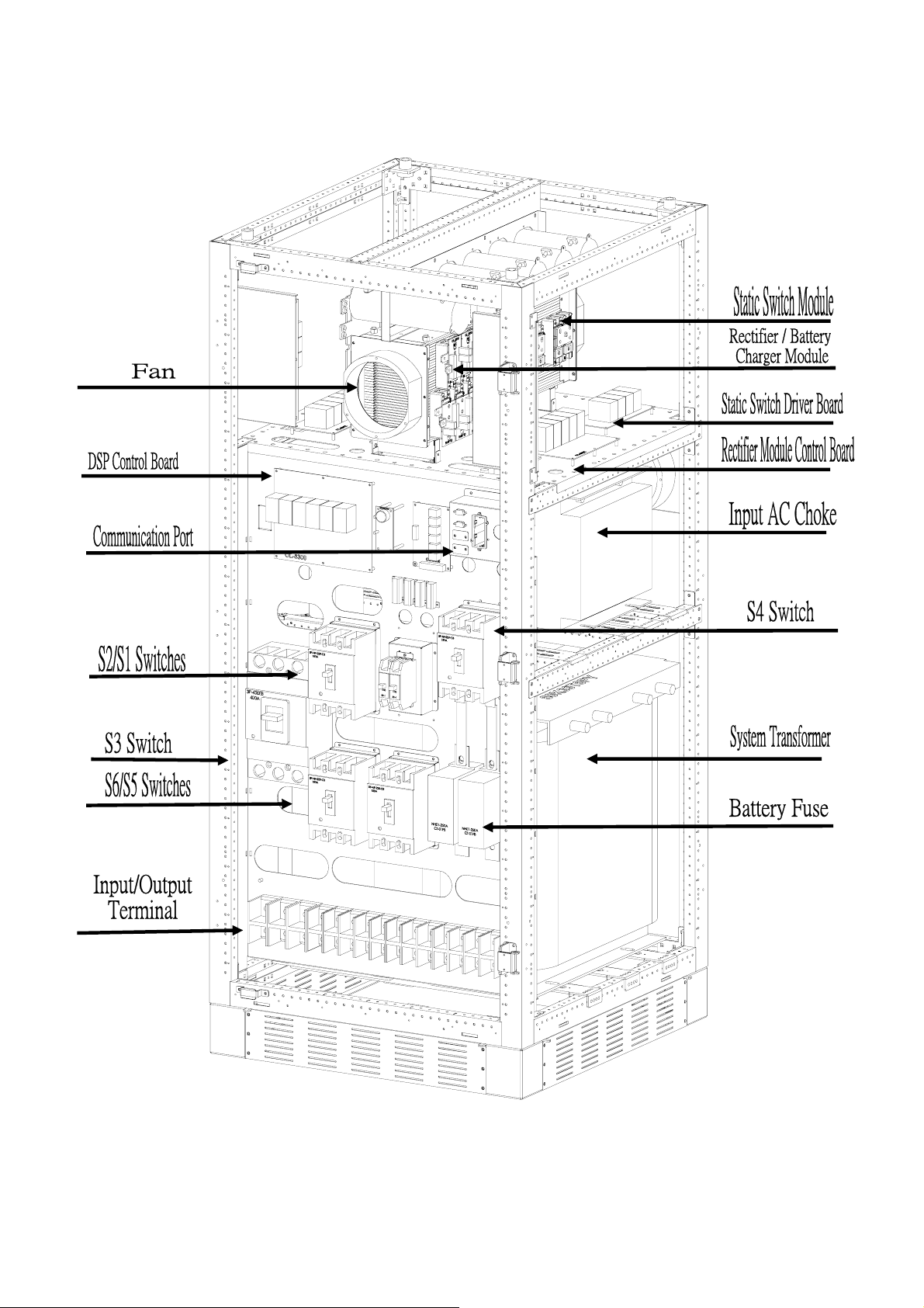
2-2 System assembly and parts layout
h
Drawings 2-2A and 2-2B are the assembly diagrams of DS-C33 series 100K, 120K
Fan
INV Module
INV/Driver Board
DSP Control Board
Communication Port
S2/S1 Switch
S3 Switch
S6/S5 Switch
Input/Output
Terminal
Input AC Choke
AC Power Sensor Board
System Power Board
AS-400 Interface Card
S4 Switc
System Transformer
S4 Battery Fuse
Fig. 2-2A
Page 6
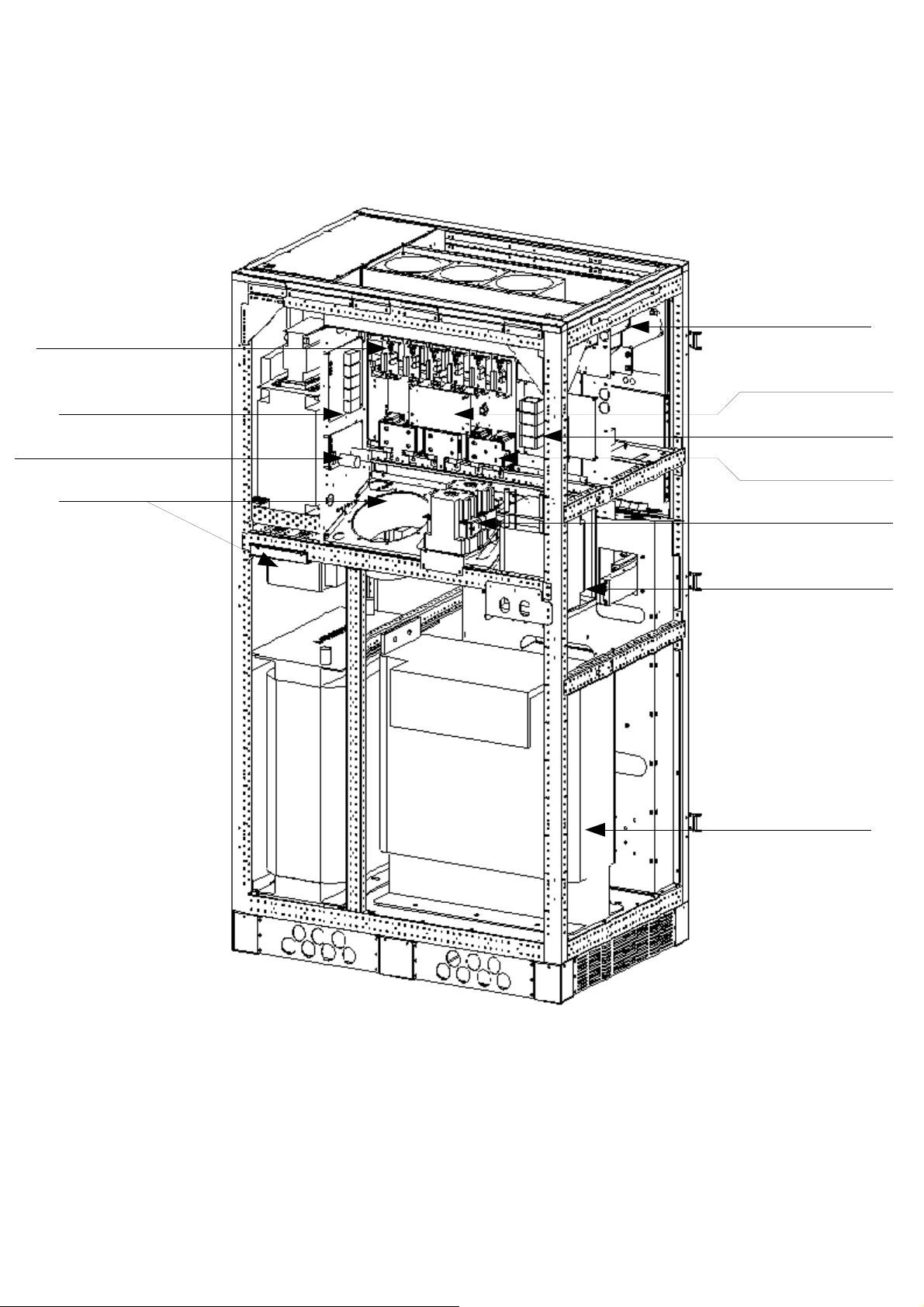
Rectifier/Charger Module
DC Capacitance
Rectifier/Charger
Control Board
12 Pluse Power Sensor Board
Fan
Static Switch Control Board
Input Relay Power Board
Static Switch Module
Input Relay Module
DC Choke
INV Transformer
Fig. 2-2B
Page 7
Drawings 2-2C and 2-2D are the assembly diagrams of DS-C33 series 45K, 60K, 80K
Fig. 2-2C
Page 8
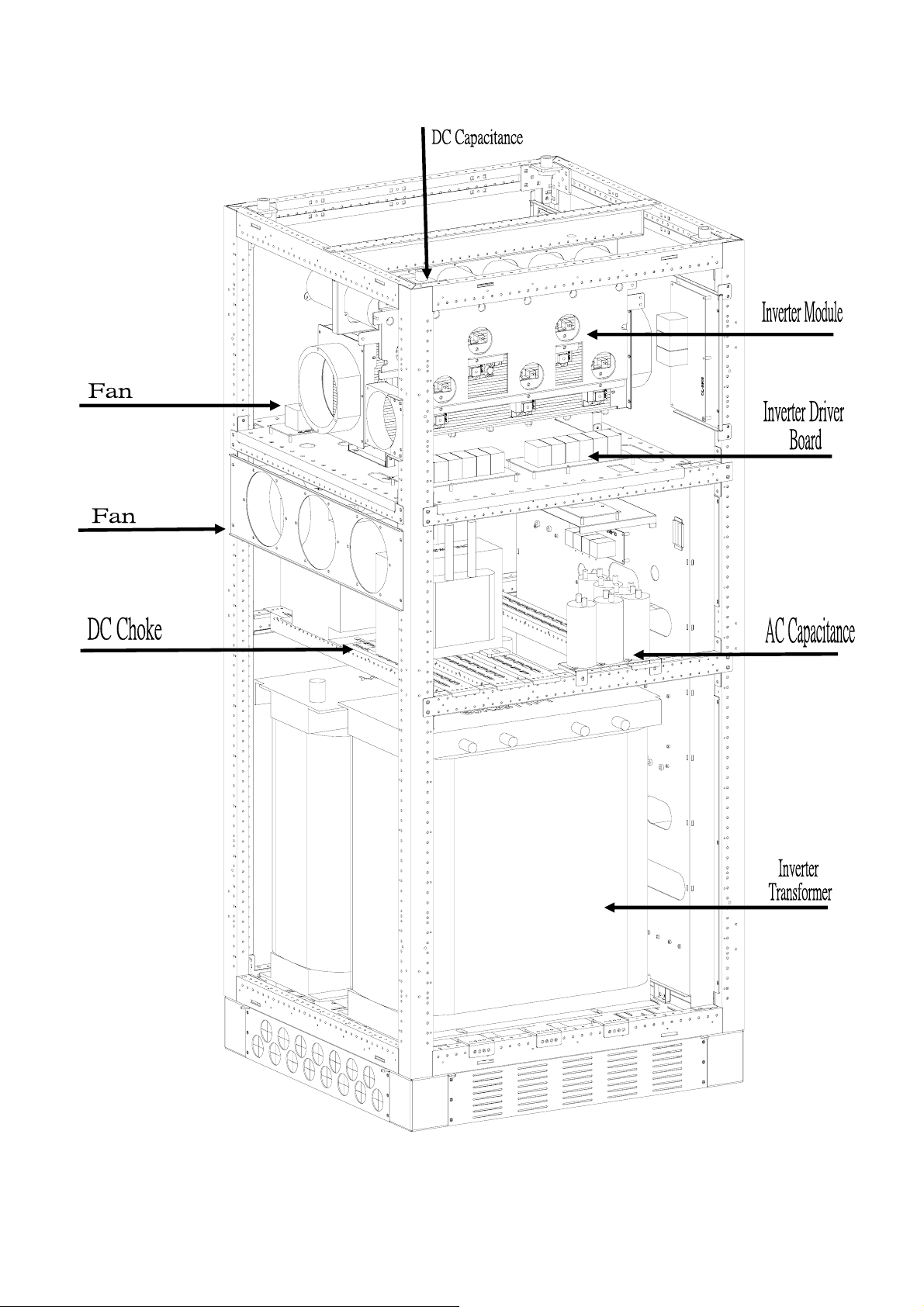
Fig. 2-2D
Page 9

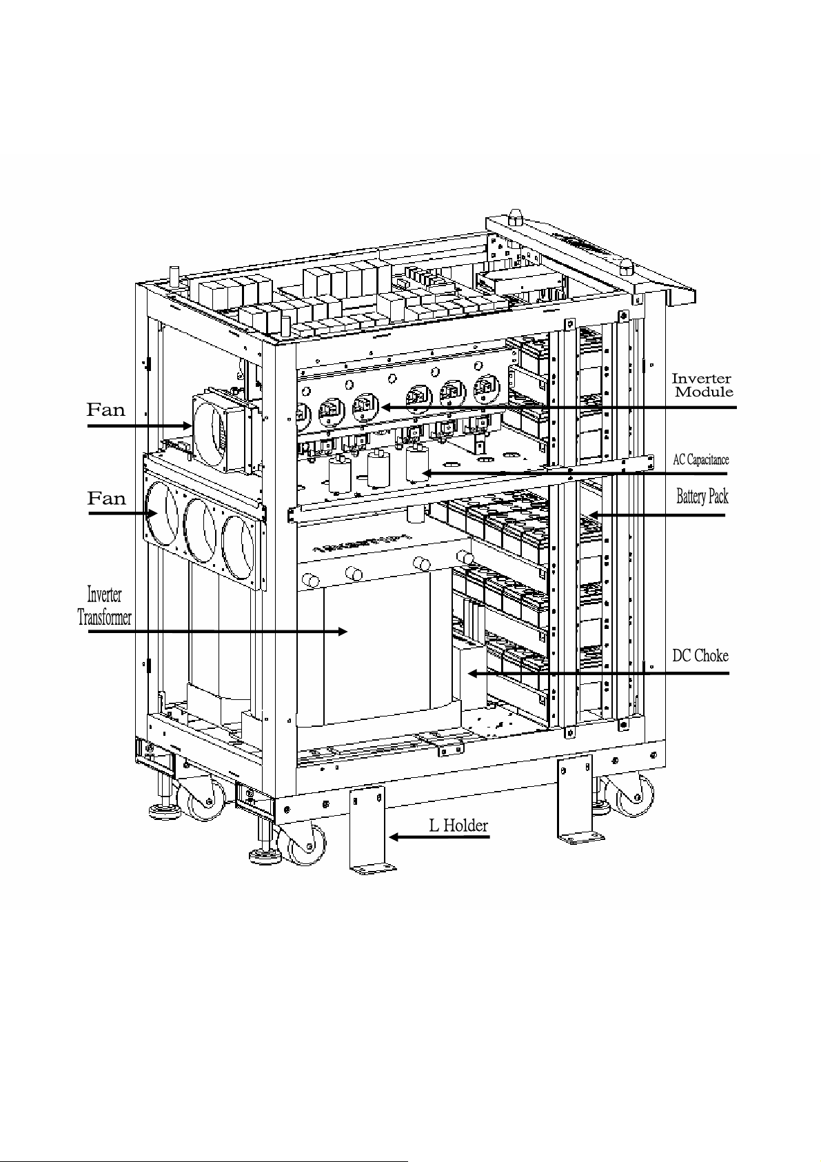
Drawings 2-2E and 2-2F are the assembly diagrams of DS-C33 series 22.5K, 30K.
Fig. 2-2E
Page 10
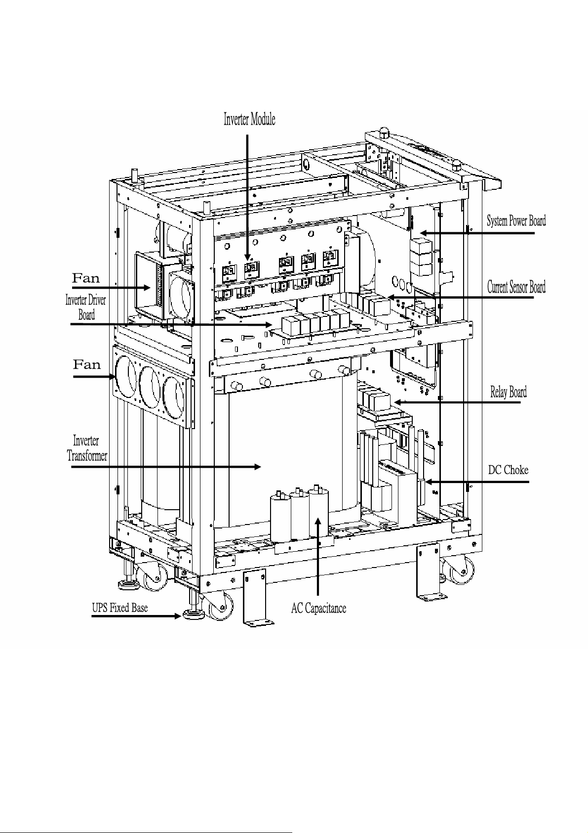
Fig. 2-2F
Page 11
Drawings 2-2G and 2-2H are assembly diagrams of DS-C33 series 10K&15K
Fig. 2-2G
Page 12
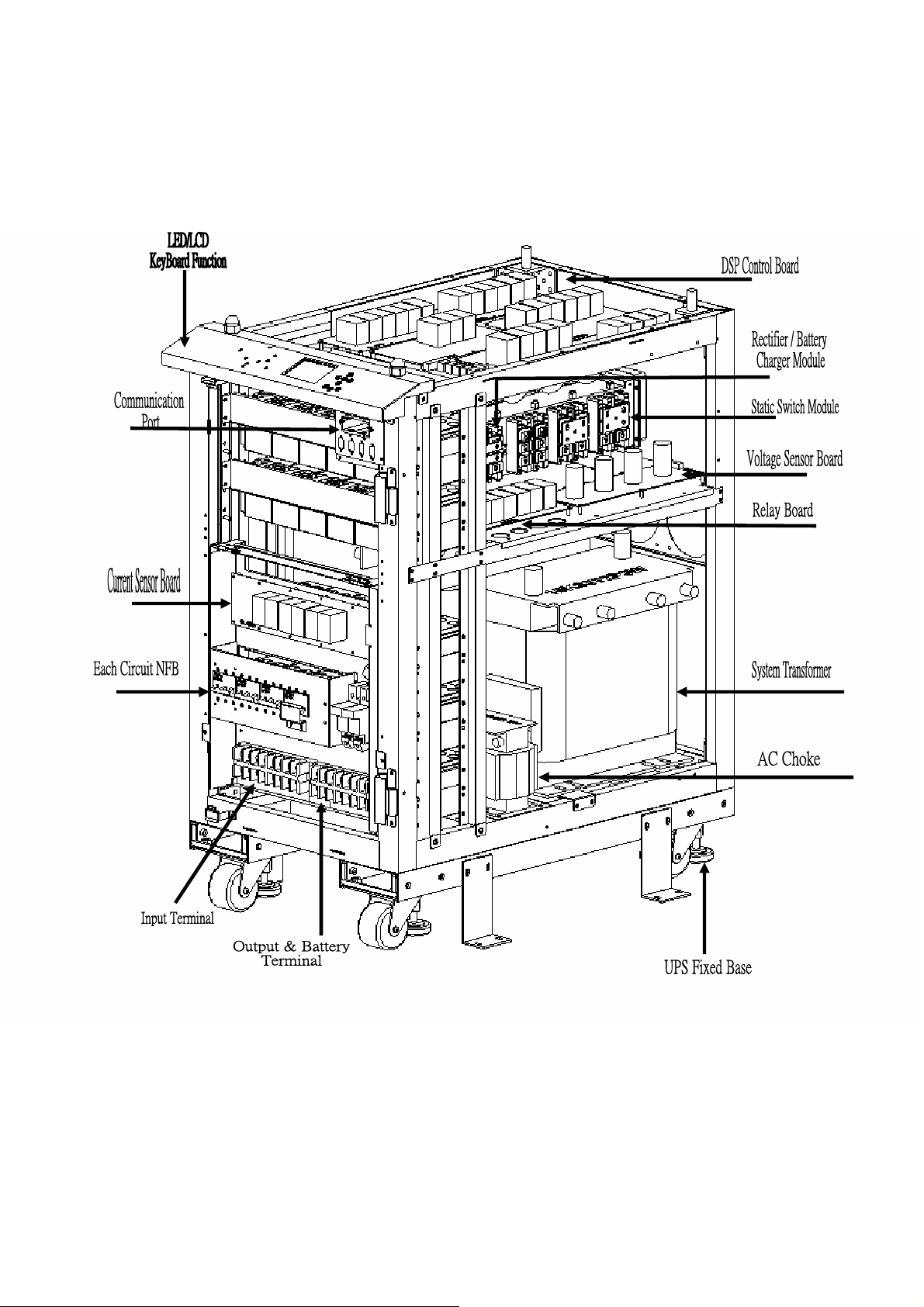
Fig. 2-2H
Page 13
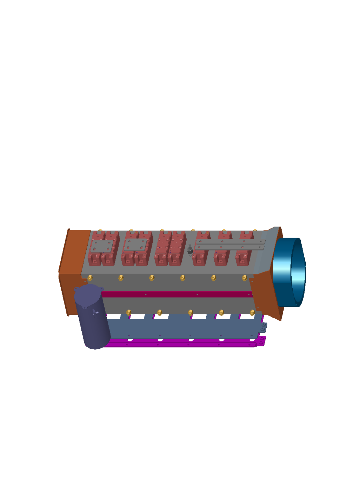
2-3 Introduction on function of main module
2-3-1 Rectifier / battery charger
(1) Rectifier / battery charger module is using SCR components for transforming AC to DC voltage
and to recharge the batteries.
(2) In Rectifier / battery charger module, double control method to CPLD and DSP are combined to
keep rectifier and battery charger more steady and reliable.
(3) Has complete system for protection from over voltage.
(4) Detection on phase sequence error or single phasing.
(5) Equipped with function to soft start the DC voltage during power up or return of utility power.
(6) Designed with 3 phases and 6 pulses. Optional six phase 12 phase pulse is available.
(7) It supports float charge and equalization charge for maintenance free battery. Floating charge
voltage is DC 420V, equalization charge voltage is DC 430V, floating charge voltage is 410V.
(8) It can conduct self test even in on line mode.
(9) Charging current is controlled by LCD panel setting.
Fig. 2-3-1(actual model assembly diagram)
Page 14
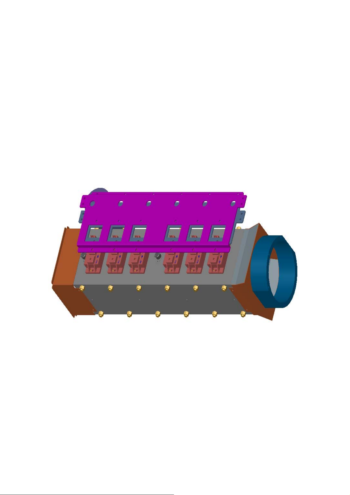
2-3-2 Introduction to inverter module
(1) Uses IGBT as power component.
(2) Uses high technology DSP to control the inverter module.
(3) Utilize digital control management to prevent discrete component from aging, temperature slant
and reduce the quantity of parts to enhance system reliability.
(4) Integrated A/D signal processing, 12bit resolution and high speed transferring capability.
(5) Reserve communication port for parallel UPS operation, detection of secondary power, ATS
control signal, SPWM testing port.
(6) Highly integrated system, compact and highly reliable.
(7) It is works in coordination with the rectifier, AS-400 interface board, IGBT driver, static switch,
LCD panel, PT board, CT board to convert the utility voltage into clean power.
Fig. 2-3-2 (Inverter module)
2-3-3 Static switch
(1) Uses SCR components as switching circuit between INV and BYPASS. These are controlled
using high frequency electrical technique.
(2) Use high frequency technique to isolate the trigger circuit to prevent false triggering of the
SCR.
(3) DSP control keeps it energized and provides switching signal to connect either bypass or
inverter output to the load.
(4) Assembly model diagram is shown in fig. 2-3-1.
(5) Notice: static switch module and inverter module are mounted in the same heat sink.
Page 15
2-3-4 Input start up/protect trigger
(1) Start up function. This function is used for delaying the input power during start up or utility
recovery to protect the unit from electrical surge impact. The function is controlled by the main
control board.
(2) Protection function. This function is used whenever input voltage is too high or too low or
wrong phase sequence or if one phase is missing. In this case, the input trigger will be cut to
protect the unit. This function is controlled and detected by main control board.
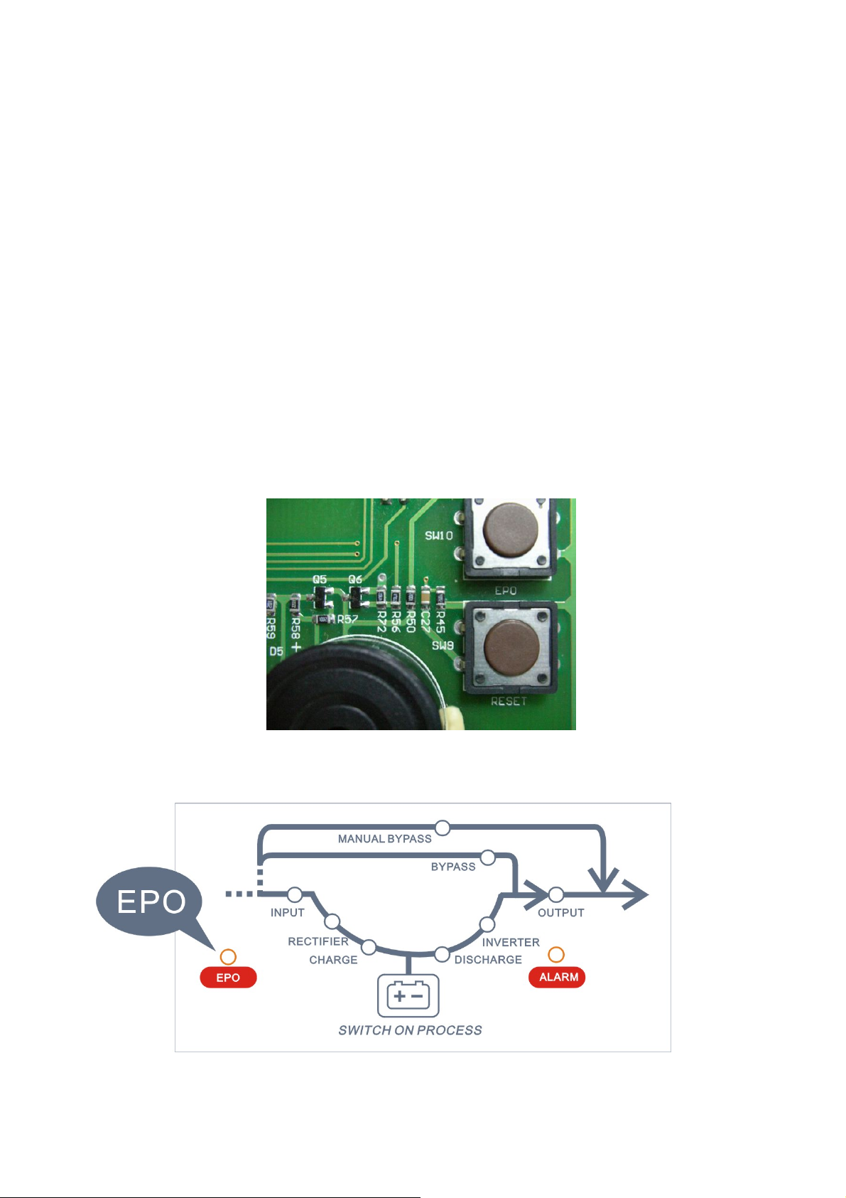
2-3-5 EPO switch (Emergency Power Off)
(1) EPO (Emergency Power Off) is a device for shutting down the UPS in case of emergency. By
pressing the EPO button, the UPS can be shut down immediately. When the UPS has been shut
down, all system will be locked and all status are stop. If you want to restart the system, press
“OFF” button on the front panel and then press “Enter” , then press “ON” button and “Enter” to
restart the inverter.
PCB 3304 :
PCB 3304A :
EPO
Fig. 2-3-5
Fig. 2-3-6
Page 16
2-4 System operation mode
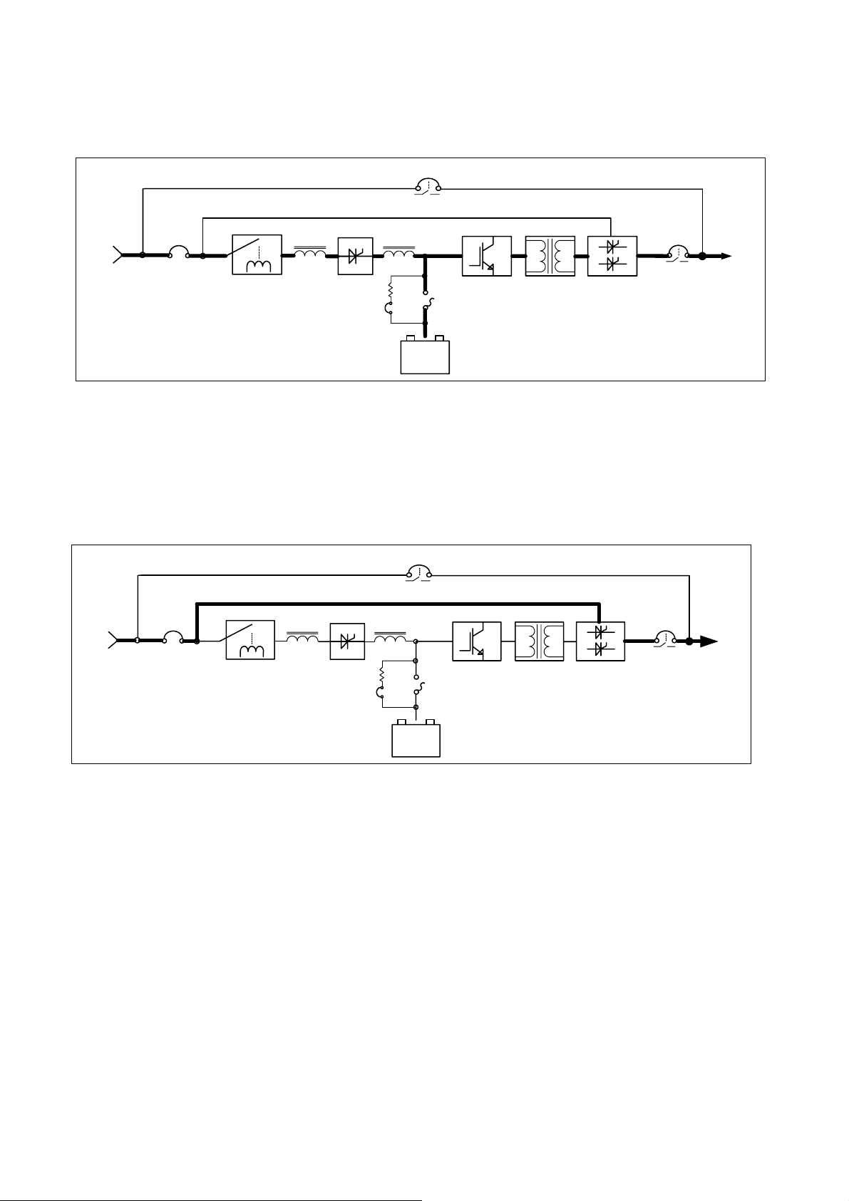
2-4-1 System is normal (Fig. 2-4-1)
S6
Manual bypass switch
AC choke DC choke
Rectifier
S1
Battery
auxiliary
switch
-
Battery
S4
Battery
switch
+
Inverter
Transformer
S.T.S.
S5
Load
Output
switch
Utility
S3
Input
switch
Input
protection
Pack
Fig. 2-4-1
Utility AC input supplies the rectifier /battery charger where the AC is converted into DC. Battery is
recharged while the DC is fed to the inverter module. The static switch module connects the inverter
output to the load while the bypass electricity is blocked. At this time power is supplied by inverter.
2-4-2 System bypass (fig.2-4-2)
S6
Manual bypass switch
AC choke DC choke
Rectifier
S1
Battery
auxility
switch
-
Battery
Pack
S4
Battery
switch
+
Inverter
Transformer
S.T.S.
S5
Load
Output
switch
Utility
S3
Input
switch
Input
protection
Fig. 2-4-2
Utility input AC power supplies the load through the static switch. At this time power is supplied by
the utility.
Page 17

2-4-3 System is powered by battery (fig.2-4-3)
Manual bypass switch
S6
AC choke DC choke
Rectifier
S1
Battery
auxility
switch
-
Battery
Pack
S4
Battery
switch
+
Inverter
Transformer
S.T.S.
S5
Load
Output
switch
Utility
S3
Input
switch
Input
protection
Fig. 2-4-3
In the absence of the utility input, the rectifier stops and DC power is supplied by the batteries to the
inverter module. The inverter converts the DC into AC. The static switch connects the inverter
output to the load. At this time, the inverter supplies the load. When power is supplied by the batteries,
the back up time depends on number of batteries and load level.
2-4-4 System Diagram for manual maintenance bypass mode (shown as fig. 2-4-4)
S6
Manual bypass switch
AC choke DC choke
Rectifier
S1
Battery
auxility
switch
-
Battery
S4
Battery
switch
+
Inverter
Transformer
S.T.S.
S5
Load
Output
switch
Utility
S3
Input
switch
Input
protection
Pack
Fig. 2-4-4
Utility AC input flows through the manual maintenance switch directly to the output load. At this time
power is supplied by utility. In this mode, a technician can repair or maintain and clean the UPS.
Page 18

2-4-5 EPO switch (fig. 2-4-5)
S6
Manual bypass switch
AC choke DC choke
Rectifier
S1
Battery
auxility
switch
-
Battery
S4
Battery
switch
+
Inverter
Transformer
S.T.S.
S5
Load
Output
switch
Utility
S3
Input
switch
Input
protection
Pack
Fig 2-4-5
Be sure the to check if the EPO is switch otherwise it will not be possible to start up the UPS and no
voltage will be supplied to the output load.
Page 19

3 Panel function
3-1 Status indication on LED panel (Fig. 3-1 and Fig 3-2)
←Key
→ Key
ON Key
↑ Key
↓ Key
ESC Key
ENTER Key
Fig. 3-1
Fig. 3-2
Page 20

Status indication on LCD/LED panel is divided into 4 modes:
(1) System Normal mode: In this mode, only INPUT, RECTIFIER, CHARGE, INVERTER, OUTPUT
LEDs are illuminated and others LEDs are off.
(2) System Bypass mode: INPUT, BYPASS and OUTPUT LEDs are illuminated and others are off.
(3) Back-up mode: DISCHARGE, INVERTER and OUTPUT LEDs are illuminated and others are off.
(4) Manual Bypass mode: When Switch S6 is switched to “ON” position, Only MANUAL BYPASS
LED is on, others are off. It means that the system has transferred to Manual Bypass mode correctly.
After S1, S2, S3 and S4 are switched “OFF”, use a discharging tool to release the remaining voltage
on the DC capacitor. When the MANUAL BYPASS LED is extinguished, proceed to execute
maintenance operation.
3-2 Function key
Introduction to function key on the panel
ON button for turning on inverter
OFF button for turning off inverter
← button
→ button
↑ button
↓ button
ESC button Exit from present page
ENTER button for confirming setting
for shifting cursor left
for shifting cursor right
for shifting cursor up or turn to other page
for shifting cursor down or turn to other page
Page 21

3-3 LCD Panel description
(A-1)
Date display
MAIN MENU
A Date display
B Event stories
C System set
D Time display
E Time set
I/P V / I/P Freq.
I/P I / I/P Cap. / Total Cap.
O/P V / O/P Freq.
O/P I / O/P Cap. / Total Cap.
O/P Power / Load Cap.
Bat V, C/C, C/M, Mech. Temp.
(C-1)
SYSTEM SET
(1)Basic set
(2)User set
(E-1)
TIME DISPLAY
2003 / 10 / 21
00: 00 :00
(F-1)
Date/Time Set
Date
200*/**/ **
Time
**: **:**
Page 22

(A-1)
(A-2-1)
Date display
I/P V / I/P Freq.
I/P I / I/P Cap. / Total Cap.
O/P V / O/P Freq.
O/P I / O/P Cap. / Total Cap.
O/P Power / Load Cap.
Bat V, C/C, C/M, Mech. Temp.
(A-2-6)
Bat V:DC 000.0V
Bat C/C :000.0A
Bat C/M:FL
Mech. Temp.:00.0Deg
I/P V
RS 000.0V RN 000.0V
ST 000.0V SN 000.0V
TR 000.0V TN 000.0V
I/P Freq . : 00.0 HZ
(A-2-2)
I/P I I/P Cap.
RN 000.0A 000.00KVA
SN 000.0A 000.00KVA
TN 000.0A 000.00KVA
Total Cap. : 000.00KVA
(A-2-3)
O/P V
RS 380.0V RN 220.0V
ST 380.0V SN 220.0V
TR 380.0V TN 220.0V
O/P Freq. : 60.0Hz
(A-2-4)
O/P I O/P Cap.
RN 000.0A 000.00KVA
SN 000.0A 000.00KVA
TN 000.0A 000.00KVA
Total Cap. : 000.00KVA
(A-2-5)
O/P POWER R 000.00KW
S 000.00KW
T 000.00KW
Total Power 000.00 KW
Load Cap. : 000.00 %
Page 23

(C-1)
SYSTEM SET
Basic set
User set
Please Enter
Security Code
****
YES
NO
(C-3)
USER SET
1 Alter security NO.
2 Battery test
3 Communication set
4 F. V. C/C set
5 Other set
Security code Error
Page 24

(C-3)
(C-4-1)
USER SET
1 Alter security NO.
2 Battery test
3 Communication set
4 F. V. C/C set
5 Other set
ALTER SECURITY NO.
Key in old code
****
Key in new code
****
(C-4-2)
BATTERY TEST
▓ 30 Seconds
□ 1 Month
□ 3 Month
□ Test OFF
(C -4-4)
F. V. C/C SET
1 Frequency set
2 System input V
3 System output V
4 Output voltage
5 Charge current
6 Charger mode
(C-4-5)
OTHER SET
1 Buzzer
2 Backup time
3 Language
4 Model type
Page 25

(C-4-2)
BATTERY TEST
▓ 30 Seconds
□ 1 Month
□ 3 Month
□ Test OFF
SUCCEEDWaiting
SUCCEED
SUCCEED
SUCCEED
Page 26

(C-4-4)
F. V. C/C SET
1 Frequency set
2 System input V
3 System output V
4 Output voltage
5 Charge current
6 Charger mode
FREQUENCY SET
口50HZ
口60HZ
SYSTEM INPUT
V SET
口110V
口220V
SYSTEM OUTPUT
V SET
口110V
口220V
Succeed
Succeed
Succeed
O/P VOLTAGE SET
口110V/220V
口115V/230V
口120V/240V
CHARGE CURRENT
SET
口1A 口10A
口2A 口15A
口3A 口20A
口5A 口30A
CHARGER MODE
6 充 電 機 模 式 設 定
SET
口 FL
口 EQ
Succeed
Succeed
Succeed
Page 27

(C-4-5)
OTHER SET
1 Buzzer
2 Backup time
3 Language
4 Model type
BUZZER SET
口 Silence
口 Alarm
LANGUAGE SET
口 English
口 Chinese
Succeed
Succeed
MODEL SET
口10K 口60K
口15K 口80K
口22.5K 口100K
口30K 口120K
口45k 口150K
Succeed
Page 28

(F-1)
TIME SET
DATE
200*/**/ **
TIME
**: **:**
Date/Time Set
Y / M / D
200*/**/**
H M S
: :
Succeed
Page 29

4 Placement and installation
4-1 Placement
4-1-1 Transporting
The UPS system is composed of the main equipment and battery pack. Therefore be careful when
transporting it and handle it following the points listed below.
(1) Follow the arrow symbol in the carton for the correct position of the UPS. Don’t turn it upside
down or in a slanting position.
(2) It is necessary to fasten the system firmly during transportation.
(3) When transporting, don’t remove the packaging to reduce impact to the system.
(4) When transporting, make sure that the unit does not get wet.
(5) Do not drop and avoid strong impacts to this UPS to protect the components from damage.
4-1-2 Unpacking
Please follow the steps below to unpack the UPS.
(1) Cut the wrapping and remove the packing board.
(2) Remove PE cubicle for protecting the equipment.
(3) Unscrew UPS from the pallet base.
(4) Put a ramp board at the back of the UPS, and let it slide down smoothly.
4-1-3 Position and Environment:
Precaution for storage
(1) Ambient temperature of installation site range form +28℃ to -10℃. Battery life will be
reduced if the ambient temperature exceeds this range. Ideal ambient temperature for operating
the equipment is between +25℃ and 5℃.
(2) Sufficient space must be provided around the equipment to enable maintenance operations. A
space of 1M must be available in front of the equipment and minimum 50cm of space around
the UPS for ventilation.
(3) Table 4-1-3 shows the BTU consumption for DS-33 series.
Model BTU Model BTU
DS10KC33 4819 DS60KC33 28909
DS15KC33 7225 DS80KC33 38546
DS22.5KC33 10841 DS100KC33 48183
DS30KC33 14454 DS120KC33 32640
DS45KC33 21682
Table 4-1-3
(4) It is essential to have sufficient illumination and fire control device in the room where the UPS
Page 30

will be installed.
4-2 Installation
4-2-1 Input / Output Specifications
System output 50Hz/60Hz 3 wire 3 phase wire 200Vac, 220Vac 50Hz/60Hz 3 phase 4 wire and
grounding wire 110/190Vac,115/200Vac,120/208Vac,127/220Vac 220/380Vac,230/400Vac,240/415Vac
System output 50Hz/60Hz 3 phase 4 wire and grounding wire 110/190Vac, 115/200Vac, 120/208Vac,
127/220Vac, 220/380Vac, 230/400Vac, 240/415Vac. The table below shows the UPS input/output
current and switch specifications.
Rating Voltage Input max.
current
110/190V 55A 3P/60A 38A 3P/50A 65A
10KVA
15KVA
22.5KVA
30KVA
120/208V 49A 3P/50A 35A 3P/40A 60A
220/380V 28A 3P/30A 19A 3P/20A 32A
110/190V 82A 3P/100A 57A 3P/75A 98A
120/208V 74A 3P/75A 52A 3P/60A 90A
220/380V 39A 3P/40A 28A 3P/30A 48A
110/190V 122A 3P/125A 85A 3P/100A 147A
120/208V 114A 3P/125A 78A 3P/80A 135A
220/380V 62A 3P/80A 43A 3P/60A 74A
110/190V 163A 3P/175A 113A 3P/125A 195A
120/208V 149A 3P/150A 104A 3P/125A 180A
220/380V 83A 3P/100A 57A 3P/75A 98A
Input circuit
breaker
Out max
current
Output
circuit
breaker
Neutral wire
max. current
110/190V 239A 3P/300A 170A 3P/200A 294A
45KVA
60KVA
80KVA 220/380V 211A 3P/225A 149A 3P/150A 263A
100KVA 220/380V 242A 3P/300A 189A 3P/200A 327A
120KVA 220/380V 291A 3P/300A 227A 3P/225A 393A
150KVA 220/380V 364A 3P/400A 284A 3P/300A 491A
200KVA 220/380V 485A 3P/500A 378A 3P/400A 654A
250KVA 220/380V 598A 3P/600A 473A 3P/500A 819A
120/208V 223A 3P/225A 156A 3P/150A 270A
220/380V 121A 3P/125A 85A 3P/100A 147A
110/190V 312A 3P/350A 226A 3P/225A 391A
120/208V 290A 3P/300A 208A 3P/225A 360A
220/380V 158A 3P/175A 114A 3P/125A 197A
Page 31

Table 4-2-1
When installing the UPS, please refer to table of 4-2-1 for corresponding input/output circuit breaker.
Refer to table 4-2-2 for wire specifications and capacity
Insulating Wire
Acceptable highest temperature of insulating
1 PVC wire
2 RB wire
3 Heatproof PVC wire
4 PE Wire
5 SBR Wire
6 Artificial rubber wire
7 EP rubber wire
8 Cross connect PE wire
Ampere capacity for every kind wire(ambient temperature 35℃)
Copper
number
60℃insulation 75℃insulation 80℃insulation 90℃insulation
wire
conducting wire
SWG AWG
diameter
Ampere capacity (A)
2.0 14 7/0.6 20
3.5 12 7/0.8 30
materials
60℃
75℃
80℃
90℃
Wiring
5.5 10 7/1.0 40
8 8 7/1.2 55 65 70 80
14 6 7/1.6 80 95 100 110
22 4 7/2.0 100 125 135 145
30 7/2.3 125 150 160 170
38 2 7/2.6 145 180 190 205
50 19/1.8 175 210 220 245
60 0 19/2.0 200 240 250 280
80 19/2.3 230 285 300 330
100 19/2.6 270 330 350 380
125 19/2.9 310 380 400 440
150 37/2.3 360 440 460 505
200 37/2.6 425 520 550 600
250 61/2.3 505 615 650 710
325 61/2.6 590 720 760 830
400 61/2.9 680 825 870 995
500
61/3.2 765 930 985 1080
Page 32

Table 4-2-2A
For wire diameters for different capacity of UPS system, please check the table 4-2-2B below
Wire diameter of ground wire
10KVA 8mm2
15KVA 8mm2
22.5KVA 8mm2
30KVA 14mm2
45KVA 22mm2
60KVA 22mm2
80KVA 38mm2
100KVA 38mm2
120KVA 38mm2
Table 4-2-2B
Page 33

4-2-3 Input/Output connection and precaution
From table 4-2-1 and table 4-2-2, we could determine the installation wire diameter and breaker
capacity, as shown below.
Rating Mains voltage Input circuit
breaker
10KVA
15KVA
22.5KVA
30KVA
110/190V
120/208V
220/380V
110/190V
120/208V
220/380V
110/190V
120/208V
220/380V
110/190V
120/208V
220/380V
110/190V
3P/60A
3P/50A
3P/30A
3P/100A
3P/75A
3P/40A
3P/125A
3P/125A
3P/80A
3P/175A
3P/150A
3P/100A
3P/300A
Input wire
diameter (mm2)
14
14
5.5
22
22
8
38
38
22
50
50
22
100
Output circuit
breaker
3P/50A
3P/40A
3P/20A
3P/75A
3P/60A
3P/30A
3P/100A
3P/80A
3P/60A
3P/125A
3P/125A
3P/75A
3P/200A
Output wire
diameter (mm2)
14
14
5.5
14
14
8
22
22
14
38
38
22
60
45KVA
60KVA
80KVA 220/380V
100KVA 220/380V
120KVA 220/380V 3P/300A 150 3P/250A 80
150KVA 220/380V 3P/400A 200 3P/300A 150
200KVA 220/380V 3P/500A 225 3P/400A 200
250KVA 220/380V 3P/600A 250 3P/500A 225
120/208V
220/380V
110/190V
120/208V
220/380V
3P/225A
3P/125A
3P/350A
3P/300A
3P/175A
3P/225A
3P/300A
60
38
125
100
60
60
150
Tab. 4-2-3
3P/150A
3P/100A
3P/225A
3P/225A
3P/125A
3P/150A
3P/200A
38
22
60
60
38
38
60
Page 34

After wiring, please check the following points listed below.
(1) Screws in each point are tight.
(2) Ground wire is connected well.
(3) No short-circuit in the output switch board and load circuits.
(4) Battery fuse switch S4 in switched off.
(5) Batteries are connected correctly.
(6) All switches of the UPS from S1 to S6 are off.
4-2-4 Precaution for grounding system
The grounding mode is divided into 4 categories:
(1) Equipment grounding: used in low voltage equipment, grounding by non-charged metal.
(2) Internal wire system grounding: internal wire inside UPS cubicle which connects to equipment
grounding.
(3) Low voltage power system grounding: grounding the secondary winding neutral wire of the
transformer.
(4) Equipment and system grounding: use the same grounding wire to connect the internal wire
grounding and equipment grounding to the same point.
4-2-5 Precautions for connecting batteries
(1) For safety, technician should put on insulating glove when handling or installing the UPS.
(2) Before removing the UPS, be sure to check if the grounding wire is connected tightly and keep
hands and legs dry. Then cut off battery circuit from the equipment.
(3) When removing battery, remove first terminal B+ and B- in the UPS, then remove the wire
connecting the different battery layers.
(4) When removing connections between batteries, pay attention no to touch the neighboring
battery terminal to avoid short cut.
(5) When mounting batteries, assemble separately the battery set in each layer, and then connect the
different layers and finally connect B+ and B- terminal to the battery breaker.
(6) After installation of the batteries, check if the voltages polarity on the battery circuit breaker is
correct.
Page 35

Table for battery cable diameter corresponding to capacity of UPS
UPS capacity Battery cable diameter (mm2)
10KVA 5.5mm2
15KVA 8mm2
22.5KVA 14mm2
30KVA 14mm2
45KVA 30mm2
60KVA 50mm2
80KVA 60mm2
100KVA 80mm2
120KVA 125mm2
150KVA 150mm2
200KVA 200mm2
250KVA 250mm2
Table 4-2-5
Page 36

5 Operation procedure
5-1 Start up procedure
5-1-1 Initial start up procedure
(1) Introduction to switches inside the equipment and its function
S1 Switch: auxiliary switch
S2 Switch: secondary input power switch or BYPASSS switch for the model with input
transformer.
S3 Switch: main input power switch
S4 Fuse Switch: power switch of the equipment
S5 Switch: equipment switch
S6 Switch: manual bypass switch used when maintaining the equipment
(2) Input phase sequence testing:
Turn on the switchboard to deliver power to the input terminal. Measure the voltages on each
point to see if it is within the specifications of this equipment.
Then use a 3-phase sequence meter to check the input sequence. If phase sequence is correct,
proceed to next step. On the contrary, if phase sequence is reversed, turn off external power
switch and exchange input terminal wires S and T and then turn on external power switch to
deliver power once more and check the phase sequence. If phase sequence is correct, go to next
step.
(3) Initial setting procedure:
Press “ ESC” button on the LCD and return to main menu. Press ↓or↑button to option F.
Press “ENTER” button to enter to Date/ T ime setting. You will see the following display page.
Shift cursor to “year” and press ↑to shift the digits from 0 to 9. Press ↓ button to shift the
digits from 9 to 0. Press J button to shift right. Press on I button to shift left. Follow the steps
above to set the date and time. After completing the setting, press “ENTER” button to save the
setting and return to main menu.
Press↓button to move cursor to E. Display time and then press “ENTER” button.
DATE / Time set
Y / M / D
20_ _ / _ _ /_ _
H : M : S
_ _ : _ _ : _ _
(4) Saving system time and date:
After executing step 3, please pull out the plastic insulation pad of lithium cell on OL-3304
LCD PCB board as shown in the picture below. The procedure above is for saving setting to the
system clock to be used for battery testing and time record in case of UPS fault.
Page 37

(5) 1.Initial start up procedure:
Make sure all the loads connected to the UPS are switched off. Turn on Switch S1, S2 and turn
off S3 in sequence. Then turn off S4 fuse switch in the UPS. Press the “ON” button on the LCD
panel and a screen for confirming setting appears. Press “ ENTER” button. A message “Setting
complete” on the screen appears in a few seconds to indicate setting is successful. At that time the
system will detect the battery for 30 seconds and then the UPS will transfer from Bypass mode to
Inverter mode. Measure the output voltage and frequency on terminal R, S, T to see if the reading
is correct. Measure the voltage on terminal B+ and B- to see if the voltage is 410VDC. Please
follow operating steps as shown in (fig. 5-1-1).
Page 38

Fig. 5-1-1
Page 39

5-1-2 General start up procedure
After the system is initialized successfully and shut down, please follow the steps below to start up the
equipment again.
Press the “ON” button on the LCD panel and a screen for confirming setting appears. Press on
“ENTER” button. Then a message “Setting complete” appears in a few seconds to indicate the setting is
okay. BYPASS LED on the front panel will be lit off and INVERTER indicator will be light up in 50
seconds, which indicates UPS is powered by the INVERTER.
5-2 Shut down procedure
5-2-1 General shut down procedure
General shut down procedure is used for shutting down the equipment when the system functions well.
The procedure is as follows.
Press the “OFF” button on the LCD panel and a screen for confirming setting appears. Please press
“ENTER” button. Then a message “Setting complete” appears in a few seconds to indicate the settingis
okay. INVERTER LED on the front panel will be off and BYPASS LED indicator will be lit, which
indicates UPS is powered by the BYPASS.
5-2-2 System shut down procedure
Press “OFF” button on the LCD panel and a screen for conforming setting will appear. Press
“ENTER” to confirm the setting. The INVERTER LED indicator will turn off and the Bypass LED
indicator will be lit. Turn off switch S5, S4, S3, S2 (for some model only), S1 (for some model only) one
by one.
5-3 Maintenance procedure
5-3-1 Maintenance procedure
Press “OFF” button on the LCD panel and a screen will appear for conforming setting. Press
“ENTER” to confirm the setting. The INVERTER LED indicator will turn off and the Bypass LED
indicator will be lit. Unscrew the protection plate to switch on Switch S6, then switch off Switch 5,
switch on Switch S4, switch off Switch S3 and, S2 as shown in figure.5-3:
Page 40

Fig. 5-3
Page 41

5-3-2 Procedure for replacing battery
(1) Turning off the INVERTER
Push “OFF” button on the front panel and then push “ENTER” button to shut down UPS. At
that time the UPS enters into maintenance bypass mode.
(2) Switching into maintenance bypass mode
Turn switch “S6” to “ON” position and put in place its protective cover, and then turn off
switch of S5, S4, S3, S2 in sequence (only for some model), switch “S1” (“OFF” position).
(3) Replacing the battery
Wait for one minute and then remove iron sheet in front of the switch and battery apron.
Remove battery connection wiring and replace with a new battery. Connect the wiring again. (Be
sure to verify out put voltage and polarity after connecting wiring of batteries)
(4) Restarting UPS
After fixing battery apron and switch iron sheet in place, turn on switch “S1, S2”(for some
models only), “S3, S4” and “S5”. Turn the switch “S6” to “OFF” position and put in place its
protective cover. Remove the other switch metal cover and follow “UPS start up procedure” to
start up UPS.
Page 42

5-4 System recovery from maintenance procedure
Turn ON switch S1 (for some UPS models only), S2 (for some UPS models only), S3 and S5, Turn
off S6 in sequence. Turn on S4 and then press “ON” button on the panel for a few seconds. A screen for
conforming setting appears. Press “ ENTER” button. The a message “Setting is successful” will appear
in a few seconds. The LCD panel will be illuminated after 50 seconds. Measure the voltage on terminal
B+ and B- to see if the value is exact 410VDC. Measure the output voltage and frequency of terminal R,
S, T to see if they are all correct. If the reading is correct, it means the system is initialized successfully.
Finally, install the protection plate on Switch S6. Please follow operating steps as shown in fig.5-3。
Page 43

5-5 Introduction to LCD front panel and illustration of each function
Introduction to function keys on the front panel
→ button: Moves the page cursor to the right
← button: Moves the page cursor to the left
OFF button: “OFF” function key
ON button: “ON” function key
↑button: Moves up the page cursor
↓button: Moves down the page cursor
ENTER button: Execute/confirm setting
ESC button: Return to previous page
Use →,←,↑,↓ function key to select item on LCD menu and then press ENTER to enter the
category you need. Use → and ← key to move and enter into a setting field of 4 digits and use ↑
and ↓ key to select the number. Then Press ENTER key to confirm and execute the setting. If you
want to turn to another function, press ESC key to return to the previous page or press ESC key twice to
return to the main menu and use →, ←, ↑, ↓ key to select other functions.
5-6 Emergency shut down procedure
Introduction to EPO operation
EPO (Emergency Power Off) is a device for shutting down the UPS in case of emergency. If the EPO
is turned on, the following action will be performed:
(1) Stop Inverter immediately.
(2) Stop static switch immediately and the system won’t have output power.
(3) Stop rectifier charger system.
Except the above actions, the LCD panel will still remains active and keeps record on EPO time for
starting up and recovery. Meanwhile the UPS keeps communication with other device as it were.
For recovering from EPO, push the EPO switch while pressing the “OFF” button on the LCD panel
and a screen for confirming setting appears. Press “ENTER” button. The DSP system will respond in a
few seconds and “Setting complete” appears to indicate setting successfully. At the moment check the
voltage reading on the screen if the voltage of battery reaches to 410VDC. If it reads 410VDC, switch
off S4 breaker at once. The system will detect the battery for 30 seconds and after the procedure, DC
will recover and the UPS will transfer form Bypass mode to Inverter mode. At this point, the UPS is
powered by the INVERTER.
Page 44

6 Maintenance
(1) Keep the operating environment clean and clean the inside of the UPS at least once a year.
(2) Discharge and charge the battery at least once every three months to improve the life of the
battery.
(3) Please note the temperature and humidity of the operating environment.
(4) When storing the UPS, use PE plastic bag to pack it.
(5) Check the lithium cell on the PCB3304 every year and change it if the cell voltage goes under 2 VDC.
Page 45

7 Specifications for DS-C33 Series UPS
Model
Capacity 10KVA 15KVA 22.5KVA 30KVA 45KVA 60KVA 80KVA 100KVA 120KVA
Rating Power 8KW 12KW 18KW 24KW 36KW 48KW 64KW 80KW 96KW
Power factor 0.8
Phase 3 Phase 3 wire / 3 Phase 4 wire and ground
AC
input
Efficiency of Inverter >90%
Total Efficiency >88%
Output
Static
Switch
Charger
Utility
Environ
ment
Voltage 380V/220V or 208V/120V ±20 %
Frequency Auto-sensing, 50Hz/60Hz ±5 Hz
Regulation style 3 phase 6 pulses or 12 pulses (option)
DC voltage DC410V
Efficiency of rectifier >97%
Phase 3 phase 4 wire and ground
Voltage range 380V/220V or 208V/120V
Voltage regulation ±1%
Transient state Return to 90% with 4 cycle
Overload capacity
Way of Inverter Sine wave modulated from 20KHz pulse by DSP control
Frequency 50Hz/60Hz
Frequency regulation ±0.1%
Range of phase lock ±5 Hz
Range of lock released >±5 Hz
Range of lock back ±3 Hz
Wave Sine wave
Load crest factor 3:1
Total harmonic
distortion
Transfer way When inverter and utility are synchronized at same phase and voltage, bypass
Transfer way
Efficiency > 99%
Voltage DC410V
Current Current can be adjusted at 1A, 2A, 3A, 5A, 10A, 15A, 20A, 30A automatically
Charging period Return to 90% from 100% exhausted battery within 8 hours (depending on type of batteries)
Battery type Bank with 12V X 30 pcs
Backup time Depending on type of batteries
Noise Less than 60dBA from the surface of 1m away
Operating Temperature 0~40℃
Storage T emperature -25℃~55℃
Ambient operation 3,500 meters max. elevation, 0-95% humidity non-condensing
DS
10KC33
DS
15KC33
DS
22.5KC33
Bypass after 30 min while overload >100% <125%
Bypass after 30 sec while overload =125% <150%
Bypass after 30 cycles while overload exceed ≧ 150%
DS
30KC33
Less 3% linear load
Bypass to inverter 0Ms
Normal state, inverter to bypass 0mS
DS
45KC33
DS
60KC33
DS
80KC33
DS
100KC33
DS
120KC33
Page 46

Physical
size
Model
W 530mm 530mm 530mm 530mm 750mm 750mm 750mm 1100mm 1100mm
D 875mm 875mm 960mm 960mm 800mm 800mm 800mm 800mm 800mm
H 1010mm 1010mm 1180mm 1180mm 1700mm 1700mm 1700mm 1800mm 1800mm
120V/208V 427Kg 463Kg 457Kg 543Kg 743Kg 851Kg
W 530mm 530mm 530mm 530mm 750mm 750mm 750mm 1100mm 1100mm
D 875mm 875mm 960mm 960mm 800mm 800mm 800mm 800mm 800mm
H 1010mm 1010mm 1180mm 1180mm 1700mm 1700mm 1700mm 1800mm 1800mm
220V/380V 333Kg 343Kg 345Kg 412Kg 544Kg 631Kg 752Kg 1410Kg
DS
10KC33
DS
15KC33
DS
22.5KC33
DS
30KC33
DS
45KC33
DS
60KC33
DS
80KC33
DS
100KC33
DS
120KC33
Page 47

8 DS-C33 Series troubleshooting
8-1 Simple troubleshooting chart
Error message displayed Error description Troubleshooting
Input over-voltage (1)Utility voltage is too high
(2)Ol-3320 detects circuit error Replace ol-3320
(3)Ol-3300 feedbacks circuit error Replace ol-3300
(4)Ol-3300 program parameter is
too high
Input under-voltage (1)Utility voltage is too low
(2)Ol-3320 detects circuit error Replace ol-3320
(3)Ol-3300 feedbacks circuit error Replace ol-3300
(4)Ol-3300program parameter is too
low
Input over-current (1)Load is over for 125% above Unload to 100% below
(2)Ol-3316 feedbacks circuit error Replace ol-3320
(3)Ol-3300program parameter is too
high
Recover utility to +/-20% or
below
Correct program parameter
Recover utility to +/-20% or
below
Correct program parameter
Correct program parameter
(4)SCR component damaged Replace SCR component
(6)Ol-3302controlerror Replace ol-3302
Input frequency is too high (1)Utility frequency is too high Recover frequency to +/-3Hz
(2)Ol-3320 detects circuit error Replace ol-3320
Input frequency is to low (1)Utility frequency is too low Recover frequency to +/-3Hz
(2)Ol-3320 detects circuit error Replace ol-3320
(5)Ol-3302 trigger signal to SCR is
Replace ol-3302
abnormal
(3)Error on ol-3300 zero point
Replace ol-3300
detects circuit
(4)Error on ol-3300program
Replace program
diagnose
(3)Error on ol-3300 zero point
Replace ol-3300
detects circuit
(4)Error on ol-3300 program
Replace program
diagnose
Page 48

Voltage of DC chain
voltage is too high
(2)Ol-3302 feedbacks circuit error Replace ol-3302
(1)Ol-3302DCvoltage feedbacks
Recover feedbacks circuit
point open circuit
(4)SCR component short circuit Replace SCR component
(5)Error on ol-3302 control Replace ol-3302
Voltage of DC chain
voltage is too low
(2)Ol-3302 feedbacks circuit error Relaceol-3302
(5)IGBT component short circuit Replace IGBT component
(6)Ol-3302 control error Replace ol-3302
Recharge current is too
high
(2)Ol-3302 feedbacks circuit error Replace ol-3302
(3)Ol-3300program parameter is too
high
(1)Ol-3302DCvoltage feedbacks
point open circuit
(3)Parameter of ol-3300 program is
too low
(4)Battery power is insufficient and
utility voltage is too low
(1)Ol-3302 recharge current
exceeds limit current point
Correct program parameter
Recover feedbacks circuit
Correct program parameter
Recover utility to +/-20% or
below
Replace ol-3302
(4)Error on ol-3302 control Replace ol-3302
(5)Battery is not function well replace battery
Temperature of recharge
machine is too high
(2)Temperature switch line is open Recover temperature switch line
(3)Error on ol-3302 receiving signal Replace ol-3302
(4)Error on ol-3300 receiving signal Replace ol-3300
Input phase sequence error
(2)Ol-3320 feedbacks circuit error Replace ol-3302
(3)Error on ol-3302 CPLD signal Replace ol-3302
(4)Error on ol-3300 receive signal Replace ol-3302
(3)Ol-3300 program parameter is
too high
(1)Temperature of side heat sink
sheet on recharge machine is too
high
(1)Phase sequence of input power is
reverse
Replace ol-3300
Unload to under 100% load
Recover input power to positive
phase sequence
Page 49

8-2 Simple troubleshooting for Inverter
Error message
displayed
Output over-voltage (1)Ol-3320 detects circuit error Replace Ol-3320
(2)Ol-3300 feedbacks circuit error Replace Ol-3300
(3)Ol-3300 program parameter is too high
(4)Ol-3300controlerror Replace Ol-3300
Output under-voltage (1)Ol-3320 detects circuit error Replace Ol-3320
(2)Ol-3300 feedbacks circuit error Replace Ol-3300
(3)Ol-3300program parameter is too low
(4)Ol-3300controlerror Replace Ol-3300
Output over-current (1)Load exceeds 100% above
(2)Ol-3316 detects circuit error Replace Ol-3316
(3)Ol-3300 program parameter is too high
Error description Troubleshooting
Correct Program
Parameter
Correct Program
Parameter
Unload Load To Under
100%
Correct Program
Parameter
Inverter input
over-current
Temperature on the
Inverter is too high
(2)Temperature switch line is open
(3)Error on receiving ol-3312 signal Replace Ol-3312
(4)Error on receiving ol-3300 signal Replace Ol-3300
VCE Fault (1)IGBT component short circuit
(2)Output is short circuit Eliminate Short Circuit
(4)Ol-3312 control error Replace Ol-3312
(5)Ol-3300 control error Replace Ol-3300
There isn’t a function like this for now
(1)Temperature of heat sink sheet on
inverter side is too high
(3)Error on IGBT signal line connection
method
Unload Load To Below
100%
Recover Temperature
Switch Line
Replace IGBT
Component
Recover IGBT Signal
Line Connection Method
Page 50

8-3 Simple troubleshooting for system function
Error message displayed Description Troubleshooting
(1)No battery found Add battery
Battery can’t supply
power
Input voltage is lower
than 25%
Temperature of main
machine is overheat
Humidity of main
machine is too high
(2)Battery power is insufficient Recharge battery
(3)Ol-3302 detects circuit error Replace ol-3302
(4)Ol-3300 program parameter
Correct program parameter
inaccuracy
(1)Utility voltage is too low Recover utility to within+/-20%
(2)Ol-3320 detects circuit error Replace ol-3320
(3)Ol-3300 feedbacks circuit error Replace ol-3300
(4)Ol-3300 program parameter
Correct program parameter
inaccuracy
(1)Error on system Inform service technician
(2)Error on ol-3300 feedback circuit Replace ol-3300
(3)Ol-3300 program parameter is too
Correct program parameter
high
There is no this function for now
(1)No second power Add second Power
No second power found
No any Power
Input voltage is too low
and battery discharges
(2)Ol-3320 detects circuit error Replace ol-3320
(3)Ol-3300 feedbacks circuit error Replace ol-3300
(4)Ol-3300program parameter
Correct program parameter
inaccuracy
(1)No any power is added Add any Power
(2)Error on ol-3320 detecting circuit
Replace ol-3320
error
(3)Error on ol-3302 detecting circuit Replace ol-3302
(4)Error on ol-3300 feedback Replace ol-3300
(5)Error on ol-3300program
Correct program parameter
parameter
(1)Input power is too low or no utility Recover utility to within+/-20%
(2)Ol-3320 detects circuit error Replace ol-3320
(3)Ol-3302 detects circuit error Replace ol-3302
(4)Ol-3300 feedbacks circuit error Replace ol-3300
(5)Error on ol-3300program
Correct program parameter
parameter
Page 51

(1)Input power to low or no utility Recover utility to within+/-20%
Battery is in low voltage
and UPS is about to be
shut down
Error on battery test
Emergency power
functions
(2)Battery voltage decreases to low
Unload to 10%~20% of load
voltage point
(3)Ol-3320 detects circuit error Replace ol-3320
(4)Ol-3302 detects circuit error Replace ol-3302
(5)Ol-3300 feedbacks circuit error Replace ol-3300
(6)Error on ol-3300 program
Correct program parameter
parameter
(1)No battery Add battery
(2)Battery power is not insufficient Recharge battery
(3)Ol-3302 detects circuit error Replace ol-3302
(4)Ol-3300 program parameter
Correct program parameter
inaccuracy
(1)Emergency switch functions Recover Emergency Switch
(2)Input short circuit Eliminate short circuit
(3)Ol-3304 detects circuit error Replace ol-3304
(4)Ol-3300 detects circuit error Replace ol-3300
 Loading...