

Page 1
Graphical demo application
manual
Version LFC24632
for the OPL9724
Page 2

CAUTION: This preliminary user’s manual may be revised or withdrawn at any time without prior notice.
Version
User’s manual for the graphical demo application for the OPL9724
Version: LFC24632
May 2003
Copyright 2003, Opticon Sensors Europe BV
All rights reserved.
Limited warranty and disclaimers
By opening the package of this product you agree to become bound by the liability and warranty
conditions as described below.
Under all circumstances this manual should be read attentively, before installing and or using the
product. In no event,
Opticon Sensors Europe will be liable for any direct, indirect, consequential or incidental damages
arising out of use or inability to use both the hardware and software, even if Opticon has been informed
about the possibility of such damages.
All Opticon products are warranted for a period of one year after purchase, covering defects in physical
media and physical documentation. The liability of Opticon is limited to replacement of defective media
or documentation.
Opticon will not be liable for modifications that are made by the customer. Opticon does not warrant that
the software is free of errors, or that it will meet any user’s particular standards, requirements, or needs.
Opticon will in no event be liable for any direct, indirect or incidental damages arising out of use of this
software.
Trademarks used are property of their respective owners.
Page 3

TABLE OF CONTENTS - 3
Table of contents
TABLE OF CONTENTS 3
1. KEYS 4
2. MAIN MENU 4
2.1 Scan Labels 5
2.2 Scroll data 6
2.3 System menu 6
2.4 Delete data 13
2.5 Send data 14
2.6 Version 16
3. DATA FORMAT 17
4. BATTERY 18
4.1. Battery charging 18
4.2. Battery near empty 19
4.3. Battery empty 19
Appendix A The interface Menu 20
Page 4
GRAPHICAL DEMO APPLICATION - PAGE 4
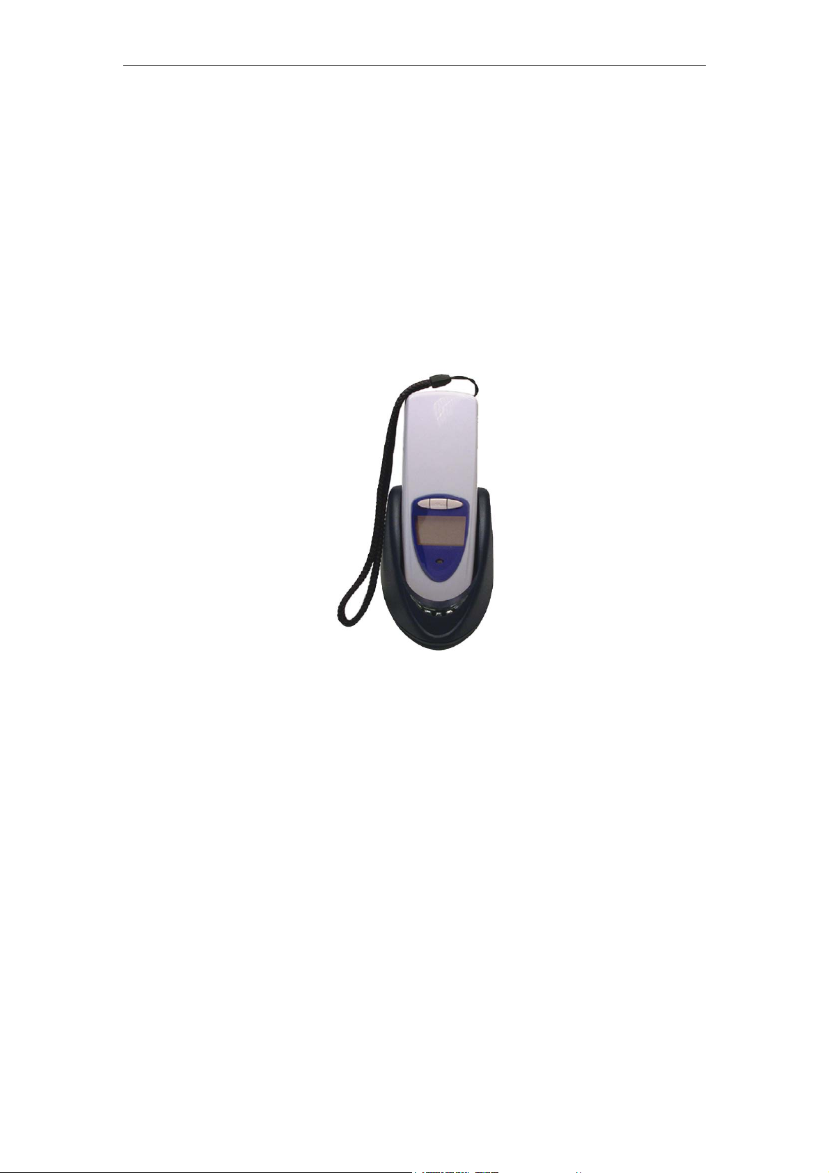
1. Keys
The OPL9724 has 3 control keys. In this small manual we use the names
button 1, button 2, and trigger key.
1 = button 1
¤ = trigger key
2 = button 2
Use button 1 and button 2 to navigate through the menu or to toggle between
options.
Use the trigger button to select the menu item.
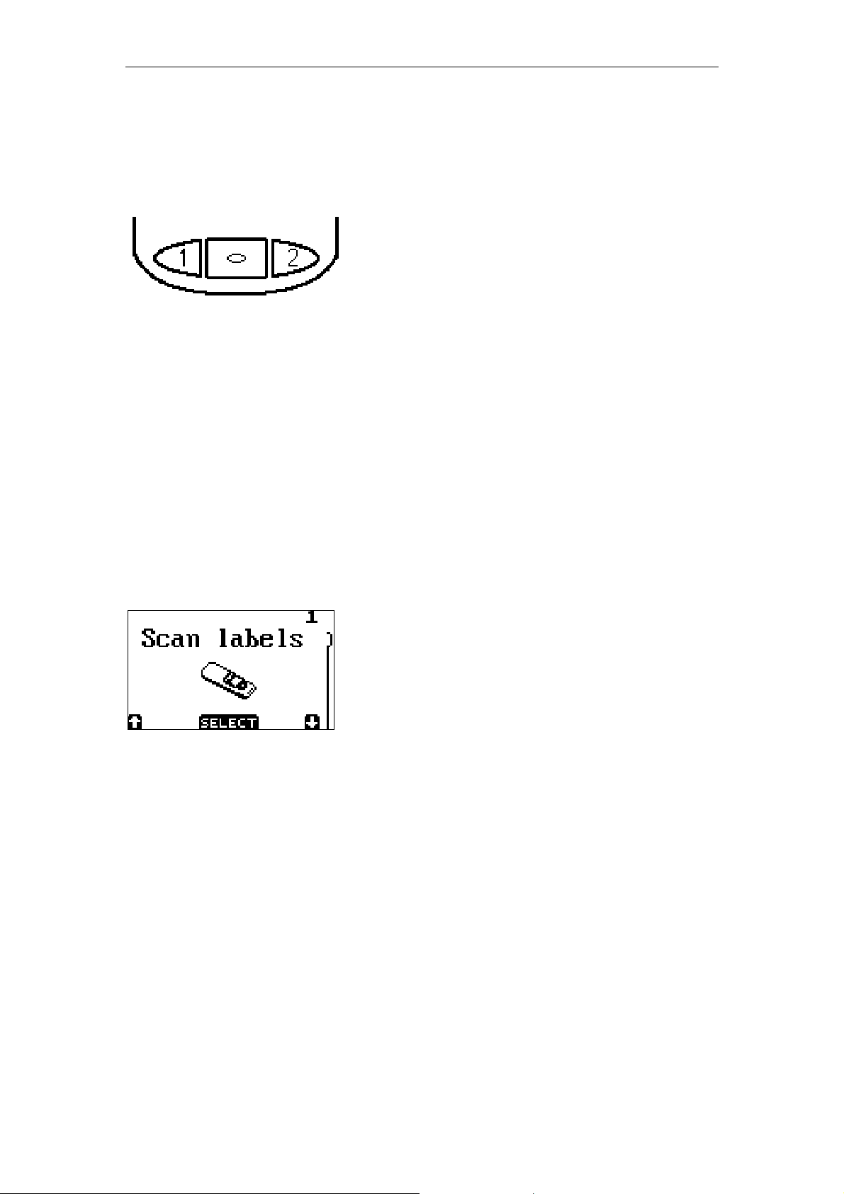
2. Main Menu
The main menu starts with the option Scan labels. Other options can be
selected by button 1 and 2.
Options of the main menu are:
• Scan labels
• Scroll data
• System menu
• Delete data
• Send data
• Version
Page 5
GRAPHICAL DEMO APPLICATION - PAGE 5
2.1 Scan Labels
No data on RAM disk.
By pressing the trigger button the laser line
emits and it is possible to scan a barcode.
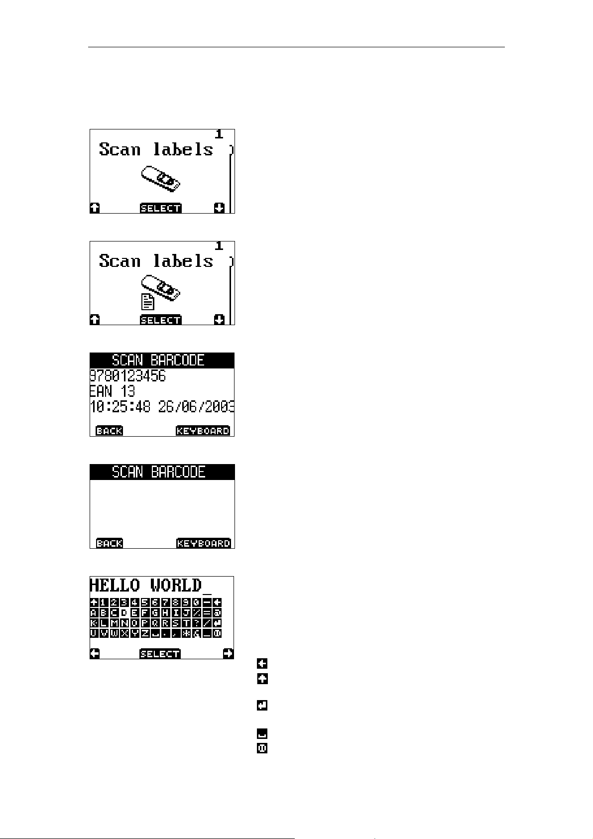
Data present on RAM disk.
By pressing the trigger button the laser line
emits and it is possible to scan more
barcodes.
Data in display after scanning a barcode.
Use button 1 (back) to return.
Use button 2 (keyboard) to start the special
full ASCII keyboard input.
Data that can not be scanned. Use the option
keyboard for manual input.
Use button 1 (back) to return.
Use button 2 (keyboard) to start the special
full ASCII keyboard input.
Data input with ASCII keyboard.
Use button 1 and button 2 to navigate through
the keyboard. The trigger button selects the
key that is highlighted white. The 4 key
symbols at the right means:
backspace key
upper case key, changes to lower case key
when selected and vice versa
enter key, to enter input and return to
barcode input screen.
space key
escape (exit) key to cancel input and return
to barcode input screen
Page 6
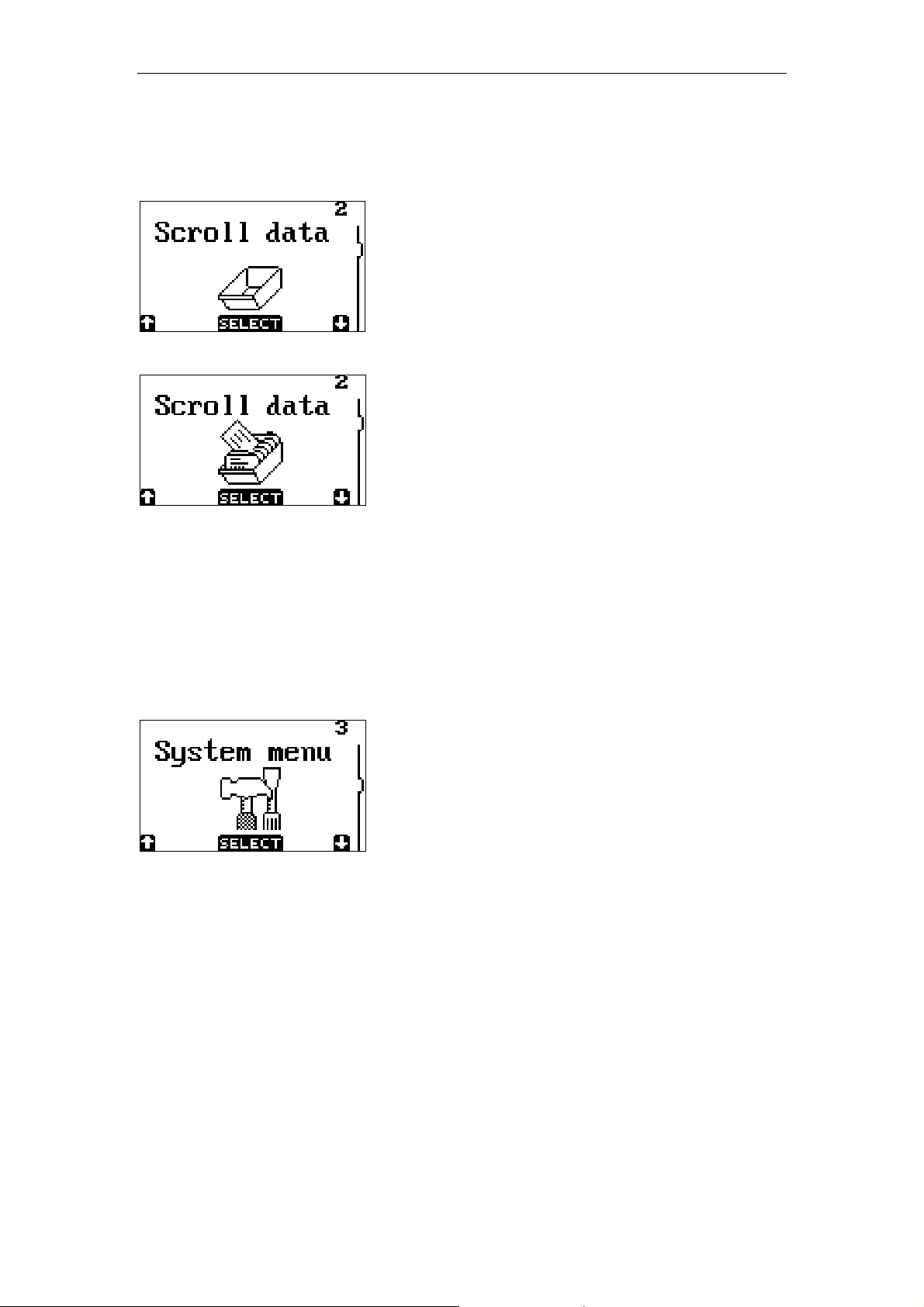
2.2 Scroll data
GRAPHICAL DEMO APPLICATION - PAGE 6
When no data is available the option select
will result in a message that there is no data
on the RAM disk.
When selecting this menu item it is possible to
scroll through the inputted data.
2.3 System menu
The System menu contains a submenu where special terminal options can be
viewed or set. The navigation of this menu is the same as navigating the main
menu.
The system menu consist of 7 items:
• (back)
• Barcodes
• Communicate
• Battery volt
• Memory
• Date / time
• Standby time
Page 7
GRAPHICAL DEMO APPLICATION - PAGE 7
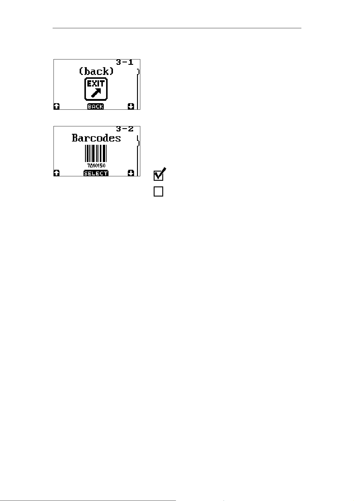
When the (back) menu item is selected the
application returns to the main menu.
The barcode menu enables or disables
barcode types that are supported by the
OPL9724. More barcodes can be enabled at
the same time.
Checked = enabling barcode
Unchecked = disabling barcode
Supported barcode types are:
• Code 39
• EAN
• UPC
• Interleaved 2 of 5
• Industrial 2 of 5
• Codabar
• Code 93
• Code 128
• MSI plessey
• Telepen
• UK plessey
• IATA
• Scode
• Matrix 2of5
• All Addons
By enabling all addons the addons for all
supported barcode types are enabled.
Page 8
GRAPHICAL DEMO APPLICATION - PAGE 8
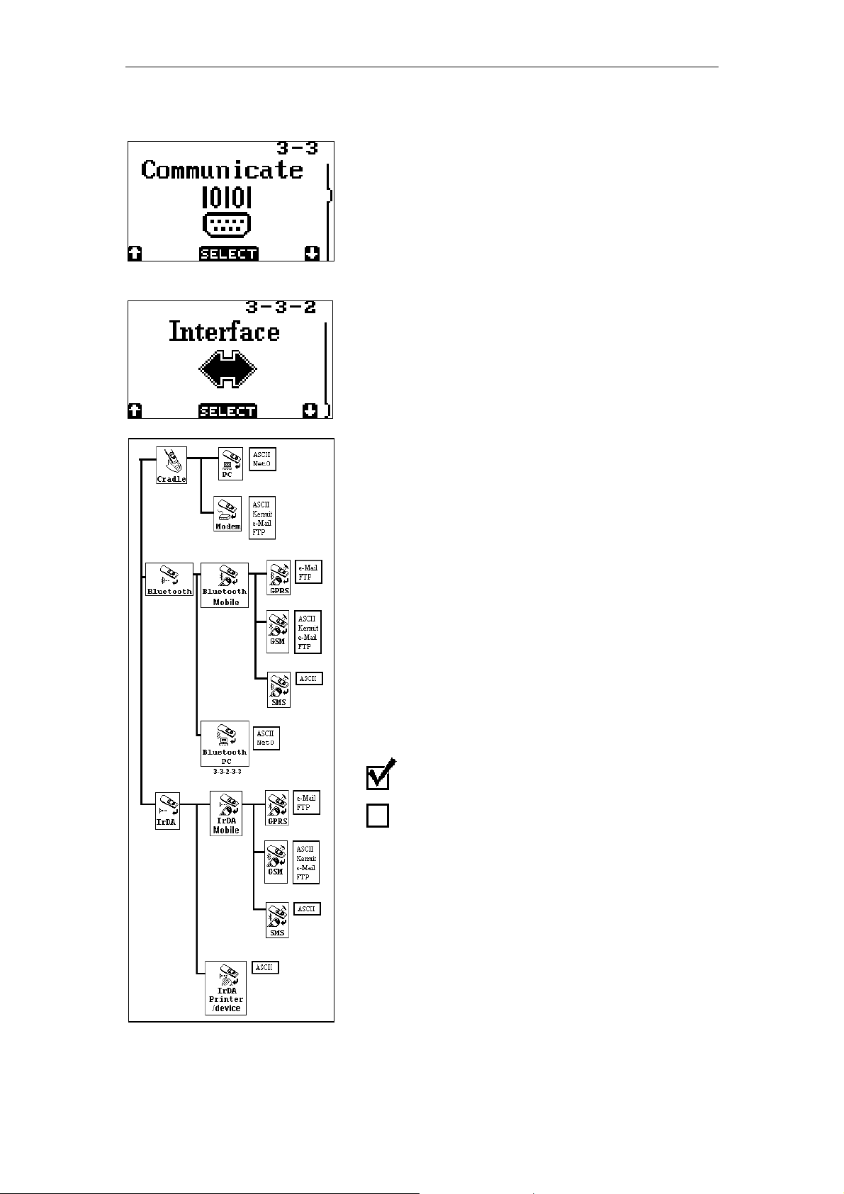
With the ‘Communicate’-menu the baudrate
and protocol as well as the setup for making a
dial-up connection with a remote ISP, a Mailserver and an FTP server can be set.
The Interface menu is a multiple layer menu in
which the communication method to send
data can be selected.
In total there are 23 communication methods
available in this demo application, which
makes it possible to send data to:
• Local PC’s using the cradle or bluetooth
• Remote PC’s using a mobile phone or
modem
• IrDA printers using IrDA
• Mobile phones by sending SMS messages
• Mail servers using a mobile phone or
modem
• FTP servers using a mobile phone or
modem
Every type of interface is linked to its own
protocol menu, which shows all the available
data protocols that are available for this
interface. When a certain protocol is selected
by pressing the Trigger key, the
demonstration program will sound a beep and
returns back to the start of the interface menu.
Checked = protocol is enabled
Unchecked = protocol is disabled
By selecting a new communication method
the previous selected method is disabled.
A more detailed description of this layered
Interface menu can be found in Appendix A.
Page 9
GRAPHICAL DEMO APPLICATION - PAGE 9
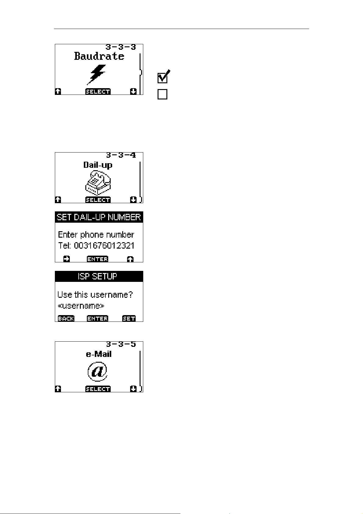
The baudrate menu enables or disables one
baudrate.
Checked = baudrate enabled
Unchecked = baudrate disabled
By selecting a new baudrate the previous
baudrate is disabled.
The Dial-up menu can be used to configure
the ISP settings for all the communication
methods that dial-in on an ISP server using a
modem or mobile phone.
These methods are:
• Cradle <Modem> Email
• Cradle <Modem> FTP
• Bluetooth Mobile phone <GSM> Email
• Bluetooth Mobile phone <GSM> FTP
• IrDA Mobile phone <GSM> Email
• IrDA Mobile phone <GSM> FTP
Using the 3 buttons of the OPL9724 the
following settings can be configured
• Telephone number of the ISP server
• Username/password combination of the
used Internet account at this server.
The email menu can be used to configure the
email settings for all the communication
methods that send an email to an SMTP
server
These methods are:
• Cradle <Modem> Email
• Bluetooth Mobile phone <GSM> Email
• Bluetooth Mobile phone <GPRS> Email
• IrDA Mobile phone <GSM> Email
• Bluetooth Mobile phone <GPRS> Email
Using the 3 buttons of the OPL9724 the
following settings can be configured:
• Senders email address
Email address that is being used as senders
Page 10

GRAPHICAL DEMO APPLICATION - PAGE 10
email address (this address which will appear
in the ‘From: ‘ line of the email). The email
address needs to correspond with the entered
user/name and password of the email
account.
• Recipients email address
This is the email address to which the email
will be send. (Address which will appear in the
‘From: ‘ line of the email
• IP-address of the SMTP-server
The IP-address of the SMTP server of the
used email account needs to be entered. This
server is used to send the email to.
• IP-address of the POP-server
The IP-address of the POP server of the used
email account needs to be entered. This
server is used for authentication purposes.
• Username/password of the email account
The username/password needs to correspond
with the senders email address
The FTP menu can be used to configure the
email settings for all the communication
methods that send the data file to an FTP
server
These methods are:
• Cradle <Modem> FTP
• Bluetooth Mobile phone <GSM> FTP
• Bluetooth Mobile phone <GPRS> FTP
• IrDA Mobile phone <GSM> FTP
• Bluetooth Mobile phone <GPRS> FTP
Using the 3 buttons of the OPL9724 the
following settings can be configured:
• IP-address of the FTP-server to which the
data file is send.
• Username/password of the FTP-server
The username/password needs to correspond
with the account of the used FTP-server
The battery voltage menu shows the current
input voltage of the battery.
Page 11

GRAPHICAL DEMO APPLICATION - PAGE 11
The memory menu shows the amount of free
memory on the RAM disk.
When the message that the RAM disk is
(almost) full appears then a small amount of
memory is still free. The still available free
memory is needed by data communication
from the Send data menu.
RAM disk is almost full, data is stored.
RAM disk is full, data is not stored.
The date / time menu item shows the current
day, date and time.
Use button 1 (BACK) to return to the system
menu.
Use button 2 (SET) to change the time and
date.
Use button 1 and 2 to navigate.
Use Trigger button to change the value where
the cursor is positioned.
When the cursor is placed under the E of End
the new time and date can be saved. If the
newly entered time or date is not a correct
value an error message is signaled.
Error in setting: Time or date
The new settings are not saved when the
error message is signaled.
Page 12

GRAPHICAL DEMO APPLICATION - PAGE 12
Selecting the standby time sets the time the
terminal stays on when no key is pressed.
When pressing one of the three keys will turn
the terminal back on.
Page 13

2.4 Delete data
GRAPHICAL DEMO APPLICATION - PAGE 13
When no data is available the option select
will result in a message that there is no data
on the RAM disk.
When selecting this menu item it is possible to
delete the inputted data.
The default screen when delete data is
selected and data is available. This screen will
also appear when a successful send data
(data transmission) occurs.
When cancel is selected the database is not
removed from the RAM disk.
Use button 1 or 2 to switch between delete
and cancel. When the delete option is
selected the database is removed from the
RAM disk and the application returns to the
main menu.
Page 14

2.5 Send data
GRAPHICAL DEMO APPLICATION - PAGE 14
By selecting the ‘Send data’-menu the
database, if present, can be transmitted to the
device type, protocol and baudrate as set in
the communication menu.
The Send pictogram that is shown when this
menu is selected shows information about the
selected communication settings by using
different symbols for different settings of the
selected communication methods.
In the list following all the used symbols are
shown.
Bluetooth connection
IrDA connection
Connection with a PC
Connection with a mobile phone
Connection with IrDA printer/device
Connection using the cradle and a PC
Connection with a serial modem
Connection using the GSM/GPRS network
Note:
When sending data to a PC using the cradle
the following communication parameters
should be used:
Parity = None
Databits = 8
Stopbits = 1
When selecting the Send data menu a
‘Transmit data’ message will appear on the
display that tells how the data will be send.
After pressing a key more specific message(s)
will appear which tell how to setup your
OPL9724 before starting the communication.
Page 15

GRAPHICAL DEMO APPLICATION - PAGE 15
These messages can be:
• Place the terminal in the cradle
• Place the terminal near the telephone
• Place the terminal near the PC
• Place terminal in front of IrDA port
• Ready to start sending, press a key
Besides these setup messages it is also
possible that a message will appear which
tells you to enter a specific setting before the
communication can start, like entering a
telephone number, a IP-address or an email
address. How these settings should be
entered can be read in the section about the
Communication menu.
More information about setting up a
connection can be read in Appendix A
After a successful transmission a message
appears to delete the database. See delete
data for more information.
Page 16

2.6 Version
GRAPHICAL DEMO APPLICATION - PAGE 16
Selection the version menu item the current
software version is shown.
The software version of this application.
Page 17

GRAPHICAL DEMO APPLICATION - PAGE 17
3. Data format
Each record is stored in a database file called DATA.TXT.
The fields in a record are:
<Barcode 50 characters right padded with spaces>
<Code ID 18 characters right padded with spaces>
<Time stamp 8 characters format HH:MM:SS>
<Date stamp 10 characters format DD/MM/YYYY>
A comma separates the fields in record and all records end with a <CR><LF>
character.
A Complete record looks like this:
<Barcode>,<Code ID>,<Time>,<Date><CR><LF>
Page 18

GRAPHICAL DEMO APPLICATION - PAGE 18
4. Battery
4.1. Battery charging
If the OPL9724 with the battery pack is placed
in the cradle, the voltage and the required
loading time is automatically determined.
During charging the OPL9724 shows one of
the images on the left. Also the RED led on
the terminal will emit.
When the battery is fully charged the led will
be GREEN and the image on the left will be
shown. The voltage meter shows the voltage
on the contacts of the battery.
Note
• When sending data (transmission) battery will also be charged. The led will emit RED or
GREEN, but the charging image is not displayed.
Page 19

GRAPHICAL DEMO APPLICATION - PAGE 19
4.2. Battery near empty
During operation a small amount of power is
drained from the battery. When the battery
detects that the battery is nearly empty, the
near empty message is alerted.
The OPL9724 can be placed on the cradle to
recharge the battery pack or press a key to
continue operation.
4.3. Battery empty
When already the battery near empty
message has been alerted and operation was
continued the battery empty message could
be alerted. This message indicates that the
battery needs to be recharged, it is not
possible to continue operation without
recharging the battery.
When the OPL9724 has been placed in the
cradle the battery-charging image appears. In
case the OPL9724 is picked from the cradle
and the battery is not enough charged than
the battery-empty message is shown again.
Place the OPL9724 in the cradle to charge the
battery further.
If the battery is enough charged after a battery
empty message. The application will start from
the scan labels in the main menu.
Page 20

GRAPHICAL DEMO APPLICATION - PAGE 20
Appendix A The interface Menu
In this appendix all the communication methods that can be selected in the
interface menu will be described. In the image below all the layers of this
menu are displayed with their corresponding menu codes (i.e. 3-3-2-2).
On the following pages these menu codes will be used as reference in the
descriptions about the communication methods.
The interface menu
Page 21

GRAPHICAL DEMO APPLICATION - PAGE 21
3-3-2-2 Making a serial connection with the CRD9723 cradle
Before trying to make a connection with the CRD9723 cradle its necessary to check
the DIP-switch settings of the cradle to verify if the baudrate settings of the cradle
match the selected baudrate in the demonstration program.
3-3-2-2-2 Making a serial connection with a PC
Connect the Cradle too the PC by connecting it’s standard serial cable to the serial
COM port of the PC.
When sending data to a PC using the cradle the following communication parameters
should be used:
Parity = None
Databits = 8
Stopbits = 1
3-3-2-2-2-2 Sending plain ASCII data to a PC
Run a serial communication program, like HyperTerminal. Always use the same
baudrate settings as the cradle and OPL9724 to be able to receive data from the
cradle. The data will be send as plain ASCII data to the PC
3-3-2-2-2-3 Sending the data file with the NetO protocol to a PC
Run the NetO file transfer program: download.exe to be able to receive the data file
using the NetO protocol. Make sure the correct baudrate and COM port are selected
in this program by using the command:
‘download.exe –p<COM port number> -b<baudrate setting>
i.e. download.exe –p1 –b115200
3-3-2-2-3 Making a serial connection with a modem
Before starting to connect the modem to your cradle please observe the following:
Due to the use of infrared communication between the cradle and the OPL9723
terminal, only half-duplex operation is permitted. Some modems implement command
echo in such a way that a command is echoed back before it is completely received.
If this is the case the modem must be configured in the application so that it doesn’t
echo commands.
That can be done connecting the modem to your PC and run a communication
program, like Windows HyperTerminal.
By sending the following commands the echo mode should be turned off and the
RTS/CTS should be set to their correct settings.
ATZ<enter> Resets modem
ATE0<enter> Turns off the echo mode
ATR1<enter> Sets CTS, ignore RTS
AT&W<enter> Stores new settings in memory
All AT-commands should return OK.
Page 22

GRAPHICAL DEMO APPLICATION - PAGE 22
When the modem does not respond to the AT commands, this line can be added to
the commands above:
AT&D0<enter> Modem doesn’t respond to the DTR signal
The cradles of the OPL9723 (cradle type CRD-9723) do not support hardware
handshaking. Configure the modem so that it doesn’t use hardware handshaking.
The standard 8P8 connector of the serial cable of the CRD9723 cradle is wired as a
DCE (Data Communication Equipment). The RS232 connector on standard modems
is also wired as a DCE (Data Communication Equipment) device. This will result in a
DCE-DCE connection, which means you‘ll have to use a “null modem” cable or
adapter.
If the modem has a 9-pin female (9F) RS232 connector a gender changer adapter
must be used to be able to connect the cable of the cradle to the modem.
If the modem has only a 25F connector, you should use a 9F to 25M adapter instead.
3-3-2-2-3-2 Sending plain ASCII data to a remote PC with a modem
The software calls a telephone number of a remote PC with a modem.
The remote modem should be initialized with ‘ATS0=1’-modem command so that the
modem will automatically go off hook and connects when being called.
Use a serial communication program like HyperTerminal or Procomm Plus to be able
to initialize the modem and view the received plain ASCII data.
3-3-2-2-3-3 Sending the data file to a remote PC with a modem using the
Kermit protocol.
The software calls the telephone number of a remote PC with a modem.
The remote PC should be running the program Procomm Plus (Windows or MS-DOS
version) in so-called host-mode.
The telephone number of the remote PC, the user name and password and the
version of Procomm Plus need to be specified before sending.
After running the log-in script of Procomm Plus, the Kermit protocol is used to send
the data file.
Important notes:
• The user name needs to contain both a first name and a last name separated by
a space (i.e. “JOHN DOE”).
• The entered user name/password-combination must also be set in Procomm Plus
otherwise the authorization fails.
• Procomm Plus for Windows will produce a ‘filename collision’-error if the data file:
‘DATA.TXT’ is already present in the download directory of Procomm. Therefor
the filename: ‘DATA.TXT’, must be deleted from the PC after each session.
3-3-2-2-3-4 Sending the data file the remote FTP server
The software calls a telephone number of a remote ISP server, using a password and
user name of an Internet account. After establishing a connection with the ISP server
the software will try to connect to a remote FTP server, by using its IP-address, a
username and a password. The data file will be placed in the root-directory of the
FTP-server.
Page 23

GRAPHICAL DEMO APPLICATION - PAGE 23
3-3-2-2-3-5 Email the data file the remote mail server using the SMTP
protocol
The software calls a telephone number of a remote ISP server, using a password and
user name of an Internet account. After establishing a connection with the ISP server
the software will try to connect to a remote SMTP server, by using its IP-address, the
senders-email address and the recipients emails address.
Before connecting to the SMTP server a connection with a POP-server is first made
to let the OPL9724 authenticate itself at the mail-server. To do this the IP-address of
the POP-server and a valid username and a password needs to be specified as well.
Page 24

GRAPHICAL DEMO APPLICATION - PAGE 24
3-3-2-3 Making a bluetooth connection
A connection between the OPL9724 and a bluetooth device, like mobile phones or PC's with
a bluetooth adapter, can be established by taken the following steps.
The first step of setting up a connection between the OPL9724 and the bluetooth device is by
making sure the bluetooth device is ‘discoverable’. Otherwise the OPL9724 can’t find the
bluetooth device.
The second step of setting up a bluetooth connection is to let the OPL9724 discover the other
device. This should done as follows:
• Go to the system menu of your OPL9724 by pressing all three buttons at the same time.
• Scroll down the system menu to the option: ‘Input address’ and select this option.
• In this menu, choose ‘Q2 discover’ (or choose Q1 to enter the address of the bluetooth
device manually)
• The OPL9724 will now start to search for bluetooth devices that are nearby, so make sure
the OPL9724 is near the bluetooth device. This process will take about half a minute
• After this process you will be asked to select one of the discovered bluetooth devices.
Choose your bluetooth device. (Which should be in the list, otherwise your bluetooth
device wasn’t activated or was incorrectly configured)
The next step of setting up a connection between the OPL9724 and a bluetooth device is
setting the bluetooth PIN-Code of your OPL9724. This should done as follows:
• Go to the system menu of your OPL9724 again
• Scroll down the system menu to the option: ‘Input PINcode’ and select this option.
• At this point you’ll be asked to enter the pin code. Using the navigation buttons to enter
the 4-digit pin code you would like to use. (i.e. 0000…….).
If you don’t wish to use a pin code, just clear the complete line with dots only.
• Press the trigger key to confirm the entered pin code.
The OPL9724 bluetooth module should now be ready to connect with your bluetooth device.
Page 25

GRAPHICAL DEMO APPLICATION - PAGE 25
3-3-2-3-2 Making a bluetooth connection with a mobile phone
To establish a bluetooth connection with a mobile phone, you’ll first need to set up your
mobile phone:
• Find the bluetooth option in the menu of your mobile phone
• Set the bluetooth option to: ON
Your mobile phone should now be ready to make a bluetooth connection
Before trying to connect to the mobile phone place the OPL9724 near your mobile phone
When establishing a bluetooth connection with a mobile phone, normally a message will
appear on your phone that you will have to enter a pin code to accept the connection between
the OPL9724. (Unless you have entered a empty pin code in the system menu)
Enter the same pin code as you entered in your OPL9724 in the system menu.
If your mobile then asks to accept the connection with the OPL9724 again, press ‘ACCEPT’.
After you’ve done this, it’s possible that the application has already returned with an error,
because it took too long to connect. This is normal. The second time you connect to the
mobile phone you don’t have to enter the pin code again and you only have to press
‘ACCEPT’ on your mobile phone if your mobile phone asks to accept the connection.
3-3-2-3-2-2 Sending data using the GPRS network of the mobile phone
Before you try to establish a bluetooth connection using the GPRS network make
sure your mobile phone has a working GPRS subscription.
The advantage of using the GPRS network is that you don’t have to enter a telephone
number, username and password of an ISP server. Besides this, establishing a
GPRS connection will go much faster then establishing a connection with ISP server
using the GSM network.
3-3-2-3-2-2-2 Sending the data file the remote FTP server using GPRS
After establishing the GPRS connection the software will try to connect to a remote
FTP server, by using its IP-address, a username and a password. The data file will be
placed in the root-directory of the FTP-server.
3-3-2-3-2-2-3Email the data the remote SMTP server using GPRS
After establishing the GPRS the software will try to connect to a remote SMTP server,
by using its IP-address, the senders-email address and the recipients emails address.
Before connecting to the SMTP server a connection with a POP-server is first made
to let the OPL9724 authenticate itself at the mail-server. To do this the IP-address of
the POP-server and a valid username and password needs to be specified as well.
3-3-2-3-2-3 Sending data using the GSM network of a mobile phone
Sending data using the GSM network of a mobile can be compared with sending data
using a wireless modem. This has the advantage that is possible to dial-in to a remote
modem or server at almost any location. The disadvantage of using a mobile GSM
connection is that it’s usually much slower then a serial modem (normally 9600bps)
Page 26

GRAPHICAL DEMO APPLICATION - PAGE 26
3-3-2-3-2-3-2Sending plain ASCII data to a PC using GSM
Before connecting, the remote modem should first be initialized with ‘ATS0=1’modem command so that the modem will automatically go off hook and connects
when being called.
A serial communication program, like HyperTerminal or Procomm Plus, should be
used to be able to initialize the modem and view the received plain ASCII data.
After setting up the bluetooth connection the software calls a telephone number of the
remote PC with a modem using the GSM network of the mobile phone. As soon as
the connection with the remote modem is established the data will be send a plain
ASCII data.
3-3-2-3-2-3-3 Sending the data file to a remote PC with a modem using the
Kermit protocol.
The software calls the telephone number of a remote PC with a modem.
The remote PC should be running the program Procomm Plus (Windows or MS-DOS
version) in so-called host-mode.
The telephone number of the remote PC, the user name and password and the
version of Procomm Plus need to be specified before sending.
After running the log-in script of Procomm Plus, the Kermit protocol is used to send
the data file.
Important notes:
• The user name needs to contain both a first name and a last name separated by
a space (i.e. “JOHN DOE”).
• The entered user name/password-combination must also be set in Procomm Plus
otherwise the authorization fails.
• Procomm Plus for Windows will produce a ‘filename collision’-error if the data file:
‘DATA.TXT’ is already present in the download directory of Procomm. Therefor
the filename: ‘DATA.TXT’, must be deleted from the PC after each session.
3-3-2-3-2-3-4Sending the data file the remote FTP server using GSM
After setting up the bluetooth connection the software calls a telephone number of the
remote ISP server, using a password and user name of an Internet account. After
establishing a connection with the ISP server the software will try to connect to the
remote FTP server, using its IP-address and a valid username and password.
The data file will be placed in the root-directory of the FTP-server.
3-3-2-3-2-3-5Email the data the remote SMTP server using GSM
After setting up the bluetooth connection the software calls a telephone number of a
remote ISP server, using a password and user name of an Internet account. After
establishing a connection with the ISP server the software will try to connect to a
remote SMTP server, by using its IP-address, the senders-email address and the
recipients emails address.
Before connecting to the SMTP server a connection with a POP-server is first made
to let the OPL9724 authenticate itself at the mail-server. To do this the IP-address of
the POP-server and a valid username and a password needs to be specified as well.
3-3-2-3-2-4 Sending data to a remote mobile phone using SMS
After setting up the bluetooth connection the mobile phone is used to send the data of
a single bar code to a remote mobile phone using the SMS protocol. The telephone
number of the remote telephone needs to be specified first.
Page 27

GRAPHICAL DEMO APPLICATION - PAGE 27
3-3-2-3-3 Making a bluetooth connection with a PC
To establish a bluetooth connection with a PC using a virtual bluetooth COM port,
you’ll need to set up your PC as follows:
• Connect the bluetooth adapter to your PC
• Make sure your PC has detected the bluetooth adapter and has installed the correct
software, which should have created one or more virtual serial COM ports (i.e.
COM4)
Before connecting make sure you’ve let the OPL9724 successfully discover your PC
(See 3-3-2-3, making a bluetooth connection)
Your PC should then be ready to receive data from your OPL9724.
3-3-2-3-3-2 Sending plain ASCII data to a PC with bluetooth
Run a serial communication program, like HyperTerminal. Open the virtual bluetooth
COM port when being asked to select a COM port for a new connection. After that,
set the COM port back to its default values (choosing a specific baudrate isn’t
necessary).
After establishing the bluetooth connection, the data will be send as plain ASCII data
to the PC.
3-3-2-3-3-3 Sending the data file with the NetO protocol to a PC
Run the NetO file transfer program, like download.exe to be able to receive the data
file using the NetO protocol. Make sure the correct baudrate and COM port are
selected in this program.
Note:
The MS-DOS version of the program download.exe can’t open a virtual bluetooth
COM port.
Page 28

GRAPHICAL DEMO APPLICATION - PAGE 28
3-3-2-4 Making an IrDA (infrared) connection
Before it is possible to make an IrDA connection make sure the IrDA port of the IrDA
device is turned on.
Before trying to make an IrDA connection always make sure the IrDA port of the
OPL9724 is in line of sight of the IrDA port of the IrDA device.
3-3-2-4-2 Making an IrDA connection with a mobile phone
To turn on the IrDA port of a mobile phone search for the IrDA option in the menu
structure of your mobile phone, then activate the IrDA port of your mobile phone.
3-3-2-4-2-2 Sending data using the GPRS network of the mobile phone
Before you try to establish a bluetooth connection using the GPRS network make
sure your mobile phone has a working GPRS subscription.
The advantage of using the GPRS network is that you don’t have to enter a telephone
number, username and password of an ISP server. Besides this, establishing a
GPRS connection will go much faster then establishing a connection with ISP server
using the GSM network.
3-3-2-4-2-2-2Sending the data file the remote FTP server using GPRS
After establishing the GPRS connection the software will try to connect to a remote
FTP server, by using its IP-address, a username and a password. The data file will be
placed in the root-directory of the FTP-server.
3-3-2-4-2-2-3Email the data the remote SMTP server using GPRS
After establishing the GPRS the software will try to connect to a remote SMTP server,
by using its IP-address, the senders-email address and the recipients emails address.
Before connecting to the SMTP server a connection with a POP-server is first made
to let the OPL9724 authenticate itself at the mail-server. To do this the IP-address of
the POP-server and a valid username and password needs to be specified as well.
3-3-2-4-2-3 Sending data using the GSM network of the mobile phone
Sending data using the GSM network of a mobile can be compared with sending data
using a wireless modem. This has the advantage that is possible to dial-in to a remote
modem or server at almost any location. The disadvantage of using a mobile GSM
connection is that it’s usually much slower then a serial modem (normally 9600bps)
3-3-2-4-2-3-2Sending plain ASCII data to a PC using GSM
Before connecting, the remote modem should first be initialized with ‘ATS0=1’modem command so that the modem will automatically go off hook and connects
when being called.
A serial communication program, like HyperTerminal or Procomm Plus, should be
used to be able to initialize the modem and view the received plain ASCII data.
After setting up the IrDA connection the software calls a telephone number of the
remote PC with a modem using the GSM network of the mobile phone. As soon as
the connection with the remote modem is established the data will be send a plain
ASCII data.
3-3-2-3-2-3-4 Sending the data file to a remote PC with a modem using the
Kermit protocol.
Page 29

GRAPHICAL DEMO APPLICATION - PAGE 29
The software calls the telephone number of a remote PC with a modem.
The remote PC should be running the program Procomm Plus (Windows or MS-DOS
version) in so-called host-mode.
The telephone number of the remote PC, the user name and password and the
version of Procomm Plus need to be specified before sending.
After running the log-in script of Procomm Plus, the Kermit protocol is used to send
the data file.
Important notes:
• The user name needs to contain both a first name and a last name separated by
a space (i.e. “JOHN DOE”).
• The entered user name/password-combination must also be set in Procomm Plus
otherwise the authorization fails.
• Procomm Plus for Windows will produce a ‘filename collision’-error if the data file:
‘DATA.TXT’ is already present in the download directory of Procomm. Therefor
the filename: ‘DATA.TXT’, must be deleted from the PC after each session.
3-3-2-4-2-3-4Sending the data file the remote FTP server using GSM
After setting up the IrDA connection the software calls a telephone number of the
remote ISP server, using a password and user name of an Internet account. After
establishing a connection with the ISP server the software will try to connect to the
remote FTP server, using its IP-address and a valid username and password.
The data file will be placed in the root-directory of the FTP-server.
3-3-2-4-2-3-5Email the data the remote SMTP server using GSM
After setting up the IrDA connection the software calls a telephone number of a
remote ISP server, using a password and user name of an Internet account. After
establishing a connection with the ISP server the software will try to connect to a
remote SMTP server, by using its IP-address, the senders-email address and the
recipients emails address.
Before connecting to the SMTP server a connection with a POP-server is first made
to let the OPL9724 authenticate itself at the mail-server. To do this the IP-address of
the POP-server and a valid username and a password needs to be specified as well.
3-3-2-4-2-4 Sending data to a remote mobile phone using SMS
After setting up the IrDA connection the mobile phone is used to send the data of a
single bar code to a remote mobile phone using the SMS protocol. The telephone
number of the remote telephone needs to be specified first.
3-3-2-4-3 Making an IrDA connection with an IrDA printer/device
Before making the connection make sure the IrDA port of the IrDA device is turned
on, so the device can connect to your OPL9724
3-3-2-4-2-3-2 Sending plain ASCII data to an IrDA printer/device
Place the IrDA port of the OPL9724 in line op site of the IrDA printer/device
 Loading...