

Page 1
CAUTION: This information is subject to
change without prior notice.
Copyright 2006, Opticon Sensors Europe
B.V. All rights reserved.
This manual may not, in whole or in part, be
copied, photocopied, reproduced, translated or
converted to any electronic or machine
readable form without prior written consent of
Opticon Sensors Europe.
THE GENERAL USE AND FUNCTIONING OF
THE BAR CODE SCANNER IS DESCRIBED
IN THIS DOCUMENT. ALSO GENERAL
SETUP INSTRUCTIONS TO GET STARTED
ARE DESCRIBED IN THIS DOCUMENT. FOR
FURTHER INSTRUCTIONS CONSULT
OPTICON OR YOUR LOCAL DEALER.
BRIEF SETUP
WIRELESS READER
CONFIGURATION
INSTRUCTIONS
The reader is configured to default factory settings
and is supplied with information that gives you a
quick understanding of the product. More product
details, additional support, or configuration options
to your own preferences (by Universal menu book)
will be updated at www.opticon.com
To enable the reader to communicate to another
device, different steps can be taken, depending on
the situation.
Overview of situations
• The address of the device must be configured in
the reader. Possibly the address of the device
needs to be retrieved first.
• To connect an Opticon reader to a third party
dongle, the reader must be configured.
• In case a third party dongle is used, the address
and pin code need to be configured manually.
Consult your dongle’s manual how to obtain the
address and configure the pin code. You need
this information to configure the bar code reader.
The dongle's driver installs a serial port on the
computer, which is used by the bar code reader
to transmit the data.
• The reader can connect by scanning the other
device’s address label or by making the reader
discoverable to the other device.
• To stop the connection manually use the special
disconnection label.
The necessary steps and instructions are
explained on the next pages:
printed June, 2006
OPTICON - 1
Page 2

Overview of steps
Depending on the type of device to be connected,
take the steps as further described. To configure
the required options:
• scan the SET label
• scan the required option(s)
• scan the END label
After scanning the END label, the new settings are
stored in non volatile memory.
Reader to Cradle
• connect by scanning (step 3 A )
PC to reader
• discover & connect (step 3 B)
Reader to PC / Other device
• retrieve device address (step 1)
• connect mode (step 2)
• security options (step 2 Optional)
• connect by scanning (step 3 A)
To disconnect the current reader:
• scan the disconnect label (step disconnect)
---------------------------------------------------------------
[STEP 1]
– RETRIEVE ADDRESS
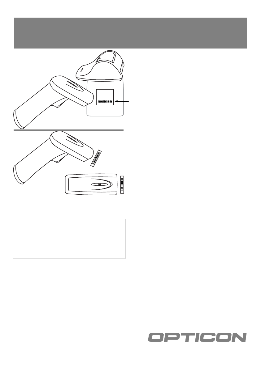
The address is mostly displayed on the product
label as a hexadecimal code (example: 00-11-F603-39-69). Otherwise consult the documentation of
the device how to retrieve the device address code.
To enable the reader to communicate to the other
device, the reader must be configured with this
code. The easiest way to do this is to create a
barcode label of the hexadecimal code as
described below.
– CREATE LABEL
Opticon provides a simple on-line application on
http://opticonfigure.opticon.com/bluetooth.asp
http://opticonfigure.opticon.com/ieee.asp
• Type in the digits of the hexadecimal code in
numbers and capital characters without dashes,
dots and spaces (example: 0011F6033969).
• Submit the code into a barcode (example:
0011F6033969). You hav e to print the screen
to have it available for scanning.
or
To return to default settings:
• scan the reset label (step reset)
2 - OPTICON
---------------------------------------------------------------
[STEP 2]
CONNECT MODE
SET
Connect to
PC
END
---------------------------------------------------------------
_ZZ_
_CNPC_
_ZZ_
ZZ
CNPC
ZZ
Page 3

[STEP 2 OPTIONAL]
SECURITY OPTIONS
The third party dongle usually allows
authentication, which means a PIN-code can be
used to establish a secure connection. Note that
the PIN-code is case sensitive, e.g. there is a
difference between lower case und upper case
(example: difference between ‘a’ and ‘A’).
Set PIN-code table
0
1
2
3
_Q0_
_Q1_
_Q2_
_Q3_
Q0
Q1
Q2
Q3
SET
Set PIN-code
label
Scan PINcode input
End PIN-code
label
END
a
b
c
_ZZ_
_PINS_
see input tables
_PINE_
_ZZ_
_$A_
_$B_
_$C_
$A
$B
$C
ZZ
PINS
PINE
ZZ
4
5
6
7
8
9
A
B
C
_Q4_
_Q5_
_Q6_
_Q7_
_Q8_
_Q9_
_0A_
_0B_
_0C_
Q4
Q5
Q6
Q7
Q8
Q9
0A
0B
0C
d
e
f
_$D_
_$E_
_$F_
$D
$E
$F
D
E
F
_0D_
_0E_
_0F_
0D
0E
0F
OPTICON - 3
Page 4

---------------------------------------------------------------
[STEP 3 A]
CONNECT BY SCANNING
---------------------------------------------------------------
[STEP DISCONNECT]
(SET + END label not required):
– CRADLE
• Scan the device address barcode on the bottom
of the cradle.
– OTHER DEVICE
• Scan the address barcode that you just created in
the on-line Opticon application (step 1).
---------------------------------------------------------------
[STEP 3 B]
DISCOVER
Set the reader in discoverable and connectable
mode:
• If an Opticon cradle is supplied: Place the reader
in the cradle. The reader is discoverable while it
is in the cradle.
• If no cradle is supplied: Scan the label to make
the reader discoverable for 3 minutes.
(SET + END label not required):
Make discoverable & connectable
_+-DSCO-+_
Set the PC / Other device to discover the reader:
• The name of the reader will be displayed as
Productname-xxxx. Example (OPL2724-3969)
+-DSCO-+
Manually disconnect
_+-DISC-+_
---------------------------------------------------------------
+-DISC-+
[STEP RESET]
SET
Reset
END
---------------------------------------------------------------
_ZZ_
_SO_
_ZZ_
ZZ
SO
ZZ
CONNECT
Connect the PC / Other device to the reader:
• Follow the instructions of the device.
• The application might ask for a PIN-code. In this
case the 4 last reader name characters are
entered into the application.
(Example: reader name is OPL2724-3969,
required application PIN-code is 3969)
---------------------------------------------------------------
4 - OPTICON
 Loading...