

Page 1

NLV-5201
Fixed Position 2D Imager Scanner
User's Manual
Page 2

The information in this document is subject to change without notice.
Document History
Model Number: NLV-5201 Specification Number: TS18047
Edition: 1st Original Spec Number: (TS18046)
Date: 22-February-2019
© 2019 Opticon. All rights reserved.
This manual may not, in whole or in part, be copied, photocopied, reproduced, translated or converted
to any electronic or machine readable form without prior written consent of Opticon.
Limited Warranty and Disclaimers
Please read this manual carefully before installing or using the product.
Serial Number
A serial number appears on all Opticon products. This official registration number is directly related to
the device purchased. Do not remove the serial number from your Opticon device. Removing the
serial number voids the warranty.
Warranty
Unless otherwise agreed in a written contract, all Opticon products are warranted against defects in
materials and workmanship for two years after purchase excluding batteries. Opticon will repair or, at
its option, replace products that are defective in materials or workmanship with proper use during the
warranty period. Opticon is not liable for damages caused by modifications made by a customer. In
such cases, standard repair charges will apply. If a product is returned under warranty and no defect is
found, standard repair charges will apply. Opticon assumes no liability for any direct, indirect,
consequential or incidental damages arising out of use or inability to use both the hardware and
software, even if Opticon has been informed about the possibility of such damages.
Packaging
The packing materials are recyclable. We recommend that you save all packing material to use should
you need to transport your data collector or send it for service. Damage caused by improper
packaging during shipment is not covered by the warranty.
Trademarks
Trademarks used are the property of their respective owners.
Opticon Inc. and Opticon Sensors Europe B.V. are wholly owned subsidiaries of
OPTOELECTRONICS CO.,LTD., 12-17, Tsukagoshi 4-chome, Warabi-shi, Saitama, Japan 335-0002.
TEL +81-(0) 48-446-1183; FAX +81-(0) 48-446-1184
SUPPORT
USA Europe
Phone: 800-636-0090 Phone: +31235692728
Email: support@opticonusa.com Email: support@opticon.com
Web: www.opticonusa.com Web: www.opticon.com
Page 3

NLV-5201
i
User's Manual 1st
Caution and Warning
Read following caution carefully before installing and/or using this product. Incorrect handling may
cause malfunction, overheating, smoke, fire, injury and electric shock etc.
Caution
Electrical handling
・In case any abnormality occurs in the scanner or stops working, unplug the cable and the AC
adapter and contact the dealer. Leaving as is may cause malfunction, overheating, smoke and fire.
・Do not use this product at voltage outside the specified range. It may cause overheating, smoke and
fire.
・Do not let the AC adapter get wet. It may cause overheating, smoke, fire and electric shock.
・Do not plug/unplug the connectors while power is supplied.
Excessive shock / stress
・Do not drop this product.
・Do not push or place this product under or between heavy items.
・Do not swing the product around by the cable. It may cause injury or damage to the device.
Cable handling
・Do not wrap NLV-5201 cable around a host device (PC, tablet etc.). It may cause breakage to the
strain relief and the cable jacket, and could cause malfunction, overheating, smoke and fire.
・Do not place this product and AC adapter under or between heavy items.
・Do not bend the cable at extremely low temperatures.
・Immediately unplug the cable and AC adapter, then contact your dealer if:
If the cable jacket tears open or separates from the connector.
If any core wire, become exposed.
If the cable generates heat, even if it looks normal.
Continued use in any of these conditions may cause malfunction, overheating, and/or fire.
Operating environment
・Do not use this product at temperatures outside the specified range.
・Do not use this product near combustible materials (gas, gunpowder etc.). It may cause smoke and
fire.
・Do not immerse this product in water or any other liquid.
・If any condensation forms on the product, abstain from the use of it until moisture has evaporated to
prevent malfunctions.
・Do not store this product in dusty environments and in extremely high humidity.
・Do not store this product in extremely cold or hot places.
・Avoid exposure to direct sunlight for long periods of time.
・Avoid static electricity and do not put the product near a radio or a TV. Excessive static electricity
may cause malfunction.
・Do not place in an unstable place.
Others
・Do not disassemble this product.
・Do not stare into the LED light from the scan window. It may damage your eyes.
・Do not soil or scratch the scan window. It may have a bad effect on the reading.
・Do not expose this product to edible / industrial fat and chemicals.
・This product may be affected by an instantaneous power-on condition of machinery, lighting, or
motors, etc.
・Do not let children use this product.
Page 4

NLV-5201 User's Manual
ii
1st
This device complies with part 15 of the FCC Rules. Operation is subject to the following two
conditions: ( 1 ) this device may not cause harmful Interference, and ( 2 ) this device must accept
any interference received, including interference that may cause undesired operation.
この装置は、クラスB機器です。この装置は、住宅環境で使用することを目的としています
が、この装置がラジオやテレビジョン受信機に近接して使用されると、受信障害を引き起こすこ
とがあります。
取扱説明書に従って正しい取り扱いをして下さい。 VCCI-B
Regulatory Compliance
(1) LED Safety
IEC 62471 Exempt Risk Group
(2) EMC
EN 55024, EN 55032 Class B
FCC Part 15 Subpart B Class B
VCCI クラス B
Disclaimer:
OPTOELECTRONICS CO.,LTD. Will not bear any responsibility in case of malfunction, accident,
repair and damage assurance.
Page 5

NLV-5201 User's Manual
iii
1st
Edition
Date
Page
Section
Description of Changes
Prelimina
ry
2019/02/22
-
-
Initial release
Revision History
Document Name : NLV-5201 User's Manual
Page 6

NLV-5201 User's Manual
iv
1st
Contents
Caution and Warning ............................................................................................................................. i
1 Abstract .......................................................................................................................................... 1
Features of the Scanner ........................................................................................................... 2 1.1
Usage of the Scanner ............................................................................................................... 3 1.2
Flow to Integrate ....................................................................................................................... 4 1.3
Flow to Integrate for Industrial Uses ................................................................................. 4 1.3.1
Flow to Integrate for General Uses ................................................................................... 5 1.3.2
2 Before Using .................................................................................................................................. 6
Model Details ............................................................................................................................ 7
2.1
Standard ........................................................................................................................... 7 2.1.1
Model Description ............................................................................................................. 7 2.1.2
Package Contents .................................................................................................................... 8 2.2
Connect to the Host .................................................................................................................. 9 2.3
How to Read ........................................................................................................................... 11 2.4
Depth of Field and Focus Type .............................................................................................. 12 2.5
Standard Model (SR) Depth of Field .............................................................................. 12 2.5.1
High Resolution Model (HD) Depth of Field ................................................................... 13 2.5.2
Ultra High Resolution model (UD) Depth of Field ........................................................... 14 2.5.3
Detailed View ......................................................................................................................... 15 2.6
Operation Mode and Control Panel Description .................................................................... 16 2.7
Operation Mode .............................................................................................................. 16 2.7.1
Control Panel Operation Specifications .......................................................................... 17 2.7.2
LED Indicator Specifications ........................................................................................... 18 2.7.3
Buzzer and LED Indicator ............................................................................................... 19 2.7.4
Operation Transition ............................................................................................................... 20 2.8
Normal Trigger ................................................................................................................ 20 2.8.1
Auto Trigger .................................................................................................................... 21 2.8.2
Operation Invalid Transition Diagram ............................................................................. 22 2.8.3
Installation of the Scanner ...................................................................................................... 23 2.9
Scan Area ............................................................................................................................... 24 2.10
Image Range .................................................................................................................. 24 2.10.1
Optical Path .................................................................................................................... 25 2.10.2
Scanned Media and Placement ............................................................................................. 26 2.11
Solution for Specular Reflection of the LED Illumination ................................................ 26 2.11.1
Solution for Specular Reflection of the External Illumination.......................................... 27 2.11.2
Exit Window Placement .......................................................................................................... 28 2.12
Exit Window Material ...................................................................................................... 28 2.12.1
Solution for Specular Reflection of the Illumination ........................................................ 29 2.12.2
3 Configurations ............................................................................................................................. 30
Configuring with Commands .................................................................................................. 31 3.1
Page 7

NLV-5201 User's Manual
v
1st
Command Packet ........................................................................................................... 31
3.1.1
Configuring with 2D Menu .............................................................................................. 32 3.1.2
Configuring with 1D Menu Code ..................................................................................... 33 3.1.3
Command Packet Sending Precautions ................................................................................ 34 3.2
Each interface Default Setting ........................................................................................ 34 3.2.1
Save Settings .................................................................................................................. 35 3.2.2
Custom Setting ............................................................................................................... 35 3.2.3
Basic Commands ................................................................................................................... 36 3.3
ACK/NAK for Serial Commands ..................................................................................... 36 3.3.1
Diagnostic Commands .................................................................................................... 36 3.3.2
Enable/Disable 2D Menu Code ...................................................................................... 36 3.3.3
Enable/Disable 1D Menu Code ...................................................................................... 36 3.3.4
Image Settings ................................................................................................................ 37 3.3.5
Disable Reading Operation ............................................................................................ 38 3.3.6
Buzzer and Indicator ....................................................................................................... 38 3.3.7
Reboot the Scanner ........................................................................................................ 38 3.3.8
Enable/Disable Mode Key .............................................................................................. 38 3.3.9
Direct Numerical Input Command .................................................................................. 39 3.3.10
4 Indicator Options ......................................................................................................................... 40
Buzzer .................................................................................................................................... 41 4.1
Buzzer Loudness ............................................................................................................ 41 4.1.1
Good Read Buzzer ......................................................................................................... 41 4.1.2
Start-up Buzzer ............................................................................................................... 42 4.1.3
Read Timeout Buzzer ..................................................................................................... 42 4.1.4
Intermediate Buzzer ........................................................................................................ 42 4.1.5
Status LED ............................................................................................................................. 43 4.2
Status LED Lighting Time ............................................................................................... 43 4.2.1
Good Read Aiming ................................................................................................................. 44 4.3
Indicator in General ................................................................................................................ 45 4.4
Indicator Timing .............................................................................................................. 45 4.4.1
5 Interface ........................................................................................................................................ 46
RS-232C ................................................................................................................................. 47 5.1
RS-232C Basic Information ............................................................................................ 48 5.1.1
Baud Rate (Transfer Speed) .......................................................................................... 48 5.1.2
Character Format ............................................................................................................ 49 5.1.3
Handshaking (Flow Control) ........................................................................................... 49 5.1.4
Inter Character Delay (RS-232C) ................................................................................... 54 5.1.5
Trouble Shooting (RS-232C) .......................................................................................... 54 5.1.6
USB-HID ................................................................................................................................. 55 5.2
USB-HID Basic Information ............................................................................................ 56 5.2.1
Connection Confirmation (USB-HID) .............................................................................. 57 5.2.2
NumLock CapsLock control ............................................................................................ 57
5.2.3
Page 8

NLV-5201 User's Manual
vi
1st
Data Output Speed (USB-HID) ....................................................................................... 58
5.2.4
Inter Character Delay (USB-HID) ................................................................................... 58 5.2.5
Keyboard Language ....................................................................................................... 59 5.2.6
Trouble Shooting (USB-HID) .......................................................................................... 60 5.2.7
USB-COM .............................................................................................................................. 61 5.3
USB-COM Basic Information .......................................................................................... 62 5.3.1
Integration (USB driver) .................................................................................................. 62 5.3.2
Connection Confirm ........................................................................................................ 62 5.3.3
Fixed USB-COM Port ..................................................................................................... 63 5.3.4
Connection Method ......................................................................................................... 63 5.3.5
COM to HID Output ........................................................................................................ 63 5.3.6
Trouble Shooting (USB-COM) ........................................................................................ 64 5.3.7
Common Settings ................................................................................................................... 65 5.4
Data Buffer Mode ............................................................................................................ 65 5.4.1
6 Reading and Timing .................................................................................................................... 66
Reading and Trigger Control .................................................................................................. 67 6.1
Code Read Timing .......................................................................................................... 67 6.1.1
Command Trigger Control .............................................................................................. 68 6.1.2
External Trigger Signal Control ...................................................................................... 69 6.1.3
Read Time Setting .......................................................................................................... 70 6.1.4
Trigger Delay .................................................................................................................. 71 6.1.5
Decode Timeout ............................................................................................................. 72 6.1.6
OK/NG Signal ......................................................................................................................... 73 6.2
Enable/Disable OK/NG signal ........................................................................................ 73 6.2.1
OK/NG Signal Behavior Settings .................................................................................... 74 6.2.2
7 Tuning and Bank Function ......................................................................................................... 75
Tuning Overview .................................................................................................................... 76 7.1
Tuning Function .............................................................................................................. 76 7.1.1
Tuning Setting Flow ........................................................................................................ 77 7.1.2
Tuning..................................................................................................................................... 78 7.2
Execute Tuning ............................................................................................................... 78 7.2.1
Setting the Exposure Adjustment Range of Tuning ....................................................... 79 7.2.2
Reading Test .......................................................................................................................... 80 7.3
Reading Test Command ................................................................................................. 80 7.3.1
Bank Function ........................................................................................................................ 81 7.4
Bank Selection ................................................................................................................ 81 7.4.1
Bank Specify Trigger ...................................................................................................... 81 7.4.2
Confirm Current Bank ..................................................................................................... 81 7.4.3
Initialize Bank .................................................................................................................. 81 7.4.4
8 Read Options ............................................................................................................................... 82
Read Modes Overview ........................................................................................................... 83 8.1
Read Operation Flow ...................................................................................................... 83
8.1.1
Page 9

NLV-5201 User's Manual
vii
1st
Read Modes ................................................................................................................... 84
8.1.2
Batch Reading ................................................................................................................ 86 8.1.3
Data Edit Function .......................................................................................................... 86 8.1.4
Auto Trigger ............................................................................................................................ 87 8.2
Normal Auto Trigger (Without Stand) ............................................................................. 87 8.2.1
Auto Trigger Sensitivity ................................................................................................... 87 8.2.2
Double Read Reset Time ............................................................................................... 87 8.2.3
Read Time Adjustment ................................................................................................... 88 8.2.4
Auto Trigger Sleep Mode ................................................................................................ 88 8.2.5
Illumination and Aiming .......................................................................................................... 89 8.3
Reading LED Illumination ............................................................................................... 89 8.3.1
LED Aiming ..................................................................................................................... 89 8.3.2
9 Code Options ............................................................................................................................... 90
Setting of Readable Codes .................................................................................................... 91 9.1
1D Codes ........................................................................................................................ 91 9.1.1
Postal Code .................................................................................................................... 92 9.1.2
GS1 DataBar .................................................................................................................. 93 9.1.3
GS1 Composite Code ..................................................................................................... 93 9.1.4
2D Codes ........................................................................................................................ 94 9.1.5
Other Options for Codes ................................................................................................. 94 9.1.6
OCR ................................................................................................................................ 95 9.1.7
Setting of Code Common Options ......................................................................................... 96 9.2
GS1 Convert ................................................................................................................... 96 9.2.1
Positive and Negative Image of Barcodes (1D code common) ...................................... 97 9.2.2
Redundancy (1D code common) .................................................................................... 98 9.2.3
Add-on waiting time ........................................................................................................ 98 9.2.4
ECI Protocol Output ........................................................................................................ 99 9.2.5
OCR Free Edit .............................................................................................................. 100 9.2.6
Setting of Code Specific Options ......................................................................................... 101 9.3
UPC .............................................................................................................................. 101 9.3.1
EAN/JAN ....................................................................................................................... 104 9.3.2
Code 39 and It. Pharm (Code 32) ................................................................................ 108 9.3.3
Codabar ........................................................................................................................ 110 9.3.4
Interleaved 2 of 5 and S-Code ...................................................................................... 112 9.3.5
Code128 ....................................................................................................................... 113 9.3.6
IATA .............................................................................................................................. 114 9.3.7
MSI/Plessey .................................................................................................................. 114 9.3.8
UK/Plessey ................................................................................................................... 114 9.3.9
Telepen ......................................................................................................................... 114 9.3.10
Code 11 ........................................................................................................................ 115 9.3.11
Korean Postal Authority ................................................................................................ 115 9.3.12
GS1 DataBar ................................................................................................................ 116
9.3.13
Page 10

NLV-5201 User's Manual
viii
1st
Composite GS1 DataBar .............................................................................................. 117
9.3.14
PDF 417 ........................................................................................................................ 118 9.3.15
QR Code ....................................................................................................................... 119 9.3.16
Data Matrix ................................................................................................................... 121 9.3.17
Aztec Code ................................................................................................................... 122 9.3.18
Setting of Number of Characters .......................................................................................... 123 9.4
Fixed Length ON, Minimum / Maximum Length for Selected Codes ........................... 123 9.4.1
Command List: Fixed Length ON/Minimum/Maximum Length ..................................... 124 9.4.2
10 String Options ............................................................................................................................ 125
Prefix / Suffix (appending character function) ...................................................................... 126 10.1
Program Value: ............................................................................................................. 127 10.1.1
Set Prefix / Suffix .......................................................................................................... 128 10.1.2
Command List: Settings of the Prefix / Suffix ............................................................... 129 10.1.3
ASCII (Prefix / Suffix Values) ........................................................................................ 131 10.1.4
Code ID ......................................................................................................................... 132 10.1.5
Code Length ................................................................................................................. 132 10.1.6
Code Coordinates ......................................................................................................... 133 10.1.7
Scan Time ..................................................................................................................... 134 10.1.8
Case Conversion .................................................................................................................. 135 10.2
11 Appendix .................................................................................................................................... 136
Code ID Table ...................................................................................................................... 137 11.1
Opticon Code ID prefix / suffix value ............................................................................ 137 11.1.1
Code Option AIM / ISO15424 Code ID prefix / Suffix value ......................................... 138 11.1.2
NLV-5201 Specification Overview ........................................................................................ 142 11.2
Common Specification Overview .................................................................................. 142 11.2.1
Technical Specifications ............................................................................................... 145 11.2.2
Detailed View ................................................................................................................ 148 11.2.3
Product Label ................................................................................................................ 149 11.2.4
Sample Codes ...................................................................................................................... 150 11.3
1D Barcode ................................................................................................................... 150 11.3.1
Postal Code .................................................................................................................. 154 11.3.2
GS1 DataBar ................................................................................................................ 155 11.3.3
GS1 Composite Code ................................................................................................... 156 11.3.4
2D Code ........................................................................................................................ 158 11.3.5
OCR Font (Machine Readable Travel Document) ....................................................... 159 11.3.6
OCR Font (Free OCR Edit)........................................................................................... 160 11.3.7
Page 11

Chapter-1
NLV-5201 User's Manual
1
1st
Abstract
1 Abstract
This document provides the user’s manual for the NLV-5201 2D handy scanner (hereafter called
“scanner”)
1.1 Feature of the Scanner
1.2 Usage of the Scanner
1.3 Flow to Integrate
Page 12

Chapter-1
NLV-5201 User's Manual
2
1st
Abstract
Features of the Scanner
1.1
The NLV-5201 is a fixed position 2D imager scanner that enables high speed reading of a standard
barcode, 2D code and OCR font. Main features are as follows:
● High-speed reading
The high-speed CMOS sensor (100fps) and high-speed CPU enables stress-free scanning and fast
response from fast movement and poor/bright lighting conditions.
● Tune function
Integrated tuning function enables locked settings based on the target environment for the quickest
possible decodes. Tuning can be enabled by pressing the mode key and watching the 3-color
indicators.
● Motion tolerance
Fast shutter technology and new tune feature provides for the best prevention of image blur and
quickest decode times. Perfect for in-motion automation applications.
● 3 Focus Model
NLV-5201 has 3 focus models to choose from: The standard model, (fixed focus @ 113mm). A
High Density model ‘HD’ @ 63mm focus and Ultra Density ‘UD’ @ 43mm focus models
● Data edit programming (data output formatting)
This scanner features a unique script program function called “Data Editing” which gives a user an
almost unlimited flexibility to format the scanned data before it is sent out. Multiple 1D code, 2D code
and OCR can be (partially) combined and fixed parts can be added, subtracted, or substituted
before its final output. It also supports GS1 application identifier and allows data edit outputting for
logistics, POS, medicines and medical instruments barcodes.
● Green LED aiming and Warm-White LED Illumination
A well-defined single line of green LED light and efficient warm-white LED illumination makes it easy
to aim the scanner while providing safety and long-life.
● The Scanner is a RoHS compliant product, as declared by OPTOELECTRONICS CO.,LTD.
Page 13

Chapter-1
NLV-5201 User's Manual
3
1st
Industrial use
Common use
Example of use: Factory line etc.
Example of use: Holing an product to read etc.
Exposure Control
Tuning
Auto Adjustment (default)
When reading distance and the code to read is
fixed, reading will stabilized by setting the optimum
exposure.
Adjust exposure automatically when the
reading distance and the code to read is not
fixed.
Usage of the Scanner
1.2
The scanner can be used from common usage to industrial use like factory production line etc.
Integration varies depending on the usage.
Exposure control has auto adjustment and tuning. Select according the usage.
Abstract
Page 14
NLV-5201 User's Manual
4
1st
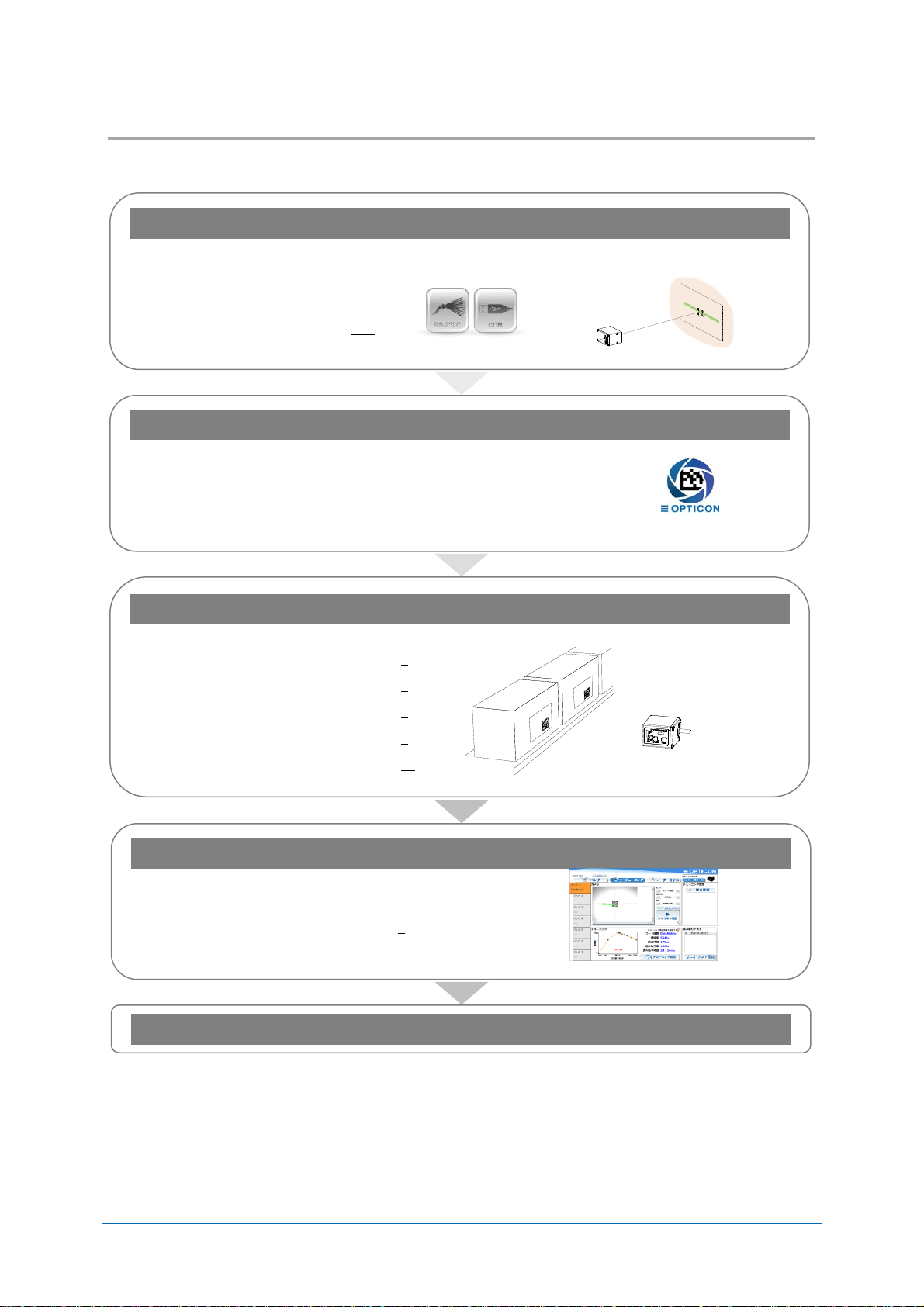
Flow to Integrate
1. Examine and Select the Scanner
Examine technical introduction in
advance.
“Communication”
“Reading position and focus model”
● Before using
→ (Refer to 2)
● Product specification
overview
→(Refer to 11.2)
2. Download Tools
According to the operation, download necessary tools from our website.
● Install condition image confirmation, tuning and
other settings.
→ ”UniversalTuningTool”
UniversaTuningTool
● For USB-COM
→ ”USB Driver”
3. Fixing Position and Setting for operation
Confirm the optimun setting according to the operation.
● Configurations
→ (Refer to 3)
● Interface
→ (Refer to 5)
● Reading and Timing
→ (Refer to 6)
● Read options
→ (Refer to 8)
● String Options
→ (Refer to 10)
4. Tuning and Testing
Tune and test in the acturla envirioment.
● Tuning and bank function
→ (Refer to 7)
Integrate
1.3
Flow to Integrate for Industrial Uses 1.3.1
Flows to integrate the scanner for industrial use are described below.
Chapter-1
Abstract
Page 15

NLV-5201 User's Manual
5
1st
Flow to Integrate for General Uses
1. Examine and Select the Scanner
Examine technical introduction in
advance.
“Communication”
“Reading code”
● Before using
→ (Refer to 2)
● Product specification
overview
→ (Refer to 11.2)
2. Download Tools
According to the operation, download necessary tools from our website.
● Setting, Image acquisition, confirm
communication
→ “UniversalConfig”
UniversalConfig
● USB-COM
→ “USB Driver”
3. Setting and Testing
In the actual enviroment, evaluate the optimum setting according to the operation and perform a
reading test.
● Configurations
→ (Refer to 3)
● Indicator
→ (Refer to 4)
● Interface
→ (Refer to 5)
● Code Options
→ (Refer to 9)
● String Options
→ (Refer to 10)
● Read Options
→ (Refer to 8)
4. Create Setting Menu
Create a 2D menu code suitable for operation.
● 2D menu code
→ (Refer to 3.1.2)
Integrate
1.3.2
Flows to integrate the scanner for general use are described below.
Chapter-1
Abstract
Page 16

NLV-5201 User's Manual
6
1st
2 Before Using
Following explains the items required before using.
2.1 Model Details
2.2 Package Contents
2.3 Connect to the Host
2.4 How to Read
2.5 Depth of Field and Focus Type
2.6 Detailed View
2.7 Operation Mode and Control Panel Description
2.8 Operation Transition
2.9 Installation of the Scanner
2.10 Scan Area
2.11 Scanned Media and Placement
2.12 When Placing Exit Window
Chapter-2
Before Using
Page 17

NLV-5201 User's Manual
7
1st
Model Details
Model
name
Focus Interface
Cable length
Optional
AC Adapter
NLV-5201
None
or
-HD
or
-UD
-RS232C(LE)
or
-USB
or
-USB-COM
or
-RS232C(9P)
None
None
or
-RS232C
+PS
Standard
Description
NLV-5201-RS232C(LE)
Standard focus, RS-232C loose end
NLV-5201-USB
Standard focus, USB-HID
Symbol
Description
None
Standard focus model (focus distance: 113 mm)
-HD
High density focus model (focus distance: 63 mm)
-UD
Ultra-high density focus model (focus distance: 43 mm)
Symbol
Description
-RS232C(LE)
RS-232C loose end cable (open wires, no connector)
-USB
USB cable is connected and interface default setting is USB-HID.
-USB-COM
USB cable is connected and interface default setting is USB-COM.
-RS232C(9P)
RS-232C cable (power supply input connected to D-sub 9 pin 9)
-RS232C
RS-232C cable with power pigtail (external AC power supply spec) is
connected.
Symbol
Description
None
Cable length 1.5 m
Symbol
Description
None
AC adapter not included.
+PS
AC adapter for RS-232C external power supply is included.
2.1
The NLV-5201 model name is constructed by a combination of following.
Standard 2.1.1
The following specs are the standard products.
Chapter-2
Before Using
Note: Other combinations only as special order, please contact sales offices for this.
Model Description 2.1.2
Focus
Interface Cable
Cable Length
Optional AC adapter
Page 18

NLV-5201 User's Manual
8
1st
Package Contents
Scanner with USB cable
NLV-5201 Quick Start Guide
(1 copy)
Scanner with RS-232C (loose end) cable
NLV-5201 Quick Start Guide
(1 copy)
USB-HID / USB-COM Interface Model
RS-232C Interface Model
2.2
Following items are packed to this product. Please check before using.
Chapter-2
Before Using
Following are included to USB interface model.
Following are packed to RS-232C interface model.
Page 19

Chapter-2
NLV-5201 User's Manual
9
1st
Host
USB Connector
X X X X X X
1500
Φ 3.8
[Unit: mm]
USB plug A
USB-COM/ USB-HID Interface Connection Diagram
Before Using
Connect to the Host
2.3
This section describes how to connect each interface to the host.
For interface setting details, refer to “5. Interface”
For details of installing the scanner, refer to “Installation of the Scanner”.
Connecting with the Host device
Connect interface connector to the host. When power is on, the scanner makes startup sound.
After startup sound is completed, the scanner will be ready for reading.
* USB-COM and USB-HID interface can be changed by the setting.
* For the USB-COM interface model, the Opticon USB-COM driver must be installed on your host device.
* While using USB-COM and not connected to the host, the scanner makes an error sound when reading.
Page 20

Chapter-2
NLV-5201 User's Manual
10
1st
Cable Color
Signal Name
Notes
Red
VCC
Power-supply voltage 4.5-5.5V (Typ.5V)
Brown
Trigger
External trigger input terminal
Yellow
OK
External OK output terminal
Orange
NG
External NG output terminal
Black
S-GND
Gray
RTS Blue
CTS Green
TxD White
RxD (Black)
Shield GND
Heat shrinkable tube
X X X X X X
1500
60
Φ 3.8
AWG28
[Unit: mm]
Host
RS-232C
Communication connector
Barcode
reader main
circuit
VCC
DC 5V
+
Load
MAX DC 24V
+
TxD
RxD
RTS
CTS
OK / NG
Trigger
S-GND
F-GND
TxD
RxD
CTS
RTS
External
device
NLV-5201
RS-232C (Loose End) Interface Connection Diagram
Before Using
Loose end Pin Assignment
Loose end Circuit
Page 21

NLV-5201 User's Manual
11
1st
How to Read
2.4
The scanner read target code by acquiring the image.
Reading starts by the following method.
1. Send command trigger “Z” via serial communication. (RS-232C, USB-COM)
2. Turn ON external trigger input. (RS-232C loose end)
3. Detect target to read in auto trigger mode.
4. Press trigger key. (Used when testing and maintenance etc.)
Chapter-2
Before Using
Reading Reference Standard mode (SR): Approx. 113 cm Scan Area (Refer to 2.10)
Distance (Refer to 2.5.1)
High Resolution model (HD): Approx. 63 cm
(Refer to 2.5.2)
Ultra High Resolution model (UD): Approx. 43 mm
(Refer to 2.5.3)
Page 22

NLV-5201 User's Manual
12
1st
Depth of Field and Focus Type
0.127mm (5mil)
53 126
0.254mm (10mil)
52
237
0.508mm (20mil)
69
433
0.20mm (7.9mil)
191
62
0.33mm (13mil)
50
291
0.169mm (6.7mil)
49
146
0.254mm (10mil)
42
211
0.169mm
60
111
0.381mm (15mil)
22
250
0.169mm (6.7mil)
62
116
0.254mm (10mil)
173
43
0
50 100 150
200 250
300
0
50
50
25
25
75
100
[Unit: mm ]
100 75
Code 39
Code 128
EAN/UPC
PDF417
QR Code
Data Matrix
2.5
Select the focus type according to reading distance and code resolution.
Standard Model (SR) Depth of Field 2.5.1
Chapter-2
Before Using
* The depth of field is the typical value measured by tilting the test chart 15° from the optical axis. (25C°)
* Refer to 11.2.2 Technical Specifications Standard Model Reading Depth of Field for specified value.
Page 23

NLV-5201 User's Manual
13
1st
High Resolution Model (HD) Depth of Field
0
50 100
150
200
0 50
50
25
75
75
25
Code 39
Code 128
EAN/UPC
PDF417
QR Code
Data Matrix
0.076mm(3.0mil)
45 72
0.127mm(5.0mil)
35
119
0.254mm (10mil)
55
179
0.20mm (7.9mil)
159
68
0.33mm (13mil)
48
200
0.127mm (5.0mil)
39
109
0.254mm (10mil)
46
154
0.127mm (5.0mil)
43
91
0.381mm (15mil)
24
180
0.127mm (5.0mil)
48
78
0.254mm (10mil)
139
28
[ Unit:mm ]
2.5.2
Chapter-2
Before Using
* The depth of field is the typical value measured by tilting the test chart 15° from the optical axis. (25C°)
* Refer to 11.2.2 Technical Specifications High Resolution Model (HD) Reading Depth of Field for specified value.
Page 24

NLV-5201 User's Manual
14
1st
Ultra High Resolution model (UD) Depth of Field
0
0
25
50
[Unit: mm ]
Code 39
EAN/UPC
QR Code
Data Matrix
0.076mm(3mil)
28
65
0.127mm(5mil)
23
82
0.254(10mil)
53
108
0.33mm(13mil)
50
0.084mm(3.3mil)
33
55
0.381mm(15mil)
22
109
25
50
75
100
2550
120
0.084mm(3.3mil)
35
55
0.254mm(10mil)
22
86
2.5.3
Chapter-2
Before Using
* The depth of field is the typical value measured by tilting the test chart 15° from the optical axis. (25C°)
* Refer to 11.2.2 Technical Specifications Ultra High Resolution model (UD) Reading Depth of Field for specified
value.
Page 25

NLV-5201 User's Manual
15
1st
Detailed View
No.
Name
Description
1
Scan Window
Light paths of the imager, LED illumination and aiming. Ensure that
the lens is free from dust and dirt before scanning.
2
Mounting Holes
Screw holes that can be used to mount the scanner. Two holes on
the bottom and side. Refer to the mechanical drawing for the
mounting holes dimension.
The screw hole is M3, effective depth 3.5mm.
3
Control Panel
Control panel to execute Test mode, Tuning mode and Aiming mode.
Can also select the bank.
4
Buzzer Holes
Sound from a built-in buzzer comes out through these holes. When
they are covered, the buzzer sound will be diminished. The sound
varies depending on the settings. Buzzer sound settings are
configurable for frequency, loudness and duration.
5
Status LEDs
Indicates status by the combination of 3-color LEDs (red, orange,
green).
Refer to 2.7.3 LED Indicator Specifications for detail.
6
Trigger Key
Default is trigger key. When selecting mode, it operates as execution
key.
7
Mode Key
The key to select and cancel the mode.
Shift to bank select mode by long press.
Mode key can be disabled, refer to 3.3.9 for detail.
X X X X X X
2. Mounting Holes
1. Scan Window
4. Buzzer Holes
7. Mode Key
6. Trigger Key
5. Status LED
3. Control Panel
2.6
Chapter-2
Before Using
Page 26

Chapter-2
NLV-5201 User's Manual
16
1st
Mode name
Mark
Description
Normal
mode
-
Following are use as reading trigger in a readable state like operation.
・Command trigger by serial communication (USB-COM/RS-232C)
・External trigger signal (RS-232C)
・Auto trigger
・Trigger key
Test mode
TEST
Used when testing the read rate.
The read rate is displayed on the indicator LED every 10 times.
Tuning mode
TUNE
When reading distance and the code to read is fixed, reading will
stabilized by setting the optimum exposure.
When the tuning is successes, code limited and exposures setting etc.
are registered to the current bank. Also, the reading rate is displayed on
the LED indicator.
Bank
-
Area to register the exposure etc. adjusted in the tuning mode. 1-7 can
be register to the bank, default is 1.
Aiming mode
AIM
Aiming lights and if code can be read, displays whether the code is close
to the center coordinate of the image sensor to LED indicator.
Buzzer Holes
Mode Key
Trigger Key
Status LED
Control Panel
Before Using
Operation Mode and Control Panel Description
2.7
Normally, the scanner is operated by serial communication control, but simple operation setting by the
control panel is also available.
Operation Mode 2.7.1
Page 27

NLV-5201 User's Manual
17
1st
Control Panel Operation Specifications
LED Indication
Mode Key
Trigger Key
Operation
Mode
Operation description
Trigger Key
for reading
Normal
Normal operation status.
Press once
(within 2 sec)
Mode
transition by
pressing once
Test
Used when testing the read rate.
The read rate is displayed on the indicator LED
every 10 times.
Press twice
(within 2 sec)
Mode
transition by
pressing once
Tuning
Tuning automatically perform optimum exposure
setting etc. according to the read code. When the
tuning is successes, the code is limited, and
exposures setting etc. are registered to the current
bank. Also, the reading rate when tuning is
successes is displayed on the LED indicator.
Press 3 times
(within 2 sec)
Mode
transition by
pressing once
Aiming
In the aiming mode, aiming lights and if code can
be read, displays whether the code is close to the
center coordinate of the image sensor to indicator
LED.
Press 4 times
(within 2 sec)
Press
2 seconds
or more
(Press again
to select)
Mode
transition by
pressing once
Bank
selection
By pressing the mode key for more than 2
seconds, the bank currently used will be display on
the LED. Pressing the mode key again, bank
becomes selectable in order, and by pressing the
trigger key, the bank displayed becomes effective.
Press both key at same
time for 5 seconds,
becomes initialization
standby. And initialize by
pressing trigger key again.
Initialize
Pressing mode key and trigger key at same time
for 5 seconds, it enters to the initialization standby.
Initialized by pressing trigger key with that status,
and initialization standby will be cancel by pressing
mode key.
2.7.2
Operation specification of the control panel allocated on the side of housing are as follows.
Chapter-2
Before Using
Page 28

Chapter-2
NLV-5201 User's Manual
18
1st
Status
Reading success
Waiting for
USB communication
Communication/
Reading error
LED
indication
Reading
rate
0 - 40 %
50 - 70 %
80 - 90%
100%
Central
coordinate
Within 1/2 image
Within 1/4 image
Within 1/8 image
Within 1/16 image
LED
indication
Bank No.
No.1
No.2
No.3
No.4
No.5
No.6
No.7
LED
indication
: OFF
: Blinking
: ON
1/2 Image
1/4 Image
1/8 Image
1/16 Image
Code center
Center position
Before Using
LED Indicator Specifications
2.7.3
The status LED’s indicate the reading result and USB communication status. In read rate mode, the
reading success rate is indicated by these three 3-color LED’s. Below is a more in-depth description
on these LED’s.
Normal mode status LED indication
“Test mode”, “Tuning mode” and “Aiming mode” LED indication
Test and tuning display the reading rate for 10 times.
*Judgement range at aiming.
“Bank. No.” LED indication
The LED of the bank currently used will blink by pressing the mode key for more than 2 seconds.
* Status LED legend
Page 29

NLV-5201 User's Manual
19
1st
Buzzer and LED Indicator
Item
Rumble timing
Tone interval
LED color
Enable/Disable
Start-up sound
When powered on.
Low - Low middle 2 time -
Middle tone
3 color
Combination
Configurable
(Default: Enable)
Good read sound
When reading successes
Middle tone 1 time
Light blue
Configurable
(Default: Enable)
Data transmission
error
In USB, when connection is not established.
(Middle - Middle low tone)
6 times
Red
Enable (Fixed)
Batch reading
Intermediate
sound
When one code is read and if it does not yet
meet the conditions to output data in batch
reading or concatenated code reading.
Short High tone 1 time
None
Configurable
(Default: Enable)
Read timeout
sound
When code is not read within the effective
time period.
Low tone 2 times
Red
Configurable
(Default: Disable)
1D ZZ menu
Reading sound
When reading start ZZ menu code.
Middle - Middle low -
Middle high tone
Yellow
Enable (Fixed)
When reading defined menu code.
Middle - Middle low -
Middle-high tone
Yellow
Enable (Fixed)
When reading not defined menu code.
Low tone 2 times
Red
Enable (Fixed)
When reading end ZZ menu code.
Middle - Middle low -
Middle-high tone
Yellow
Enable (Fixed)
When save setting is complete
(Middle - Middle low -
Middle high tone) 3 times
None
Enable (Fixed)
2D menu
Reading sound
When reading 2D menu code.
Middle - Middle low -
Middle high tone
Yellow
Enable (Fixed)
When save setting is complete.
(Middle - Middle low -
Middle high tone) 3 times
None
Enable (Fixed)
High temperature
protection mode
If internal temperature exceeds a certain
temperature, reading operation becomes
disabled. While in this mode, it beeps with a 3
seconds interval.
High tone 2 times
Orange
Enable (Fixed)
Buzzer Holes
Status LED
2.7.4
Buzzer sound and lighting color of LED indicates status of the scanner.
The scanner status, buzzer sound and status LED are described as below.
Chapter-2
Before Using
* Low: around 1000 Hz, Low middle: around 1000-2000 Hz, Middle low: around 2500 Hz, Middle: around 3000 Hz,
Middle high: around 3500 Hz, High: around 4000Hz.
* Refer to 4. Indicator for setting detail.
* Above is the definition of the representative status and does not indicate all of the operations.
Page 30

NLV-5201 User's Manual
20
1st
Operation Transition
Status
Description
Read
Acquiring image and reading is in progress with the warm white LED and
green aiming LED on.
Standby
Can start reading by serial command, pushing side trigger or the external
trigger input becomes active.
Reading operation stop*
The reading operation can be stopped by a successful decode, a stop
command, or a timeout period after release of the trigger.
Power-OFF
Standby
Read
Non-Operation
Power
applied
Transition command
Recovery
command
Trigger
Scanning completes
or
Time out
2.8
Following are the operation status transition of the scanner.
Normal Trigger 2.8.1
Chapter-2
Before Using
Status Description
* "Reading operation stop” is configured using commands. This cannot be done while using USB-HID interface.
Page 31

NLV-5201 User's Manual
21
1st
Auto Trigger
Power-OFF
Standby
[Auto Trigger]
Auto Trigger Sleep
Configured
(Default is 60 seconds)
Power
applied
Read
Scanning completes
or
Time out
Non-Operation
Detect target
Detect target
Transition command
Recovery
command
Status
Description
Read
Processes reading. Illumination fully ON
Auto trigger standby
When the target is within the scan area and detected, the scanner
starts the reading mode. AIM pulses.
Auto trigger sleep
Auto-trigger mode will sleep after 60 seconds (default time). This sleep
time can be re-configured or disabled.
Reading operation stop*
Operation of the scanner is stopped.
2.8.2
Chapter-2
Before Using
Status Description
* "Reading operation stop” is configured using commands. This cannot be done while using USB-HID interface.
Page 32

Chapter-2
NLV-5201 User's Manual
22
1st
Read Operation
Enable
Read Operation
Disable
Read operation enable command
Read operation disable command
Before Using
Operation Invalid Transition Diagram
2.8.3
For USB-COM and RS-232C, scanner operation can be disabled by command’s serial communication.
When disabled, auto trigger operation becomes invalid.
Refer to 3.3.6 for setting command.
Page 33

Chapter-2
NLV-5201 User's Manual
23
1st
Mounting Holes
M3 Depth 3.5
41.1
33
10.9
12
24
35.9
15
8
18.8
Mounting Holes
M3 Depth 3.5
11
2.6
X X X X X X
13.11
[Unit: mm]
Before Using
Installation of the Scanner
2.9
The installation of the scanner is described as below.
・Mount the scanner using the assigned screw holes on the bottom or side.
・Do not screw down further than the limitation of its depth.
・The scanner’s anti-shock reliability is confirmed only in case impulse (acceleration) is applied via the
contact surface. However, the scanner cannot withstand direct shock since it consists of precise
optical elements.
NLV-5201 Installation
Recommend screw type: M3
Recommend torque: Less than 20 Ncm.
Maximum screw depth: 3.5 mm from the mounting surface of the scanner.
Dimensions: Approx. 41.1 (W) ×33.0 (H) ×24.0 (D)
Weight: Approx. 30 g (excluding cable)
Cable: 1.5 m
Please contact sales for 3D CAD data.
Page 34

NLV-5201 User's Manual
24
1st
Scan Area
L: Distance from the front edge of scanner
[mm]
40
60
80
100
120
140
160
180
Horizontal FOV
[mm]
29.6
43.4
57.1
70.9
84.7
98.5
112.3
126.0
Vertical FOV
[mm]
22.1
32.4
42.7
53.0
63.3
73.6
83.9
94.2
Horizontal image width
Vertical image width
Aiming width
Distance:L
2.10
Image range is as follows.
Image Range 2.10.1
NLV-5201 image range is as follows.
Install a frame with sufficient clearance for the field of view.
Chapter-2
Before Using
The range is ±5% from the following values.
Image Range
* The table above shows the field of view which should not be obstructed by any parts of a housing.
Page 35

Chapter-2
NLV-5201 User's Manual
25
1st
Horizontal Field of View
Illumination LED
Vertical Field of View
Illumination LED
Vertical
Horizontal
Standard (SR) Focus (113 mm)
Aiming (LED)
Aiming (LED)
HD Focus (63 mm)
UD Focus (43 mm)
Before Using
2.10.2
Optical Path
Install the Exit Window with sufficient clearance for the field of view, LED illumination and LED aiming.
Provide the exit window with sufficient clearance with respect to the optical path, as depicted below.
*Obtain the image in the actual environment and evaluate it. The software tools for image capture can be found
on the Opticon website.
Page 36

Chapter-2
NLV-5201 User's Manual
26
1st
θ
L
Background
Scanned target
Before Using
Scanned Media and Placement
2.11
When an object is being scanned, there are conditions where specular reflection of the LED
illumination and intense ambient light can occur easily.
Solution for Specular Reflection of the LED Illumination 2.11.1
Problem: Glossy label
Specular reflection of the LED illumination from the scanner can occur when the target label is on a
highly reflective surface.
Solution:
Specular reflection does not occur when an angle is created between the scanner and the target label
as shown in the figure below. The conditions for the occurrence of specular reflection depend on the
distance L and the inclination angle θ. The recommended inclination angle is about 15 degrees. Note
that as the angle becomes bigger, it becomes more difficult to read the target label.
*For the background, use non-specular surface within the image range.
*Obtain the image in the actual environment and evaluate it. The software tools for image capture can be found
on the Opticon website.
Page 37

Chapter-2
NLV-5201 User's Manual
27
1st
Shade
Scanned target
Before Using
2.11.2
Solution for Specular Reflection of the External Illumination
Problem: Label on metal, code on the display
Strong ambient light (fluorescent and sunlight) causes a specular reflection on metal surface or glass
surface of display
Solution:
It is recommended to shield the reading position from strong ambient light.
*Obtain the image in the actual environment and evaluate it. The software tools for image capture can be found
on the Opticon website.
Page 38

Chapter-2
NLV-5201 User's Manual
28
1st
LED illumination appears to the exit window
Before Using
Exit Window Placement
2.12
LED illumination appears to the exit window depending on the exit window material and placement.
The distance and angle limitation to prevent this are described below.
Exit Window Material 2.12.1
Below is a list of recommendations for constructing the exit window. These recommendations help to
prevent reflection from the LED illumination off the exit window and help to prevent degradation of the
image by scratches and dirt.
● For the best optical quality, use an acrylic material (cast or extruded)
● Select a high-quality achromatic acrylic material with a smooth, flat surface without scratches and
dents.
● Use acrylic material with an anti-reflective (AR) coating applied to both sides.
● Apply an anti-scratch coating to the surface of the exit window to protect it from scratches during
operation.
● Hard coated acrylic sheets are readily available. Such a coating greatly enhances anti-scratch
properties without degrading the optical characteristics of the acrylic material.
Recommended acrylic material:
Nitto Jushi Kogyo Co., Ltd. Clarex Precision Thin Sheet
MITSUBISHI CHEMICAL CO., LTD. Shinkolite
Page 39

Chapter-2
NLV-5201 User's Manual
29
1st
➔
➔
➔
Exit window
Scanned target
18
°
18
°
Before Using
2.12.2
Solution for Specular Reflection of the Illumination
Placement of the exit window has limitation on the distance and angle to prevent reflection of the LED
illumination.
To avoid the reflection of LED, tilt the scanner and exit window for about 18 degrees in vertically.
* Obtain the image in the condition range to be used and design placement so that there is no reflection of the
LED illumination.
* Keep a minimum clearance between the scanner and the exit window of 1mm because of the dimensional
tolerances of the mounting holes
* Use of AR coated material for the exit window is recommended.
* External light is not factored in.
* Confirm that there is no reflection of the LED illumination off the exit window by acquiring images from the
scanner.
Page 40

Configurations
NLV-5201 User's Manual
30
1st
3 Configurations
This chapter explains the scanner configuration, default setting and saving setting, and basic
commands.
3.1 Configuring with Commands
3.2 Command Packet Sending Precautions
3.3 Basic Commands
Chapter-3
Page 41

Chapter-3
NLV-5201 User's Manual
31
1st
Command Header*2
Command ID*1
Command Terminator*2
<ESC>
(0x1B)
None
1-2 digits (ASCII)
<CR>
(0x0D)
[(0x5B)
3 digits (ASCII)
Configurations
Configuring with Commands
3.1
The scanner can be configured by sending commands via the serial interface or by reading 1D or 2D
menu labels. This section describes the serial commands.
Command Packet 3.1.1
The command packet, from header to terminator, is defined as below.
*1 It is possible to send multiple command IDs between a single header and terminator, except for single digit IDs.
*2 A combination of command header <STX>(0x02) and terminator <ETX>(0x03) is also possible.
Input examples:
1-digit command <ESC>Δ<CR>
2-digit command <ESC>ΔΔ<CR>
3-digit command <ESC>[ΔΔΔ<CR>
Two 2 digit commands <ESC>ΔΔΔΔ<CR>
2 and 3 digits command <ESC>ΔΔ[ΔΔΔ<CR>
Command can be sent via “UniversalConfig” Command can be sent via “UniversalTunigTool”
* Commands entered in the “command:” box of this utility do not require the beginning command header <ESC>.
The command or commands will be sent to the reader upon a ENTER key or a click of the [Send] button.
Page 42

Chapter-3
NLV-5201 User's Manual
32
1st
“@MENU_OPTO”
(Start key)
“@”
(Separator)
“ZZ”
(Start menu)
“@”
(Separator)
← Multiple sets allowed
“Any menu command”
(U2 etc)
“@”
(Separator)
“ZZ”
(END menu)
“@”
(Separator)
“OTPO_UNEM@”
(Stop key)
Print
Configurations
Configuring with 2D Menu
3.1.2
A single 2D menu code can contain multiple settings that will be processed in order, in one operation.
Therefore, you can configure the scanner with multiple settings by reading only one 2D menu code.
Scanning a 2D menu code will always perform a ‘save settings’ upon completion, so a Z2 command to
save current settings is not needed.
Data Packet:
@MENU_OPTO@ZZ@MenuCommand 1@MenuCommand 2@ZZ@OTPO_UNEM@
● 2D menu code can be created at “UniversalConfig”.
*Please contact sales offices for the tools.
Page 43

Chapter-3
NLV-5201 User's Manual
33
1st
Scan SET menu code (ZZ). The scanner now enters menu mode.
Scan one or more desired options.
Read END menu code (ZZ). All the settings are saved in non-volatile memory.
Print
Configurations
Configuring with 1D Menu Code
3.1.3
By scanning a series of 1D menu codes specially designed to configure the required functions, you
can set up the scanner to optimize its performance for your particular application.
The basic procedures are as follows:
Multiple menu codes can be read when you want to configure more than one option.
* 1D Menu codes encode an ID consisting of two to five alphanumeric characters. 1D Menu codes are Code39
labels with modified start/stop characters and therefore the scanner will not acknowledge a 1D menu code as a
normal barcode.
● Menu barcode can be created at “UniversalConfig”.
*Please contact sales offices for the tools.
Page 44

NLV-5201 User's Manual
34
1st
Command Packet Sending Precautions
Active Settings
Settings that is currently active.
(Including newly added settings from power on)
Startup Settings
Custom Settings
The setting to be read when power is turned on.
Custom setting to be saved on another memory area.
Factory Default Settings
Default setting is the same as the initial setting described in this manual.
Various interfaces require switching setting.
Item
Command
Interface
Description
Remark
Factory
Default
Settings
SU
USB-HID
Restore USB-HID to factory default settings
[C01
USB-COM
Restore USB-COM to factory default settings
U2
RS-232C
Restore RS-232C to factory default settings
Custom Settings Active Settings
Each interface
Factory Default
Settings
Start-up
Settings
Readout custom setting
Command “[BAP”
Save custom setting
Command “[BAQ”
Readout factory default settings
Command “SU”, “[C01”, “U2”
Power-ON
/Software reset
Start-up setting
Save command “Z2”
Setting command (Serial communication)
3.2
Following are the scanner setting method.
Setting value, writing and reading diagram
Chapter-3
Configurations
* Menu barcode and 2D menu code setting are always saved in “Startup setting”.
* When updating the firmware, status of interface will remained, but “Startup setting” and “Custom setting” will be
initialized.
Each interface Default Setting 3.2.1
The Active Settings can be returned to the factory default settings. Set the command that corresponds
to the interface being used.
Page 45

Chapter-3
NLV-5201 User's Manual
35
1st
Item
Command
Description
Remark
Save settings
Z2
Save the Active Settings as Startup Settings
Command only
Item
Command
Description
Remark
Custom settings
[BAP
Read out Custom Settings
[BAQ
Save to Custom Settings
Configurations
Save Settings
3.2.2
The Active Settings can be written into the “Startup Settings”.
* Place “Z2” at the end of command packet to be saved.
* Saving settings for more than 30,000 times may destroy memory. Avoid saving every time.
* There are options that will not be enabled until “Save settings” is sent, such as baud rate setting.
Custom Setting 3.2.3
* Place “[BAQ” at the end of command packet to be saved.
* To save both “Custom settings” and “Active Settings” at same time, send “[BAQZ2”.
* Custom settings for more than 30,000 times may destroy memory. When setting frequently, avoid saving every
time.
Page 46

Chapter-3
NLV-5201 User's Manual
36
1st
Item
Command
Description
Default
ACK/NAK
WC
Enable ACK/NAK for serial commands
WD
Disable ACK/NAK for serial commands
Item
Command
Description
Remark
Diagnostics
Z1
Transmit software version
ZA
Transmit ASCII printable string
YV
Transmit ASCII control string
Item
Command
Description
Default
Enable/Disable 2D menu code
[D1Y
Enable 2D menu code
[D1Z
Disable 2D menu code*
Item
Command
Description
Default
Enable/Disable 1D menu code
[DFB
Q0
Q1
Enable when using trigger key.
Q0
Q0
Disable when using trigger key.*
Q1
Q1
Enable when using external trigger signal.
Q1
Q0
Disable when using external trigger signal.*
Q2
Q1
Enable when using command trigger or auto trigger.
Q2
Q0
Disable when using command trigger or auto trigger.*
Configurations
Basic Commands
3.3
Following are the basic commands for the scanner.
ACK/NAK for Serial Commands 3.3.1
When "ACK/NAK for serial commands" is enabled, the scanner will send an ACK (0x06) when a
command is received and accepted, and a NAK (0x15) when a command is rejected.
Diagnostic Commands 3.3.2
These commands can be used to get diagnostics information from the scanner.
Enable/Disable 2D Menu Code 3.3.3
To enable/disable the processing of 2D menu codes, use the settings below.
Setting ‘Disable 2D menu codes’ is recommended when 2D menu codes are not used.
* Indicates reading 2D menu code as normal 2D code. Therefore, 2D menu code data will be output when reading
success.
Enable/Disable 1D Menu Code 3.3.4
To enable/disable the decoding of 1D menu codes, use the settings below.
Setting ‘Disable 1D menu codes’ is recommended when 1D menu codes are not used.
* Indicates that 1D menu code reading is prohibited.
Page 47

Chapter-3
NLV-5201 User's Manual
37
1st
Item
Command
Description
Default
Horizontal mirrored
image
[EFU
Disable horizontal mirrored image configuration
[EFV
Enable horizontal mirrored image configuration
Vertical mirrored
image
[E8J
Disable vertical mirrored image configuration
[E8I
Enable vertical mirrored image configuration
Style
Commands
Horizontal mirror
Vertical mirror
Normal image
[EFU[E8J
Disable
Disable
Horizontal mirror image
[EFV[E8J
Enable
Disable
Vertical mirror image
[EFU[E8I
Disable
Enable
180° rotated image
[EFV[E8I
Enable
Enable
Horizontal
Mirror
Horizontal
Mirror
Vertical
Mirror
Vertical
Mirror
①Normal Image
③Vertical Mirrored Image
②Horizontal Mirrored Image
④180° Rotated Image
Top (Device)
Bottom (Device)
[①Normal image]
[②Horizontal mirror image]
[③Vertical mirror image]
Mirror
[④180° rotated image]
Right (Device)
Left (Device)
Mirror
Top (Device)
Bottom (Device)
Top (Device)
Bottom (Device)
Configurations
Image Settings
3.3.5
When the scanner is mounted upside down, it should rotate the sensor data by 180º. This
configuration is required especially for image acquisition and OCR reading.
When an external mirror is installed in front of the scan engine, the scanner should mirror the sensor
data. Two options are available for that, horizontal mirror and vertical mirror.
Configuration commands
Page 48

Chapter-3
NLV-5201 User's Manual
38
1st
Item
Command
Description
Default
Remark
Enable/Disable
Reading operation
[EAT
Enable module reading operation
Command only
[EAU
Disable module reading operation
Command only
Item
Command
Description
Remark
Buzzer
B
Sound the good read beep
Command only
E
Sound the error beep
Status LED
L
Flash the status LED
N
Flash the error status LED
Item
Command
Description
Remark
Software reboot
RV
Reboot the scanner
Item
Command
Description
Default
Enable/Disable Mode key
[EHB
Q0
Disable mode key
Q1
Enable mode key
Mode Key
Control Panel
Configurations
Disable Reading Operation
3.3.6
To enable/disable the processing of reading, use the settings below.
Auto trigger become invalid by setting this disable reading. In this setting, menu labels cannot be read,
only commands via serial communication are supported.
Buzzer and Indicator 3.3.7
These commands reflect “4.1.1 Buzzer” and “4.1.2 Good Read Buzzer”.
Reboot the Scanner 3.3.8
Use this command to restart the scanner.
Enable/Disable Mode Key 3.3.9
Page 49

Chapter-3
NLV-5201 User's Manual
39
1st
Item
Command
Description
Remark
Direct input
numerical values
Q0
0
Input in a
specified
format
Q1 1 Q2 2 Q3 3 Q4
4
Q5 5 Q6
6
Q7 7 Q8 8 Q9
9
Configurations
Direct Numerical Input Command 3.3.10
When a command requires additional numerical input, the commands below can be used. Use these
in one packet together with the command that requires the numerical input.
Page 50

NLV-5201 User's Manual
40
1st
4 Indicator Options
This chapter describes the options for Buzzer and Good Read LED.
4.1 Buzzer
4.2 Status LED
4.3 Good Read Aiming
4.4 Indicator in General
Chapter-4
Indicator Options
Page 51

Chapter-4
NLV-5201 User's Manual
41
1st
Item
Command
Description
Default
Buzzer loudness
T0
Buzzer loudness : Maximum
T1
Buzzer loudness : Loud
T2
Buzzer loudness : Normal
T3
Buzzer loudness : Minimum
Item
Command
Description
Default
Buzzer
Disable/Enable
W0
Disable buzzer
W8
Enable buzzer
Item
Command
Description
Default
Buzzer duration
W7
Buzzer duration: 50 ms
[EFW
Buzzer duration: 75 ms
W4
Buzzer duration: 100 ms
W5
Buzzer duration: 200 ms
W6
Buzzer duration: 400 ms
Item
Command
Description
Default
Buzzer tone (*)
W1
Middle frequency buzzer (3000 Hz)
2600 Hz
W2
2 steps buzzer (high - low buzzer)
W3
2 steps buzzer (low - high buzzer)
Item
Command
Description
Default
Buzzer tone
frequency
setting
[DF0
Qa
Qb
Qc
Qd
Numerical setting of
buzzer tone frequency
2600 Hz
(1-9999)
(1000a+100b+10c+d)[Hz]
Indicator Options
Buzzer
4.1
Buzzer operation settings are described below.
Buzzer Loudness 4.1.1
The buzzer loudness can be set with these options, which is applied to all buzzers.
Good Read Buzzer
4.1.2
The good read buzzer is activated when a code is successfully read and the data is output.
3 types of tone and 5 types of duration are configurable. The good read buzzer can also be disabled.
● Buzzer Disable/Enable
● Buzzer duration
● Buzzer tone
* The good read buzzer tone (frequency) can be set with numerical parameters by inputting the command
followed by a 4-digit numerical command.
Frequency range normally use is 2000 to 4000 Hz. The scanner most resonance around 2750 Hz.
Page 52

Chapter-4
NLV-5201 User's Manual
42
1st
Item
Command
Description
Default
Remark
Startup buzzer
GD
Disable startup buzzer
Enabled only
with “Z2”
GC
Enable startup buzzer
Enabled only
with “Z2”
Item
Command
Description
Default
Read timeout buzzer
[EAP
Disable read timeout buzzer
[EAQ
Enable read timeout buzzer
Item
Command
Description
Default
Intermediate buzzer
[EBY
Q0
Disable intermediate buzzer
Q1
Enable intermediate buzzer
Indicator Options
Start-up Buzzer
4.1.3
This setting determines whether the scanner emits a beep when it is powered on.
Read Timeout Buzzer 4.1.4
In case a code is not read within the timeout period, an error buzzer sounds when the read operation
ends.
Intermediate Buzzer 4.1.5
When one code is decoded, an intermediate buzzer sounds to indicate that the code is decoded but it
does not yet meet the conditions to output data.
For instance, suppose five-codes reading is set in buffer mode, the intermediate buzzer then sounds
after the decoding of the 1st, 2nd, 3rd and 4th code and a good read buzzer finally sounds when the
last code is decoded after which the data is output. The data is not output when the 1st to 4th codes
are decoded but reading of each code can be confirmed by the intermediate buzzer. When the good
read buzzer is disabled, this setting will be forcibly disabled.
* Intermediate buzzer frequency: 5000 Hz (5 KHz), duration: 10 ms
Page 53

Chapter-4
NLV-5201 User's Manual
43
1st
Item
Command
Description
Default
Status LED
T4
Disable indicator
[XT8
Indicator duration: 100 ms
T5
Indicator duration: 200 ms
T6
Indicator duration: 400 ms
T7
Indicator duration: 800 ms
Indicator Options
Status LED
4.2
Each status LED operation settings are described below.
Status LED Lighting Time 4.2.1
The status LED lights up after a code was successfully decoded and the data was output. This can be
disabled or set for several durations.
Page 54

NLV-5201 User's Manual
44
1st
Good Read Aiming
Item
Command
Function
Description
Default
Good Read Aiming
[EF3
Qa
Qb
Qc
a
Setting
items
0:Indicator frequency
1:First indicator duration
after reading
b
Numerical
setting
10b + c
Indicator frequency
00-99 times
Indicator duration
00-99 x10 ms
Indicator
frequency 0 time
Indicator duration
50 ms
c
4.3
The green aiming lights up after a code was successfully read.
Aiming indicator frequency and indicator durations after reading are configurable.
Setting example)
- Lights 2 times (After 100 ms: Default)
Command: [EF3Q0Q0Q2
- Set first indicator duration after reading to 500 ms
Continue to above indicator frequency setting
Command: [EF3Q1Q5Q0
Chapter-4
Indicator Options
Page 55

Chapter-4
NLV-5201 User's Manual
45
1st
Item
Command
Description
Default
Remark
Indicator timing
VY
Before data transmission
soon after
decoding
VZ
After data transmission
Indicator Options
Indicator in General
4.4
Common settings for each indicator are described below.
Indicator Timing 4.4.1
The indicators can be activated after decoding a code and before or after transmitting the data.
Page 56

NLV-5201 User's Manual
46
1st
5 Interface
The scanner support RS-232C, USB-COM and USB-HID interface.
This chapter explains each interface in detail.
5.1 RS-232C
5.2 USB-HID
5.3 USB-COM
5.4 Common Settings
Chapter-5
Interface
Page 57

NLV-5201 User's Manual
47
1st
RS-232C
5.1
This chapter explains RS-232C interface settings.
5.1.1 RS-232C Basic Information
5.1.2 Baud Rate (Transfer Speed)
5.1.3 Character Format
5.1.4 Handshaking (Flow Control)
5.1.5 Inter Character Delay (RS-232C)
5.1.6 Trouble Shooting (RS-232C)
Chapter-5
Interface
Page 58

Chapter-5
NLV-5201 User's Manual
48
1st
Item
Description
Default
Transfer speed
300 to 115200 bps
9600 bps
Data length
7/8 bits
8 bit
Parity bit
None/Even/Odd
None
Stop bit
1/2 bits
1 bit
Handshake
None, BUSY/READY, Modem, ACK/NAK
None
Other option
Flow control, Inter character delay
Item
Command
Description
Default
Remark
Baud rate
K1
300 bps
Enabled only with
“Z2”
K2
600 bps
K3
1200 bps
K4
2400 bps
K5
4800 bps
K6
9600 bps
K7
19200 bps
K8
38400 bps
K9
57600 bps
SZ
115200 bps
Interface
RS-232C Basic Information
5.1.1
Following are the RS-232C interface basic information.
Baud Rate (Transfer Speed) 5.1.2
The baud rate is the rate at which bits are transmitted from the scanner to the host and vice versa.
Both the scanner and the host must be set to the same baud rate.
The following commands can be used to configure the baud rate. "Z2" (safe settings in non-volatile
memory) needs be used after these commands to activate and save the new configuration.
Page 59

Chapter-5
NLV-5201 User's Manual
49
1st
Item
Command
Description
Default
Remark
Data bit
L0
7 data bits
Enabled after sending “Z2”
L1
8 data bits
Parity bit
L2
No parity L3
Even parity
L4
Odd parity
Stop bit
L5
1 stop bit L6
2 stop bits
Item
Command
Description
Default
Remark
Handshaking
P0
No handshake
Enabled after sending “Z2”
P1
Busy/ready
P2
Modem P3
ACK/NAK
P4
ACK/NAK NO RESPONSE
LSB MSB
TxD/RxD
Start Bit
(1)
Data Bits
(7/8)
Stop Bit
(1/2)
Parity Bit
(0/1)
Interface
Character Format
5.1.3
The data characters are transferred in the format shown below. A party bit is added to every character
so that the total number of 1’s in the data bits, together with the parity bit, is odd for odd parity and
even for even parity.
The following commands are provided to set the number of data bits, type of parity bit and the number
of stop bits. The Z2 command (save settings in non-volatile memory) needs be used after these
commands to activate and save the new configuration.
Handshaking (Flow Control)
5.1.4
The communication control method can be set using these commands.
"Z2" (save command in non-volatile memory) needs be used after these commands to activate and
save the new configuration.
Page 60

NLV-5201 User's Manual
50
1st
Scanner
Host System
TxDTxD
RxD RxD
Scanner
Host System
TxD
TxD
RxD
RxD
RTS RTS
CTS CTS
TxD
CTS
RTS
Cannot Receive Command
Scanner
Host System
CTS
RTS
RxD
Decode
Finish
Wait to
Send
Send
Wait to
Send
Send
Software
Buzzer
A) No Handshaking
The scanner communicates regardless of the state of the host system.
* In this setting, the commands from the host system may not be received correctly.
Chapter-5
Interface
B) BUSY/READY
The scanner and the host system notify each other when they are ready to receive data
(BUSY/READY) via their RTS line. When they are connected as shown in the figure below, the CTS
line can be used to check if the other side is busy (off) or ready to receive data (on).
The scanner’s RTS is normally on (so ready to receive data) except during the processing of received
data, while transmitting data, and while it is busy processing 1D/2D menu codes. When the scanner
wants to send data, it first will check if its CTS line is on (to be sure that the host is ready to receive
data). If the CTS line is off, the scanner does not send the data but waits for a specific timeout period
for the CTS line to be tuned on. If the CTS line is not turned on within the time specified, the data
transmission will be aborted.
Page 61

Chapter-5
NLV-5201 User's Manual
51
1st
Item
Command
Description
Default
Remark
CTS
timeout
I0
Flow Control timeout Indefinitely
Enabled only with “Z2”
I1
Flow Control timeout 100 ms
I2
Flow Control timeout 200 ms
I3
Flow Control timeout 400 ms
CTS
TxD n-1 n n+1 n+2
TxD
CTS
RTS
Transmit Data
Scanner
Host System
CTS
RTS
RxD
Decode
Finish
Wait to
Send
Send
Wait to
Send
Send
Software
Buzzer
Interface
<CTS, TxD signal timing>
When the CTS line (RTS signal on the host side) is turned off during a TxD signal transmission, the
scanner stops the transmission. When the CTS signal is turned on during signal transmission,
characters will be transmitted.
The following menu codes / commands are provided for the CTS line timeout setting.
"Z2" (save settings in non-volatile memory) needs be used after these commands to activate and save
the new configuration.
C) MODEM
The scanner’s RTS is OFF as soon as power is supplied to the scanner. The scanner will turn RTS
ON when it wants to transmit data to the host. The host should respond with CTS ON when it is ready
to receive data. While the host CTS is ON the scanner is allowed to transmit data. When all data has
been transmitted, the scanner will turn RTS OFF. In response, the host should turn OFF the scanner’s
CTS. If, while RTS is ON, the CTS line is not ON for a certain configurable period, the scanner will
terminate the transmission with an error indication of the buzzer.
Page 62

Chapter-5
NLV-5201 User's Manual
52
1st
BUZERn
RxD
TxD
Scanner
Host System
RxD
TxD
Decode
Finish
Send
ACK Wait
Buzzer
ACK
LabelA LabelB
LabelB Read
Processing
Start of transmission
Transmit data
Start 1 sec. timer As configured
Response received
Timer ended
Response = NAK
Response = ACK
Response = DC1
ERROR Buzzer ERROR Buzzer GOOD READ Buzzer
END
Yes
Yes
Yes
Yes
Yes
No
No
No
No
No
Interface
D) ACK/NAK Control
In ACK/NAK mode, the scanner will transmit data and expects to receive one of the following
responses from the host:
Response: "ACK" (ASCII:0x06)
The scanner terminates transmission with the good-read buzzer.
Response: "NAK" (ASCII:0x15)
The scanner sends the data again.
Response: "DC1" (ASCII:0x11)
The scanner terminates transmission without the good-read or error buzzer.
Timeout
If there is no response within 1second, the scanner terminates transmission with the error buzzer.
<ACK/NAK Flow chart>
Page 63

Chapter-5
NLV-5201 User's Manual
53
1st
Item
Command
Description
Default
ACK/NAK timeout
[XI4
ACK/NAK timeout Indefinitely
[XI5
ACK/NAK timeout 100 ms
[XI6
ACK/NAK timeout 500 ms
[XI7
ACK/NAK timeout 1 s
Start of transmission
Transmit data
Start 100 ms. timer
Response received
Timer ended
Response = NAK
Response = ACK
Response = DC1
GOOD READ Buzzer ERROR Buzzer GOOD READ Buzzer
END
Yes
Yes
Yes
Yes
Yes
No
No
No
No
No
Interface
The following commands are provided for the setting ACK/NAK timeout.
E) ACK/NAK No Response
The difference from the ACK/NAK mode is that when no response from the host is received within
100ms, the scanner assumes that the data has been received correctly by the host.
Response: "ACK" (ASCII:0x06)
The scanner terminates transmission with the good-read buzzer.
Response: "NAK" (ASCII:0x15)
The scanner sends the data again.
Response: "DC1" (ASCII:0x11)
The scanner terminates transmission without a good-read or error buzzer.
Timeout
If there is no response within 100 ms then the scanner terminates transmission with the good read
buzzer.
<ACK/NAK No Response Flow Chart>
Page 64

Chapter-5
NLV-5201 User's Manual
54
1st
Item
Command
Description
Default
Remark
Inter character
delay
KA
No delay
Activated only after “Z2”
KB
20 ms delay
KC
50 ms delay
KD
100 ms delay
Behavior
Check points / Countermeasures
Cannot
communicate
No response when
sending command
Confirm communication settings (5.1.2 transfer speed, 5.1.3 character
format etc.)
After changing communication setting, send Z2 command. Most of
communication settings are not reflected until Z2 command is sent.
Confirm 5.1.4 handshake setting.
Garbled characters
Confirm communication settings (5.1.2 transfer speed, 5.1.3 character
format etc.)
Set the 5.1.5 inter-character delay according to the host PC’s processing
speed.
Confirm that code to be read matches to the character code of the
communication tool.
Line-break is
doubled
Check the line-break setting of the communication tool.
Interface
Inter Character Delay (RS-232C)
5.1.5
The inter character delay introduces a configurable delay after each transmitted character. This may
be used if the host does not support flow control and is not capable of handling the received data.
The following menu codes / commands are provided for the inter character delay setting.
Trouble Shooting (RS-232C) 5.1.6
Following are the several countermeasures for the trouble caused by RS-232C
Page 65

NLV-5201 User's Manual
55
1st
USB-HID
5.2
This chapter explains USB-HID interface settings.
5.2.1 USB-HID Basic Information
5.2.2 Connection Confirmation (USB-HID)
5.2.3 NumLock CapsLock control
5.2.4 Data Output Speed (USB-HID)
5.2.5 Inter Character Delay (USB-HID)
5.2.6 Keyboard Language
5.2.7 Trouble Shooting (USB-HID)
Chapter-5
Interface
Page 66

NLV-5201 User's Manual
56
1st
USB-HID Basic Information
Items
Description
Notes
USB
USB2.0 Full Speed
Required power supply
capacity
500 mA
Differs from actual power
consumption.
Vendor ID
065A
Product ID
A002
NumLock/CapsLock
control
Set when using NumLock/CapsLock
Initial value: No control
Data transmit speed
Use when outputting data with high speed.
Initial setting: 4 ms
(Setting range 1 ms-16 ms)
Data transmit interval
(Inter-character delay)
Use when data is missing.
Initial value: no interval
Suspend mode
Remote wakeup
Use when host system is using suspend.
Initial value: Valid
Keyboard language
Set according to the keyboard language.
Initial value: English (USA)
Character code
Set according to reading symbol encode
data.
Initial value: not use
character code
Output mode
Set when outputting Chinese-character.
Initial value: output as it is
5.2.1
Basic information for USB-HID interface is as follows.
Chapter-5
Interface
Page 67

NLV-5201 User's Manual
57
1st
Connection Confirmation (USB-HID)
Item
Command
Command description
Initial setting
Notes
NumLock control
RN
Numeric value does not use
numeric keypad
RM
Numeric value use numeric
keypad
/A
Follow NumLock status
*1
CapsLock control
5Q
No control
8A
Invert CapsLock status
*2
2U
CapsLock automatic control
*3
5.2.2
USB-HID operate just by connecting to the computer.
Following are the procedure to confirm connection.
For Windows 10
1. Connect the scanner to the PC.
2. Right-click "Windows icon" and select "Device Manager".
3. Open “Human interface device”.
“USB input device” is added.
(When using USB connection mouse or keyboard etc., multiple devices will be displayed.)
Chapter-5
Interface
NumLock CapsLock control 5.2.3
Set NumLock and CapsLock control method when sending data.
*1. Only use numeric keypad when NumLock is ON.
*2. When starting transmits, send CapsLock and invert status. Use when CapsLock is always ON. Return to
CapsLock status when sending is completed.
*3. Control CapsLock status to display as the original string. Return to original CapsLock status when transmit is
complete.
Page 68

Chapter-5
NLV-5201 User's Manual
58
1st
Item
Command
Command description
Default
(Effective range)
USB-HID
Data transfer interval
[E9M
Qa
Qb
Set transfer interval
Interval: (10a+b) ms「Unit」
4 ms
1-16 ms
Item
Command
Description
Default
Inter character delay
LA
No delay LB
Delay = 1
LC
Delay = 2
LD
Delay = 3
LE
Delay = 4
LF
Delay = 5
LG
Delay = 6
LH
Delay = 7
LI
Delay = 8
LJ
Delay = 9
LK
Delay = 10
Interface
Data Output Speed (USB-HID)
5.2.4
Adjust data output speed in USB-HID. Selecting shorter time will make output faster, but depend on
host system, outputting all character may fail.
To enable this setting, reboot is necessary after saving the setting.
Setting example)
Set the transmit interval to 1 ms (fastest).
Command: [E9MQ1
Set the transmit interval to 10 ms.
Command: [E9MQ1Q0
Inter Character Delay (USB-HID) 5.2.5
The inter character delay introduces a configurable delay after each transmitted character.
This may be used if the host does not support flow control and is not capable of handling the received
data at full speed.
Page 69

NLV-5201 User's Manual
59
1st
Keyboard Language
Item
Command
Description
Code page
Default
Keyboard Language
KE
USA
Windows 1252
KV
UK
Windows 1252
KG
German
Windows 1252
KI
French
Windows 1252
OW
Italian
Windows 1252
KJ
Spanish
Windows 1252
PH
Portuguese
Windows 1252
PL
Swiss French
Windows 1252
PK
Swiss German
Windows 1252
PI
Dutch
Windows 1252
PJ
Belgian
Windows 1252
PD
Swedish
Windows 1252
PG
Finnish
Windows 1252
KK
Danish
Windows 1252
PE
Norwegian
Windows 1252
WF
Czech
Windows 1250
[BAY
Hungarian
Windows 1250
[BPJ
Turkish
Windows 1254
[EF4
Russian English
Windows 1251
[EF5
Russian Cyrillic
Windows 1251
[BAZ
Brazilian
Windows 1252
[E76
Chinese
Windows 1252
[E77
Korean
Windows 1252
[E78
Taiwanese
Windows 1252
PM
Japanese
Shift-JIS
5.2.6
Set the keyboard language used on the host PC which the scanner to be connect.
Keyboard arrangement differs depend on the country or language.
If setting is incorrect, output result will be output incorrect.
Chapter-5
Interface
Page 70

NLV-5201 User's Manual
60
1st
Trouble Shooting (USB-HID)
Behavior
Check points / Countermeasures
Output is not correct
Garbled characters
• Set the keyboard language and output destination application setting
correctly.
• In case the host side’s processing speed is not sufficient, insert inter
character delay.
• If control string is included, confirm that Ctrl +”any alphabet key” do not
overlap with the shortcut key on the host side.
Multi byte character is
not outputted
• Please consider Windows application WIME with USB-COM.
Refer to 5.3.6
Line-break is doubled
• Set the suffix additional setting according to the host side application’s
line-break.
Cannot output images
• Cannot transfer images.
The scanner does not
appear in Device
Manager.
Restart unexpectedly.
Error beep sounds and
does not output by
reading
• Check that USB cable is properly connected.
• Ensure that connected USB port is operating properly.
• Confirm USB port power supply capability. If using laptop or hub, supply
capacity might insufficient.
• Remove from USB port at once, and after a while, insert again.
• Insert to different port.
Does not start reading
even trigger key is
turned on.
• The trigger cannot be turned on until the connection between PC and
USB is established. Please refer to above “The scanner does not
appear in Device Manager”.
5.2.7
Following are the countermeasures for the troubles caused at USB-HID.
Chapter-5
Interface
Page 71

NLV-5201 User's Manual
61
1st
USB-COM
5.3
This chapter explains USB-COM interface settings.
5.3.1 USB-COM Basic Information
5.3.2 Integration (USB driver)
5.3.3 Connection Confirmation (USB-COM)
5.3.4 Fixed UBS-COM Port
5.3.5 Connection Method
5.3.6 COM to HID Output
5.3.7 Trouble Shooting (USB-COM)
Chapter-5
Interface
Page 72

Chapter-5
NLV-5201 User's Manual
62
1st
Item
Description
Note
Transfer Speed
Full Speed USB 2.0 (FS mode)
Required power supply
capability
500 mA
Actual current value is
different.
Vendor ID
065A
Product ID
A002
Other
CDC-ACM compliance
Fixed COM number
Fixing COM number is possible.
Default: not fix
Interface
USB-COM Basic Information
5.3.1
Integration (USB driver)
5.3.2
USB driver is required to connect to the PC via USB-COM interface.
Please download the USB driver from our website, and install appropriately according to the attached
documents.
Connection Confirm 5.3.3
USB-COM interface, confirm the connection by following procedure.
For Windows 10
Install Opticon USB driver.
1. Connect the scanner to the PC.
2. Right-click "Windows icon" and select "Device Manager".
3. Open "Ports (COM & LPT)".
Page 73

Chapter-5
NLV-5201 User's Manual
63
1st
Item
Command
Description
Default
Fixed USB-COM Port
number and driver
selection
[EGC
Q0
Not to fix assigned COM port number
Q1
Fix assigned COM port number
Scanner
USB - COM
Communication
Output to focused application
as character information
Windows PC
Scanner
USB-COM
Communication
Output to focused application
as character information
Interface
Fixed USB-COM Port
5.3.4
This option enables fixed USB-COM Port number. The COM port number to which the USB connected
Windows PC is assigned will always be the same port number.
* Fixed USB-COM Port settings will become active after a reboot and initialization of the scanner.
Connection Method 5.3.5
Connect to the host PC by following procedure.
1. Start the tool to serial communicates (emulator or UniversalConfig).
2. Connect to the COM port confirmed at 5.3.3 Connection.
3. For Command packet, refer to 3.1.1.
COM to HID Output 5.3.6
WIME (Windows .NET Application) allows to convert data received by the scanner via virtual COM
port (USB-COM) to HID-like and transfer to the application which has focus.
In case multi byte character is not output correctly with USB-HID, this can be solved by using WIME.
Page 74

NLV-5201 User's Manual
64
1st
Trouble Shooting (USB-COM)
Behavior
Check points / Countermeasures
Not recognized by the PC
(Scanner does not appear
in the device manager)
• Check that USB cable is properly connected.
• Ensure that connected USB port is operating properly.
• In case of connecting to wireless devices like Bluetooth, disconnect
once.
• Confirm the USB port power supply capability. When using laptop or
hub, supply capacity may insufficient.
• Remove from the USB port at once, and after a while, insert again.
• Insert to different port.
Error beep sounds and
does not output by reading
In addition to above;
• Open the COM port with the communication tool.
Cannot connect
(Cannot open COM port)
• Confirm the COM port number by device manager. Refer to 5.3.3 for
how to check.
• Close the tool and re-open it. Operation and countermeasures vary
depending on the tool. Please refer to the tool help or manual.
• Reboot the PC.
Garbled characters
• Confirm that code to be read matches to the character code of the
communication tool.
Line-break is doubled
• Check the line-break setting of the communication tool.
5.3.7
Following are the several countermeasures for the trouble caused by USB-COM.
Chapter-5
Interface
Page 75

Chapter-5
NLV-5201 User's Manual
65
1st
Item
Command
Description
Default
Data buffer mode
[D80
Data buffer disable
[D81
Data buffer enable *
Interface
Common Settings
5.4
This section describes the settings common to all interfaces.
Data Buffer Mode 5.4.1
This option allows you to specify whether to read an object during data output.
When buffer mode is enabled, the scanner can perform other operations such as barcode scanning
while outputting decoded data. However, the reading performance may degrade during the data
output. When buffer mode is disabled, the scanner stops other operations until the completion of
decoded data output.
The following menu codes / commands are provided for the data buffer mode setting.
* When handshaking is configured (refer to 5.1.4), this setting is ignored and Data Buffer Mode is disabled.
Page 76

NLV-5201 User's Manual
66
1st
6 Reading and Timing
This chapter describes the read timing and various timings of the scanner.
6.1 Reading and Trigger Control
6.2 OK/NG Signal
Chapter-6
Reading and Timing
Page 77

Chapter-6
NLV-5201 User's Manual
67
1st
Symbol
Description
Notes
t1
Continuously acquire images with CMOS sensor.
-
t2
If there is a code in the image, processes decoding.
Refer to Decode Timeout
t3
When decoding successes, transfer the data.
Refer to Baud Rate
t4
OK signal when decoding success.
NG signal when reading time out.
Refer to OK/NG Signal
t5
When decoding successes, green LED on the side panel
of housing lights.
Refer to Status LED
t6
When decoding success, the buzzer sounds.
Refer to Buzzer
t7
When decoding success, aiming can be turned on.
Refer to Good Read Aiming
t4
OK/NG signal
Data
External trigger input
terminal
Trigger key
Command
“Z” Command
Imaging/Illumination
t6
Buzzer
Decode
t1
t2
t3
t5
Good read LED
Good read aiming
t7
Reading and Timing
Reading and Trigger Control
6.1
Code Read Timing 6.1.1
The scanner acquire image by the trigger and decode the code. The read timing of the scanner is as
follows.
Page 78

Chapter-6
NLV-5201 User's Manual
68
1st
Item
Command
Description
Remark
External trigger
Z
Start reading
Command only
Y
Stop reading
“Z” Command
“Y” Command
Scan time
Command
“Z” Command
Scan time
Read time option (Configured)
Command
Reading and Timing
Command Trigger Control
6.1.2
The reading operation can be started / terminated by sending commands.
* When the default read time (refer to Read Time) is invalid, the read time with the Z command will be ‘Indefinitely’
and reading will stop by Y command.
When reading with a command, start reading by trigger “Z” command, and stop reading by sending “Y”
command etc.
When effective read time is set, it stops reading when the set time elapses. Also, it stops when
sending “Y” commands etc.
Page 79

Chapter-6
NLV-5201 User's Manual
69
1st
Item
Command
Description
Default
Command trigger
YA
External trigger signal High active
YB
External trigger signal Low active
Item
Command
Description
Default
Effective read time
start timing
+O
Start from TRIGn signal end
+P
Start from TRIGn signal start
Item
Command
Description
Default
External trigger reception
Enable / Disable
[EGO
Q0
Disable external trigger signal reception
Q1
Enable external trigger signal reception
TRIGn
TRIGn signal duration
Scan time
TRIGn
TRIGn signal duration
Scan time
Read time option
TRIGn
TRIGn signal duration
Scan time
Read time option
Reading and Timing
External Trigger Signal Control
6.1.3
High/Low active of the external trigger signal can be selected.
* For external trigger signal circuit, refer to Connect to the Host and loose end spec RS-232C.
By default, trigger signal and read time are synchronized. As long as TRIGn signal is active, the
scanner will read.
The start timing when effective read time (refer to 6.1.4) is set can be set as follows.
“Start from trigger signal end”
“Start from trigger signal start”
When external trigger signal is not used and if there is a possibility of noise generation, disable the
signal.
Page 80

Chapter-6
NLV-5201 User's Manual
70
1st
Item
Command
Description
Default
Read time setting
Y0
Trigger signal synchronization or “Z” “Y” command
control
Y1
1 second
Y2
2 seconds
Y3
3 seconds
Y4
4 seconds
Y5
5 seconds
Y6
6 seconds
Y7
7 seconds
Y8
8 seconds
Y9
9 seconds
YL
Read time infinite
YM
Read time 10 times
Item
Command
Description
Default
(effective
range)
Extended read time
numerical setting
[DF7
Qa
Qb
Qc
Qd
Setting of extended read time
Synchronize
with trigger
(1000a+100b+10c+d)
[x10ms]
Reading and Timing
Read Time Setting
6.1.4
Read time setting sets the reading time of 1 reading operation. After trigger signal is on, or when the
readout command “Z” is sent, readout operation starts. If no data outputted within the specified time,
the readout operation stops.
* When auto trigger with “Y0”, read time is automatically set by the image processing.
The extended read time can be set with numerical parameters by inputting the command followed by a
4-digit numerical command in unit of 10 ms.
Example when read time 500ms)
<Esc>[DF7Q0Q0Q5Q0<CR>
0050 x 10 = 500 ms
*Setting is in unit of 10 ms.
Page 81

NLV-5201 User's Manual
71
1st
Trigger Delay
Item
Command
Description
Default
Trigger delay
[DEC
Qa
Qb
Qc
Qd
Trigger delay time
(1000a+100b+10c+1d)x[10ms]
0 ms
Data
Trigger signal
Command
Scan
Trigger delay
Trigger delay time
Data
“Z” Command
Imaging and Decoding
6.1.5
Trigger delay can start reading from after the trigger delay set time to trigger.
The timing diagram of the trigger delay is as below.
Chapter-6
Reading and Timing
Page 82

Reading and Timing
NLV-5201 User's Manual
72
1st
Item
Command
Description
Default
Decode timeout
[EAV
Q7
Q4
Qa
Qb
Qc
Qc
Trigger delay time
(1000a+100b+10c+1d)x[10ms]
0 ms*
Decode Timeout
6.1.6
Decode timeout can limit decode processing time for 1 image.
* Decode timeout = 0 means function is disabled. Process decoding for 1 image until the end.
Processing time depend on the image.
Chapter-6
Page 83

Chapter-6
NLV-5201 User's Manual
73
1st
Item
Command
Description
Default
Enable/Disable
OK/NG signal
[X*Q
Enable OK/NG signal
[X*R
Disable OK/NG signal
OK/NG Signal
Enable?
End
Disable
Enable
OK signal active
Clear OK/NG signal
(Inactive)
Reading successes?
Successes
Reading start
OK/NG Signal
Enable?
Fail
NG signal active
Enable
Disable
Reading and Timing
OK/NG Signal
6.2
Loose end spec contains the output wires to signal the reading success. OK = a good read occurred.
NG = a no good read occurred.
Enable/Disable OK/NG signal 6.2.1
To enable/disable, use the settings below.
The basic flow chart is shown below.
Page 84

NLV-5201 User's Manual
74
1st
OK/NG Signal Behavior Settings
Item
Command
Description
Default
OK/NG signal
behavior setting
[X*C
HIGH active
SYNC (synchronize): Signal is active until cleared.
[X*D
LOW active
SYNC (synchronize): Signal is active until cleared.
[X*E
HIGH active
One Shot: Signal is active for a certain time.
[X*F
LOW active
One Shot: Signal is active for a certain time.
Item
Command
Description
Default
OK/NG signal
One Shot
Active time
[X*G
10 ms
[X*H
20 ms
[X*I
30 ms [X*J
40 ms
[X*K
50 ms
[X*L
60 ms [X*M
70 ms
[X*N
80 ms
[X*O
90 ms [X*P
100 ms
One Shot
Reading
Complete
OK/NG
Reading Start
Signal Clear
OK/NG
OK/NG
SYNC (synchronize)
When reading starts
before time T passed.
T
T
6.2.2
To set OK/NG signal behavior, use the settings below.
SYNC (synchronize) and One Shot signal output image are shown below.
The signal is HIGH active, the time to hold active state with One Shot is T.
Chapter-6
Reading and Timing
For SYNC (synchronize), OK or NG signal becomes active after reading is completed, and the active
state is hold until next reading starts. For One Shot, becomes active when reading is complete, and
becomes inactive after time T. When the next reading starts before time T passes, becomes inactive
in between.
To set time T to hold One Shot active state, use the settings below.
Page 85

NLV-5201 User's Manual
75
1st
7 Tuning and Bank Function
This chapter describes the tuning and bank function of the scanner.
7.1 Tuning Overview
7.2 Tuning
7.3 Reading Test
7.4 Bank Function
Chapter-7
Tuning and Bank Function
Page 86

Chapter-7
NLV-5201 User's Manual
76
1st
Tuning and Bank Function
Tuning Overview
7.1
Tuning Function 7.1.1
Tuning function adjusts the optimum exposure for the code to be read and limits the effective read
code. Also, you can find the optimum installation condition by using UniversalTuningTool. By using the
tuning function and adjusting the exposure range, the user can improve performance of the scanner
for scan-in-motion applications.
Please contact sales offices for the tools.
Page 87

Tuning and Bank Function
NLV-5201 User's Manual
77
1st
Examination
Examine installation requirements etc., and confirm operable condition.
Decide the scanner focus model by code resolution and
installation distance.
: Depth of Field and Focus Type
Examine optimum installation condition without reflection etc.
using UniversalTunigTool.
: Scanned Media and Placement
Perform tuning.
: Tuning
Perform a test and confirm whether it is a stable reading.
: Reading Test
Examine “require setting for operation”.
: Refer to each section
Integration
Set the scanner in the following order.
Configure settings that are required in advance like interface
setting etc.
: Interface
Configure “require setting for operation”.
: Refer to each section
Perform tuning. (Caution)
: Execute Tuning
Set additional codes if necessary.*
: Setting of Readable Codes
Tuning Setting Flow
7.1.2
The general flow of “Examine” and “Integrate” when using tuning are as follows.
Chapter-7
(Caution) Since tuning adjustment value differs for each scanner, tuning needs to be performed for
each scanner.
* The additional code needs to be same distance and reflectance.
Page 88

Chapter-7
NLV-5201 User's Manual
78
1st
Item
Command
Description
Remark
Execute
Tuning
[DT1
Start tuning.
*1
[DT2
Stop in middle of tuning.
*2
Tuning complete<CR>
Indicate tuning success and line brake.
BANK 1:CODETYPE QRCode:SHUTTER 177[us]:GAIN 648[%]:RATE 100[%]:TIME 25 - 26[ms]:123456789<CR>
Bank
No.
Code
Type
Shutter
Speed
Sensor
Gain
Read rate in
10 times
Min/Max of read
times in 10 times
Read
Data
Line
Break
Tuning failed<CR>
Indicate tuning failed or stopped and line break.
Tuning and Bank Function
Tuning
7.2
Tuning can be excluded by command. The setting and output during tuning are as follows.
Execute Tuning 7.2.1
To start and stop tuning, use the settings below.
*1. “Tuning complete” will be output when tuning successes, and after line brake, separate each output items with
“:” at tuning.
*2. The output when tuning failed or stopped in middle.
Page 89

Chapter-7
NLV-5201 User's Manual
79
1st
Item
Command
Description
Remark
Exposure
adjustment
range
setting
[DT3
Qa
Qb
Qc
Qd
Qe
Qf
Set lower/upper limit value of
“Shutter time” and
“Sensor gain” at tuning.
*1
Setting Item
a
b
c def
Adjustment
range
Shutter time
Adjustment lower limit value [us]
0
0
Set to d.ef x 10c [us]
From 30μs
Shutter time
Adjustment upper limit value [us]
0 1 To 9000μs
Sensor gain
Adjustment lower limit value [times]
1
0
Set to cd.ef [times]
From 1 time
Sensor gain
Adjustment upper limit value [times]
1 1 To 10 times
Item
Command
Description
Remark
Output exposure
adjustment range
[DT4
Outputs lower/upper limit value of
“Shutter time” and “Sensor gain” at tuning.
*2
Shutter speed 100 - 400[us] <CR>
Indicate adjustment of shutter time and line break.
Gain 100 - 1000[%]<CR>
Indicate adjustment of sensor gain and line break.
Item
Command
Description
Remark
Reset exposure
adjustment range
[DT5
Reset the exposure adjustment range of the
current bank to initial setting.
Tuning and Bank Function
Setting the Exposure Adjustment Range of Tuning
7.2.2
Tuning adjusts “Shutter time” and “Sensor Gain”. The range can be set in advance when adjusting. By
adjusting the range, following effects can be obtained.
Support tuning of motion tolerance by shortening the adjustment upper limit time of the
shutter time.
Reducing the adjustment upper limit value of the sensor gain may reduce noise and make
it easier to read.
Exposure adjustment range setting command of tuning is as follows.
*1 For “a / b / c / d / e / f”, set by the following parameter.
Setting example) Set adjustment upper limit value of shutter time to 400 μs.
<Esc>[DT3Q0Q1Q2Q4Q0Q0<CR>
To output current exposure adjustment range, use the following command.
*2 The output of exposure adjustment range are as follows.
To reset exposure adjustment range, send the following command.
Page 90

Chapter-7
NLV-5201 User's Manual
80
1st
Item
Command
Description
Remark
Reading test
Start/End
.V
Start reading test.
.W
End reading test.
BANK 1:RATE 100[%]:TIME 25 - 26[ms]:123456789<CR>
BANK 1:RATE 100[%]:TIME 24 - 28[ms]:123456789<CR>
BANK 1:RATE 100[%]:TIME 24 - 27[ms]:123456789<CR>
BANK 1:RATE 100[%]:TIME 24 - 26[ms]:123456789<CR>
Bank
No.
Read rate in
10 times
Max/Min read time
in 10 times
Read
data
Line
break
Tuning and Bank Function
Reading Test
7.3
After tuning, use the test command to confirm whether installation condition and tuning work properly.
Reading Test Command 7.3.1
Reading test outputs 1 result after 10 times of imaging and reading each. And output this continuously.
To start / end reading test, use the following command.
The reading test outputs following data continuously.
Page 91

Chapter-7
NLV-5201 User's Manual
81
1st
Item
Command
Description
Default
Bank selection
[BRA
Qa
Qb
Select bank ab
Effective value: a=0, b=1-7
a=0, b=1
Item
Command
Description
Default
Bank
selection
[TRG
Qa
Qb
Bank specify trigger*
Effective value: a=0, b=1-7
a=0, b=1
Item
Command
Description
Remark
Confirm current bank
[DGQ
Display the current bank with 2 digits (00-07).
*
Item
Command
Description
Remark
Initialize Bank
[BRB
Qa
Qb
Initialize bank ab setting parameter
Effective value: a=0, b=1-7
*
[BRC
Initialize all banks setting parameter.
*
Tuning and Bank Function
Bank Function
7.4
Various setting parameters can be registered to bank No.1-7 in bank function. Registering bank
according to operation is possible.
Parameters that can be registered to bank: Tuning value, Read code setting, String option etc.
Parameters that cannot be registered to bank: Interface setting, Read operation setting etc.
Bank Selection 7.4.1
Initial value of the bank operates at No.1. To select bank, use the following setting.
Bank Specify Trigger
7.4.2
The bank specify trigger operate as a combine of bank selection and trigger “Z” command. This allows
executing with 1 command.
* To end reading, use “Y” command just like “Z” command.
Confirm Current Bank 7.4.3
To confirm current bank number, use the following setting.
* When in default and bank initialized, “00” as bank default will be displayed.
Initialize Bank 7.4.4
* Settings that are not included in the bank parameters will not be initialized.
* When bank is initialized, the scanner operates with the default bank as long as bank with effective parameter is not selected.
Page 92

NLV-5201 User's Manual
82
1st
8 Read Options
This chapter describes the read options for the scanner.
8.1 Read Modes Overview
8.2 Auto Trigger
8.3 Illumination and Aiming
Chapter-8
Read Options
Page 93

NLV-5201 User's Manual
83
1st
Read Modes Overview
Reading Start
Select Trigger Method
Command trigger
Trigger by serial communication command.
External trigger signal
Trigger by RS-232C loose end external trigger input terminal.
Auto trigger
Automatically trigger by judging that the target came by the image.
Trigger Key
Press down the trigger key on the side of scanner to operate when testing and
maintenance.
Trigger Delay Time
Trigger delay
Delay read operation until specified time. (Default: no delay)
Read Mode
Single read
End after reading 1 code. (Default)
Multiple read 1
Stores read code data to memory and continue operation with not reading the
same data.
Multiple read 2
Permit same data reading of read code data with time limit and continues
operation.
Continues read
Limit to the testing, continuously read the same data.
Batch reading
Batch reading with a specified rule is possible by using data edit function.
Reading Complete
Reading success, Reading complete operation, Read timeout
8.1
Read Operation Flow 8.1.1
Following are the reading operation of the scanner.
Chapter-8
Read Options
Page 94

Chapter-8
NLV-5201 User's Manual
84
1st
Item
Command
Description
Default
Single Read
S0
Single read in a single trigger
Multiple Read 1
[D3P
Multiple read in a single trigger, the scanner saves
the read data in memory to not read the same data.
Multiple Read 2
S1
Multiple read in a single trigger, the scanner read the
same data.
Continues Read
S2
Reads continuously even with the same code. Limit
to testing etc. to operate.
To prevent that a barcode is read twice, the scanner saves
the read barcodes in memory and checks if it has been read
before.
Item
Command
Description
Default
Effective Range
Multiple Read 1
Number of codes
not read the same
data
[D3P
Qa
Qb
Qc
Set the number of codes to be
saved in the memory to prevent
that a barcode is read twice.
Set; a:100 digits / b:10 digits /
c:1 digit
Default: 20
Effective range:
1 to 200
Read Options
Read Modes
8.1.2
Read modes includes “single read”, “multiple read 1”, “multiple read 2” and “continues read” modes.
● Single Read
The scanner starts reading after a trigger until a barcode is successfully decoded or until the read
time expires. (See 6.1.4)
● Multiple Read 1 (Do not read the same data)
The scanner starts reading after a trigger and stays reading even after a barcode is successfully
decoded, until the read time expires. To prevent that a barcode is read twice, the scanner saves the
read barcodes in memory and checks if it has been read before. The list in memory is 20 barcodes
long so after 20 different barcodes, the same barcode can be read again.
If there is more than one code within the read area, as in the following figure, this read mode is
helpful to prevent reading the same code twice.
Example: Read multiple codes continuously with a single trigger.
To set the number of codes to be saved in the memory to prevent that a barcode is read twice, use
the following command.
Page 95

Chapter-8
NLV-5201 User's Manual
85
1st
Double read reset time Double read reset time
Read Options
● Multiple Read 2 (Permit same data reading)
The scanner starts reading after a trigger and stays reading even after a barcode is successfully
decoded until the read time expires. The same barcode cannot be read twice unless another
barcode is read in between or when at least “Double read reset time” (refer to 8.2.3) has past.
If the same code continues to be at the same position in the image, it will not be read even if the
double read reset time has canceled.
Example: Read multiple codes sequentially with single trigger.
● Continues Read
To confirm the reading performance in test etc., read continuously even with the same code.
Example: Reads continuously even with the same code.
Page 96

Chapter-8
NLV-5201 User's Manual
86
1st
When there are specific rule to multiple codes, batch read
setting by data edit programing function can be set.
Read Options
Batch Reading
8.1.3
When there are specific rule to multiple codes, batch read setting by data edit programing function can
be set. Has an advantage that code outside of specific rule can be read as it is.
Example of code specific rule: “Code type”, “number of digits” and “first and last string” etc.
When reading fixed format code in a batch, setting is available from the UniversalConfig batch reading
function.
From following table, up to 4 codes batch reading can be set.
*Please contact to sales offices if there are items cannot be set with above.
Data Edit Function 8.1.4
Data edit script programming is a form of data output formatting so the user may change the scanned
data to a format that is more desirable to be output This data edit script programming is integrated
into the software of the scanner. The Universal Config utility has some support for Data Editing, but it
is an advance language and may need extra support. Please contact technical support or your sales
office for more information on this.
Page 97

Chapter-8
NLV-5201 User's Manual
87
1st
Item
Command
Description
Default
Auto trigger
+F
Disable presentation auto trigger
+I
Enable presentation auto trigger
Item
Command
Description
Default
Auto trigger sensitivity
[XMF
Sensitive [XMH
Normal
[XMJ
Insensitive
Item
Command
Description
Default
(valid range)
Double read reset time
[D3R
Qa
Qb
Qc
Qd
Double read reset time
(1000a+100b+10c+d) [ms]
700 ms
(0-9999)
Read Options
Auto Trigger
8.2
When auto trigger is enabled, the scanner automatically detects an object in front and starts reading it.
Normal Auto Trigger (Without Stand) 8.2.1
Auto trigger operates by following command.
Auto Trigger Sensitivity 8.2.2
The detection sensitivity can be adjusted. The sensitivity varies with the ambient environment and
adjustment may be necessary.
Double Read Reset Time 8.2.3
This allows setting of time interval before the same code can be decoded again in auto trigger mode.
When a code with different data is read, this will be reset.
*When 0 second is set, the same code will not be decoded.
Page 98

Chapter-8
NLV-5201 User's Manual
88
1st
Item
Command
Description
Default
Auto trigger read time
adjustment
[EFH
Long time [EFI
Normal
[EFJ
Short time
Item
Command
Description
Default
(valid range)
Auto trigger sleep mode
[EBW
Qa
Qb
Qc
Qd
Transition time to sleep mode
(1000a+100b+10c+d) [s]
60 s
(0-9999)
Read Options
Read Time Adjustment
8.2.4
The time to end the auto trigger scanning can be adjusted.
*When the read time is fixed, please see: “Read Time”
Auto Trigger Sleep Mode 8.2.5
When nothing is detected after a specific configurable period while in auto trigger mode, the scanner
goes into sleep mode. The scanner performs presence detection at specified time intervals in sleep
mode and when a target is detected or any event such as trigger occurs, the unit exits from sleep
mode. Setting a time of 0 seconds means that sleep mode is disabled.
Page 99

Chapter-8
NLV-5201 User's Manual
89
1st
Item
Command
Description
Default
LED illumination
mode
[D39
LED illumination → Enable
[D3A
LED illumination → Disable
[D3B
LED illumination → Automatic switching
[D3Q
LED illumination → Prevent specular reflection
LED illumination
brightness
[DDB
LED brightness → Standard
[DDC
LED brightness → Low
Item
Command
Description
Default
LED aiming
ON/OFF
[D3D
Enable LED aiming
[D3E
Disable LED aiming
LED aiming
brightness
[DDD
Brightness "High"
[DDE
Brightness "Standard"
[DDF
Brightness "Low"
Read Options
Illumination and Aiming
8.3
Warm white illumination for reading and Green LED aiming can be enabled or disabled.
Reading LED Illumination 8.3.1
Red LED illuminations enable / disable, illuminance method and brightness that are used for reading
can be set.
Following method is available for reading target that specular reflection is likely to occur.
● LED Illumination → Enable / Disable
When the illumination is disabled, the reading performance may be degraded.
However, when reading only the code displayed on the LCD screen, the reading performance may
improve.
● LED Illumination → Automatic switching
Floodlight ON and OFF are alternated. The illumination in which a code was read is memorized and
will be prioritized for subsequent reading.
This function is recommended when reading the target that specular reflection easily occurs.
● LED Illumination → Prevent specular reflection
Disable illumination only when specular reflection by LED illumination occur and reads.
LED Aiming 8.3.2
Green LED floodlight used for aiming can be set to enable / disable. The brightness is also
configurable.
Page 100

Chapter-9
NLV-5201 User's Manual
90
1st
Code Options
9 Code Options
This chapter describes the code options for the scanner.
These options allow you to configure the enabled code types, code specific options, and number of
characters to be read.
It is strongly recommended to enable only the required codes and options for best reading
performance. These settings do not affect the reading of the 1D menu codes.
*Refer 11.3 Sample codes for the codes.
9.1 Setting of Readable Codes
9.2 Setting of Code Common Options
9.3 Setting of Code Specific Option
9.4 Setting of Number of Characters
 Loading...