

Page 1
Fixed-position 2D Barcode Imager
NLV 2101
The NLV 2101 is a fixed-position 2D barcode imager
with a compact camera module for scanning both
linear (1D) and 2D symbologies.
Specifications Manual
Page 2

All information subject to change without notice.
Document History
Opticon
NLV 2101
Specifications Manual
Model Number:
Edition:
Date:
NLV 2101
1
2007-04-11
Specification Number:
Original Spec Number:
SS07027
SS07001
Copyright 2008 Opticon. All rights reserved.
This manual may not, in whole or in part, be copied, photocopied, reproduced, translated or converted to any
electronic or machine readable form without prior written consent of Opticon.
Limited Warranty and Disclaimers
PLEASE READ THIS MANUAL CAREFULLY BEFORE INSTALLING OR USING THE
PRODUCT.
Serial Number
A serial number appears on all Opticon products. This official registration number is directly related to the device
purchased. Do not remove the serial number from your Opticon device. Removing the serial number voids the
warranty.
Warranty
Unless otherwise agreed in a written contract, all Opticon products are warranted against defects in materials and
workmanship for two years after purchase. Opticon will repair or, at its option, replace products that are defective in
materials or workmanship with proper use during the warranty period. Opticon is not liable for damages caused by
modifications made by a customer. In such cases, standard repair charges will apply. If a product is returned under
warranty and no defect is found, standard repair charges will apply. Opticon assumes no liability for any direct, indirect,
consequential or incidental damages arising out of use or inability to use both the hardware and software, even if
Opticon has been informed about the possibility of such damages.
Packaging
The packing materials are recyclable. We recommend that you save all packing material to use should you need to
transport your imager or send it for service. Damage caused by improper packaging during shipment is not covered by
the warranty.
Trademarks
Trademarks used are the property of their respective owners.
Opticon Inc. and Opticon Sensors Europe B.V. are wholly owned subsidiaries of OPTOELECTRONICS Co., Ltd., 1217, Tsukagoshi 4-chome, Warabi-shi, Saitama, Japan 335-0002. TEL +81-(0) 48-446-1183; FAX +81-(0) 48-446-1184
SUPPORT
USA Europe
Phone: 800-636-0090
Email: support@opticonusa.com Email: support@opticon.com
Web: www.opticonusa.com Web: www.opticon.com
2
Page 3

Opticon
NLV 2101
Specifications Manual
Contents
1. Abstract....................................................................................................................................... 7
2. Overview...................................................................................................................................... 7
3. Physical Features....................................................................................................................... 8
3.1. Dimensions ......................................................................................................................... 8
3.2. Weight ................................................................................................................................. 8
4. Environmental Specifications ...................................................................................................8
4.1. Operating Temperature and Humidity................................................................................. 8
4.2. Storage Temperature and Humidity .................................................................................... 8
4.3. Ambient Light Immunity....................................................................................................... 9
5. Electrical Specifications .......................................................................................................... 10
5.1. Framework and Structure.................................................................................................. 10
5.2. Electrical Characteristics................................................................................................... 10
5.2.1. AC Adapter...............................................................................................................................10
5.2.2. USB Power Supply ..................................................................................................................10
6. Optical Specifications.............................................................................................................. 11
7. Technical Specifications.......................................................................................................... 12
7.1. Symbologies...................................................................................................................... 12
7.1.1. Barcode....................................................................................................................................12
7.1.2. PDF417 ....................................................................................................................................13
7.1.3. QR Code (Model 2) ..................................................................................................................13
7.1.4. Data Matrix...............................................................................................................................13
7.1.5. Maxi Code ................................................................................................................................13
7.2. Print Contrast Signal (PCS) .............................................................................................. 13
7.3. Minimum Resolution.......................................................................................................... 13
7.4. Scan Area and Resolution (L-type model) ........................................................................ 14
7.5. Pitch, Skew, and Tilt.......................................................................................................... 15
7.5.1. Pitch Angle ...............................................................................................................................15
7.5.2. Skew Angle and Dead Zone ....................................................................................................15
7.5.3. Tilt Angle ..................................................................................................................................15
7.6. Curvature .......................................................................................................................... 16
8. Aiming ....................................................................................................................................... 17
8.1. Aiming Patterns.................................................................................................................17
8.2. Aiming Guidelines ............................................................................................................. 17
9. Interface Specifications ...........................................................................................................18
9.1. RS-232C (9-pin) Interface Specifications.......................................................................... 18
3
Page 4

Opticon
NLV 2101
Specifications Manual
Settings and Communication ................................................................................................... 18
9.1.1.
9.1.2. Signal Level..............................................................................................................................18
9.1.3. Pin Assignment ........................................................................................................................18
9.1.4. Interface Circuit ........................................................................................................................19
9.1.5. Character Format .....................................................................................................................19
9.1.6. Communication Format............................................................................................................19
9.1.7. Handshaking ............................................................................................................................19
9.2. RS-232C (10-pin) Interface Specifications........................................................................ 23
9.2.1. Signal Level..............................................................................................................................23
9.2.2. Signal Name and Wire Color ...................................................................................................24
9.2.3. Interface Circuit ........................................................................................................................24
9.2.4. OK/NG Signal Output Timing...................................................................................................25
9.3. USB Interface Specifications............................................................................................. 28
9.3.1. Settings ....................................................................................................................................28
9.3.2. Connector Specifications .........................................................................................................28
9.3.3. USB Interface Circuit ...............................................................................................................29
10. Cable and Connector ............................................................................................................... 29
10.1. RS-232C (9-pin) Cable (standard specification) ............................................................... 29
10.2. RS-232C (10-pin) Cable (standard specification) ............................................................. 30
10.3. USB Cable (standard specification) .................................................................................. 30
10.4. Imager Connector Specifications ...................................................................................... 31
11. Default Settings........................................................................................................................ 32
11.1. Set Default Interface ......................................................................................................... 32
11.2. Default Settings 1: Readable Codes ................................................................................. 33
11.3. Default Settings 2: Read Options, Trigger, Buzzer ........................................................... 35
11.4. Default Settings 3A: Serial Communication Settings—RS-232C, USB-VCP .................... 35
12. Serial Number........................................................................................................................... 36
13. Packaging Specifications........................................................................................................37
13.1. Individual Packaging Specification .................................................................................... 37
13.2. Collective Packaging Specification ................................................................................... 38
14. Durability................................................................................................................................... 39
14.1. Electrical Noise ................................................................................................................. 39
14.2. Static Electricity ................................................................................................................. 39
14.3. Shock ................................................................................................................................ 40
14.3.1. Drop Test (without packaging).................................................................................................40
14.3.2. Drop Test (with individual packaging)......................................................................................40
14.4. Vibration Strength ............................................................................................................. 40
4
Page 5

Opticon
NLV 2101
Specifications Manual
14.5. Dust and Drip Proof........................................................................................................... 40
14.6. Cable Strength ..................................................................................................................40
14.7. Cable Bending Test........................................................................................................... 41
15. Reliability................................................................................................................................... 41
16. Regulatory Compliance ...........................................................................................................42
16.1. LED Safety ........................................................................................................................ 42
16.2. Product Safety................................................................................................................... 42
16.3. EMC .................................................................................................................................. 42
16.4. RoHS................................................................................................................................. 42
17. Safety......................................................................................................................................... 43
17.1. Shock ................................................................................................................................ 43
17.2. Temperature Conditions.................................................................................................... 43
17.3. Foreign Materials .............................................................................................................. 43
17.4. Other ................................................................................................................................. 43
18. Mechanical Drawing................................................................................................................. 44
Table of Figures
Figure 1: Ambient light and scanning performance ...................................................................... 9
Figure 2: Framework and structure diagram............................................................................... 10
Figure 3: Scan area and resolution ............................................................................................ 14
Figure 4: Pitch, skew, and tilt...................................................................................................... 15
Figure 5: Curvature..................................................................................................................... 16
Figure 6: Aiming patterns............................................................................................................ 17
Figure 7: RS-232C interface circuit (9-pin) ................................................................................. 19
Figure 8:Character format (same for both sending and receiving) ............................................. 19
Figure 9: Communication format ................................................................................................ 19
Figure 10: No handshaking ........................................................................................................ 20
Figure 11: Busy/Ready communication ...................................................................................... 20
Figure 12: Cannot receive command ......................................................................................... 21
Figure 13: Signal timing.............................................................................................................. 21
Figure 14: Modem transmit data................................................................................................. 21
Figure 15: ACK/NAK................................................................................................................... 22
Figure 16: ACK/NAK—No response........................................................................................... 23
Figure 17: RS-232C interface circuit (10-pin) ............................................................................. 24
Figure 18: Sequencer signal 1.................................................................................................... 25
Figure 19: Sequencer signal 2.................................................................................................... 25
Figure 20: Sequencer signal 3.................................................................................................... 26
Figure 21: Sequencer signal 4.................................................................................................... 26
Figure 22: USB A interface connector ........................................................................................ 28
Figure 23: USB interface circuit.................................................................................................. 29
Figure 24: RS-232C (9-pin) cable............................................................................................... 29
Figure 25: RS-232C (10-pin) cable............................................................................................. 30
Figure 26: USB cable ................................................................................................................. 30
Figure 27: Serial number diagram .............................................................................................. 36
5
Page 6

Opticon
NLV 2101
Specifications Manual
Figure 28: Individual packaging.................................................................................................. 37
Figure 29: Collective packaging.................................................................................................. 38
Figure 30: Detailed view of drop test .......................................................................................... 40
Figure 31: Cable tail bending test............................................................................................... 41
Figure 32: Mechanical drawing (Type-L) .................................................................................... 44
Figure 33: Mechanical drawing (Type-I) ..................................................................................... 45
Figure 34: Mechanical drawing (Type-S).................................................................................... 45
6
Page 7

Specifications Manual
1. Abstract
This manual provides specifications for the NLV 2101 fixed-position 2D barcode imager
(hereafter referred to as “imager”).
2. Overview
The NLV 2101 includes the following features:
• A 1.3 million-pixel (SXGA) CMOS area image sensor, and a compact camera
module with wide-angle lens that enables scanning of wider symbologies at higher
resolution
• Three different models of NVL 2101 (Type-L, Type-I and Type-S) are available
where the position of the optical window differs for each type. The default model
type is the Type-L; the Type-I and Type-S are available for large purchase orders.
• Wide-angle lens optics that make it possible to scan wider symbologies at closer
distances
• A small, high-performance, power-saving decoder that processes data faster and
provides smoother scanning of both linear (1D) and 2D symbologies
• The ability to change symbology settings, scanning settings, and communication
settings by sending commands
Supported symbologies:
Opticon
NLV 2101
Linear (1D) Postal Code 2D
JAN/UPC/EAN (WPC), incl. add-on Chinese Post Aztec Code
Codabar/NW-7 Korean Postal Authority Code Aztec Runes
Code 11 Codablock F
Code 39 Data Matrix (ECC 0-140, ECC200)
Code 93 Maxi Code (mode 2–5)
Code 128 MicroPDF417
Composite Codes: GS1-128 Micro QR Code
GS1-128 (EAN-128) PDF417
GS1 DataBar (RSS) QR Code
IATA
Industrial 2of5
Interleaved 2of5
ISBN-ISMN-ISSN
Matrix 2of5
MSI/Plessey
S-Code
Telepen
Tri-Optic
UK/Plessey
Command transmissions (from the host to the imager), decoded data transmissions, and
captured image transmissions (from the imager to the host) are done via serial
communication (unless you are using the USB-HID model of the NLV 2101).
7
Page 8

There are three versions of the NLV 2101. Location of the optical window differs,
depending on the version.
The NLV 2101 complies with the Restriction of Hazardous Substances (RoHS).
3. Physical Features
3.1. Dimensions
W 46.0 mm x D 58.0 mm x H 24.5 mm
3.2. Weight
120 grams, max. (excludes the weight of the cable)
4. Environmental Specifications
4.1. Operating Temperature and Humidity
Temperature: 0 to 45° C
Opticon
NLV 2101
Specifications Manual
Humidity: 20 to 85% RH
4.2. Storage Temperature and Humidity
Temperature: -20 to 60° C
Humidity: 20 to 90% RH
8
Page 9
Specifications Manual
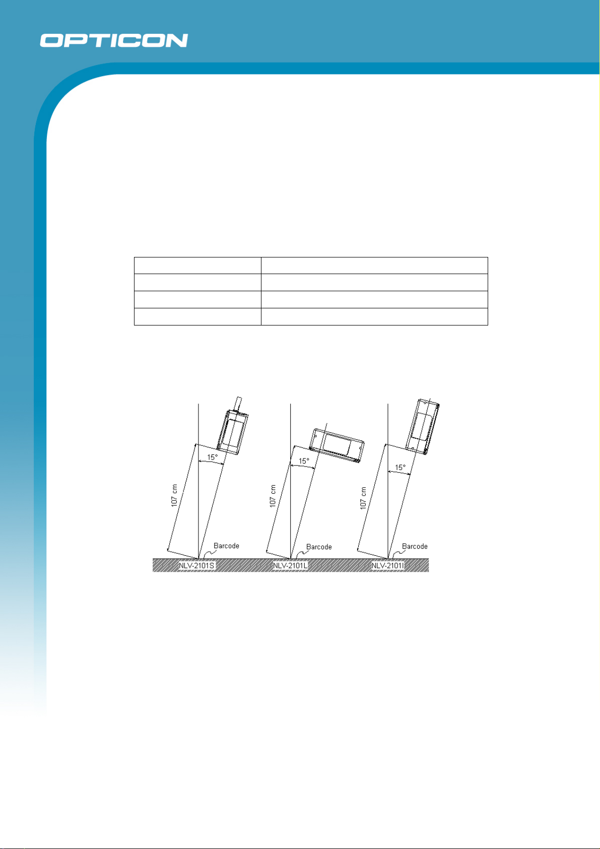
4.3. Ambient Light Immunity
Decoding performance is guaranteed when the range of illumination on a barcode
surface is between zero and the following values:
Incandescent light to 10,000 lx
Fluorescent light to 10,000 lx
Sunlight to 100,000 lx
Conditions
Barcode Sample: PDF417 with 0.254 mm resolution
Distance: 107 mm from the plastic mask of the camera module
Angle: α = 0° β = 15° γ = 0°
Curvature: R = ∞
Power Supply Voltage: 5.0 V
Opticon
NLV 2101
Scanning performance is guaranteed as long as direct light or a reflection from a light
source does not impact the light detection range of the NLV 2101.
Note: α, β and γ respectively represent pitch, skew and tilt. Please see section 6 for
how these values are defined.
Figure 1: Ambient light and scanning performance
9
Page 10
5. Electrical Specifications
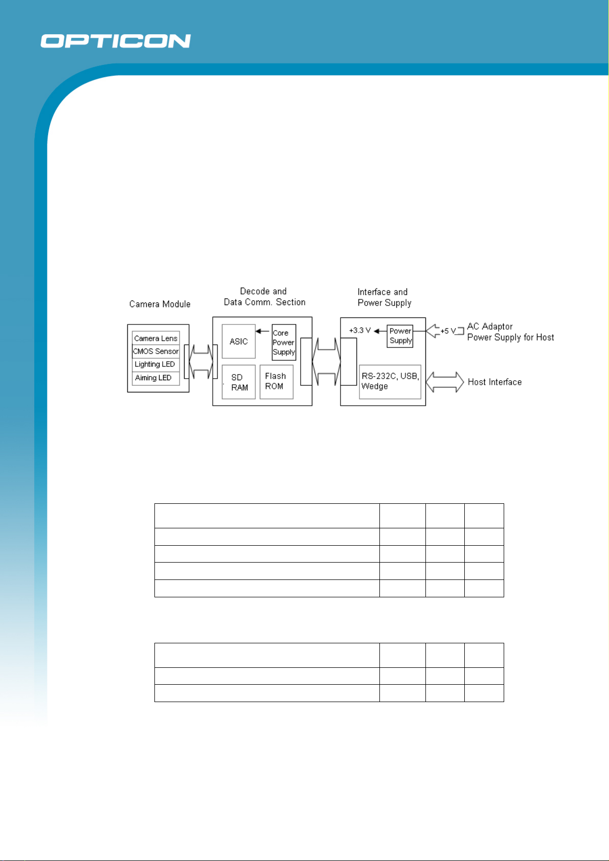
5.1. Framework and Structure
This product consists of a camera module, a decoder, communication controls, an
interface, and a power supply. The camera module consists of a CMOS area image
sensor and lens. The decoder decodes the scanned 1D and 2D codes. The interface
transfers data between this product and the host system.
• The NLV 2101 with RS-232C interface requires the supplied AC adaptor.
• The NLV 2101 with USB interface uses bus power. It does not require an AC
adaptor.
Opticon
NLV 2101
Specifications Manual
Figure 2: Framework and structure diagram
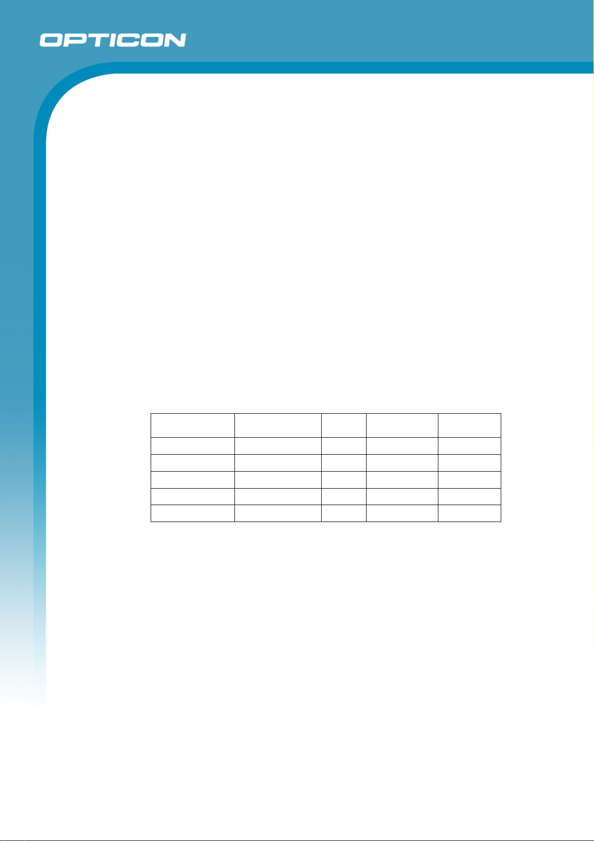
5.2. Electrical Characteristics
5.2.1. AC Adapter
AC adapter output: DC 5.0 V, 600 mA or less
Parameter Min Max Unit
Power Supply Voltage 5 V ± 10% 4.5 5.5 V
Ripple: 0.1 Vp-p or less, power supply voltage 5.0 V 10 100 kHz
Operating Current (typical) 230 330 mA
Stand-by Current (typical) 130 165 mA
5.2.2. USB Power Supply
Current consumption: 300 mA
Parameter Min Max Unit
Bus power class: high power (500 mA) - - mA
Ripple: 0.1 Vp-p or less, power supply voltage 5.0 V 10 100 kHz
10
Page 11

6. Optical Specifications
Parameter Specification Unit
Opticon
NLV 2101
Specifications Manual
Scan method CMOS area sensor
(black and white)
Scan rate 30 fps
Pixel count 1280 (H) x 1024 (V) pixel
Aiming LED wavelength (2 green LEDs) 527 nm
Lighting LED wavelength (4 red LEDs) 630 nm
View angle Horizontal: 47
Vertical: 37.5
-
°
11
Page 12
Specifications Manual
7. Technical Specifications
The conditions for technical specifications are as follows, unless otherwise specified in each
section.
Conditions
Ambient temperature and humidity: Room temperature (5 to 35º C)
Room humidity (45% to 85% RH)
Ambient light: 1000 to 1500 lx (on the surface of a barcode)
Light source: 3-wavelength inverter fluorescent light
Background: Barcode = black
Space = white
Margin = white
Background of label = black
Power supply voltage: 5.0 V
Successful scans: 70% and higher
Opticon
NLV 2101
7.1. Symbologies
The size of barcodes does not include quiet zones.
7.1.1.
Barcode
Resolution Symbology PCS Size (mm) Digits
0.508 mm Code 39 0.9 29 x 25 2
0.254 mm Code 39 0.9 14 x 10 2
0.127 mm Code 39 0.9 11 x 10 4
0.26 mm 13-digit JAN 0.9 25 x 19 13
0.26 mm 8-digit JAN 0.9 17.5 x 15.5 8
Barcode samples with 0.127 mm and 0.26 mm resolution are
OPTOELECTRONICS test samples. Other charts are printed by a regular printer.
N/W Ratio: 1:2.5
Angle: α = 0°, β = 15°, γ = 0°
Curvature R = ∞
12
Page 13

7.1.2. PDF417
Resolution Error Correction PCS Size (mm) Characters
0.339 mm Level-4 0.9 35 x 22 17
0.254 mm Level-4 0.9 26 x 16 17
0.127 mm Level-4 0.9 13 x 8 17
Charts are printed by a regular printer. Horizontal to vertical ratio is 3:1.
Opticon
NLV 2101
Specifications Manual
7.1.3.
7.1.4.
7.1.5.
QR Code (Model 2)
Resolution Error Correction PCS Size (mm) Characters
0.339 mm M 0.9 10 x 10 44
0.212 mm M 0.9 6 x 6 44
0.169 mm M 0.9 5 x 5 44
Charts are printed by a regular printer.
Data Matrix
Resolution Model PCS Size (mm) Characters
0.339 mm ECC200 0.9 8 x 8 40
0.212 mm ECC200 0.9 5 x 5 40
0.169 mm ECC200 0.9 4 x 4 40
Charts are printed by a regular printer.
Maxi Code
Resolution Model PCS Size (mm) Characters
0.889 mm Standard 0.9 26 x 26 29
Charts are printed by a regular printer.
7.2. Print Contrast Signal (PCS)
0.45 or higher (over 70% of reflectivity of space and quiet zone).
Reflectance of white bar-Reflectance of black bar
PCS=
Reflectance of white bar
Scanning performance may decline if dirt or scratches mar the optical window. Keep
the optical window clean.
7.3. Minimum Resolution
0.127 mm: Code39 and PDF417
0.169 mm: Data Matrix and QR Code
13
Page 14
Specifications Manual
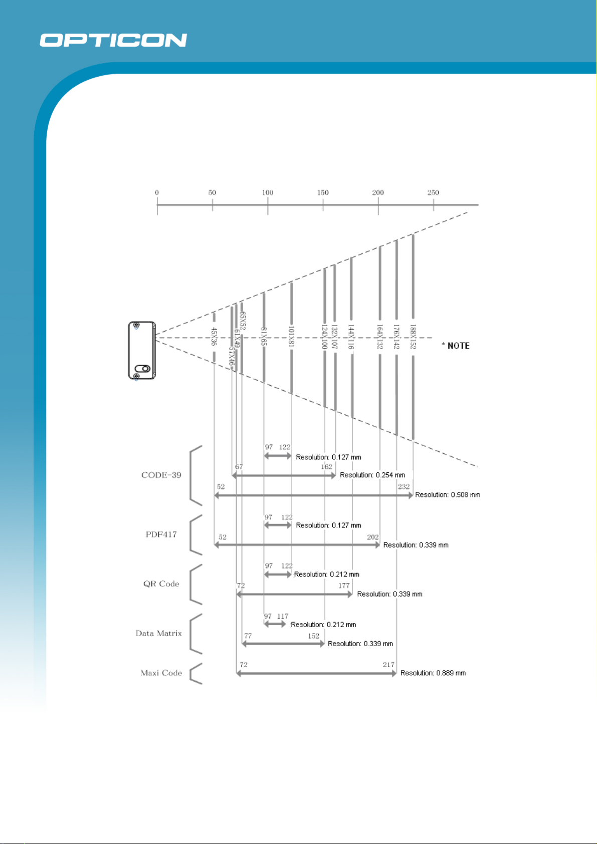
7.4. Scan Area and Resolution (L-type model)
The depth of field is measured from the plastic mask of the camera module. (The
distance from the camera module to the optical window is the same for all L-type, Stype and I-type models.) Depth of field is in millimeters. Values describe average
scannable ranges.
Opticon
NLV 2101
Figure 3: Scan area and resolution
14
Page 15

7.5. Pitch, Skew, and Tilt
7.5.1. Pitch Angle
α = ±50°
Opticon
NLV 2101
Specifications Manual
7.5.2.
7.5.3.
Skew Angle and Dead Zone
Skew angle: β = ±60° (Excluding dead zone)
Tilt Angle
γ = 360° or less
Figure 4: Pitch, skew, and tilt
Conditions
Barcode Sample: Code39 and PDF417 with 0.254 mm resolution
Distance: 107 mm from the plastic mask of the camera module
Angle: Curvature: R = ∞
(The calculation of pitch and tilt angles is based on the skew angle
formula being β = +15°)
Notes
When a barcode is printed on glossy paper or a card case, it may cause
difficulties in scanning due to the reflection of lighting LEDs. To improve scanning
performance under these circumstances, scan the barcode with a scan angle of
15 degrees or with lighting LEDs turned off. When scanning a barcode with
lighting LEDs turned off, confirm that there is enough ambient lighting in the room
(1000 lx or higher), or scanning performance may decline. Scanning performance
may also decline if room light reflects on the barcode surface.
15
Page 16

Specifications Manual
7.6. Curvature
With 8-digit JAN/UPC/EAN barcodes, decoding performance is guaranteed when
R ≥ 15 mm.
With 13-digit JAN/UPC/EAN barcodes, decoding performance is guaranteed when
R ≥ 20 mm.
Opticon
NLV 2101
Figure 5: Curvature
Conditions
Barcode Sample: JAN barcode
Distance: 107 mm from the mask of the camera module
Angle:
α = 0°, β =+15°, γ = 0°
16
Page 17

8. Aiming
8.1. Aiming Patterns
During a scan, the green LED patterns shown below will be visible. These patterns
assist you in aiming the imager; they are superimposed on the illuminated scan field.
The aiming patterns are only a guide. They do not indicate exact scannable width or
distance between a imager and a barcode.
Opticon
NLV 2101
Specifications Manual
Figure 6: Aiming patterns
8.2. Aiming Guidelines
• The focal point is where two central LED light patterns (green and square-shaped)
overlap—where two dots meet.
• To scan a barcode within the aiming range, make sure that two central LED light
patterns overlap, then place the center of the overlapping LED light patterns on
the center of the barcode.
• To scan a barcode wider than a width of the aiming range, aim at the barcode
from further away. Make sure that the barcode is between two LED light patterns
on both the right and left.
17
Page 18

9. Interface Specifications
9.1. RS-232C (9-pin) Interface Specifications
D-sub 9-pin output connector.
Opticon
NLV 2101
Specifications Manual
9.1.1.
9.1.2.
Settings and Communication
Reading the menu barcodes in section 11.1 can set the RS-232C interface
default.
Parameter [U2] setting
Baud rate 9600 bps
Start/stop bits 1 bit
Data bits 8 bits
Parity bits No parity
Handshaking No handshake
Flow control time out Indefinitely
Communication settings can be configured by scanning corresponding menu
barcodes.
Signal Level
Signal Name I/O RS-232C Level (V)
Mark/OFF Space/ON
TxD OUT -5 to -15 +5 to +15
RxD IN -3 to -15 +3 to +15
RTS OUT -5 to -15 +5 to +15
CTS IN -3 to -15 +3 to +15
9.1.3. Pin Assignment
Connector for imager side: D-sub 9-pin female
Pin No. Signal Name Rem arks
1 NC Open (not connected)
2 TxD
3 RxD
4 NC Connected to pin #6
5 GND
6 NC Connected to pin #4
7 CTS
8 RTS
9 NC Open (not connected)
Case FG Shield
Power supply: Power supply jack
18
Page 19

9.1.4. Interface Circuit
Opticon
NLV 2101
Specifications Manual
Figure 7: RS-232C interface circuit (9-pin)
9.1.5. Character Format
Figure 8:Character format (same for both sending and receiving)
9.1.6. Communication Format
Figure 9: Communication format
9.1.7. Handshaking
Select handshaking options using the menu or command listed below.
Handshaking Menu/Command
No handshake P0
BUSY/READY P1
MODEM P2
ACK/NAK P3
ACK/NAK NO RESPONSE P4
19
Page 20

Specifications Manual
a) No Handshaking
The imager attempts the communication regardless of the state of the host
system.
Figure 10: No handshaking
b) BUSY/READY
The imager and the host computer notify each other of their state and
whether they can receive data with BUSY/READY through an RTS line.
They can communicate state to each other through a CTS line when
connected as in the following figure.
Opticon
NLV 2101
Figure 11: Busy/Ready communication
The imager stays ON (is able to receive data) except during certain parts
of the process, such as receiving data (buzzer command execution),
transmitting data, and menu processing. The imager checks the CTS line
before transmitting data. When it is ON, the imager transmits data. When it
is OFF, the imager waits for it to turn ON within a set time. The imager will
abort transmission with an error indication (buzzer) when the CTS line is
not ON within a specified period. The Flow Control time-outs are as
follows, and the default setting is “indefinitely“ (I0).
Flow Control Time Out Menu/Command
Indefinitely I0
100 ms I1
200 ms I2
400 ms I3
20
Page 21

Opticon
NLV 2101
Specifications Manual
Figure 12: Cannot receive command
CTS, TxD signal timing
When the CTS line is turned OFF while sending a TxD signal, the imager
transmits one character and waits. When the RTS signal is turned ON while
transmitting a character, the character will be transmitted.
Figure 13: Signal timing
Note: When using loopback (wire connection) for CTS, RTS line of the imager in this
setting, No handshake is not enabled.
c) MODEM
The imager turns CS line ON before transmitting data. Other processes
are the same as BUSY/READY.
Figure 14: Modem transmit data
21
Page 22

Specifications Manual
d) ACK/NAK
After data has been transmitted, the imager expects to receive one of the
following responses from the host:
• ACK response—Action: The imager completes transmission with the
good-read buzzer and returns to the initial state.
• NAK response—Action: The imager sends the data again and waits for
the response from the host.
• DC1 response—Action: The imager returns to waiting for the trigger, if
it has a trigger (the initial state).
• None response—Action: The imager sounds the error buzzer and
returns to the initial state.
ACK/NAK timeout can be set as follows using the menu or commands.
ACK/NAK timeout Menu / Command
Opticon
NLV 2101
Indefinitely (default)
100 ms
500 ms
1000 ms
XI4
XI5
XI6
XI7
Figure 15: ACK/NAK
22
Page 23

Specifications Manual
e) ACK/NAK NO RESPONSE
When no response from the host is received within the setting time, the
imager assumes an ACK response, and returns to the initial state without
the error buzzer. The other actions are the same as ACK/NAK.
Opticon
NLV 2101
Figure 16: ACK/NAK—No response
9.2. RS-232C (10-pin) Interface Specifications
Cut-off cables for host system.
All RS-232C signals except for sequencer signals should be in accordance with
section 9.1.
9.2.1.
Signal Level
The following table provides information applicable only to the sequencer
signals.
Signal Name IN/OUT RS-232C Level (V)
L-level H-level
Trigger IN -0.3 V to 0.6 V 3 V to Vcc + 0.3 V
OK OUT 0.4 V / 10 mA OC output / max. 6 V
NG OUT 0.4 V / 10 mA OC output / max. 6 V
23
Page 24

9.2.2. Signal Name and Wire Color
Wire Color Signal Name Note
Brown Trigger (Enable: Low / Disable: Hi)
Orange NG
Yellow OK
Green TxD
Blue RTS
White RxD
Gray CTS
Red VCC +5 V
Black GND Signal GND
Black Flexible Tube FG Shield
Opticon
NLV 2101
Specifications Manual
9.2.3. Interface Circuit
Figure 17: RS-232C interface circuit (10-pin)
24
Page 25

9.2.4. OK/NG Signal Output Timing
The following describes the output timing of OK/NG signals. The signals are
output through the open connector of an NPN transistor.
a) Good Read (One Shot)
Opticon
NLV 2101
Specifications Manual
Figure 18: Sequencer signal 1
b) Read Error within Specified Time (One Shot)
Figure 19: Sequencer signal 2
25
Page 26

c) Good Read (Synchronous)
Figure 20: Sequencer signal 3
d) When Reading Unregistered Barcodes
Opticon
NLV 2101
Specifications Manual
Figure 21: Sequencer signal 4
26
Page 27

Specifications Manual
e) Sequencer Output Commands and Menus
UM OPTO Menu Function/Feature Menu Command
Opticon
NLV 2101
X8A 8A External trigger input signal (active H)
X8B 8B External trigger input signal (active L)
X*C 8C SYNC synchronous H active
X*D 8D SYNC synchronous H active
X*D 8E One Shot H active
X*F 8F One Shot L active
X*G 8G One Shot time 10 ms
X*H 8H One Shot time 20 ms
X*I 8I One Shot time 30 ms
X*J 8J One Shot time 40 ms
X*K 8K One Shot time 50 ms
X*L 8L One Shot time 60 ms
X*M 8M One Shot time 70 ms
X*N 8N One Shot time 80 ms
X*O 8O One Shot time 90 ms
X*P 8P One Shot time 100 ms
X*Q 8Q Enable sequence output
X*R 8R Disable sequence output
To set menus with “U”, send “Z2” after a command.
U
U
U
U
U
U
27
Page 28

9.3. USB Interface Specifications
Use full-speed USB interface for both USB-HID and USB-VCP.
For the USB-VCP interface, a driver needs to be installed on the host.
Opticon
NLV 2101
Specifications Manual
9.3.1.
Settings
USB-HID: Scan menu barcodes “ZZ” + “SU” + “ZZ”.
USB-VCP: Scan menu barcodes “ZZ” + “C01” + “ZZ”.
9.3.2.
Connector Specifications
USB A Connector
Figure 22: USB A interface connector
Contact Number Signal Name
1 VCC
2 -Data
3 +Data
4 GND
28
Page 29

9.3.3. USB Interface Circuit
Opticon
NLV 2101
Specifications Manual
Figure 23: USB interface circuit
Note: Do not use the host keyboard during data transmission when
the imager is connected as USB-HID or if the capture application
cannot distinguish between the imager and a standard keyboard.
10. Cable and Connector
10.1. RS-232C (9-pin) Cable (standard specification)
Type: Straight
Diameter: Φ3.8±0.5 mm
Length: 1500 (+100, -0) mm
Cores: 9 insulated wires, 1 conductive wire
Weight: Approximately 65 g
Figure 24: RS-232C (9-pin) cable
29
Page 30

10.2. RS-232C (10-pin) Cable (standard specification)
Type: Straight
Diameter: Φ3.8±0.5 mm
Length: 1500 (+100, -0) mm
Cores: 9 insulated wires, 1 conductive wire (excluding USB interface cable)
Weight: Approximately 65 g
Opticon
NLV 2101
Specifications Manual
Figure 25: RS-232C (10-pin) cable
10.3. USB Cable (standard specification)
Type: Straight
Diameter: Φ3.8 ± 0.5 mm
Length: 1500 +100, -0 mm
Cores: 4 insulated wires, 1 conductive wire (excluding USB interface cable)
Weight: Approximately 50 g
Figure 26: USB cable
30
Page 31

10.4. Imager Connector Specifications
Signal Name
Pin Number
RS-232C (9P) RS-232C (10P) USB
Opticon
NLV 2101
Specifications Manual
1
2
3
4
5
6
7
8
9
10
11
12
N.C N.C N.C
N.C N.C N.C
N.C Trigger N.C
N.C OK N.C
N.C NG N.C
GND GND N.C
RTS RTS N.C
CTS CTS N.C
TxD TxD N.C
RxD RxD N.C
N.C N.C USB-
N.C N.C USB+
Connector used: SHR-12V-S manufactured by JST Mfg. Co., Ltd.
CN3 (2-pin) for power input
Specifications
Pin Number
RS-232C (9P) RS-232C (10 P ) USB
1
2
+5V +5V +5V
GND GND GND
31
Page 32

11. Default Settings
11.1. Set Default Interface
Scan the following menu barcodes to return to the default settings.
RS-232C
Functions Menu labels Menu codes
Opticon
NLV 2101
Specifications Manual
SET
RS-232C
END
USB-HID
Functions Menu labels Menu codes
SET
USB-HID
END
USB-VCP
Functions Menu labels Menu codes
SET
_ZZ_
_U2_
_ZZ_
_ZZ_
_SU_
_ZZ_
_ZZ_
ZZ
U2
ZZ
ZZ
SU
ZZ
ZZ
USB-VCP
END
_C0_
_ZZ_
C01
ZZ
32
Page 33

11.2. Default Settings 1: Readable Codes
Opticon
NLV 2101
Specifications Manual
Code type Reading Transmit
UPC-A
UPC-A Add-on
UPC-E
UPC-E1
EAN-13
EAN-13 Add-on
EAN-8
EAN-8 Add-on
Aztec Code
Aztec Runes
Chinese Post
Code 39
Code 93
Code 128
Composite EAN
EAN-13 CCA
EAN-13 CCB
EAN-8 CCA
EAN-8 CCB
Composite UPC
UPC-A CCA
UPC-A CCB
UPC-E CCA
UPC-E CCB
Composite RSS
RSS-14 CCA / RSS-14 CCB /
RSS Limited CCA / RSS Limited
CCB / RSS Expanded CCA /
RSS Expanded CCB
Composite UCC
GS1-128 (EAN-128) UCC
GS1-128 (EAN-128) CCA
GS1-128 (UCC/EAN-128) CCB
GS1-128 (UCC/EAN-128) CCC
Data Matrix (ECC200)
Data Matrix (ECC0-140)
IATA
Industrial 2of5
Interleaved 2of5
Korean Post Authority Code
Code
Transmit
CD
Calculate
Length
X X
X X
X X
X X
X X —
X X
X X
X X
X X
X X
X X —
X X X
X
X
X
X
X —
X
X —
X —
X —
X
X
X
(Linear
1D)
(Linear
1D)
(Linear
1D)
—
CD
X
X
X
X
X
Transmit
Other
Not transmit
ST/SP
33
Page 34

Opticon
NLV 2101
Specifications Manual
Code type Reading Transmit
Matrix 2of5
Maxi Code (Mode 2–5)
MicroPDF417
Micro QR Code
NW-7 Codabar
PDF417
MSI/Plessey
UK/Plessey
QR Code
GS1 Databar (RSS-14 Standard)
Truncated
Stacked
Stacked Omni-directional
GS1 Databar (RSS Expanded)
Standard
Stacked
GS1 Databar (RSS Limited)
S-Code
Telepen
Tri-Optic
Transmit
Code
Length
X X
X —
X —
X —
X
X —
X
X
X —
X
X X
X
X
X X
X — —
Calculate
CD
CD
X
X
X
Transmit
Other
Not transmit
ST/SP
Not transmit
ST/SP
Notes:
In the “Reading” column, “
” means “Enable reading” and “X” means “Disable
reading.”
In the “Transmit code length” column, “
” means “Transmit code length” and “X”
means “Do not transmit code length.”
In the “Transmit CD” column, “
” means “Transmit check digit” and “X” means “Do not
transmit check digit.”
In the “Calculate CD” column, “
” means “Calculate check digit” and “X” means “Do
not calculate check digit.”
“— “ means “not supported.”
In the “Prefix” column, “—“ means “there is no prefix setting.”
34
Page 35

11.3. Default Settings 2: Read Options, Trigger, Buzzer
Item Default Setting
Setting the number of characters Fixed length OFF all codes
Read mode Multiple read
Multiple read reset time 500 ms
Add-on wait mode 500 ms
Multiple label read Disable
Multiple column read Disable
Default option
([X0] setting)
Other options
([X1 .. X3] setting)
([BS .. BW] setting)
Trigger switch Enable
Read time 2 seconds
Buzzer duration 50 ms
Buzzer tone Single tone (3 kHz)
Buzzer loudness Maximum
Good read LED Indicator duration 200 ms
Read 4 times, redundancy = 3 Redundancy
Read n times, redundancy = n+1 for the following
symbologies and lengths:
● Code 11 with length <= 5
● Code 39 with length <= 5
● IATA,Industrial 2of5, Interleaved 2of5 with length <= 8
● Matrix 2of5 (& Chinese Post), Scode with length <= 8
● MSI/Plessey with length <= 4
● NW-7 (Codabar) with all lengths
Opticon
NLV 2101
Specifications Manual
11.4. Default Settings 3A: Serial Communication Settings—RS-232C, USB-VCP
Parameter “U2” and “C01” Default Setting
ACK/NAK No handshaking
Flow Control time out Indefinitely
ACK/NAK timeout 100 ms
Command header ESC/STX
Command terminator CR/ETX
ACK/NAK for RS-232C comm. Disable
35
Page 36

12. Serial Number
The serial number shown below is affixed to the imager.
Opticon
NLV 2101
Specifications Manual
クラス1 LED製品
JI S C6802: 2005
CLASS 1 L ED PRODUCT IEC60825-1+A2:2001
OPTOEL ECTRONI CS CO.,LTD.
WARABI - SHI , SAI T AMA
Figure 27: Serial number diagram
MADE I N J APAN
36
Page 37

13. Packaging Specifications
13.1. Individual Packaging Specification
Put the imager in a protective foam bag and place it in an individual packing box.
Package dimensions (assembled): 245 mm (W) x 110 mm (D) x 38 mm (H)
Opticon
NLV 2101
Specifications Manual
Figure 28: Individual packaging
37
Page 38

13.2. Collective Packaging Specification
Opticon
NLV 2101
Specifications Manual
Figure 29: Collective packaging
Note: The “RO” mark labeled on the package tray or package box guarantees that the
applicable product has passed our test of RoHS restrictions compliance (the
restriction of the use of certain hazardous substances in electrical and electronic
equipment, 2002/95 EC). However, this document does not have any legal weight in
the European Union.
38
Page 39

14. Durability
14.1. Electrical Noise
No malfunction occurred when sinusoidal electrical noise (50 Hz–100 kHz, < 0.1 Vpp) was added to the power supply line.
Conditions
Barcode Sample: OPTOELECTRONICS Test Sample
PCS 0.9
Resolution 0.25 mm
Symbology 9-digit Code 39
Quiet Zone 10 mm
N/W Ratio 1:2.5
Distance 150 mm
Angle α = 0° β = 15° γ = 0°
Curvature R = ∞
Power Supply Voltage 5.0 V
Opticon
NLV 2101
Specifications Manual
14.2. Static Electricity
Air discharge: ±8 kV max. (No malfunction)
Contact discharge: ±4 kV max. (No malfunction)
Measurement
environment:
Discharge resistance: 330 Ω
Capacitor charging: 150 pF
±15 kV max. (No destruction)
±15 kV max. (No destruction)
Use electrostatic testing device compliant with IEC 61000-4-2
39
Page 40

14.3. Shock
14.3.1. Drop Test (without packaging)
No malfunction occurred after the following drop test.
Shock Test: Drop the imager from 75 cm onto a concrete floor once on each of
its six sides.
Opticon
NLV 2101
Specifications Manual
Figure 30: Detailed view of drop test
14.3.2. Drop Test (with individual packaging)
No malfunction occurred after the following drop test.
Shock Test: Drop the individually packaged imager from 100 cm onto a
concrete floor once on its one corner, three edges, and six sides (ten drop
tests, total).
14.4. Vibration Strength
No malfunction occurred after the following vibration test.
Vibration Test: Increase the frequency of the vibration from 12 Hz to 100 Hz with
accelerated velocity 19.6 m/s
2
(2G) for six minutes in an operating state. Repeat this
routine in X, Y, and Z directions ten times.
14.5. Dust and Drip Proof
IEC IP67
14.6. Cable Strength
No malfunction to the cable’s performance occurred after the following pulling test.
Pulling test: Secure the imager and pull the cable with the force of 2.5 kg for 1
second. Repeat 20 times.
40
Page 41

Specifications Manual
14.7. Cable Bending Test
No malfunction to the cable’s performance occurred after the following bending test.
Bending test: Fix the imager and attach a weight of 500 grams and swing the cable
back and forth at an angle of 60 degrees. Repeat 1,000 times.
Figure 31: Cable tail bending test
Opticon
NLV 2101
15. Reliability
MTBF (Mean Time Between Failures) of this product is 50,000 hours.
The estimate of MTBF and product life cycle is based on standard operation of the product
within the recommended temperature range and without extreme electronic or mechanical
shock.
41
Page 42

16. Regulatory Compliance
16.1. LED Safety
All LED-based products are LED class 1 and are safe under reasonably foreseeable
operating conditions. Do not stare into the beam.
• JIS C6802: 2005: Class 1
• IEC 60825-1+A2: 2001 Class 1
16.2. Product Safety
EN60950-1: 2001
IEC60950-1: 2001
16.3. EMC
CE
VCCI Class B: This is a Class B product, to be used in a domestic environment based
on the Technical Requirement of the Voluntary Control Council for Interference from
Information Technology Equipment (VCCI). If this is used near a radio or television
receiver in a domestic environment, it may cause radio interference. Please install
and use the equipment according to the instruction manual.
Opticon
NLV 2101
Specifications Manual
FCC Part 15 Subpart B Class B: This device complies with part 15 of the FCC Rules.
Operation is subject to the following two conditions: (1) this device may not cause
harmful interference, and (2) this device must accept any interference received,
including interference that may cause undesired operation.
16.4. RoHS
RoHS: The restriction of the use of certain hazardous substances in electrical and
electronic equipment, 2002/95 EC.
42
Page 43

17. Safety
Handle this product carefully. Do not deliberately subject it to any of the following.
17.1. Shock
Do not throw or drop the imager.
Do not place heavy objects on the cables.
17.2. Temperature Conditions
Do not use the imager at temperatures outside the specified range.
Do not pour boiling water on the imager.
Do not throw the imager into the fire.
Do not forcibly bend the cables at low temperatures.
17.3. Foreign Materials
Do not immerse the imager in liquids.
Opticon
NLV 2101
Specifications Manual
Do not subject the imager to chemicals.
17.4. Other
Do not plug/unplug the connectors before disconnecting the power.
Do not disassemble this product.
Do not place the product near a radio or a TV receiver, as the imager may cause
reception problems.
The imager may be damaged by voltage drops.
The imager may not perform properly in environments when placed near a flickering
light, such as a computer monitor, television, etc.
43
Page 44

18. Mechanical Drawing
Opticon
NLV 2101
Specifications Manual
Figure 32: Mechanical drawing (Type-L)
Note: Figure 32 shows the NLV 2101 Type-L. There are two other available types, Type-I
(shown in Figure 33) and Type-S (shown in Figure 34), each with different positioning of the
optical window. The default model type is the Type-L; the Type-I and Type-S are available
for large purchase orders.
44
Page 45

Opticon
NLV 2101
Specifications Manual
Figure 33: Mechanical drawing (Type-I)
Figure 34: Mechanical drawing (Type-S)
45
 Loading...