

Page 1
Undecoded Laser Scan Engine
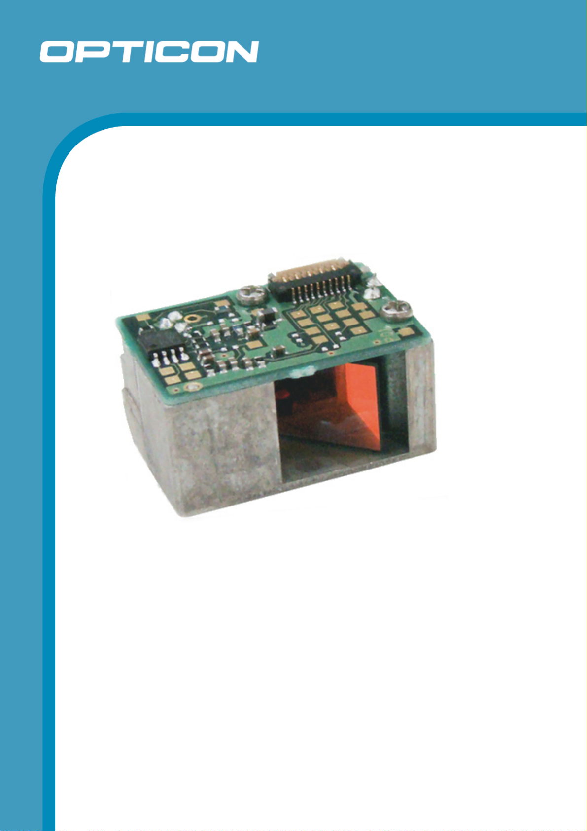
MSL 2000
The MSL 2000 is an undecoded compact laser bar
code scan engine that can be installed in various
handheld products.
Specifications Manual
Page 2

All information subject to change without notice.
Document History
Opticon
MSL 2000
Specifications Manual
Model Number:
Edition:
Date:
MSL 2000
1
2006-08-01
Specification Number:
Original Spec Number:
SS06026
SS05045
Copyright 2008 Opticon. All rights reserved.
This manual may not, in whole or in part, be copied, photocopied, reproduced, translated or converted to any
electronic or machine readable form without prior written consent of Opticon.
Limited Warranty and Disclaimers
PLEASE READ THIS MANUAL CAREFULLY BEFORE INSTALLING OR USING THE
PRODUCT.
Serial Number
A serial number appears on all Opticon products. This official registration number is directly related to the device
purchased. Do not remove the serial number from your Opticon device. Removing the serial number voids the
warranty.
Warranty
Unless otherwise agreed in a written contract, all Opticon products are warranted against defects in materials and
workmanship for two years after purchase. Opticon will repair or, at its option, replace products that are defective in
materials or workmanship with proper use during the warranty period. Opticon is not liable for damages caused by
modifications made by a customer. In such cases, standard repair charges will apply. If a product is returned under
warranty and no defect is found, standard repair charges will apply. Opticon assumes no liability for any direct, indirect,
consequential or incidental damages arising out of use or inability to use both the hardware and software, even if
Opticon has been informed about the possibility of such damages.
Packaging
The packing materials are recyclable. We recommend that you save all packing material to use should you need to
transport your scan engine or send it for service. Damage caused by improper packaging during shipment is not
covered by the warranty.
Trademarks
Trademarks used are the property of their respective owners.
Opticon Inc. and Opticon Sensors Europe B.V. are wholly owned subsidiaries of OPTOELECTRONICS Co., Ltd., 1217, Tsukagoshi 4-chome, Warabi-shi, Saitama, Japan 335-0002. TEL +81-(0) 48-446-1183; FAX +81-(0) 48-446-1184
SUPPORT
USA Europe
Phone: 800-636-0090
Email: support@opticonusa.com Email: support@opticon.com
Web: www.opticonusa.com Web: www.opticon.com
2
Page 3

Opticon
MSL 2000
Specifications Manual
Contents
1. Abstract....................................................................................................................................... 5
2. Overview...................................................................................................................................... 5
3. Physical Features....................................................................................................................... 5
3.1. Dimensions ......................................................................................................................... 5
3.2. Weight ................................................................................................................................. 5
4. Environmental Specifications ...................................................................................................6
4.1. Operating Temperature and Humidity................................................................................. 6
4.2. Storage Temperature and Humidity .................................................................................... 6
4.3. Ambient Light Immunity....................................................................................................... 6
5. Electrical Specifications ............................................................................................................ 7
5.1. Absolute Maximum Ratings ................................................................................................ 7
5.2. Electrical Characteristics..................................................................................................... 7
6. Optical Specifications................................................................................................................ 9
6.1. Laser Scan Specifications................................................................................................... 9
6.1.1. Tilt of Laser Scan Line ...............................................................................................................9
6.1.2. Curvature of Scanning ............................................................................................................... 9
7. Technical Specifications.......................................................................................................... 10
7.1. Print Contrast Signal (PCS) .............................................................................................. 10
7.2. Minimum Resolution.......................................................................................................... 10
7.3. Scan Area and Resolution ................................................................................................ 11
7.3.1. Depth of Field...........................................................................................................................11
7.4. Pitch, Skew, and Tilt.......................................................................................................... 13
7.4.1. Pitch Angle ...............................................................................................................................13
7.4.2. Skew Angle and Dead Zone ....................................................................................................13
7.4.3. Tilt Angle ..................................................................................................................................13
7.5. Curvature .......................................................................................................................... 14
8. Interface Specifications ...........................................................................................................15
8.1. Interface Connector........................................................................................................... 15
8.1.1. Filter Mode Settings .................................................................................................................16
8.1.2. Comparison of Scanning Performance with Different Filter Modes.........................................17
8.2. Interface Circuit ................................................................................................................. 19
8.3. Timing Waveform .............................................................................................................. 21
8.4. Laser Light Specifications ................................................................................................. 22
9. Serial Number ........................................................................................................................... 23
10. Packaging Specifications........................................................................................................24
3
Page 4

Opticon
MSL 2000
Specifications Manual
10.1. Collective Packaging Specification ................................................................................... 24
11. Durability................................................................................................................................... 25
11.1. Electrical Noise ................................................................................................................. 25
11.2. Shock ................................................................................................................................ 25
11.2.1. Drop Test (without packaging) .................................................................................................25
11.3. Vibration Strength ............................................................................................................. 25
12. Reliability................................................................................................................................... 25
13. Regulatory Compliance ...........................................................................................................26
13.1. Laser Safety ...................................................................................................................... 26
13.2. RoHS................................................................................................................................. 26
14. Safety......................................................................................................................................... 26
14.1. Shock ................................................................................................................................ 26
14.2. Temperature Conditions.................................................................................................... 26
14.3. Foreign Materials .............................................................................................................. 26
14.4. Other ................................................................................................................................. 26
15. Mechanical Drawing................................................................................................................. 27
Table of Figures
Figure 1. Current waveform.......................................................................................................... 8
Figure 2: Curvature....................................................................................................................... 9
Figure 3: Depth of field ................................................................................................................11
Figure 4: Pitch, skew, and tilt ...................................................................................................... 13
Figure 5: Curvature..................................................................................................................... 14
Figure 6: Standard barcode scanning performance.................................................................... 17
Figure 7: Modulation scanning performance .............................................................................. 18
Figure 8: Low PCS scanning performance................................................................................. 18
Figure 9: Timing waveform ......................................................................................................... 21
Figure 10: Laser light specifications ...........................................................................................22
Figure 11: Serial number diagram .............................................................................................. 23
Figure 12: Individual packaging.................................................................................................. 24
Figure 13: Mechanical drawing...................................................................................................27
4
Page 5

Specifications Manual
1. Abstract
This document provides specifications of the MSL 2000 laser scan engine.
2. Overview
The MSL 2000 (hereafter called “the scan engine”) is an undecoded compact laser barcode
scan engine that can be installed in various handheld products such as portable terminals.
When scanning a target at the minimum decode distance, this scan engine can scan up to
44 mm wide at an angle of 44°. The use of a short-wavelength red laser beam enhances
the visibility of the laser beam when scanning barcodes.
This scan engine scans barcodes using laser light and outputs those barcode images as a
logic level signal (hereinafter called the “signal”). This scan engine also outputs timing
waveforms (signals) synchronized with scanning. Such timing waveforms (signals) are
hereinafter referred to as “TIMING”. This scan engine can be turned on and off via an
external input signal, “POWER EN”. The laser light emission of this scan engine can be
controlled via an external input signal, “LASER EN”.
Opticon
MSL 2000
This scan engine is compliant with RoHS.
3. Physical Features
3.1. Dimensions
W 20.4 x D 14.0 x H 11.0 mm
3.2. Weight
3.9 g (max.)
5
Page 6

4. Environmental Specifications
4.1. Operating Temperature and Humidity
Temperature: -20 to 65° C
Humidity: 5 to 90% RH
4.2. Storage Temperature and Humidity
Temperature: -30 to 70° C
Humidity: 5 to 90% RH
4.3. Ambient Light Immunity
Decoding performance is guaranteed when the range of illumination on a barcode
surface is between zero and the following values:
Incandescent light 4,000 lx
Fluorescent light 4,000 lx
Sunlight 80,000 lx
Opticon
MSL 2000
Specifications Manual
Conditions
Barcode Sample: OPTOELECTRONICS Test Sample
PCS: 0.9
Resolution: 0.25 mm
Symbology: 9-digit Code 39
Quiet zone: 10 mm
N/W ratio: 1:2.5
Distance: 150 mm from the exit window
Angle (see note below): α = 0° β = 15° γ = 0°
Curvature: R = ∞
Power supply voltage: 3.3 V
Direct light or specular reflection from a light source should be prevented from
entering the acceptance area.
Note: α, β and γ respectively represent pitch, skew and tilt. Please see section 6.1.1
for how these values are defined.
6
Page 7
5. Electrical Specifications
5.1. Absolute Maximum Ratings
Parameter Symbol Value Unit
Power Supply Voltage (Vcc to GND) VCC 6.0 V
Input Voltage VI -0.3 to
5.2. Electrical Characteristics
Vcc = 3.3V, Ta = 25° C
Parameter Symbol Conditions Min Typical Max Unit
Opticon
MSL 2000
Specifications Manual
V
V
+0.3
CC
Power Supply Voltage
Operating Current 1
Operating Current 2
Rush Current Peak
Standby Current
Stop Current
H-level
Input Voltage
L-level
H-level
Output Voltage
L-level
Input Current
3.0 - 3.6 V
V
CC
I
OP1
I
OP2
I
PEEK
I
STAN
I
STOP
V
V
V
OH
V
OL
Vcc = 3.3V, Ta = 25° C
Vcc = 3.3V, Ta = 65° C
Vcc = 3.3V, Ta = 25° C
Vcc = 3.3V, Ta = 65° C
With Vcc Applied
POWER EN = ON,
LASER EN = OFF
POWER EN=OFF
IH
IL
V
- - 0.5 V
IOH<1mA
IOL<1mA
- 35 45 mA
- 45 55 mA
- 55 65 mA
- 65 75 mA
- 250 500 mA
- 35 45 mA
- - 1 μA
-0.5 - - V
CC
-0.3 - - V
V
CC
- - 0.3 V
VIN=3.3V - - -50 μA
I
IN
VIN=0V - - 10 μA
7
Page 8
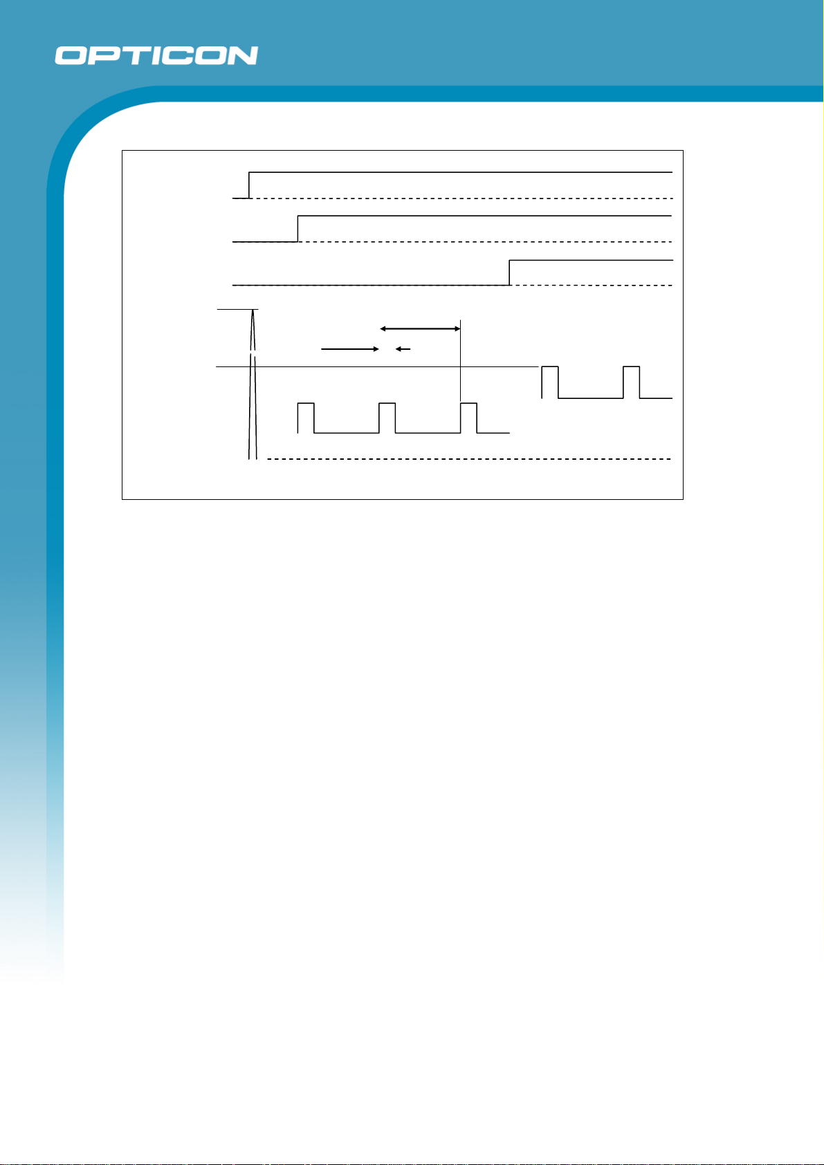
Vcc
POWER EN
LASER EN
Ipeek
Iop2
Iop1
Istan
Opticon
MSL 2000
Specifications Manual
ON
OFF
ON
OFF
ON
OFF
8.33 ~ 12.5ms
2.5ms Max
500μs Max
Current Waveform
Figure 1. Current waveform
8
Page 9
6. Optical Specifications
6.1. Laser Scan Specifications
Parameter Specification Unit
Light-emitting element Red laser diode —
Emission wavelength 650 ±10 (25° C) nm
Light output 1.0 or less mW
Scanning method Bi-directional scanning —
Scanning speed 100 ±20 scans/s
6.1.1. Tilt of Laser Scan Line
(The maximum tilt in between both ends of the scan line.)
• Less than 1.2 degrees upward tilt from the scan origin (MM mirror).
Opticon
MSL 2000
Specifications Manual
Scan angle: 54 ±5 ° Scan angle
Read angle: 44 (Min) °
• Maximum of 3.1 millimeters when measured at the point 150
millimeters away from the scan origin.
(The measurement is taken at the center of the scan line.)
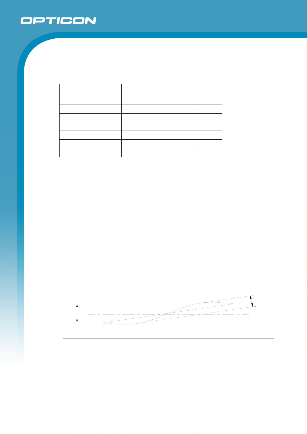
6.1.2.
Curvature of Scanning
(The maximum gap between the straight line connecting both ends of the laser
scan line and the actual laser scan line.)
• Less than 1.27 degrees curvature from the scan origin.
• Maximum of 3.3 millimeters when measured at the point 150
millimeters away from the scan origin.
(The measurement is taken at the center of the scan line.)
C
u
r
v
a
t
u
r
e
t
l
i
T
Figure 2: Curvature
Horizontal Line
9
Page 10

Specifications Manual
7. Technical Specifications
The conditions for technical specifications are as follows, unless otherwise specified in each
section.
Conditions
Ambient temperature and humidity: Room temperature (5 to 35º C)
Room humidity (45% to 85% RH)
Ambient light: 500 to 900 lx
Background: Barcode = black
Space = white
Margin = white
Background of label = black
Power supply voltage: 3.3 V
Decoding test: Over 95% decode
Opticon
MSL 2000
7.1. Print Contrast Signal (PCS)
0.45 or higher (over 70% of reflectivity of space and quiet zone).
Reflectance of white bar-Reflectance of black bar
PCS=
Reflectance of white bar
Scanning performance may decline if dirt or scratches mar the optical window. Keep
the optical window clean.
7.2. Minimum Resolution
0.127 mm
10
Page 11

7.3. Scan Area and Resolution
7.3.1. Depth of Field
The depth of field is measured from the edge of the exit window. The decode
area is rectilinear near the exit window and expands in an arc centered on a
virtual reference point in the distance.
Resolution
0.127
60 - 110
Opticon
MSL 2000
Specifications Manual
0.15
0.25
0.5
1.0
50 - 130
50 - 230
50 - 380
70 - 550
(in millimeters)
Figure 3: Depth of field
PCS Resolution
(mm)
0.9 1.0 70–550
0.9 0.5 50–380
0.9 0.25 50–230
0.9 0.15 50–130
0.9 0.127 60–110
Decode Depth (mm)
11
Page 12

Conditions
Opticon
MSL 2000
Specifications Manual
Filter Selection: Standard Mode
Details: The depth of field is measured from the edge of the exit window.
The decode area is rectilinear near the exit window and expands in an arc
centered on a virtual reference point in the distance.
Barcode Sample: OPTOELECTRONICS Test Sample
N/W ratio: 1:2.5
Angle: α = 0°, β = 15°, γ = 0°
Curvature: R = ∞
Resolution (mm) Symbology PCS Quiet Zone Digits
1.0 Code 39 0.9 25 mm 1
0.5 Code 39 0.9 18 mm 3
0.25 Code 39 0.9 10 mm 8
0.15 Code 39 0.9 7 mm 10
0.127 Code 39 0.9 5 mm 4
12
Page 13

7.4. Pitch, Skew, and Tilt
7.4.1. Pitch Angle
α = ±35°
Opticon
MSL 2000
Specifications Manual
7.4.2.
7.4.3.
Skew Angle and Dead Zone
Skew angle: β = ±50° (Excluding dead zone)
Dead zone: β = ±8° (There are some areas in which decoding fails due to
specular reflection)
Tilt Angle
γ = ±20°
Figure 4: Pitch, skew, and tilt
Conditions
Barcode Sample: OPTOELECTRONICS Test Sample
Distance: 110 mm from the exit window
Label:
Angle: Curvature: R = ∞, Skew Angle = β +15° (for measuring Pitch Angle and Tilt Angle)
Pitch, Skew Angle, Dead Zone
PCS = 0.9, Resolution = 0.25 mm, Symbology = 9-digit Code 39,
Quiet Zone = 10 mm, N/W Ratio = 1:2.5
Tilt Angle
PCS = 0.9, Resolution = 0.26 mm, Symbology = 13-digit JAN, Quiet Zone = 10 mm
13
Page 14

Specifications Manual
7.5. Curvature
With 8-digit JAN/UPC/EAN barcodes, decoding performance is guaranteed when
R≥15 mm.
With 13-digit JAN/UPC/EAN barcodes, decoding performance is guaranteed when
R≥20 mm.
Opticon
MSL 2000
Figure 5: Curvature
Conditions
Barcode Sample: OPTOELECTRONICS Test Sample
Distance: 110 mm from the exit window
Label: PCS = 0.9, Resolution = 0.26 mm, Quiet Zone = 10 mm
Angle: Skew Angle β = +15°
14
Page 15

8. Interface Specifications
8.1. Interface Connector
Opticon
MSL 2000
Specifications Manual
Name Pin
I/O Electrical Specifications
No.
VCC 1 - Power Supply: DC 3.0 to 3.6V
LASER EN 2 I CMOS Logic Level for Laser Control (ON/OFF: High = ON, Low = OFF)
POWER EN 3 I CMOS Logic Level for Power Supply (ON/OFF: High = ON, Low =
OFF)
SIGNAL 4 O CMOS Logic Level for Logic Output of Bar Code Image:
(High = Bars, Low = Spaces)
TIMING 5 O CMOS Logic Level for Synchronously-scanned Output:
(High = Left to Right, Low = Right to Left)
POLARITY 6 I CMOS Logic Level for Selecting Signal Polarity:
(High = Inverse Symbol, Low = Normal)
Filter SEL 1 7 I CMOS Logic Level for Selecting Analog Processing Filter
Filter SEL 2 8 I SEL1/2 (00 = Standard Mode, 01 = Mode 1, 10 = Mode 2, 11 = Mode
3)
TEST 9 I Set to Low or Open
GND 10 - Ground
Connector type: KYOCERA ELCO Corp. No. 04 6238 010 010 883+
10 PIN, 0.5mm Pitch, FCC Connector (Bottom Contact)
Note
1. When the input pin is left unconnected, it will be set to low by the pull-down
resistor.
2. For information on the filter mode specifications, read the following sections.
15
Page 16

8.1.1. Filter Mode Settings
A number of factors affect barcode quality, some of which cause them to be
unreadable. The readability of poor-quality barcodes can be improved by
correcting the defective parameters during signal processing to compensate
for the barcode defects.
There are several methods of signal processing. However, while one
processing method may improve the reading performance of one unreadable
barcode, it may degrade reading performance for another. For example, if you
set the signal processing sensitivity to high it may enable the reading of a
barcode with low modulation but degrade the reading performance of a
damaged barcode.
To optimize scanning performance for specific barcode parameters, the MSL
2000 provides four reading options (noise filter modes). By setting the scan
engine to one of these four modes, various types of poor-quality barcodes can
be read.
Opticon
MSL 2000
Specifications Manual
Filter Selection Filter Sel 1 Filter Sel 2 Scanning Performance
Mode 1 0 0 Standard mode
Mode 2 0 1 High detection mode
Mode 3 1 0 Low detection mode 1
Mode 4 1 1 Low detection mode 2
Mode 1: Standard Mode
The standard mode meets the performance criteria in this specification.
Mode 2: High Detection Mode
High detection mode broadens the analog signal processing frequency and
sets the detection range to high. It improves scanning performance of most
barcodes where the barcodes have poor ANSI Modulation grade.
Mode 3: Low Detection Mode 1
Low detection mode lowers the detection range and ignores noise degradation
during scanning. It improves scanning performance of barcodes with low
contrast (PCS) and low resolution as well as those at long distances.
Mode 4: Low Detection Mode 2
This low detection mode narrows the analog signal processing frequency and
lowers the detection range. It improves reading performance of barcodes that
have spots and voids or similar printing defects.
16
Page 17

Opticon
MSL 2000
Specifications Manual
8.1.2. Comparison of Scanning Performance with Different Filter Modes
a) Standard Barcode
St andard Bar C ode
1.0mm Mode1
Mode2
Mode3
Mode4
0.5mm Mode1
Mode2
Mode3
Mode4
0.25mm Mode1
Mode2
Mode3
Mode4
0.15mm Mode1
Mode2
Mode3
Mode4
0.127m m Mode1
Mode2
Mode3
Mode4
0
100 200 300 400 500 600 700 800
Depth of Field (mm)
Figure 6: Standard barcode scanning performance
17
Page 18

b) Modulation
Modulation will degrade with Mod. BC1 to 4
Modulat ion BC Scanning
Mod. BC1 Mode1
Mode2
Mod. BC2 Mode1
Mode2
Mod. BC3 Mode1
Mode2
Mod. BC4 Mode1
Mode2
Opticon
MSL 2000
Specifications Manual
c) Low PCS
0.25m m Mode1
0.15m m Mode1
0.127m m Mode1
0.1m m Mode1
Mode3
Mode3
Mode3
Mode3
0
50 100 150 200 250 300
Depth of Field (mm)
Figure 7: Modulation scanning performance
PC S=0.3
0
20 40 60 80 100 120 140 160 180
Depth of Field (mm)
Figure 8: Low PCS scanning performance
18
Page 19

8.2. Interface Circuit
Opticon
MSL 2000
Specifications Manual
Pin
Name Circuit Composition
No.
1 Vcc
VCC
LASER EN Input
2
High = ON (Minimum Vcc -0.5V)
Low = OFF (Maximum 0.5V)
Power EN Input
3
High = ON (Minimum Vcc -0.5V)
Low = OFF (Maximum 0.5V)
LASER EN
100K
VCC
POWER EN
100K
1K
1K
SIGNAL Output
4
High = Bars (Minimum Vcc -0.3V)
Low = Spaces (Maximum 0.3V)
VCC
Signal
19
Page 20

Opticon
MSL 2000
Specifications Manual
Pin
No.
5
6
Name Circuit Composition
TIMING Output
High = Left to Right (Minimum Vcc -0.3V)
Low = Right to Left (Maximum 0.3V)
Polarity Input
High = ON (Minimum Vcc -0.5V)
Low = OFF (Maximum 0.5 V)
VCC
Timing
VCC
1K
POLARITY
100K
Filter SEL 1 Input
7
High = ON (Minimum Vcc -0.5V)
Low = OFF (Maximum 0.5 V)
VCC
1K
Filter SEL1
100K
20
Page 21

Opticon
MSL 2000
Specifications Manual
Pin
No.
Filter SEL2 Input
8
High = ON (Minimum Vcc -0.5V)
Low = OFF (Maximum 0.5V)
9 Test Terminal (Open or GND)
10 GND
8.3. Timing Waveform
Name Circuit Composition
VCC
1K
Filter SEL2
100K
1. 2. 3. 4. 5. 6. 7.
VCC
POWER EN
LASER EN
SIGNAL
TIMING
ON
OFF
ON
OFF
N/F
N/F
N/F = Not Fixed
Figure 9: Timing waveform
Interface Timing
Timing Parameter Symbol Min Max Unit
1 - 2 POWER EN (ON) TPS 0 - ms
2 - 3 LASER EN (ON) TLS 10 - ms
2 – 4 TIMING (ON) TTUP - 60 ms
3 – 5 SIGNAL (ON) TSUP 0 100 ms
6 - 7 TIMING (Width) TTW 8.33 12.5 ms
21
Page 22

Specifications Manual
p
• The interface timings listed above are conditional on the quality of barcodes.
Barcodes must be positioned within the range of the depth of field.
• When there is a defect in a scanning circuit, the Timing signal does not satisfy the
Timing (Width) above. In order to detect a defect in the scanning circuit, monitor
the TIMING signal 60ms after POWER EN is ON.
• The TIMING (ON) and the SIGNAL (ON) are conditional on the POWER EN (ON)
and the LASER EN (ON) satisfying these specifications.
Note: Rising and falling time periods for “LASER EN” must be set within 100μs. The
laser may be damaged due to the anomalous emission of light if the time period is
longer than 100μs.
8.4. Laser Light Specifications
Laser Beam Emission Specifications
Item Condition Min. Typ. Max. Unit
Opticon
MSL 2000
Time Delayed LASER EN = ON
Start-up Time LASER EN = ON
Falling Time LASER EN = OFF
-
-
- -
100 200 μs
10 50 μs
1 μs
ON
LASER EN
LASER Output
OFF
Usual Laser
Out
ut
50
μ
200μs Max
s Max
Figure 10: Laser light specifications
90%
10%
1μs Max
22
Page 23

Specifications Manual
9. Serial Number
The serial number shown below is affixed to the scan engine.
Center Management Quick
Response Code (QR Code),
For administrative use
Right side Serial number
Bottom Product name
Figure 11: Serial number diagram
Serial numbers are seven-digit numbers and start from number 0000001 regardless of
batch.
Opticon
MSL 2000
23
Page 24

10. Packaging Specifications
10.1. Collective Packaging Specification
Size of the package (after assembly: 355 (W) x 290 (D) x 185 (H) mm
Opticon
MSL 2000
Specifications Manual
Figure 12: Individual packaging
Note: The “RO” mark labeled on the package tray or package box guarantees that the
applicable product has passed our test of RoHS restrictions compliance (the
restriction of the use of certain hazardous substances in electrical and electronic
equipment, 2002/95 EC). However, this document does not have any legal weight in
the European Union.
24
Page 25

11. Durability
11.1. Electrical Noise
No malfunction occurred when sinusoidal electrical noise (50 Hz–100 kHz, < 0.1 Vpp) was added to the power supply line.
Conditions
Barcode Sample: OPTOELECTRONICS Test Sample
PCS 0.9
Resolution 0.25 mm
Symbology 9-digit Code 39
Quiet Zone 10 mm
N/W Ratio 1:2.5
Distance Measured at any point in the range 50 to 150 mm away from
Angle α = 0° β = 15° γ = 0°
Curvature R = ∞
Power Supply Voltage 3.3 V
Opticon
MSL 2000
Specifications Manual
the exit window.
11.2. Shock
11.2.1. Drop Test (without packaging)
No malfunction occurred after the following drop test.
Drop Test: Fixed an MSL 2000 inside a dummy case and dropped it on its top,
bottom, front, back, left, right, top-left, top-right, bottom-left and bottom-right
sides from 1.8 meters above the concrete floor. Repeated this routine 10
times.
11.3. Vibration Strength
No malfunction occurred after the following vibration test.
Vibration test: Increase the frequency of the vibration from 12 Hz to 200 Hz with
accelerated velocity 3.3 G for over 10 minutes. Repeated this routine for 2 hours to Xdirection, 2 hours to Y-direction and 4 hours to Z-direction.
12. Reliability
MTBF (Mean Time Between Failures) of this product except for the laser diode and the
mirror motor scan unit is 30,000 hours.
Life cycle of the laser diode is 10,000 hours and that of the mirror motor scan unit is also
10,000 hours.
The estimate of MTBF and product life cycle is based on standard operation of the product
within the recommended temperature range and without extreme electronic or mechanical
shock.
25
Page 26

13. Regulatory Compliance
13.1. Laser Safety
The scan engine emits laser beams.
JIS C6802: 2005: Laser class 2
13.2. RoHS
RoHS: The restriction of the use of certain hazardous substances in electrical and
electronic equipment, 2002/95 EC.
14. Safety
Handle this product carefully. Do not deliberately subject it to any of the following.
14.1. Shock
Do not throw or drop the scan engine.
Opticon
MSL 2000
Specifications Manual
Do not place heavy objects on the cables.
14.2. Temperature Conditions
Do not use the scan engine at temperatures outside the specified range.
Do not pour boiling water on the scan engine.
Do not throw the scan engine into the fire.
Do not forcibly bend the cables at low temperatures.
14.3. Foreign Materials
Do not immerse the scan engine in liquids.
Do not subject the scan engine to chemicals.
14.4. Other
Do not plug/unplug the connectors before disconnecting the power.
Do not disassemble this product.
Do not place the product near a radio or a TV receiver, as the scan engine may cause
reception problems.
The scan engine may be damaged by voltage drops.
The scan engine may not perform properly in environments when placed near a
flickering light, such as a computer monitor, television, etc.
26
Page 27

15. Mechanical Drawing
Opticon
MSL 2000
Specifications Manual
Figure 13: Mechanical drawing
27
 Loading...