

Page 1
Laser Scan Engine
MDL 1000
This manual provides specifications for the MDL
1000 laser scan engine.
Specifications Manual
Page 2

All information subject to change without notice.
Document History
Opticon
MDL 1000
Specifications Manual
Model Number:
Edition:
Date:
MDL 1000
3
2006-04-20
Specification Number:
Original Spec Number:
SS06023
SS05008
Copyright 2008 Opticon. All rights reserved.
This manual may not, in whole or in part, be copied, photocopied, reproduced, translated or converted to any electronic or
machine readable form without prior written consent of Opticon.
Limited Warranty and Disclaimers
PLEASE READ THIS MANUAL CAREFULLY BEFORE INSTALLING OR USING THE
PRODUCT.
Serial Number
A serial number appears on all Opticon products. This official registration number is directly related to the device
purchased. Do not remove the serial number from your Opticon device. Removing the serial number voids the warranty.
Warranty
Unless otherwise agreed in a written contract, all Opticon products are warranted against defects in materials and
workmanship for two years after purchase. Opticon will repair or, at its option, replace products that are defective in
materials or workmanship with proper use during the warranty period. Opticon is not liable for damages caused by
modifications made by a customer. In such cases, standard repair charges will apply. If a product is returned under
warranty and no defect is found, standard repair charges will apply. Opticon assumes no liability for any direct, indirect,
consequential or incidental damages arising out of use or inability to use both the hardware and software, even if Opticon
has been informed about the possibility of such damages.
Packaging
The packing materials are recyclable. We recommend that you save all packing material to use should you need to
transport your scanner or send it for service. Damage caused by improper packaging during shipment is not covered by
the warranty.
Trademarks
Trademarks used are the property of their respective owners.
Opticon Inc. and Opticon Sensors Europe B.V. are wholly owned subsidiaries of OPTOELECTRONICS Co., Ltd., 12-17,
Tsukagoshi 4-chome, Warabi-shi, Saitama, Japan 335-0002. TEL +81-(0) 48-446-1183; FAX +81-(0) 48-446-1184
SUPPORT
USA Europe
Phone: 800-636-0090
Email: support@opticonusa.com Email: support@opticon.com
Web: www.opticonusa.com Web: www.opticon.com
2
Page 3

Opticon
MDL 1000
Specifications Manual
Contents
1. Abstract....................................................................................................................................... 5
2. Overview...................................................................................................................................... 5
3. Physical Features....................................................................................................................... 5
3.1. Dimensions ......................................................................................................................... 5
3.2. Weight ................................................................................................................................. 5
4. Environmental Specifications ...................................................................................................5
4.1. Operating Temperature and Humidity................................................................................. 5
4.2. Storage Temperature and Humidity .................................................................................... 5
4.3. Ambient Light Immunity....................................................................................................... 5
5. Electrical Specifications ............................................................................................................ 6
5.1. Absolute Maximum Ratings ................................................................................................ 6
5.2. Electrical Characteristics..................................................................................................... 7
5.3. Power Mode Transition ....................................................................................................... 8
6. Optical Specifications................................................................................................................ 9
6.1. Laser Scan Specifications................................................................................................... 9
6.1.1. Tilt of Laser Scan Line ...............................................................................................................9
6.1.2. Curvature of Scan ......................................................................................................................9
7. Technical Specifications.......................................................................................................... 10
7.1. Print Contrast Signal (PCS) .............................................................................................. 10
7.2. Scan Area and Resolution ................................................................................................ 11
7.2.1. Depth of Field...........................................................................................................................11
7.3. Pitch, Skew, and Tilt.......................................................................................................... 12
7.4. Curvature .......................................................................................................................... 13
8. Interface Specifications ...........................................................................................................14
8.1. Interface Connector........................................................................................................... 14
8.2. Interface Circuit ................................................................................................................. 15
9. Integration Specifications........................................................................................................ 17
9.1. Connection to the Host System......................................................................................... 17
10. Serial Number........................................................................................................................... 17
11. Packaging Specifications........................................................................................................18
12. Durability................................................................................................................................... 19
12.1. Electrical Noise ................................................................................................................. 19
3
Page 4

Opticon
MDL 1000
Specifications Manual
12.2. Shock ................................................................................................................................ 19
12.3. Vibration Strength ............................................................................................................. 19
13. Reliability................................................................................................................................... 19
14. Regulatory Compliance ...........................................................................................................20
14.1. Laser Safety ...................................................................................................................... 20
14.2. RoHS................................................................................................................................. 20
15. Safety......................................................................................................................................... 20
15.1. Shock ................................................................................................................................ 20
15.2. Temperature Conditions.................................................................................................... 20
15.3. Foreign Materials .............................................................................................................. 20
15.4. Other ................................................................................................................................. 20
16. Mechanical Drawing.................................................................................................................21
Table of Figures
Figure 1: Current waveform.......................................................................................................... 8
Figure 2: Current waveform.......................................................................................................... 8
Figure 3: Laser scan tilt and curvature .........................................................................................9
Figure 4: The depth of a decoding field. ......................................................................................11
Figure 5: Pitch, skew, and tilt ...................................................................................................... 12
Figure 6: Curvature..................................................................................................................... 13
Figure 7: Serial number diagram ................................................................................................ 17
Figure 8: Packaging.................................................................................................................... 18
Figure 9: Mechanical drawing..................................................................................................... 21
4
Page 5
Specifications Manual
1. Abstract
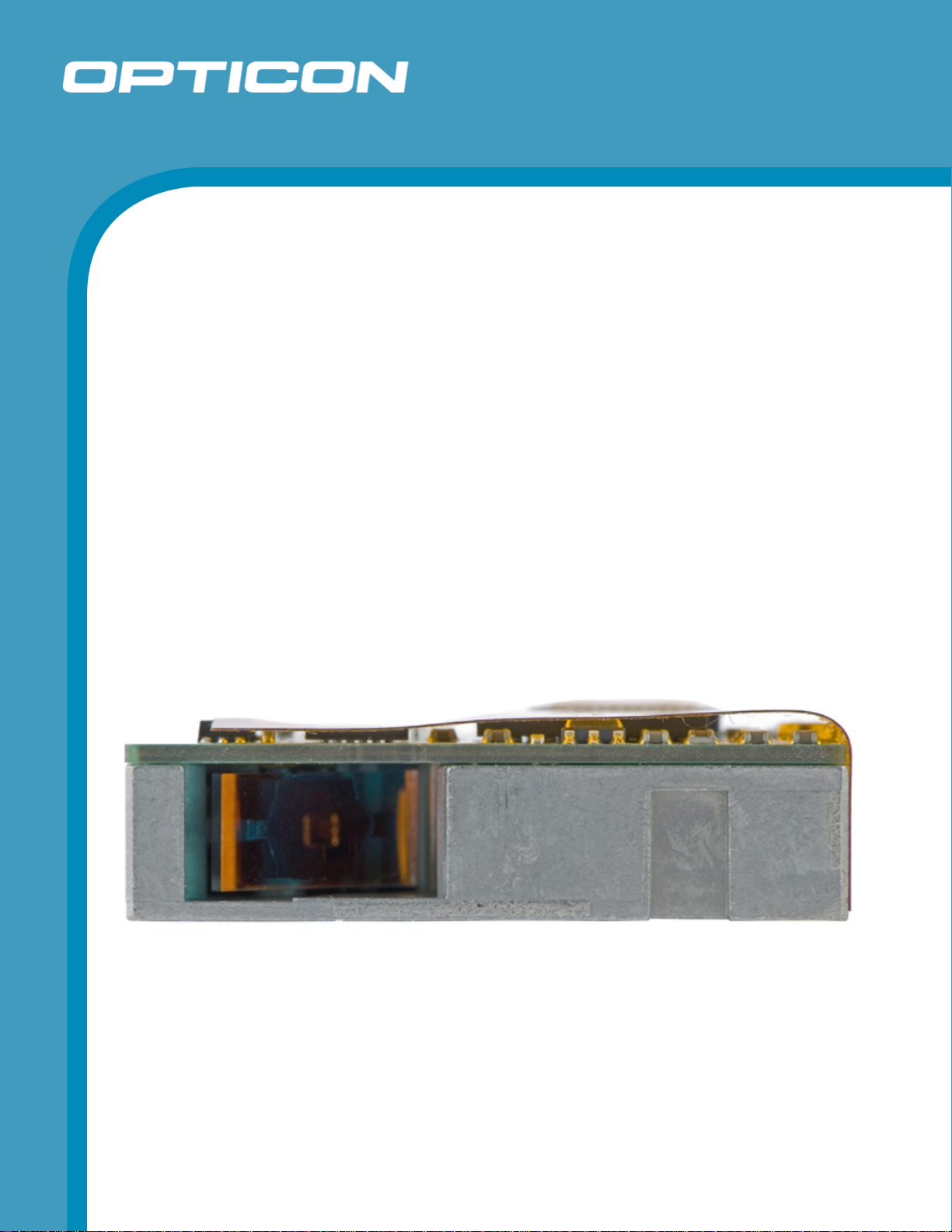
This manual provides specifications for the MDL 1000 laser scan engine.
2. Overview
The MDL 1000 laser scan engine is a compact laser barcode scan engine which can be
installed in various handheld products, such as a cellular terminal. When scanning a target at
the closest point, it has the ability to scan up to 44 mm wide at an angle of 44°. The use of a
short-wavelength red laser beam enhances visibility when scanning lines.
A decoder is built into the MDL 1000 that enables this scan engine to decode barcodes after
scanning and output the information using serial communication.
The MDL 1000 complies with the Restriction of Hazardous Substances (RoHS).
3. Physical Features
Opticon
MDL 1000
3.1. Dimensions
W 28.0 x D 18.0 x H 8.0 mm
3.2. Weight
10 g (max.)
4. Environmental Specifications
4.1. Operating Temperature and Humidity
Temperature: -20° C to 65° C
Humidity: 5% to 90% RH
4.2. Storage Temperature and Humidity
Temperature: -30° C to 70° C
Humidity: 5% to 90% RH
4.3. Ambient Light Immunity
Decoding performance is guaranteed when the range of illumination on a barcode
surface is between zero and the following values:
Incandescent light 4,000 lx
Fluorescent light 4,000 lx (excluding high-frequency lighting)
Sunlight 80,000 lx
5
Page 6
Opticon
MDL 1000
Specifications Manual
Conditions
Barcode Sample: OPTOELECTRONICS Test Sample
PCS: 0.9
Resolution: 0.25 mm
Symbology: 9-digit Code 39
Quiet zone: 10 mm
N/W ratio: 1:2.5
Distance: 150 mm
Angle (see note below): α = 0° β = 15° γ = 0°
Curvature: R = ∞
Power supply voltage: 3.3 V
Direct light or specular reflection from a light source should be prevented from entering
the acceptance area.
Note: α, β and γ respectively represent pitch, skew and tilt. Please see section 7 for how
these values are defined.
5. Electrical Specifications
5.1. Absolute Maximum Ratings
Parameter Symbol Value Unit
Power supply voltage (V
Input voltage VIN -0.3 to Vcc +0.3 V
to GND) VCC 3.9 V
CC
6
Page 7

5.2. Electrical Characteristics
Electrical characteristics: VCC=3.3 V, Ta=25° C
Item Symbol Conditions Min Typ Max Unit
Operating Voltage VCC 3.0 — 3.6 V
Opticon
MDL 1000
Specifications Manual
Operating Current 1 I
Operating Current 2 I
Idle Current I
Aiming Current I
Low Power Current I
Rush Current Peak I
Output Voltage
(Decode LED)
Output Voltage
(Txd, RTS)
READ State
OP1
READ State 95 110 mA
OP2
IDLE State
IDL
AIMING State
AIM
Low Power State
LOW
PEEK
High VIH V
Low V
High VOH I
High
IL
< 8mA VCC-0.6
OH
VOH I
< 5uA VCC-0.6
OH
—
—
—
— —
—
x 0.8
CC
— —
(Low Power
State)
Low V
I
OL
High VOH I
High
I
V
OH
< 8mA
OL
< 4mA VCC-0.6
OH
< 5uA VCC-0.6
OH
— —
(Low Power
State)
Low V
Iy < 4mA
OL
— —
110 125 mA
30 40 mA
50 65 mA
1400 uA
500 1000 mA
— —
V Input Voltage
VCC x 0.2 V
— —
— —
V
V
0.4 V
— —
— —
V
V
0.4 V
Output Voltage
(Power Down)
High
(Low Power
VOH I
< 5uA VCC -0.6
OH
— —
V
State)
Low VOL I
IIN
< 4mA
OL
— —
VIN=3.3V — —
0.4 V
-10
μA
Input Current
=0V — —
V
IN
50
μA
7
Page 8

VCC
Trigger
Opticon
MDL 1000
Specifications Manual
ON
OFF
OFF
ON
peek
2.5ms Max
Iop1
Iop2
I
IDL
500us Max
IDLE
5.3. Power Mode Transition
8.33 ~ 12.5ms
READ IDLE
Low Power
Current Waveform
Figure 1: Current waveform
Figure 2: Current waveform
When in low power mode, the state of operation changes automatically from “Power On”
to “Low Power”.
If there is a transition to the “IDLE” state by enabling “CTS ON” or “WAKE ON” in “Low
Power Mode,” it will automatically go back to the “Low Power” state in a second unless
transitioning to another mode.
8
Page 9

6. Optical Specifications
6.1. Laser Scan Specifications
Parameter Specification Unit
Light-emitting element Red laser diode -
Emission wavelength 650 ±10 (25° C) nm
Light output 1.0 or less mW
Scanning method Bi-directional scanning -
Scanning speed 100 ±20 scans/s
6.1.1. Tilt of Laser Scan Line
Maximum tilt between both ends of laser scan line: Less than 1.2° upward tilt from
the scan origin.
Maximum of 3.1 mm when measured at a point 150 mm away from the scan
origin. (The skew angle of this measurement was zero degrees.)
Measurement was done from the center of scan line.
Opticon
MDL 1000
Specifications Manual
Scan angle: 54 ±5 ° Scan angle
Read angle: 44 (Min) °
6.1.2.
Curvature of Scan
Maximum gap between the straight line connecting both ends of the laser scan
line and the actual laser scan line: Less than 1.27° curvature from the scan origin.
Maximum of 3.3 mm curvature when measured at a point 150 mm away from the
scan origin. (The skew angle of this measurement was zero degrees.)
Measurement was done from the center of scan line.
C
u
r
v
a
t
u
r
e
t
l
i
T
Figure 3: Laser scan tilt and curvature
Horizontal Line
9
Page 10

Specifications Manual
7. Technical Specifications
The conditions for technical specifications are as follows, unless otherwise specified in each
section.
Conditions
Ambient temperature and humidity Room temperature and room humidity
(5 to 35º C / 45% to 85% RH)
Ambient light 500 to 900 lx (excluding high-frequency lighting)
Background Barcode = black
Space = white
Margin = white
Background of label = black
Power supply voltage 3.3 V
Decoding test Approve the performance when decoding is
successful in all ten tests.
(Decoding is deemed successful when completed
in 0.5 seconds or less.)
Opticon
MDL 1000
7.1. Print Contrast Signal (PCS)
0.45 or higher (over 70% of reflectivity of space and quiet zone).
Reflectance of white bar-Reflectance of black bar
PCS=
Reflectance of white bar
Scanning performance may decline if dirt or scratches mar the optical window. Keep the
optical window clean.
10
Page 11

7.2. Scan Area and Resolution
7.2.1. Depth of Field
The depth of the decoding field is measured from the edge of the exit window.
The decoding area is rectilinear near the exit window and expands in an arc
centered on a virtual reference point in the distance.
Opticon
MDL 1000
Specifications Manual
Resolution
0.127
0.15
0.25
0.5
1.0
60~120
50~150
50~260
50~420
70~650
(in millimeters)
Figure 4: The depth of a decoding field.
Conditions
Barcode Sample: OPTOELECTRONICS Test Sample
N/W Ratio
Angle
Curvature
1:2.5
α = 0°, β = 15°, γ = 0°
R = ∞
Resolution Symbology PCS Quiet Zone Digits
1.0 mm Code 39 0.9 25 mm 1
0.5 mm Code 39 0.9 18 mm 3
0.25 mm Code 39 0.9 10 mm 8
0.15 mm Code 39 0.9 7 mm 10
0.127 mm Code 39 0.9 5 mm 4
11
Page 12

7.3. Pitch, Skew, and Tilt
Pitch angle: α = ±35°
Skew angle: β = ±50° (Excluding dead zone)
Dead zone: β = ±8° (There are some areas in which decoding fails due to specular
reflection)
Tilt Angle: γ = ±20°
-
α
+
γ
-
+
Opticon
MDL 1000
Specifications Manual
Figure 5: Pitch, skew, and tilt
Conditions
Barcode Sample: OPTOELECTRONICS Test Sample
Distance
Label Pitch, Skew Angle, Dead Zone
Angle
110 mm from the exit window
PCS = 0.9, Resolution = 0.25 mm, Symbology = 9-digit Code 39,
Quiet Zone = 10 mm, N/W Ratio = 1:2.5
Tilt Angle
PCS = 0.9, Resolution = 0.26 mm, Symbology = 13-digit JAN, Quiet Zone = 10 mm
Curvature: R = ∞, Skew Angle = β +15° (for measuring Pitch Angle and Tilt Angle)
β
-
+
12
Page 13

7.4. Curvature
With 8-digit JAN/UPC/EAN barcodes, decoding performance is guaranteed when
R≥15 mm.
With 13-digit JAN/UPC/EAN barcodes, decoding performance is guaranteed when
R≥20 mm.
R
Opticon
MDL 1000
Specifications Manual
Figure 6: Curvature
Conditions
Barcode Sample: OPTOELECTRONICS Test Sample
PCS = 0.9, Resolution = 0.26 mm, Quiet Zone = 10 mm
Distance
Angle
110 mm from the edge of the exit window
Skew Angle β = +15°
13
Page 14

8. Interface Specifications
8.1. Interface Connector
Opticon
MDL 1000
Specifications Manual
Signal Pin
I/O Features
No.
TEST 1 I Input for the Test: High or Open = Normal Operation, Low =
Maintenance Mode *
VCC 2 — Power Supply: DC 3.0V to 3.6V
GND 3 — Ground
Rxd 4 I Input Serial Data, CMOS Logic Level
Txd 5 O Output Serial Data, CMOS Logic Level
CTS 6 I Clear to Send, CMOS Logic Level
RTS 7 O Request to Send, CMOS Logic Level
Power Down 8 O Power Down Output, CMOS Logic Level High = Low Power State
Buzzer 9 O Buzzer Control Pulse Output, CMOS Logic Level Low = Buzzer On
Decode LED 10 O LED Output, CMOS Logic Level Low = LED On
Aim/Wake 11 I Aiming / Wakeup Input, CMOS Logic Level Low = Aim/Wake
Trigger 12 I Trigger Input, CMOS Logic Level Low = Trigger
Connector used was produced by KYOCERA ELCO Corporation.
Product No. 04 6238 012 010 883+
12 pin 0.5 mm pitch FFC connector Bottom contact (Gold-plated terminal)
14
Page 15

8.2. Interface Circuit
Pin No. Signal Circuitry
Opticon
MDL 1000
Specifications Manual
1
Test Terminal
VCC
100K
High = Normal Operation Mode
Low = Maintenance Mode
TEST
2 VCC —
3 GND —
4
Rxd Input
VCC
100K
Rxd
5
Txd Output
VCC
100K
Txd
Power Down
6
CTS Input
VCC
100K
CTS
7
RTS Output
Power Down
VCC
100K
RTS
15
Page 16

Pin No. Signal Circuitry
Opticon
MDL 1000
Specifications Manual
8
9
10
11
VCC
100K
Power Down Output
High = Low Power State
Power Down
VCC
Buzzer Output
Power Down
100K
High = OFF
Low = ON
Power Down
Decode LED Output
VCC
100K
Buzzer
High = OFF
Low = ON
Power Down
VCC
100K
Decode LED
Aim/Wake Input
Low = Aim / Wake
Aim / Wake
12
VCC
100K
Trigger Input
Low = Trigger
Trigger
16
Page 17

9. Integration Specifications
9.1. Connection to the Host System
Please use a cable developed in accordance with specifications provided by the
connector manufacturer to connect the MDL 1000 decoder board with the host system.
Opticon
MDL 1000
Specifications Manual
Manufacturer
Cable No
Cable Length
Signal Connection
Molex Incorporated.
98266-0119
70 mm (maximum)
12-pin using a single-sided FPC
The cable with connector can also be obtained at Opticon:
• Cable length 51 mm Product No. 11438.
10. Serial Number
The serial number shown below is affixed to the MDL 1000.
Figure 7: Serial number diagram
Uppercase: Management Barcodes
(Symbology: Code 39, resolution: 0.12 to 0.2, N/W ratio = 1:2.5 to 1:3)
Lowercase: Model names, serial numbers (The height of the letters is 1.2 ±0.3)
*Serial number starts from 0000001 and is in order regardless of the lot number.
17
Page 18

11. Packaging Specifications
Size of the package after assembly: W 355 x D 290 x H 185 mm
帯電防止袋(青色)
Antistatic Bag (blue)
65 X 100
65× 100
( 5E0002)
クッション ダンボール
Cardboard Cushion
Top Panel
(天板)
Package Tray
梱包トレイ
B93007-04
B93007- 04
MDL-1000
MDL - 1 0 0 0
Cardboard
ダンボール
Opticon
MDL 1000
Specifications Manual
Package Tray with Cardboard Top Panel
ダンボール
Cardboard
梱包トレイにダンボールで
Pile up 6 of Those Set of Trays in a Box
6段積み重ねる
( 梱包数量は150個単位とする)
(25 engines on one tray. 150 engines in one box.)
ダンボール
Cardboard Sheet
Bottom Plate
(底板)
Package Box
梱包箱
No. 35 (5B0004)
No. 35(5B0004)
Attach Bar Code Labels for
国内向外装箱バーコードラベルを貼る
(refer to the applicable recital)
(備考参照)
the Shipment
蓋をして
Figure 8: Packaging
Note: The “RO” mark labeled on the package tray or package box guarantees that the
applicable product has passed our test of RoHS restrictions compliance (the restriction of the
use of certain hazardous substances in electrical and electronic equipment, 2002/95 EC).
However, this document does not have any legal weight in the European Union.
18
Page 19

12. Durability
12.1. Electrical Noise
No malfunction occurred when sinusoidal electrical noise (50 Hz -100 kHz, < 0.1Vp-p)
was added to a power supply line.
Conditions
Barcode Sample: OPTOELECTRONICS Test Sample
PCS 0.9
Resolution 0.25 mm
Symbology 9-digit Code 39
Quiet Zone 10 mm
N/W Ratio 1:2.5
Distance 150 mm
Opticon
MDL 1000
Specifications Manual
Angle α = 0° β = 15° γ = 0°
Curvature R = ∞
Power Supply Voltage 3.3 V
12.2. Shock
No malfunction occurred after the following drop test.
Drop Test: Fixed an MDL 1000 inside a dummy case and dropped it on its top, bottom,
front, back, left, right, top-left, top-right, bottom-left and bottom-right sides from 1.8
meters above a concrete floor. Repeated this routine ten times
12.3. Vibration Strength
No malfunction occurred after the following vibration test.
Vibration test: Increase the frequency of the vibration from 12 Hz to 200 Hz with
accelerated velocity 32.3 m/s
this routine for 2 hours to X direction, 2 hours to Y direction, and 4 hours to Z direction.
13. Reliability
MTBF (Mean Time Between Failures) of this product except for the laser diode and the
scan unit is 30,000 hours.
Life cycle of the laser diode is 10,000 hours and that of the scan unit is also 10,000
hours.
2
(3.3G) for 60 minutes in non-operating state. Repeated
The estimate of MTBF and product life cycle is based on standard operation of the
product within the recommended temperature range and without extreme electronic or
mechanical shock.
19
Page 20

14. Regulatory Compliance
14.1. Laser Safety
The scan engine emits laser beams.
JIS C6802: 2005: Laser class 2
IEC60825-1+A2:2001 Class 2
FDA CDRH Laser class II. Complies with 21 CFR 1040.10 and 1040.11 except for
deviations pursuant to laser notice No. 50 dated June 24, 2007.
Class II laser devices are not considered to be hazardous when used for their intended
purpose. Avoid staring into the laser beam.
14.2. RoHS
RoHS: The restriction of the use of certain hazardous substances in electrical and
electronic equipment, 2002/95 EC.
Opticon
MDL 1000
Specifications Manual
15. Safety
Handle this product carefully. Do not deliberately subject it to any of the following.
15.1. Shock
Do not throw or drop the scanner.
Do not place heavy objects on the cables.
15.2. Temperature Conditions
Do not use the scan engine at temperatures outside the specified range.
Do not pour boiling water on the scanner.
Do not throw the scan engine into the fire.
Do not forcibly bend the cables at low temperatures.
15.3. Foreign Materials
Do not immerse the scan engine in liquids.
Do not subject the scan engine to chemicals.
15.4. Other
Do not plug/unplug the connectors before disconnecting the power.
Do not disassemble this product.
Do not place the product near a radio or a TV receiver, as the scan engine may cause
reception problems.
The scan engine may be damaged by voltage drops.
The scan engine may not perform properly in environments when placed near a flickering
light, such as a computer monitor, television, etc.
20
Page 21

16. Mechanical Drawing
Opticon
MDL 1000
Specifications Manual
Figure 9: Mechanical drawing
21
 Loading...