

Page 1
User’s Manual
LH2 Fixed Position 2D Imager
25-ULH2R101-01 Preliminary
This version of the manual supports rmware 2232 and greater. Release date: Mar 05
Page 2

Statement of Agency Compliance
The LH2 has been tested for compliance with FCC regulations and
was found to be compliant with all applicable FCC Rules and Regu-
lations.
IMPORTANT NOTE: To comply with FCC RF exposure compliance
requirements, this device must not be co-located or operate in
conjunction with any other antenna or transmitter.
CAUTION: Changes or modications not expressly approved by
the party responsible for compliance could void the user’s authority
to operate the equipment.
The LH2 has been tested for compliance to CE standards and
guidelines and was found to conform to applicable CE standards,
specically the EMC requirements EN 55024, ESD EN 61000-4-2,
Radiated RF Immunity EN 61000-4-3, ENV 50204, EFT EN 61000-
4-4, Conducted RF Immunity EN 61000-4-6, EN 55022, Class B
Radiated Emissions, and Class B Conducted Emissions.
The LH2 can be set to use targeting lasers. If the targeting lasers are
activated, do not stare into the beams. The LH2’s targeting lasers
have been rated as Class IIa Lasers by IEC 60825-1.
The LH2 has been tested by an independent electromagnetic compat-
ibility laboratory in accordance with the applicable specications and
instructions.
Page 3

LH2 User’s Manual
Copyright © 2004 the Opticon, Inc..
All Rights Reserved.
The software described in this manual may only be used in accordance with the terms of its license
agreement.
No part of this publication may be reproduced in any form or by any means without written permission
from the Opticon, Inc. This includes electronic or mechanical means such as photocopying or recording
in information storage and retrieval systems.
NO WARRANTY. This technical documentation is provided AS-IS. Further, the documentation does
not represent a commitment on the part of Opticon, Inc. Opticon, Inc. does not warrant that it is
accurate, complete or error free. Any use of the technical documentation is at the risk of the user.
Opticon reserves the right to make changes in specications and other information contained in this
document without prior notice, and the reader should in all cases consult Opticon to determine whether
any such changes have been made. Opticon shall not be liable for technical or editorial errors or
omissions contained herein; nor for incidental or consequential damages resulting from the furnishing,
performance, or use of this material. Opticon, Inc. does not assume any product liability arising out of or
in connection with the application or use of any product or application described herein.
NO LICENSE. No license is granted, either by implication, estoppel, or otherwise under any intellectual
property rights of The Opticon, Inc. Any use of hardware, software and/or technology of the Opticon, Inc.
is governed by its own agreement.
All other product names mentioned in this manual may be trademarks of their respective companies and
are hereby acknowledged.
The software and/or products of Opticon, Inc. include inventions that are patented or that are the subject
of patents pending.
Page 4

Table of Contents
Organization of this Manual 8
Chapter 1 9
Introduction and Getting Started 9
Product Overview 9
Quick Start-Up Procedure 10
Chapter 2 13
Technical Specication 13
OPTICAL 13
ELECTRICAL 13
ENVIRONMENTAL 14
PHYSICAL 14
SYMBOLOGIES 14
PINOUTS 14
ORDERING INFORMATION 15
Chapter 3 17
Positioning the Imager for Optimal Performance 17
Achieving Optimum Performance 17
1) Distance to the Bar Code 17
Focal Distance 17
Depth-of-Field 17
LH2 Decode Zone 19
2) Avoiding Specular Reection 20
3) Quality Bar Code Labels 20
Barcode Readability Index 20
Code Readability Index Rule: 21
4) Imager Field of View & Resolution 22
Left Trigger Optimization Matrix 27
Page 5

Right & Left Trigger Optimization Matrix 27
Continuous Trigger Optimization Matrix 28
Right Trigger Optimization Matrix 28
Application Notes 29
Tips for Achieving High Throughput 29
Tips for Insuring Highest Data Integrity 29
Chapter 4 31
Conguring the Imager 31
Programming Menus & Commands 31
Default Settings 31
RS-232 Interface Setting Defaults 31
Symbology Defaults: 32
Control Setting Defaults: 32
Chapter 5 33
Application Engineering Support 33
Technical Assistance and Support 33
Common Causes of Poor Performance 33
Modied and/or Customized Imagers 34
Chapter 6 35
Imager Servicing and Maintenance 35
How to use the Appendix? 37
Appendix A 37
Programming Menus & Commands 37
Programming Bar Codes 38
CRB Files 39
Example: test1.crb 40
General Options 41
Reset to Factory Defaults 41
Save Settings 42
Page 6

Clear All CodeXML Rules 43
Reader ID & Firmware Version 44
Example: test2.crb 45
Barcode Readability Index 46
Software Trigger 48
Read Near and Far Field 48
Read Near Field only 48
Read Far Field only 48
Symbology Options 49
Aztec Symbology 49
Codabar Symbology 50
Codablock F Symbology 51
Code 128 Symbology 52
Code 93 Symbology 53
Code 39 Symbology 54
Composite Symbologies 56
Data Matrix Symbology 57
Interleaved 2 of 5 Symbology 58
Maxicode Symbology 60
Micro PDF 417 Symbology 61
MSI Plessy Symbology 62
PDF 417 Symbology 63
Postal Symbologies 64
QR Code Symbology 66
RSS Symbology 68
UPC / EAN / JAN Symbologies 70
Communication Parameters 72
Baud Rate 72
Data Bits 74
Page 7

Stop Bits 75
Parity 76
Hardware Settings 77
Beep Volume 77
Laser Targeting 78
Laser Brightness 79
Left Key Programming 80
Right Key Programming 81
Continuous Scan 82
Continuous Scan 82
Continuous Scan - Trigger Delays 84
Duplicate Scan Delay 85
Advance Settings 86
Decode Time & LED’s for Non Standard Inks 86
Targeting Zone Tolerance 88
Windowing 90
VGA & SXGA Mode 92
Prex & Sufx Settings 93
Prex Settings 93
Sufx Settings 95
Optimization Matrix 97
SET 1 - Serial Commands for a Single Trigger 99
SET 1 - Barcodes for a Single Trigger 99
SET 2 - Barcodes for Continuous Trigger 100
SET 2 - Serial Commands for Continuous Trigger 100
Appendix B 101
Mechanical Layout 101
Page 8

Organization of this Manual
This manual provides the necessary instructions for installing and using an Opticon LH2 Fixed Position
Imager. The manual is organized as follows:
Chapter 1 Introduction and Getting Started
Describes the general operation of a LH2 Fixed Position Imager. Also provides a Quick
Start-Up Procedure that allows you to begin using the imager immediately.
Chapter 2 Technical Specications
Provides complete specications, including mechanical details, optical performance,
RS232 communications and other technical data.
Chapter 3 Positioning the Imager for Optimal Performance
Provides detailed instructions and tips for mounting and positioning the imager to
obtain the best scanning performance. Application Notes describe guidelines for
maximizing specic characteristics.
Chapter 4 Conguring the Imager
Describes how various parameters can be programmed to customize the imager for
your specic application.
Chapter 5 Application Engineering Support
Discusses the most common questions and concerns when adapting a LH2 Fixed
Position Imager in your application.
Chapter 6 Imager Servicing and Maintenance
Discusses the LH2 Fixed Position Imager warranty, maintenance and cleaning
procedures.
Appendices Detailed Supporting Information
Provides detailed information in specic areas such as the programming commands for
conguring various parameters of the LH2 Fixed Position Imager.
Page 9

Chapter
1
Chapter 1
Introduction and Getting Started
Product Overview
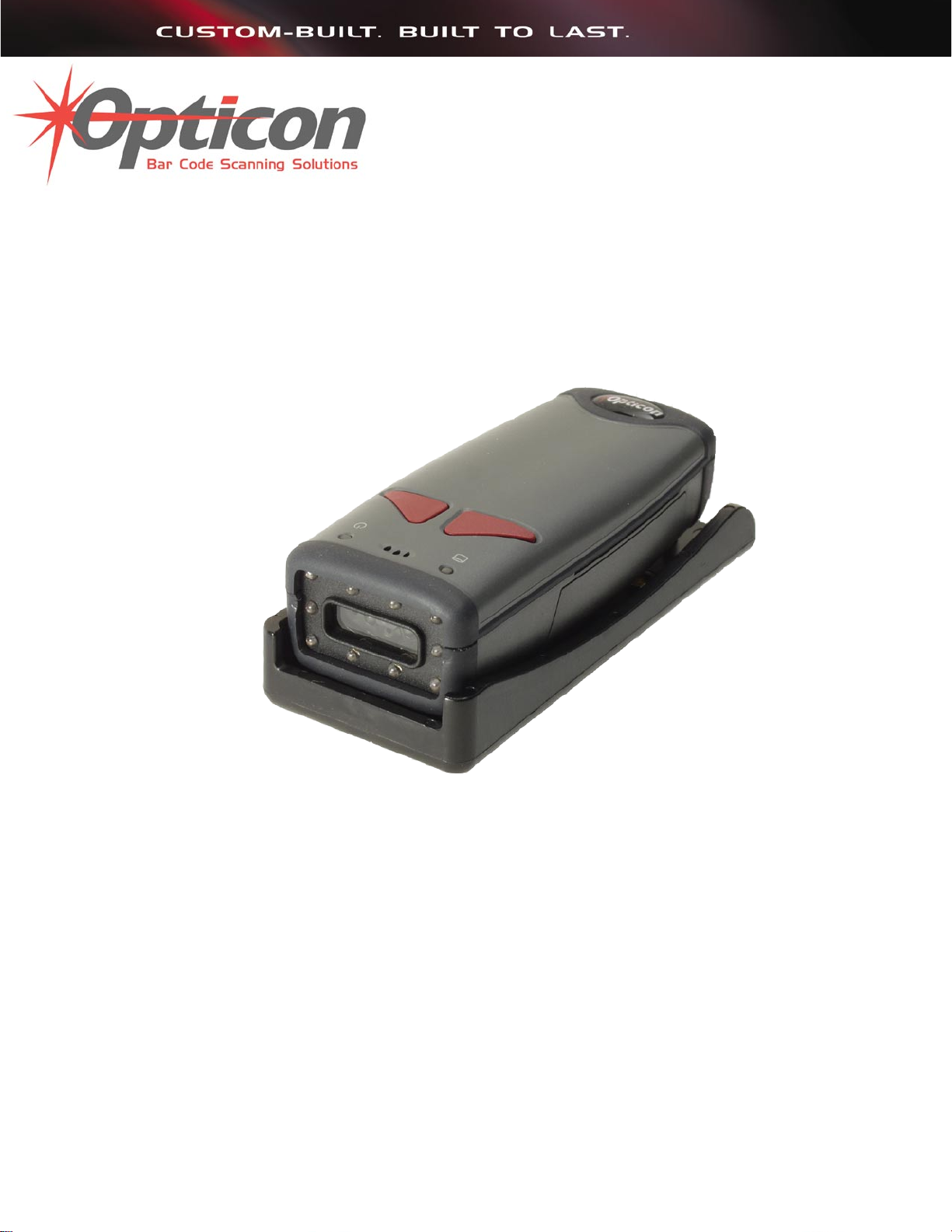
The LH2 xed position imager is truly a revolutionary new 2D imager. The omnidirectional
decoding allows the reading of linear, stacked linear and matrix bar codes in any
orientation.
These state-of-the-art imagers with superior 32-Bit, 400 mHz microprocessors provide a
one piece solution combining illumination, imaging and decoding in an extremely small
package.
Dual optics used by the 1.3 million pixel SXGA (1280 x 1024) CMOS sensor provide
exceptional depth of eld. The near and far eld cameras can be programmed to be
switched ON and OFF in different combinations to tailor the reading capabilities of the
LH2 to t your applications.
The laser beam facilitates targeting. The adjustable targeting zone allows precise selection
of specic bar codes in the eld of view. The LH2 can be customized with advanced logic
through the internal embedded application engine. The embedded engine may be utilized
to intelligently process or manipulate scanned data before it is sent to an application.
Advanced functions such as Barcode Readability Index provide quantitative measures
for optimizing imager settings to realize maximum performance. The LH2 is rugged and
built to last. These 100% solid state imagers use proven CMOS technology, assuring
continuing performance and high reliability. It is designed for rough handling in tough
environments and has a small footprint to t into tight spaces.
The LH2 is available in standard RS232 interface. Custom mounting options, cable
lengths, connector types and pinouts are available.
9
Page 10

Chapter 1
11
Quick Start-Up Procedure
This section is for those who wish to start using the imager before reading the complete
manual. In only a few steps the imager will be operable.
Follow the appropriate steps depending upon whether your LH2 is congured to operate
with a RS232 interface.
Chapter 1
Turn off the power to your PC and connect the imager to the RS232 communications port
depending on your cable conguration.
Note: You must provide +5 Volt DC power to the imager. This can be accomplished using
the power supply available from Opticon. If the power supply is obtained from another
source verify that it is identied with the CE mark. Turn on the power to the PC.
1) If you are operating in a Microsoft Windows 95/98/ 2000/ XP environment, you can set
the communication parameters using Hyper Terminal as follows:
• Open Hyper Terminal.
This can be done from Start>Programs>Accessories> Communications
• Select Hypertrm.exe to create a New Connection
• In the Connection Description dialog screen enter a name for the new le. If
desired, select an Icon. Click OK
• In the Connect To (Phone Number) dialog screen, in the box entitled: Connect
using. Select the communication port, for example, “Direct to Com 1” Click OK
• In the Com 1 Properties screen, enter the appropriate Port Settings:
Bits per second = 57600
Data bits = 8
Parity = None
Stop Character = 1
Handshaking = None
Click OK
• The hyper-terminal folder you just created will open. From the File pull-down
menu, select Properties then click on the Setting Tab
• In the Properties Settings dialog screen, Select Terminal keys for the Function,
arrow and control key; then Select ANSI for Emulation; the Back scroll buffer line
can remain at the default 500
10
Page 11

• Click on the ASCII Setup button. In the ASCII Setup screen, select Echo typed
locally so that any keyboard commands you input will appear on your screen. Click
OK. This returns you to the Properties Setting. Click OK
2) Your PC and the imager should now communicate.
3) To verify that the imager and the PC are communicating properly, send the following
command from your PC keyboard to receive a response from the imager.
Send these commands and at the end of the command send a carriage return.
( <┘ represents a carriage return)
;>PA7<┘
I<┘
Note: Be sure to use capital letters, e.g. “I”, not “i”.
4) The LH2 will send back the rmware version of the Imager.
Example:
Xap/i2232223006000010002363A06 sd+sq
Chapter 1
5) Send the following command to turn OFF the serial command mode.
PA8<┘
This Quick Start-Up procedure will get you started. However, to best understand the full
capabilities of this imager, you should read the complete manual.
11
Page 12

Chapter 1
This page is left blank intentionally
12
Page 13

Chapter 2
Technical Specication
OPTICAL
Field of View 21º horizontal x 15º vertical (approx)
Optical Resolution 1024 x 1280
Chapter
2
Bar Code Density
Linear 0.11 mm (4.2 mil) minimum
2D 0.15 mm (5.8 mil) minimum
Min. PCS Value 0.35
Pitch ±60º
Skew ±60º
Rotation ±180º
ELECTRICAL
Voltage 2.5 to 5.5 VDC
Current
Operating 140 mA
Standby 3 mA
Maximum 310 mA
Interface RS232
13
Page 14

Chapter 2
15
ENVIRONMENTAL
Temperature
Operating 0º to +40º C (+32º to +104º F)
Storage -20º to +60º C (-4º to +140º F)
Humidity 5 - 95% RH non-condensing
Shock Withstands multiple drops to concrete of 2 m (6.56 ft)
Regulatory FCC Class B, CE Certied
Targeting Beam Class IIA Visible Laser Diode (630 nm)
PHYSICAL
Chapter 2
Case Material PC/ABS Plastic
Dimension (L x W x H) 118 x 51 x 40 mm (4.6 x 2 x 1.6 in)
Weight 136 g (4.8 oz)
Cable Length
RS232 1.8 m (6 ft) straight
SYMBOLOGIES
2D BAR CODES MaxiCode, PDF417, Data Matix, QR Code, MicroPDF,
UCC RSS Composite, Aztec Code
LINEAR BAR CODES Code 39, Code 128, UPC/EAN/JAN, I 2 of 5, Codabar
(NW7), Code 93, UCC RSS, POSTNET, PLANET,
Japanese Post, Australia Post
PINOUTS
9 Pin Female mini-DIN Connector
Pin Function
1 Trigger
2 SD
3 RD
5 Signal Ground
9 +5 VDC
14
Page 15

ORDERING INFORMATION
Part No. Description
LH2RRIS-056 LH2, RS232 Interface
LH2-R1-SK1 Developers test and evaluation kit
* Additional industry standard conguration mounting brackets available.
Developer’s Test and Evaluation Kit is available that contain all the items needed to install
and evaluate the LH2 imager.
The LH2-R1-SK1 kit includes:
• LH2 Imager
• Cable (Connects LH2 to the Evaluation Board)
• Engineering Test & Evaluation Board
• 5V Power Supply
• Extension Cable (Connects host PC to Evaluation Board)
• User Manual
Chapter 2
15
Page 16

Chapter 2
This page is left blank intentionally
16
Page 17

Chapter
3
Chapter 3
Positioning the Imager for Optimal Performance
Achieving Optimum Performance
Four items greatly impact performance:
1) Distance (from the scan window) to the bar code
2) Specular Reection; and
3) Quality of Bar Code Labels
4) Imager eld of view and resolution
1) Distance to the Bar Code
The operation of the imager is similar to a camera. If you photograph an object that is
out of focus, the resulting picture will be blurry. The same is true with the imager. If the
bar code label is out of focus, the imager may have difculty decoding what appears to
be fuzzy bars and spaces.
Focal Distance
Ideally, the distance from the window of the imager to the bar code label should be equal
to the focal distance of the imager.
Depth-of-Field
Just as with a camera, the imager has a depth-of-eld. It can read bar codes that are not
precisely at the focal distance - maybe a little closer, or a little farther away. However, if
the bar code label is positioned too far from the focal distance, the imager may not be
able to successfully decode it.
The depth-of-eld varies based on the density of the bar code, i.e., the thickness of the
bars. Very high density bar codes (which have very narrow bars) are readable over a
17
Page 18

Chapter 3
19
much shorter distance range than low density bar codes with larger bars.
The following chart in gure 3.1 shows the “typical” depth-of-eld (closest to farthest
reading distances ) for the LH2 imagers. The actual performance may differ slightly from
unit to unit. Also, it is important to note that this data was measured under ideal conditions
using high quality bar code labels. In a “real world” environment the conditions will not be
as ideal. Therefore, the best practice is to position the imager at its focal distance rather
than at the extremes of its depth-of-eld.
The chart also shows the eld-of-view at various distances from the window. The eldof-view is the maximum width that the imager is capable of reading. A bar code label
positioned anywhere within this eld-of-view can be decoded. The eld-of-view is also a
measure of the widest bar code label that can be read. Remember: The width of a bar
code label includes not only the bars and spaces but also the required white space (quiet
zone) on each end.
Good design policy is to position the imager at its focal distance and at the center of the
eld-of-view. Do not position it near the extremes of the reading range.
Chapter 3
18
Page 19
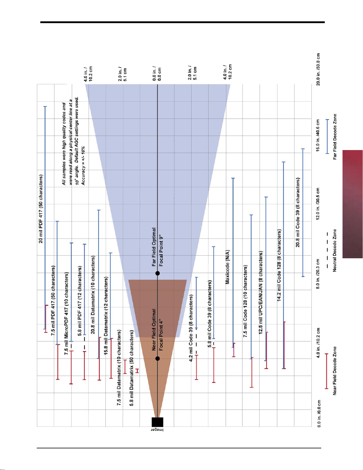
LH2 Decode Zone
Chapter 3
Figure 3.3
19
Page 20

Chapter 3
21
2) Avoiding Specular Reection
Do not position the imager at an angle that causes the LED illumination to be reected
directly back into the imager. This is called specular reection. Too much reected light
can “blind” the imager preventing a good decode.
If the bar code label is located on a at surface, specular reectivity occurs between 0 to 10
degrees off perpendicular. (See diagram) If the bar code label is located on a cylindrical
surface, such as a test tube, the angle of specular reection is measured tangent to the
curve. If the curved surface is also moving, there may be more than one position causing
specular reection.
3) Quality Bar Code Labels
The quality of the bar code label can affect the scanning performance. Poor quality labels
are more difcult to decode and may result in non-reads or potential misreads. The bar
code label should be printed to specications. This means that the bars are printed within
spec, with the correct widths, no ink spread, crisps edges and no voids. There should be
a sufcient quiet zone on both end of the bar code label. For best results, the paper or
label stock should have a matte nish to diffuse light. The print contrast signal (which is
a comparison of the reectance of the bars and the background stock) should be as high
as practical.
Chapter 3
Barcode Readability Index
The Readability Index provides a measurement of a specic symbol’s ease or difculty to
be decoded by the LH2. The Readability Index is specic to the LH2, and should not be
confused with a verication quality measurement.
The Readability Index is a blend of information obtained from the internal operations of the
decoding algorithm pertaining to contrast, symbology construct, error detection, forward
error correction (if applicable), and other symbology-specic characteristics.
The Readability Index is a score on a scale of 01 (very poor) to 100 (very readable).
Due to differences based on motion, skew, reection, focus, and ambient lighting, the
Readability Index on the same symbol may vary somewhat from read to read. However, a
poor contrast or damaged symbol will score lower than a high contrast undamaged symbol.
The Readability Index can be used as a quick check on the reliability of label generation or
marking systems. When determining the ideal distance from the reader to the symbol, and
constant ambient light, the Readability Index provides a symbol quality assurance tool and
check point for feedback to an overall label or marking quality control system.
The Readability Index is enabled by rst reading a CodeXML rule into the permanent LH2
Memory.
20
Page 21

Code Readability Index Rule:
The Reader will store the rule and reset, but will not output the Readability Index until the
Readability Index Output Enable code is read. To remove this rule, scan the Clear All Prex
& Sufx code in Appendix A.
Readability Index Output Enable
Once read, each time a data symbol is read, the index will be output, followed by a comma,
(,) followed by the decoded data.
Example:
Code Qual = 98, 071589812308
The Reader will continue to output the Readability Index upon every read until disabled,
either by reset or by reading the Readability Index Output Disable.
Readability Index Output Disable
Chapter 3
21
Page 22

Chapter 3
23
4) Imager Field of View & Resolution
The LH2’s dual eld optical system may be modied based on your scanning environment.
The LH2’s mega pixel imager may be set to the following two modes:
SXGA Mode: In standard SXGA mode (default), the 1.3 Million Pixel imager is divided
into near eld and far eld decode zones. In each zone the resolution is 1024 x 640 pixels
(see gure 3.2). In this mode of operation, the highest resolution, and therefore, widest
working range on symbols of all densities is achieved. The trade-off is the amount of
time the reader spends processing the image. This time can be reduced by optimization
functions.
If only the near eld is used (small, high density symbols), the far eld image can be
ignored. If only the far eld is used (large, lower density symbols), the near eld can be
ignored. Further optimization may be obtained by “windowing” the eld to a smaller area.
Each focal area may be narrowed by enabling the windowing feature found in Appendix
A.
VGA Mode: In VGA mode (optional selection), the 1.3 Million Pixels are sampled on a 4to-1 basis. This greatly reduces the amount of time necessary for the transfer of the image
to the CPU and the resulting processing time (gure 3.3). The trade-off for this increased
speed is a reduction in resolution and working range.
Chapter 3
NOTE: In the following section the LH2 can ONLY be programmed
by scanning the bar codes. For detail serial commands read the
Appendix A - Optimization Matrix section.
22
Page 23

1024
SXGA
Imaging Area
Far
Near
480
Far
640
640
Figure 3.2
320
Chapter 3
VGA
Imaging Area
Near
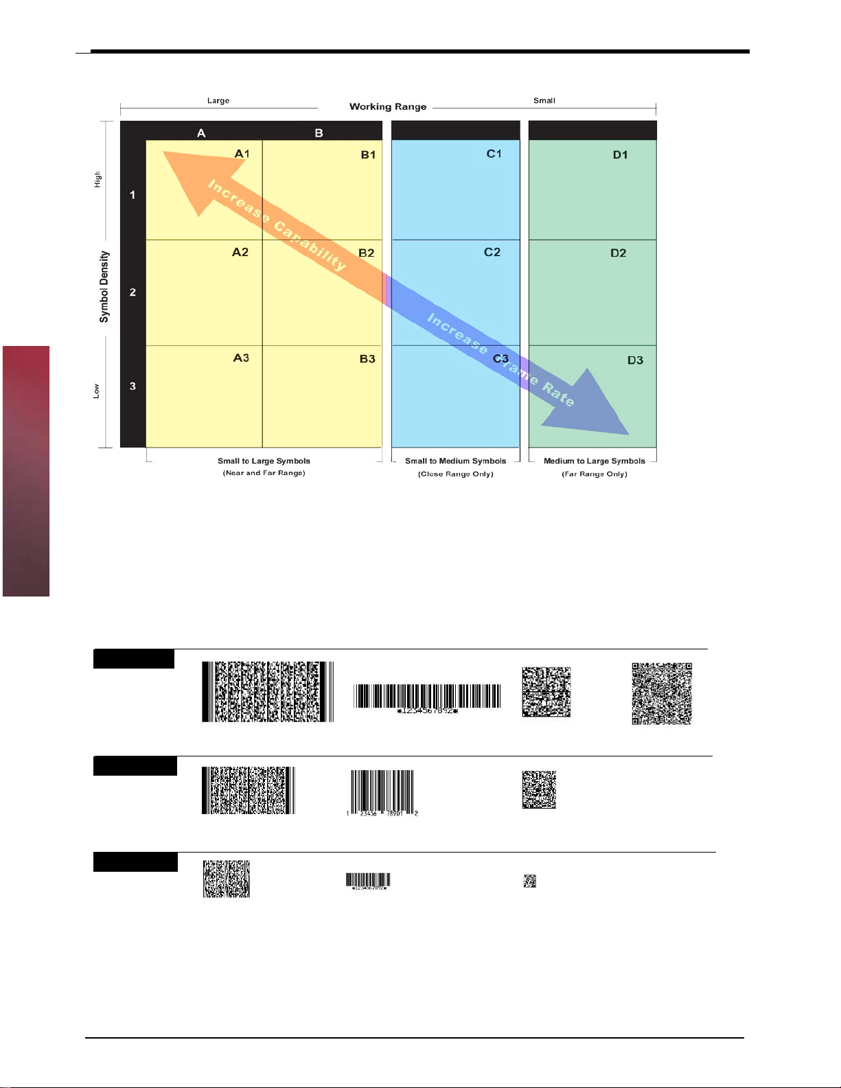
The LH2 may be easily optimized for any workplace. By setting a few parameters from your
scanning environment you can take advantage of the readers dual path 1.3 mega pixel imager
and 400 MHz processor.
If you are scanning large barcodes, small barcodes or even multiple sizes of different barcodes,
by dening the working range and the type of symbols the reader must process, the LH2 will
offer lightning fast decodes.
Look at the charts below to assess your environment. You may program each trigger on the LH2
unit for a different environment by scanning barcodes from the next few pages.
320
Figure 3.3
23
Page 24
Chapter 3
25
* Factory Default
Setting
* All triggers programmed to this setting at shipment
Chapter 3
Symbol Size - Here are a few approximate examples of large, medium and small symbols.
Figure 3.4
All of the codes below have been modied for representation purposes and do not scan
Large Symbols
PDF 417 - 20+ mil Code 128 - 14.2+ mil Data Matrix - 15+ mil QR Code - 15+ mil
Medium Symbols
Data Matrix - 10+ milUPC/EAN/JAN - 12.5+ milPDF 417 - 15+ mil
Small Symbols
Code 39 - 4.2+ milMicroPDF 417 - 7.5+ mil Data Matrix - 6.5+ mil
.
24
Page 25

When choosing the correct setting for your environment (i.e. printed labels, direct marks...)
we recommend trying several settings. For a large majority of users, the B1 or B3 settings are
satisfactory. If you would like to greatly improve the reader’s performance on medium to large
1-D codes, try the D1 or D3 setting, The chart and denitions below will help you understand
the readers conguration for each setting.
SXGA Mode
High
Near Field Decoding: On
Far Field Decoding: On
1
NF Resolution: 1024 x 640
FF Resolution: 1024 x 640
Decode Try Time: Long
SXGA Mode
Near Field Decoding: On
Far Field Decoding: On
2
NF Resolution: 832 x 640
FF Resolution: 1024 x 640
Decode Try Time: Normal
Symbol Density
SXGA Mode
Near Field Decoding: On
3
Low
Far Field Decoding: On
NF Resolution: 480 x 480
FF Resolution: 640 x 480
Decode Try Time: Short
Large
Working Range
Small
A B C
A1 B1 C1 D1
SXGA Mode
Near Field Decoding: On
Far Field Decoding: On
NF Resolution: 1024 x 640
FF Resolution: 1024 x 640
Decode Try Time: Normal
* Factory Default Setting
SXGA Mode
Near Field Decoding: On
Far Field Decoding: Off
NF Resolution: 1024 x 640
FF Resolution: NA
Decode Try Time: Normal
SXGA Mode
Near Field Decoding: Off
Far Field Decoding: On
NF Resolution: NA
FF Resolution: 1024 x 640
Decode Try Time: Normal
A2 B2 C2 D2
SXGA Mode
Near Field Decoding: On
Far Field Decoding: On
NF Resolution: 640x 512
FF Resolution: 832 x 640
Decode Try Time: Short
SXGA Mode
Near Field Decoding: On
Far Field Decoding: Off
NF Resolution: 640 x 640
FF Resolution: NA
Decode Try Time: Normal
SXGA Mode
Near Field Decoding: Off
Far Field Decoding: On
NF Resolution: NA
FF Resolution: 832 x 512
Decode Try Time: Normal
A3 B3 C3 D3
VGA Mode
Near Field Decoding: On
Far Field Decoding: On
NF Resolution: 480 x 320
FF Resolution: 480 x 320
Decode Try Time: Short
VGA Mode
Near Field Decoding: On
Far Field Decoding: Off
NF Resolution: 480 x 320
FF Resolution: NA
Decode Try Time: Short
VGA Mode
Near Field Decoding: Off
Far Field Decoding: On
NF Resolution: NA
FF Resolution: 480 x 320
Decode Try Time: Short
D
Chapter 3
Small to Large Symbols
Near and Far Range
Small to Medium Symbols
(Close Range Only)
* All triggers programmed to this setting at shipment
Medium to Large Symbols
(Far Range Only)
Denitions
Symbol Density: The amount of information versus the total area occupied by the symbol.
In order to achieve high density, the individual elements of a symbol must shrink. The highest
density symbols can only be resolved in the LH2 near-eld image, where the resolution of the
imager is 1024 x 640 DPI. Symbol density is usually expressed in “Mils” - ie, thousandths of
inches. This size refers to the smallest width of a linear barcode or the “cell size” (individual
square) in a matrix barcode.
Working Range: The range from nearest to farthest that the object (the target symbol)
can be resolved and decoded. Parameters that effect working range are SYMBOL DENSITY
and the OVERALL SIZE of the symbol, the SYMBOLOGY used, the reectivity of the surface,
the contrast of the symbol in relation to its background, the amount and type of illumination
available, and other environmental factors.
Resolution: Resolution is expressed in the table is the pixel array available for decoding a
25
Page 26

Chapter 3
27
symbol. It affects both the density and the size of the barcode that can be decoded.
Near Field (NF): The nearest eld of the LH2’s two image elds. The Near Field has the
highest resolution (1024 x 640 DPI). It has an optimal focal point of 4” (101.6 mm) away
from the lens of the reader. It has a size of 8.5” long (215.9 mm) by 4” wide (101.6 mm).
It has an overall viewing angle of 21° x 12°.
Far Field (FF): The farthest eld of the LH2’s two image elds. The Far Field has the
lowest resolution (480 x 320 DPI). It has an optimal focal point of 9” (228.6 mm) away from
the lens of the reader. It has a size of 4” wide (101.6 mm) at the optimal focal point.
Frame Rate: The number of decode attempts in a given amount of time.
Decode Try Time: The speed of decoding a given symbol. The time of decoding is
dramatically affected by the number of attempts at decoding images (frame speed)
available. An attempt includes the time used in the photographic exposure of an image,
and includes the transfer of the image to the CPU and the time taken to analyze the image,
locate a symbol, and decode the symbol into data or abandon the attempt because no data
could be derived.
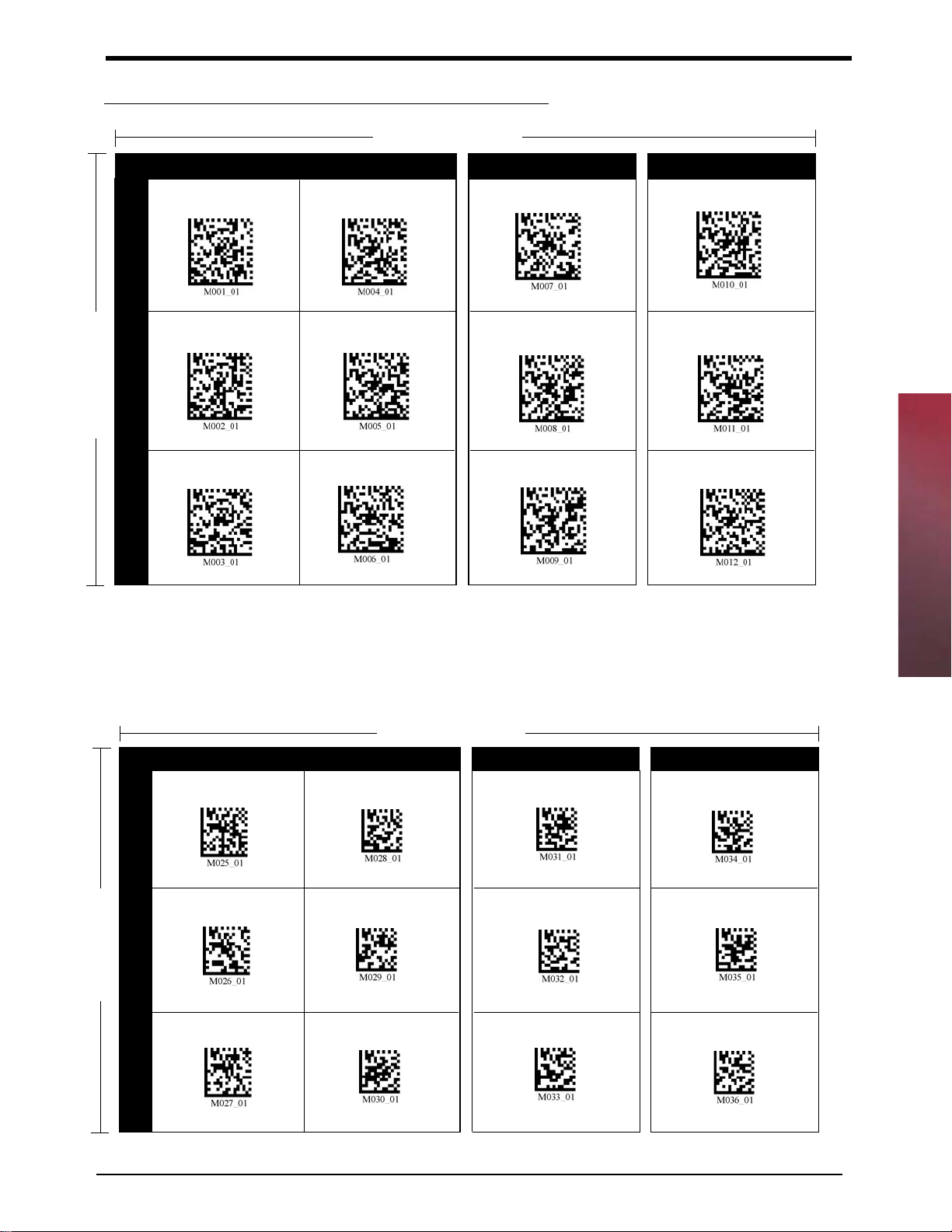
There are four different Optimization Matrix available.
1) Right & Left Key Optimization
Chapter 3
2) Left Key Optimization
3) Right Key Optimization
4) Continuous Trigger Optimization
You can use any of the options to ne tune the scanning performance of the LH2 to t your
application.
26
Page 27
Right & Left Trigger Optimization Matrix
High
1
2
Symbol Density
3
Low
Large
Working Range
Small
A B C
A1 B1 C1 D1
* Factory Default
A2 B2 C2 D2
A3 B3 C3 D3
D
Small to Large Symbols
Near and Far Range
* All triggers programmed to this setting at shipment.
After setting the conguration, you must scan the save settings code or your reader will lose its settings if the reader is powered off.
Small to Medium Symbols
(Close Range Only)
Left Trigger Optimization Matrix
Large
A B C
A1 B1 C1 D1
High
1
A2 B2 C2 D2
2
Symbol Density
A3 B3 C3 D3
Working Range
Medium to Large Symbols
(Far Range Only)
Small
D
Chapter 3
Low
3
Small to Large Symbols
Near and Far Range
Small to Medium Symbols
(Close Range Only)
Medium to Large Symbols
(Far Range Only)
27
Page 28
Chapter 3
29
Right Trigger Optimization Matrix
High
1
2
Symbol Density
3
Low
Chapter 3
Large
Working Range
Small
A B C
A1 B1 C1 D1
A2 B2 C2 D2
A3 B3 C3 D3
Small to Large Symbols
Near and Far Range
Small to Medium Symbols
(Close Range Only)
Medium to Large Symbols
(Far Range Only)
D
Continuous Trigger Optimization Matrix
High
1
2
Symbol Density
3
Low
Large
A B C
A1 B1 C1 D1
A2 B2 C2 D2
A3 B3 C3 D3
Working Range
Small
D
28
Small to Large Symbols
Near and Far Range
Small to Medium Symbols
(Close Range Only)
Medium to Large Symbols
(Far Range Only)
Page 29

Application Notes
Tips for Achieving High Throughput
In some applications your primary objective may be to achieve the highest possible
throughput rate. The following list identies the parameters and imager settings that
can maximize scanning and decode throughput speed. Note, by emphasizing maximum
throughput, other areas of performance may be affected. For example, the number of nonreads could increase.
If high throughput is critical, consider some or all of these settings:
• Only enable those symbologies that you will be decoding.
• Eliminate all sufxes and prexes.
• Minimize the number of redundant reads required before transmitting data.
• Transmit the decoded data at the highest baud rate, 115,200 baud.
• Disable buzzer functions.
Tips for Insuring Highest Data Integrity
There are several parameters that can enhance your condence that the correct bar code
data is transmitted. Note that by emphasizing the accuracy and security of the data other
areas of the imager operation may be affected, for example, you may not achieve the
highest throughput.
If accuracy and data integrity are critical, consider some or all of these settings:
• Program the imager to higher Decode Time. For example, program the imager
to decode a bar code exactly the same way with Extra Long Decode Time before
transmitting the data. The default settings for the LH2 are designed for optimal,
general purpose performance with good quality symbols on typical surfaces. For
poor quality barcodes or barcodes on non-standard surfaces (shiny, low-contrast),
the unit may require more time to process the barcode before the system abandons
the image and restarts on a new decode attempt. It may require manipulating LED’s
too.
• The quality of the printed bar code must be excellent.
• Do not use a symbology with poor internal verication, or subject to partial
decodes, such as 2 of 5 or MSI/Plessey.
Chapter 3
• Only enable those symbologies that you will be decoding.
• Transmit data at low baud rates to minimize communication errors.
29
Page 30

Chapter 3
This page is left blank intentionally
30
Page 31

Chapter
4
Chapter 4
Conguring the Imager
Since the operation of a LH2 imager is microprocessor controlled, it is possible to modify or
program its operation to match your specic application. Changes in parameter settings can
be changed or programmed in two ways:
(1) The rst method employs specially designed programming bar codes which instruct the
imager to modify specic parameters. You can scan any of the barcodes from Appendix A
to program the LH2.
(2) The imager can also be programmed by sending software instructions from the host PC
to the imager via the RS232 connection only for the commands that are available.
Programming Menus & Commands
Appendix A contains full instructions on how to congure the imager as well as a complete
listing of the host serial commands and programming bar codes that are available to
customize the imager for your application.
Default Settings
Default settings are indicated throughout the menus to follow.
To restore the “out-of-the-box” settings shown in the following table, use the Reset to
Factory defaults setting and Clear All Prex & Sufx barcode settings
RS-232 Interface Setting Defaults
Baud Rate 57600
Stop Bits 1
Data Bits 8
Parity None
31
Page 32

Symbology Defaults:
All 1D Codes ON
Aztec OFF
Codabar ON
Code 128 ON
Code 93 ON
Code 39 ON
Composite OFF
Data Matrix ON
DM Inverse OFF
DM Rect. ON
Interleaved 2 0f 5 ON
MaxiCode OFF
MSIP OFF
PDF 417 ON
Micro PDF OFF
Postal Codes OFF
QR OFF
Chapter 4
RSS OFF
UPC ON
Control Setting Defaults:
Left Button All Decodes
Right Button All Decodes
Beeper Volume High
Laser Targeting On
32
Time Stamp Off
Continuous Scan Off
Page 33

Chapter
5
Chapter 5
Application Engineering Support
Technical Assistance and Support
Opticon is eager to help you integrate the LH2 imager into your application. Our technical support staff
is available to answer any questions or work with you to adapt the imager to your specic situation.
We are happy to answer your questions, assist in conguring and positioning the imager for optimum
operation, and help resolve any problems you encounter. Call us at 1 (800) 636-0090.
Common Causes of Poor Performance
The most common reasons for poor scanning performance are listed below:
• Bar codes are not positioned at the focal distance of the imager.
• Specular reection is impacting the imager. Change the angle/position of the imager or the
bar code.
• Poor quality of printed bar codes. Bar codes are out of specication.
• The paper on which the bar code is printed is highly reective or has a glossy nish causing
light to be reected into the imager.
• The distance from the imager to the bar code is not suitable for the density of the bar code.
Or the density of the bar code beyond the imagers capability.
33
Page 34

Modied and/or Customized Imagers
Opticon will work with you to modify or customize imagers to match your requirements.
Imagers can be modied in terms of connectors type, pin-outs, cable length, default
settings, custom software and many other areas.
Opticon will modify imagers in our factory and ship you imagers that match your specic
requirements. By incorporating your modications directly into production imagers, you
receive imagers tailored for your need. They can be used immediately without the need for
further modication or rework.
Chapter 5
34
Page 35

Chapter
6
Chapter 6
Imager Servicing and Maintenance
The LH2 imager contains no user adjustable or serviceable parts in the interior of the imager. All
product service must be performed by the Opticon Service Department in Orangeburg, NY. Opening
the imager will void the warranty and could expose the operator to laser light.
CAUTION: The LH2 utilizes a laser for targeting purpose only. If the laser is activated, do not
stare into the beam.
The LH2 is warranted for 5 years including parts and workmanship. If you need warranty or out-ofwarranty repair, rst call 1-800-636-0090 to obtain a Returned Material Authorization (RMA)
number. You will be provided a number and shipping instructions. Please visit our web site for a detail
warranty statement.
http://www.opticonusa.com
There is no scheduled maintenance required for the LH2. The imager can be cleaned using a water
dampened, lint free or lens cloth. Be careful to avoid excessive moisture that would penetrate the
housing or obscure the window. While use of cleaning uids other than water are not recommended,
a neutral detergent or ethanol would be preferred if necessary. Do not use bleach at full or diluted
strength as damage to the painted case and/or window may result.
35
Page 36

This page is left blank intentionally
Chapter 6
36
Page 37

Appendix
A
Appendix A
Programming Menus & Commands
How to use the Appendix?
The appendix has all the programming commands laid out in a standard format in the
whole section. All the programming commands have these attributes - Command Name,
Usage, Description, Default, Programming Code, Note and Options. For certain commands
you might not have all the attributes and are intentionally not mentioned.
Following are the details on each attributes of a programming command.
Command Name:
Usage:
Description:
Default:
The general name of a programming command.
A brief description of the command name and the function of the
command.
Here you will nd a detail description on the programming
command.
The default setting will be mentioned here.
37
Page 38

Appendix A
39
Programming Code: Serial Command:
A bar code to program the command. If a serial command is available then you can
send the program the LH2 via serial port.
All the commands end with a carriage
return.
<┘ represents a carriage return.
Appendix A
Example:
P%081<┘
Note:
Options:
Extra notes on the command will be mentioned here. Usually these
notes are important so please pay special attention to this section.
If extra programming command options are available then it will
be listed here. It follows the same syntax as mentioned in the
Programming Code and Serial Command section.
Programming Bar Codes
The LH2 imagers are pre programmed at the factory with default settings representing the
settings most commonly used by our customers. In most applications, the imager will work
right out of the box without the need for additional programming.
You can scan the barcodes from the appendix to change the settings of the LH2. The LH2
will automatically recognize the barcode as a programming barcode and change the settings
accordingly. You can scan multiple programming barcodes to change the settings.
NOTE: Always scan the “Save Settings“ bar code to save all the changes you made. If
you do not save the settings then the next time you power ON the LH2, it will go to the
previously saved settings.
38
Page 39

CRB Files
The CRB le is a convenient method for creating and maintaining a set of commands that
can be easily sent to the reader. The CRB les are regular text les with the .crb extension.
These CRB les can be created in any text editor such as “Notepad” and saved with the le
extension of .crb.
The CRB le can be sent to the reader using any standard serial program. You can use
HyperTerminal Program to send the le. Please refer the topic in Chapter 1 - Quick StartUp Procedure to set up the HyperTerminal program. After setting the connection use the
Transfer pull-down menu, select “Send Text File...“ (gure) and then select the le you want
to send to the LH2.
Appendix A
The CRB le allows for combining multiple functions into a single le.
NOTE: You can comment your CRB le with a semicolon(;) as shown below.
The standard format of the CRB le is
;>PA7 ;enable programming mode
commands
commands
.
.
commands
~ ;save the settings
PA8 ;disable the programming mode
39
Page 40

For example you can create a test.crb le that contains commands to enable Aztec symbology
and make the reader beep three times. Note you can also comment your CRB le with a
semicolon (;) as shown below.
NOTE: The only command which is not ignored in the CRB le when a semicolon
(;) is used is ;>PA7. In all other cases anything that follows the semicolon is
commented out.
Appendix A
Example: test1.crb
;>PA7 ;enable programming mode
P%501 ;enable aztec symbology
#%03 ;beep reader 3 times
~ ;save the settings
PA8 ;disable the programming mode
40
Page 41

General Options
Command Name:
Usage:
Description:
Default:
Programming Code: Serial Command:
Reset to Factory Defaults
Use this option to reset the imager to RS232 factory defaults.
This command will set the imager to factory defaults. This command
is extremely helpful if you have set the imager to different settings
and want to erase those settings and reset the imager back to the
factory defaults. It does not erase the Clear Prex & Sufx
commands.
ON
J<┘
P%1b1<┘
P%420<┘
P%081<┘
General Options
Note:
Options:
This code does not reset the Prex & Sufx settings to factory
defaults. In order to reset the Prex & Sufx settings to factory
defaults, use the “Erase Prex” and “Erase Sufx“ commands.
---
41
Page 42

General Options
43
Command Name:
Save Settings
Usage:
Description:
Default:
Programming Code: Serial Command:
General Options
This command saves the current settings on the imager.
Always use this command to save any the changes you make to the
imager. If you change the settings on the reader and do not use this
command then the imager will not save them if you turn the power
OFF. The imager will default to the previously saved settings next
time you power ON.
---
~<┘
Note:
Options:
---
---
42
Page 43

Command Name:
Clear All CodeXML Rules
Usage:
Description:
Default:
Programming Code: Serial Command:
Notes:
Options:
Clears any rules and also the prex and sufx settings.
This command will clear any special command rules and prex or
sufx settings from the imager.
---
1<┘
5<┘
See the Prex/Sufx section to clear only the prex or sufx.
---
General Options
43
Page 44

General Options
45
Command Name:
Reader ID & Firmware Version
Usage:
Description:
General Options
To nd out the Reader ID and Firmware version of the imager.
You will get a text string with your rmware version and LH2 ID
number (see below):
Xap/iVVVVWWWWXXXXSSSSSSSSSSPXX sd+sq
Xap/i - Opticon Internal ID
VVVV is the application rmware version number (4 digits)
WWWW is the bootloader rmware version number (4 digits)
XXXX is reserved (4 digits)
SSSSSSSSSS Reader’s serial number (10 digits)
P is “A” if running rmware is the application, “B” if bootLoader
XX - Opticon Internal ID
sd+sq - Reserved characters
Example:
Xap/i2098201206000010002363A06 sd+sq
Default:
Programming Code: Serial Command:
Note:
---
I<┘
Opticon, Inc. will periodically release new rmware for LH2 units.
For information on latest rmware versions, call Opticon at (800)
636-0090. To upgrade the rmware please visit Opticon web site at
http://www.opticonusa.com to download the latest les.
Options:
44
---
Page 45

Example: test2.crb
;>PA7 ;enable programming mode
J ;4 line commands to reset the imager
P%1b1
P%420
P%081
I ;check the rmware id
~ ;save the settings
PA8 ;disable the programming mode
General Options
On sending the test2.crb le, the LH2 will be reset to factory defaults and on your screen
you will receive the Firmware ID string from the imager.
45
Page 46

General Options
47
Command Name:
Barcode Readability Index
Usage:
Description:
General Options
The Readability Index provides a measurement of a specic symbol’s
ease or difculty to be decoded by the LH2.
The Readability Index is specic to the LH2, and should not be
confused with a verication quality measurement.
The Readability Index is a blend of information obtained from the
internal operations of the decoding algorithm pertaining to contrast,
symbology construct, error detection, forward error correction (if
applicable), and other symbology-specic characteristics.
The Readability Index is a score on a scale of 01 (very poor) to
100 (very readable). Due to differences based on motion, skew,
reection, focus, and ambient lighting, the Readability Index on
the same symbol may vary somewhat from read to read. However,
a poor contrast or damaged symbol will score lower than a high
contrast undamaged symbol. The Readability Index can be used as a
quick check on the reliability of label generation or marking systems.
When determining the ideal distance from the reader to the symbol,
and constant ambient light, the Readability Index provides a symbol
quality assurance tool and check point for feedback to an overall
label or marking quality control system.
The Readability Index is enabled by rst reading a CodeXML rule into
the permanent LH2 Memory.
Default:
Programming Code: Serial Command:
Notes:
There is No Bar code Readability Index installed.
---
The Reader will store the rule and reset, but will not output the
Readability Index until the Readability Index Output Enable code is
read. To remove this rule, scan the Clear All Prex & Sufx code.
46
Page 47

Options:
Programming Code: Serial Command:
Readability Index Output Enable
P%da1<┘
Once read, each time a data symbol is read, the index will be output, followed by a comma,
(,) followed by the decoded data.
Example:
Code Qual = 98, 071589812308
The Reader will continue to output the Readability Index upon every read until disabled,
either by reset or by reading the Readability Index Output Disable.
Read Index Output Disable
P%da0<┘
General Options
47
Page 48

Command Name:
Software Trigger
Usage:
Description:
Default:
Programming Code:
(There are no programming barcodes)
Notes:
General Options
Options: Serial Command:
Read Near and Far Field $%03<┘
Simulates a trigger.
This command will post a single simulated software
trigger. You can read with both the elds, only the near
eld or only the far eld.
---
See continuous trigger option.
Read Near Field only $%05<┘
Read Far Field only $%06<┘
48
Page 49

Symbology Options
Command Name:
Usage:
Description:
Default:
Programming Code: Serial Command:
Aztec OFF (Default) P%500<┘
Aztec Symbology
Sets the Aztec bar code symbology options.
This command allows you to turn ON or OFF the Aztec 2D bar code
symbology.
Aztec is OFF
Options:
Programming Code: Serial Command:
Aztec ON P%501<┘
Symbology Options
49
Page 50

51
Symbology Options
Command Name:
Codabar Symbology
Usage:
Description:
Default:
Programming Code: Serial Command:
Codabar ON (Default) P%6f1<┘
Options:
Programming Code: Serial Command:
Sets the Codabar bar code symbology options.
This command allows you to turn ON or OFF the Codabar bar code
symbology.
Codabar is ON
Symbology Options
Codabar OFF P%6f0<┘
50
Page 51

Command Name:
Codablock F Symbology
Usage:
Description:
Default:
Programming Code: Serial Command:
Codablock ON P%6d0<┘
Options:
Programming Code: Serial Command:
Sets the Codablock F bar code symbology options.
This command allows you to turn ON or OFF the Codablock F bar
code symbology.
Codablock F is OFF
P%ce1<┘
Codablock OFF (Default) P%6d1<┘
P%ce0<┘
Note:
When Codablock F and Code 128 decoding are enabled, there is some
danger of mistakenly decoding a damaged Codablock F symbol as a Code
128 symbol. Therefore, whenever possible, Code 128 decoding should be
disabled when Codablock F decoding is enabled.
Symbology Options
51
Page 52

53
Symbology Options
Command Name:
Code 128 Symbology
Usage:
Description:
Default:
Programming Code: Serial Command:
Code 128 ON (Default) P%6d1<┘
Options:
Programming Code: Serial Command:
Sets the Code 128 bar code symbology options.
This command allows you to turn ON or OFF the Code 128 bar code
symbology.
Code 128 is ON
Symbology Options
Code 128 OFF P%6d0<┘
52
Page 53

Command Name:
Code 93 Symbology
Usage:
Description:
Default:
Programming Code: Serial Command:
Code 93 ON (Default) P%6c1<┘
Options:
Programming Code: Serial Command:
Sets the Code 93 bar code symbology options.
This command allows you to turn ON or OFF the Code 93 bar code
symbology.
Code 93 is ON
Code 93 OFF P%6c0<┘
Symbology Options
53
Page 54

55
Symbology Options
Command Name:
Code 39 Symbology
Usage:
Description:
Default:
Programming Code: Serial Command:
Code 39 ON (Default) P%6b1<┘
Sets the Code 39 bar code symbology options.
This command allows you to turn ON or OFF the Code 39 bar code
symbology.
Code 39 is ON
Disable Checksum is ON
Code 39 Extended Full ASCII is OFF
Options:
Programming Code: Serial Command:
Symbology Options
Code 39 OFF P%6b0<┘
Enable Checksum P%701<┘
Disable Checksum (Default) P%700<┘
54
Page 55

Programming Code: Serial Command:
Enable checksum and strip from result P%702<┘
Code 39 Extended Full ASCII ON P%491<┘
Code 39 Extended Full ASCII OFF (Default) P%490<┘
Symbology Options
55
Page 56

57
Symbology Options
Command Name:
Composite Symbologies
Usage:
Description:
Default:
Programming Code: Serial Command:
Composite ON P%344<┘
Options:
Programming Code: Serial Command:
Sets the Composite bar code symbology options.
This command allows you to turn ON or OFF the Composite bar code
symbology.
Composite is OFF
P%4a1<┘
Symbology Options
Composite OFF (Default) P%4a0<┘
56
Page 57

Command Name:
Data Matrix Symbology
Usage:
Description:
Default:
Programming Code: Serial Command:
Data Matrix ON (Default) P%161<┘
Options:
Programming Code: Serial Command:
Sets the Data Matrix 2D bar code symbology options.
This command allows you to turn ON or OFF the Data Matrix 2D bar
code symbology.
Data Matrix is ON
Data Matrix Inverse is ON
Data Matrix OFF P%160<┘
Data Matrix Inverse ON (Default) P%193<┘
Data Matrix Inverse OFF P%191<┘
Symbology Options
57
Page 58

59
Symbology Options
Command Name:
Interleaved 2 of 5 Symbology
Usage:
Description:
Default:
Programming Code: Serial Command:
I 2 of 5 ON (Default) P%6e1<┘
Options:
Programming Code: Serial Command:
Sets the Interleaved 2 of 5 bar code symbology options.
This command allows you to turn ON or OFF the Interleaved 2 of 5
bar code symbology.
I 2 of 5 is ON
Symbology Options
I 2 of 5 OFF P%6e0<┘
I 2 of 5 Two digits ON O%c91
I 2 of 5 Two digits OFF Q%c90
58
Page 59

Programming Code: Serial Command:
I 2 of 5 Four digits ON O%c92
I 2 of 5 Four digits OFF Q%c92
Symbology Options
59
Page 60

61
Symbology Options
Command Name:
Maxicode Symbology
Usage:
Description:
Default:
Programming Code: Serial Command:
Maxicode ON ---
Sets the Maxicode 2D bar code symbology options.
This command allows you to turn ON or OFF the Maxicode 2D bar
code symbology.
Maxicode is OFF
Symbology Options
Options:
Programming Code: Serial Command:
Maxicode OFF (Default) P%470<┘
Note:
For certain Maxicode (commonly used by UPS™) barcodes printed
on thermal labels may require to manipulate the LED’s on the LH2.
For more information on different settings, please refer to section
“Advanced Settings” on Page 86.
60
Page 61

Command Name:
Micro PDF 417 Symbology
Usage:
Description:
Default:
Programming Code: Serial Command:
Micro PDF 417 ON P%2a1<┘
Options:
Programming Code: Serial Command:
Sets the Micro PDF 417 2D bar code symbology options.
This command allows you to turn ON or OFF the Micro PDF 417 2D
bar code symbology.
Micro PDF 417 is OFF
Micro PDF 417 OFF (Default) P%c2a0<┘
Symbology Options
61
Page 62

63
Symbology Options
Command Name:
MSI Plessy Symbology
Usage:
Description:
Default:
Programming Code: Serial Command:
MSI Plessy ON P%4f1<┘
Options:
Programming Code: Serial Command:
Sets the MSI Plessy bar code symbology options.
This command allows you to turn ON or OFF the MSI Plessy bar code
symbology.
MSI Plessy is OFF
Symbology Options
MSI Plessy OFF (Default) P%4f0<┘
62
Page 63

Command Name:
PDF 417 Symbology
Usage:
Description:
Default:
Programming Code: Serial Command:
PDF 417 ON (Default) P%291<┘
Options:
Programming Code: Serial Command:
Sets the PDF 417 2D bar code symbology options.
This command allows you to turn ON or OFF the PDF 417 2D bar
code symbology.
PDF 417 is ON
PDF 417 OFF P%290<┘
Symbology Options
63
Page 64

65
Symbology Options
Command Name:
Postal Symbologies
Usage:
Description:
Default:
Programming Code: Serial Command:
Disable All Postal Codes (Default) P%4b0<┘
Options:
Programming Code: Serial Command:
Sets different Postal bar code symbology options.
This command allows you to turn ON or OFF different Postal bar
code symbologies.
All Postal Symbologies are OFF.
Symbology Options
Australian Post ON P%4b8<┘
Japan Post ON P%4b20000<┘
KIX ON P%4b200001<┘
Planet ON P%4b80<┘
64
Page 65

Programming Code: Serial Command:
Postnet ON P%4b2000<┘
Postnet and Planet ON P%4b2080<┘
Royal Mail ON P%4b200000<┘
Symbology Options
65
Page 66

67
Symbology Options
Command Name:
QR Code Symbology
Usage:
Description:
Default:
Programming Code: Serial Command:
QR Code ON P%2b1<┘
Options:
Programming Code: Serial Command:
Sets the QR Code 2D bar code symbology options.
This command allows you to turn ON or OFF the QR Code 2D bar
code symbology.
QR Code is OFF.
Checksum is Disabled.
Symbology Options
QR Code OFF (Default) P%2b0<┘
Enable Checksum P%481<┘
Disable Checksum P%480<┘
66
Page 67

Programming Code: Serial Command:
QR Code Inverse ON P%2b2<┘
Both Inverse and Standard ON P%2b3<┘
Symbology Options
67
Page 68

69
Symbology Options
Command Name:
RSS Symbology
Usage:
Description:
Default:
Programming Code: Serial Command:
All RSS Codes ON P%4c#31<┘
Options:
Programming Code: Serial Command:
Sets different RSS bar code symbology options.
This command allows you to turn ON or OFF different RSS bar code
symbologies.
All RSS Symbologies are OFF.
Symbology Options
All RSS Codes OFF (Default) P%4c0<┘
RSS Limited ON P%4c4<┘
RSS 14 and RSS 14 Truncated ON P%4c8<┘
68
Page 69

RSS 14 Stacked ON P%4c#16<┘
RSS Expanded ON P%4c1<┘
Symbology Options
69
Page 70

71
Symbology Options
Command Name:
UPC / EAN / JAN Symbologies
Usage:
Description:
Default:
Programming Code: Serial Command:
UPC ON (Default) P%6a1<┘
UPC Short Margin Disabled P%740<┘
Sets the UPC/EAN/JAN bar code symbology options.
This command allows you to turn ON or OFF the UPC/EAN/JAN bar
code symbology.
UPC is ON
UPC Short Margin is Disabled
Symbology Options
Options:
Programming Code: Serial Command:
UPC OFF P%6a0<┘
UPC Short Margin Enabled P%741<┘
70
Page 71

UPC Extension ON P%4d1<┘
UPC Extension OFF P%4d0<┘
Symbology Options
71
Page 72

Communication Parameters
73
Communication Parameters
Command Name:
Usage:
Description:
Default:
Programming Code: Serial Command:
57600 (Default) P%1cE100<┘
Baud Rate
Sets the RS-232 baud rate.
This command allows you to set different baud rates for RS-232
communication.
57600
Options:
Programming Code: Serial Command:
1200 P%1c4B0<┘
Communication Parameters
2400 P%1c960<┘
72
Page 73

4800 P%1c12C0<┘
9600 P%1c2580<┘
19200 P%1c4B00<┘
38400 P%1c9600<┘
115200 P%1c1C200<┘
Communication Parameters
73
Page 74

Communication Parameters
75
Command Name:
Data Bits
Usage:
Description:
Default:
Programming Code: Serial Command:
8 Data Bits (Default) P%1e8<┘
Options:
Programming Code: Serial Command:
Sets the RS-232 Data Bits options.
This command allows you to set the appropriate data bit
8 Data Bits is ON
7 Data Bits P%1e7<┘
Communication Parameters
74
Page 75

Command Name:
Stop Bits
Usage:
Description:
Default:
Programming Code: Serial Command:
1 Stop Bit (Default) P%1d1<┘
Options:
Programming Code: Serial Command:
Sets the RS-232 Stop Bits options.
This command allows you to set the appropriate stop bit
1 Stop Bit is ON
2 Stop Bit P%1d2<┘
Communication Parameters
75
Page 76

Command Name:
Parity
Usage:
Description:
Default:
Programming Code: Serial Command:
None (Default) P%220<┘
Options:
Programming Code: Serial Command:
Sets the RS-232 Parity options.
This command allows you to set appropriate parity.
None is ON
Even P%222<┘
Communication Parameters
Odd P%221<┘
76
Page 77

Hardware Settings
Command Name:
Usage:
Description:
Default:
Programming Code: Serial Command:
Beep High (Default) P%2664<┘
Beep Volume
Sets the buzzer volume.
This command allows you to set the beep volume to high or low.
You can also turn off the beep for a quite operation.
Beep is set to High volume.
Options:
Programming Code: Serial Command:
Beep Low P%2632<┘
Beep Off P%260<┘
Hardware Settings
77
Page 78

Hardware Settings
79
Command Name:
Laser Targeting
Usage:
Description:
Default:
Programming Code: Serial Command:
Laser ON (Default) P%0f1<┘
Sets the targeting laser beam.
This command allows you to turn ON or OFF the laser targeting
beam. The laser targeting beam is extremely help full to set the
imager during the initial set up. You can easily read a bar code by
pointing the laser dot in the center of the bar code.
Laser aiming dot is turned ON.
Options:
Programming Code: Serial Command:
Laser OFF P%0f0<┘
Hardware Settings
78
Page 79

Command Name:
Laser Brightness
Usage:
Description:
Default:
Programming Code: Serial Command:
High (Default) P%9C100<┘
Sets the targeting laser brightness.
This command allows you to change the brightness of the targeting
laser.
Targeting laser is set to High.
Options:
Programming Code: Serial Command:
Medium P%9C50<┘
Low P%9C1<┘
Hardware Settings
79
Page 80

Hardware Settings
81
Command Name:
Left Key Programming
Usage:
Description:
Default:
Programming Code: Serial Command:
Read with Both Imagers (Default) P%3a3<┘
Programs the left key to different options.
This command allows you to program the left key to perform different
functions. You can program the key so that it can make use of a
different imager ( Near / Far ) to read a barcode. This function is
useful while doing the initial setup.
The key is set to read with Both the imagers.
Options:
Programming Code: Serial Command:
Read with Far-Field Imager only P%3a6<┘
Read with Near-Field Imager only P%3a5<┘
Hardware Settings
80
Page 81

Command Name:
Right Key Programming
Usage:
Description:
Default:
Programming Code: Serial Command:
Read with Both Imagers (Default) P%393<┘
Programs the right key to different options.
This command allows you to program the right key to perform
different functions. You can program the key so that it can make use
of a different imager ( Near / Far ) to read a barcode. This function
is useful while doing the initial setup.
The key is set to read with both the imagers.
Options:
Programming Code: Serial Command:
Read with Far-Field Imager only P%396<┘
Read with Near-Field Imager only P%395<┘
Hardware Settings
81
Page 82

Continuous Scan
83
Continuous Scan
Command Name:
Usage:
Description:
Default:
Programming Code: Serial Command:
Both Near & Far Field ON P%c43<┘
Continuous Scan
Sets the imager in continuous scan mode.
This command allows you to set the imager into a continuous scan
mode. You can program the imager so that it can make use of
different imagers ( Near / Far ) to read a barcode in a continuous
mode.
Continuous Scan is OFF
Options:
Programming Code: Serial Command:
Near Field Only ON P%c45<┘
Far Field Only ON P%c46<┘
Continuous Scan
82
Page 83

Continuous Scan OFF (Default) P%c40<┘
83
Continuous Scan
Page 84

Continuous Scan
85
Command Name:
Continuous Scan - Trigger Delays
Usage:
Description:
Default:
Programming Code: Serial Command:
3 Seconds P%a2#3000<┘
Sets the delay time for continuous scan.
This command allows you to program the delay time between scans
while in continuous scan mode.
Delay is set to 0 seconds
Options:
Programming Code: Serial Command:
1 Second P%a2#1000<┘
0 Second (Default) P%a2#0<┘
Continuous Scan
84
Page 85

Command Name:
Duplicate Scan Delay
Usage:
Description:
Default:
Programming Code: Serial Command:
3 Seconds P%d63<┘
Sets the duplicate scan delay time in the continuous scan mode.
This command allows you to program the delay time between scans
while in continuous scan mode so that the imager will not read the
same bar code again.
Duplicate Scan Delay is set to 0 seconds
Options:
Programming Code: Serial Command:
1 Second P%d61<┘
0 Second (Default) P%d60<┘
85
Continuous Scan
Page 86

Advance Settings
87
Advance Settings
Command Name:
Usage:
Description:
Advance Settings
Default:
Decode Time & LED’s for Non Standard Inks
Sets the Decode Time and LED to read a bar code.
The default settings for the LH2 are designed for optimal, general
purpose performance with good quality symbols on typical surfaces.
For poor quality barcodes or barcodes on non-standard surfaces
(shiny, low-contrast), the unit may require:
• More time to process the barcode before the system abandons the
image and restarts on a new decode attempt.
• May require manipulating LED’s.
To allow for additional processing time or to change the LED settings
for marginal symbols, use one of the following commands.
Normal Decode Time is ON.
LED’s for Non Standard Inks are OFF.
Programming Code: Serial Command:
Extra Long Decode Time P%AA0200<┘
Note:
Options:
Programming Code: Serial Command:
Normal Decode Time (Default) P%AA100<┘
Utilizing this feature may affect the overall performance of the
reader, but “unreadable” barcodes may become readable.
86
Page 87

Short Decode Time P%aa80<┘
Long Decode Time P%AA180<┘
LED’s for Non Standard Inks ON P%b61<┘
Advance Settings
LED’s for Non Standard Inks OFF (Default) P%b60<┘
87
Page 88

Advance Settings
89
Command Name:
Targeting Zone Tolerance
Usage:
Description:
Advance Settings
Default:
Programming Code: Serial Command:
50 P%9d32<┘
Sets the Targeting Zone Tolerance of the imager.
This command allows you to program the decode accuracy of the
LH2. The 50 setting is the most accurate while the 1600 barcode is
the most tolerant. If you set the unit to a 50 setting, you have to aim
the targeting dot directly on the desired barcode for it to be read.
This setting is helpful when you are trying to read a single bar code
amongst a group of bar codes on a label.
Targeting Zone Tolerance is set to 1600.
Options:
Programming Code: Serial Command:
1600 (Default) P%9d640<┘
75 P%9d4b<┘
88
Page 89

100 P%9d64<┘
125 P%9d7d<┘
150 P%9d96<┘
Advance Settings
200 P%9dc8<┘
400 P%9d190<┘
89
Page 90

Advance Settings
91
Command Name:
Windowing
Usage:
Description:
Sets the imaging window size.
You may optimize the LH2 decode zone if the application only
requires one barcode format. If the size and density of the barcodes
to be scanned are consistent, please select the setting below that
best describes your environment.
Advance Settings
Default:
Programming Code: Serial Command:
1D & 2D Bar Codes P%53#640<┘
640 X 1024 Pixels (Default) P%54#1024<┘
The window size is set to 640 x 1024 pixels
P%C7#640<┘
P%C8#1024<┘
Options:
Programming Code: Serial Command:
1D Bar Codes Only P%53#200<┘
200 x 1024 Pixels P%c7#200<┘
Small 2D Bar Codes P%53#480<┘
480 x 480 Pixels P%54#480<┘
P%C7#480<┘
P%C8#480<┘
90
Page 91

Medium 2D Bar Codes P%53#512<┘
P%54#512<┘
P%C7#512<┘
P%C8#512<┘
Large 2D Bar Codes P%53#640<┘
P%54#640<┘
P%C7#640<┘
P%C8#640<┘
Advance Settings
91
Page 92

Command Name:
VGA & SXGA Mode
Usage:
Description:
Advance Settings
Default:
Programming Code: Serial Command:
SXGA Mode - 1280 x 1024 (Default) P%e20<┘
Sets the imager optical resolution.
User’s may optimize the LH2’s mega pixel (SXGA) imager (1280 x
1024) to a VGA (640 x 480). This feature is used to decrease the
pixel sampling area, which will greatly increase processing speed.
This is an advanced feature used for the rapid decoding of 1D/linear
barcodes and larger size 2D barcodes. Opticon recommends testing
this feature, as it may not work with certain high density codes.
Optical resolution is set to 1280 x 1024
P%640<┘
Options:
Programming Code: Serial Command:
VGA Mode - 640 x 480 P%e21<┘
P%640<┘
92
Page 93

Prex & Sufx Settings
Command Name:
Usage:
Description:
Default:
Programming Code: Serial Command:
Erase Prex (No Prex)
Prex Settings
Sets the prex for a bar code.
Scan the following barcodes to set appropriate prex. Make sure to
save settings on your reader before scanning the prex barcodes. If
you scan more than one prex you will receive each scanned prex
in your scanned data (i.e. If you scan comma prex twice, you will
get two comma prexes).
There is no prex by default.
---
Prex \ Sufx
Options:
Programming Code: Serial Command:
Prex - Comma
Prex - Space
Prex - Tab
---
---
---
93
Page 94

Prex \ Sufx
95
Prex - Carriage Return & Line Feed
---
Prex / Sufx
Note: For custom prex commands or to create serial commands for the above
settings download the Prex-Sufx Builder program from Opticon, Inc website at
http://www.opticonusa.com.
94
Page 95

Command Name:
Sufx Settings
Usage:
Description:
Default:
Programming Code: Serial Command:
Erase Sufx (No Sufx)
Sets the sufx for a bar code.
Scan the following barcodes to set appropriate sufx. Make sure to
save settings on your reader before scanning the sufx barcodes. If
you scan more than one sufx you will receive each scanned sufx
in your scanned data (i.e. If you scan comma sufx twice, you will
get two comma sufxes).
There is no sufxe by default.
---
Prex \ Sufx
Options:
Programming Code: Serial Command:
Sufx - Comma
Sufx - Space
---
---
95
Page 96

Sufx - Tab
---
Sufx - Carriage Return
Prex / Sufx
Sufx - Line Feed
Sufx - Carriage Return & Line Feed
---
---
---
Note: For custom sufx commands or to create serial commands for the above
settings download the Prex-Sufx Builder program from Opticon, Inc website at
http://www.opticonusa.com.
96
Page 97

Command Name:
Optimization Matrix
Usage:
Description:
Default:
Note:
Sets the imager to read different sizes of barcodes.
By setting a few parameters of the imager you can take advantage
of the dual path imager to read barcodes of different sizes. For your
convenience there are some preset standard settings created to read
different variety of barcodes. Look at the charts on the next page to
assess your environment.
More details are in Chapter 3, sub topic “4) Imager Field of
View & Resolution”.
The B1 non continuos mode setting is the default.
1. The tables on the next page represents the settings for each cell.
2. On the following pages there are 2 sets of tables (4 tables
altogether).
3. The rst set is the setting for single trigger and the second set is
for continuous trigger.
4. In each set one table has barcodes and the other table has the
corresponding serial commands. For example:
Barcode in cell A1 from SET 1 = Serial command in cell A1 from SET
1.
5. All the serial commands have a carriage return at the end of each
line.
6. If you use commands from SET 2 - “Continuous trigger“ then you
can turn OFF the continuous trigger by using the “Continuous Scan
OFF” command.
Optimization Matrix
97
Page 98

99
Optimization Matrix
* Factory Default
Setting
* All triggers programmed to this setting at shipment
Large
A B C
Optimization Matrix
SXGA Mode
High
Near Field Decoding: On
Far Field Decoding: On
1
NF Resolution: 1024 x 640
FF Resolution: 1024 x 640
Decode Try Time: Long
A1 B1 C1 D1
SXGA Mode
Near Field Decoding: On
Far Field Decoding: On
NF Resolution: 1024 x 640
FF Resolution: 1024 x 640
Decode Try Time: Normal
* Factory Default Setting
A2 B2 C2 D2
SXGA Mode
Near Field Decoding: On
Far Field Decoding: On
2
NF Resolution: 832 x 640
FF Resolution: 1024 x 640
Decode Try Time: Normal
Symbol Density
SXGA Mode
Near Field Decoding: On
Far Field Decoding: On
NF Resolution: 640x 512
FF Resolution: 832 x 640
Decode Try Time: Short
A3 B3 C3 D3
Low
SXGA Mode
Near Field Decoding: On
3
Far Field Decoding: On
NF Resolution: 480 x 480
FF Resolution: 640 x 480
Decode Try Time: Short
VGA Mode
Near Field Decoding: On
Far Field Decoding: On
NF Resolution: 480 x 320
FF Resolution: 480 x 320
Decode Try Time: Short
Working Range
SXGA Mode
Near Field Decoding: On
Far Field Decoding: Off
NF Resolution: 1024 x 640
FF Resolution: NA
Decode Try Time: Normal
SXGA Mode
Near Field Decoding: On
Far Field Decoding: Off
NF Resolution: 640 x 640
FF Resolution: NA
Decode Try Time: Normal
VGA Mode
Near Field Decoding: On
Far Field Decoding: Off
NF Resolution: 480 x 320
FF Resolution: NA
Decode Try Time: Short
Small
SXGA Mode
Near Field Decoding: Off
Far Field Decoding: On
NF Resolution: NA
FF Resolution: 1024 x 640
Decode Try Time: Normal
SXGA Mode
Near Field Decoding: Off
Far Field Decoding: On
NF Resolution: NA
FF Resolution: 832 x 512
Decode Try Time: Normal
VGA Mode
Near Field Decoding: Off
Far Field Decoding: On
NF Resolution: NA
FF Resolution: 480 x 320
Decode Try Time: Short
D
98
Small to Large Symbols
Near and Far Range
Small to Medium Symbols
(Close Range Only)
* All triggers programmed to this setting at shipment
Medium to Large Symbols
(Far Range Only)
Page 99

SET 1 - Barcodes for a Single Trigger
High
1
2
Symbol Density
3
Low
Large
A B C
A1 B1 C1 D1
* Factory Default
Working Range
Small
A2 B2 C2 D2
A3 B3 C3 D3
D
Small to Large Symbols
Near and Far Range
Small to Medium Symbols
SET 1 - Serial Commands for a Single Trigger
High
1
2
Symbol Density
Large
A B C
A1 B1 C1 D1
P%3C0D
P%3a0D
P%390D
A2 B2 C2 D2
P%3C0E
P%3a0E
P%390E
A3 B3 C3 D3
P%3C11
P%3a11
P%3911
P%3C12
P%3a12
P%3912
Working Range
P%3C15
P%3a15
P%3915
(Close Range Only)
P%3C14
P%3a14
P%3914
Medium to Large Symbols
(Far Range Only)
Optimization Matrix
Small
D
P%3C17
P%3a17
P%3917
P%3C18
P%3a18
P%3918
Low
3
P%3C0F
P%3a0F
P%390F
Small to Large Symbols
Near and Far Range
P%3C13
P%3a13
P%3913
P%3C16
P%3a16
P%3916
Small to Medium Symbols
(Close Range Only)
P%3C19
P%3a19
P%3919
Medium to Large Symbols
(Far Range Only)
99
Page 100

SET 2 - Barcodes for Continuous Trigger
High
1
2
Symbol Density
3
Low
Large
A B C
Working Range
Small
A1 B1 C1 D1
A2 B2 C2 D2
A3 B3 C3 D3
Small to Large Symbols
Near and Far Range
Small to Medium Symbols
(Close Range Only)
Medium to Large Symbols
(Far Range Only)
D
Optimization Matrix
SET 2 - Serial Commands for Continuous Trigger
Large
A B C
A1 B1 C1 D1
High
1
2
Symbol Density
3
Low
P%C40D
A2 B2 C2 D2
P%C40E
A3 B3 C3 D3
P%C40F
Working Range
P%C411
P%C414
P%C412 P%C415
P%C413 P%C416
Small
D
P%C417
P%C418
P%C419
Small to Large Symbols
Near and Far Range
Small to Medium Symbols
(Close Range Only)
Medium to Large Symbols
(Far Range Only)
100 101
 Loading...