

OpenEye OE-SHM2416, OE-SH4816, OE-X4U4816, OE-X4U4832, OE-X3U4816 User Manual
...
User Manual
Super Hybrid Series
SHM
OE-SHM2416
SH
OE-SH4816
www.openeye.net

OpenEye® SHM / SH NVR
Operations Manual
Manual Edition 32865AC – FEBRUARY 2015
©2015, OPENEYE
All Rights Reserved
No part of this document may be reproduced by any means, electronic or mechanical, for any purpose, except as
expressed in the Software License Agreement. OPENEYE shall not be liable for technical or editorial errors or
omissions contained herein. The information in this document is subject to change without notice.
The information in this publication is provided “as is” without warranty of any kind. The entire risk arising out of the
use of this information remains with recipient. In no event shall OPENEYE be liable for any direct, consequential,
incidental, special, punitive, or other damages whatsoever (including without limitation, damages for loss of business
profits, business interruption or loss of business information), even if OPENEYE has been advised of the possibility of
such damages or whether in an action, contract or tort, including negligence.
This software and documentation are copyrighted. All other rights, including ownership of the software, are reserved
to OPENEYE. OPENEYE, OpenEye, HDDR, and High Definition Digital Recorder are registered trademarks of
OPENEYE in the United States and elsewhere; Windows, and Windows XP Embedded are registered trademarks of
Microsoft Corporation. All other brand and product names are trademarks or registered trademarks of the respective
owners.
The following words and symbols mark special messages throughout this guide:
Text set off in this manner indicates information that is necessary for proper operation of the
product.
Text set off in this manner indicates information that may be helpful.
Text set off in this manner indicates that failure to follow directions could result in damage
to equipment or loss of information.
OPENEYE
Liberty Lake, WA ● U.S.A.
32865AC 3

IMPORTANT SAFEGUARDS
1. Read Owner’s Manual – After unpacking this product, read the owner’s manual carefully, and follow all the
operating and other instruction
2. Power Sources – This product should be operated only from the type of power source indicated on the label. If
not sure of the type of power supply to your home or business, consult product dealer or local power company
3. Ventilation – Slots and openings in the cabinet are provided for ventilation and to ensure reliable operation of
the product and to protect it from overheating, and these openings must not be blocked or covered. The product
should not be placed in a built-in installation such as a bookcase or rack unless proper ventilation is provided or
the manufacturer’s instructions have been adhered to.
4. Heat – The product should be situated away from heat sources such as radiators, heat registers, stoves, or other
products that produce heat.
5. Water and Moisture – Do not use this product near water.
6. Cleaning – Unplug this product from the wall outlet before cleaning. Do not use liquid cleaners or aerosol
cleaners. Use a damp cloth for cleaning.
7. Power Cord Protection – Power-supply cords should be routed so that they are not likely to be walked on or
pinched by items placed against them, paying particular attention to cords at plugs, convenience receptacles,
and the point where they exit from the product.
8. Overloading – Do not overload wall outlets, extension cords, or integral convenience receptacles as this can
result in a risk of fire or electrical shock.
9. Lightning – For added protection for this product during storm, or when it is left unattended and unused for long
periods, unplug it from the wall outlet. This will prevent damage to the product due to lightning and power line
surges.
10. Object and Liquid Entry Points – Never insert foreign objects into the recorder, other than the media types
approved by OpenEye, as they may touch dangerous voltage points or short-out parts that could result in a fire
or electrical shock. Never spill liquid of any kind on the product.
11. Accessories – Do not place this product on an unstable cart, stand, tripod, bracket, or table. The product may
fall, causing serious personal injury and serious damage to the product.
12. Disc Tray – Keep fingers well clear of the disc tray as it is closing. Neglecting to do so may cause serious
personal injury.
13. Burden – Do not place a heavy object on or step on the product. The object may fall, causing serious personal
injury and serious damage to the product.
14. Disc – Do not use a cracked, deformed, or repaired disc. These discs are easily broken and may cause serious
personal injury and product malfunction.
15. Damage Requiring Service – Unplug the unit from the outlet and refer servicing to qualified service personnel
under the following conditions:
When the power-supply cord or plug is damaged.
If liquid has been spilled, or objects have fallen into the unit.
If the unit has been exposed to rain or water.
If the unit does not operate normally by following the operating instructions. Adjust only those controls that
are covered by the operating instructions as an improper adjustment of other controls may result in damage
and will often require extensive work by a qualified technician to restore the unit to its normal operation.
If the unit has been dropped or the enclosure has been damaged.
When the unit exhibits a distinct change in performance – this indicates a need for service.
16. Servicing – Do not attempt to service this product as opening or removing covers may expose the user to
dangerous voltage or other hazards. Refer all servicing to qualified personnel.
17. Replacement Parts – When replacement parts are required, be sure the service technician has used
replacement parts specified by the manufacturer or have the same characteristics as the original part.
Unauthorized substitutions may result in fire, electric shock or other hazards.
18. Safety Check – Upon completion of any service or repairs to this unit, ask the service technician to perform
safety checks to determine that the unit is in proper operating condition.
4

BATTERY EXPLOSION CAUTION STATEMENT
CAUTION: Risk of Explosion if Battery is replaced by an Incorrect Type.
Dispose of Used Batteries According to the Instructions.
NOTES ON HANDLING
Please retain the original shipping carton and/or packing materials supplied with this product. To ensure the integrity
of this product when shipping or moving, repackage the unit as it was originally received from the manufacturer.
Do not use volatile liquids, such as aerosol spray, near this product. Do not leave rubber or plastic objects in contact
with this product for extended periods of time. Rubber or plastic objects left in contact with this product for extended
periods of time will leave marks on the finish.
The top and rear panels of the unit may become warm after long periods of use. This is not a malfunction.
NOTES ON LOCATING
Place this unit on a level surface. Do not use it on a shaky or unstable surface such as a wobbling table or inclined
stand. If this unit is placed next to a TV, radio, or VCR, the playback picture may become poor and the sound may be
distorted. If this happens, place the recorder away from the TV, radio, or VCR.
NOTES ON CLEANING
Use a soft dry cloth for cleaning.
For stubborn dirt, soak the cloth in a weak detergent solution, wring well and wipe. Use a dry cloth to wipe it dry. Do
not use any type of solvent, such as thinner and benzene, as they may damage the surface of the recorder.
If using a chemical saturated cloth to clean the unit, follow that product’s instructions.
NOTES ON MAINTENANCE
This recorder is designed to last for long periods of time. To keep the recorder always operational we recommend
regular inspection maintenance (cleaning parts or replacement). For details, contact the nearest dealer.
NOTES ON MOISTURE CONDENSATION
Moisture condensation damages the recorder. Read the following information carefully. Moisture condensation
occurs during the following cases:
When this product is brought directly from a cool location to a warm location.
When this product is moved to a hot and humid location from a cool location.
When this product is moved to a cool and humid location from a warm location.
When this product is used in a room where the temperature fluctuates.
When this product is used near an air-conditioning unit vent
When this product is used in a humid location.
Do not use the recorder when moisture condensation may occur.
If the recorder is used in such a situation, it may damage discs and internal parts. Remove any CD discs, connect the
power cord of the recorder to the wall outlet, turn on the recorder, and leave it for two to three hours. After two to
three hours, the recorder will warm up and evaporate any moisture. Keep the recorder connected to the wall and
moisture will seldom occur.
32865AC 5

WARNING
CAUTION: TO REDUCE THE RISK OF ELECTRIC SHOCK,
DO NOT REMOVE COVER (OR BACK).
NO USER-SERVICEABLE PARTS INSIDE.
REFER SERVICING TO QUALIFIED SERVICE PERSONNEL.
C A U T I O N
RISK OF ELECTRIC SHOCK
DO NOT OPEN
TO REDUCE THE RISK OF ELECTRICAL SHOCK, DO NOT EXPOSE THIS APPLIANCE TO RAIN OR MOISTURE.
DANGEROUS HIGH VOLTAGES ARE PRESENT INSIDE THE ENCLOSURE.
DO NOT OPEN THE CABINET.
REFER SERVICING TO QUALIFIED PERSONNEL ONLY.
CAUTION
RACK MOUNT INSTRUCTIONS
Elevated Operating Ambient – If installed in a closed or multi-unit rack assembly, the operating ambient
temperature of the rack environment may be greater than room ambient. Therefore, consideration should be given to
installing the equipment in an environment compatible with the maximum ambient temperature (Tma) specified by the
manufacturer.
Reduced Air Flow – Installation of the equipment in a rack should be such that the amount of airflow required for
safe operation of the equipment is not compromised.
Mechanical Loading – Mounting of the equipment in the rack should be such that a hazardous condition is not
achieved due to uneven mechanical loading.
Circuit Overloading – Consideration should be given to the connection of the equipment to the supply circuit and the
effect that overloading of the circuits might have on over current protection and supply wiring. Appropriate
consideration of equipment nameplate ratings should be used when addressing this concern.
Grounding – Grounding of rack-mounted equipment should be maintained. Particular attention should be given to
supply connections other than direct connections to the branch circuit (e.g. use of power strips).
6

FCC STATEMENT
INFORMATION TO THE USER: This equipment has been tested and found to comply with the limits for a Class B
digital device, pursuant to Part 15 of the FCC Rules. These limits are designed to provide reasonable protection
against harmful interference in a residential installation. This equipment generates, uses and can radiate radio
frequency energy and, if not installed and used in accordance with the instructions, may cause harmful interference to
radio communications. However, there is no guarantee that interference will not occur in a particular installation. If
this equipment does cause harmful interference to radio or television reception, which can be determined by turning
the equipment off and on, the user is encouraged to try to correct the interference by one or more of the following
measures:
Reorient or relocate the receiving antenna.
Increase the separation between the equipment and receiver.
Connect the equipment into an outlet on a circuit different from that to which the receiver is connected.
Consult the dealer or an experienced radio/TV technician for help.
USERS OF THE PRODUCT ARE RESPONSIBLE FOR CHECKING AND COMPLYING WITH ALL FEDERAL,
STATE, AND LOCAL LAWS AND STATUTES CONCERNING THE MONITORING AND RECORDING OF VIDEO
AND AUDIO SIGNALS. OPENEYE SHALL NOT BE HELD RESPONSIBLE FOR THE USE OF THIS PRODUCT IN
VIOLATION OF CURRENT LAWS AND STATUTES.
32865AC 7

Table of Contents
Preface .................................................................................................................................................................... 12
About this Guide ............................................................................................................................................ 12
Technician Notes ........................................................................................................................................... 12
Introduction.............................................................................................................................................................. 13
Product Description ....................................................................................................................................... 13
SHM ................................................................................................................................................ 13
SH ................................................................................................................................................... 13
Features ......................................................................................................................................................... 14
Controls and Connections ....................................................................................................................................... 15
Front Panel Controls ...................................................................................................................................... 15
SHM ................................................................................................................................................ 15
SH ................................................................................................................................................... 15
Rear Panel Connectors.................................................................................................................................. 16
SHM ................................................................................................................................................ 16
SH ................................................................................................................................................... 17
Card Configurations ....................................................................................................................................... 18
240 PPS 16 Channel ....................................................................................................................... 18
480 PPS 16 Channel ....................................................................................................................... 18
Getting started ......................................................................................................................................................... 19
Identifying Included Components ................................................................................................................... 19
Keyboard Setup ............................................................................................................................................. 20
Mouse Setup .................................................................................................................................................. 20
Monitor Setup ................................................................................................................................................ 21
Power Setup .................................................................................................................................................. 21
Connecting a PTZ Camera .............................................................................................................. 22
Turning on the recorder ................................................................................................................................. 23
Turning Off the recorder ................................................................................................................................. 23
DVR Basics ................................ ................................................................ ............................................................. 24
Setting the Time and Date ............................................................................................................................. 24
Accessing the DVR Utility .............................................................................................................................. 24
Exporting Settings ........................................................................................................................... 24
Importing Recorder Settings ............................................................................................................ 25
Display Screen ............................................................................................................................................... 26
CPU Meter ....................................................................................................................................... 26
Live Camera Options ....................................................................................................................... 27
Camera View ................................................................................................................................................. 28
Recording Status Indicator .............................................................................................................. 28
Special Recording ........................................................................................................................... 28
Edit Live View Channels ................................................................................................................................ 29
Screen Division Buttons ................................................................................................................................. 29
Custom Live View Divisions............................................................................................................. 30
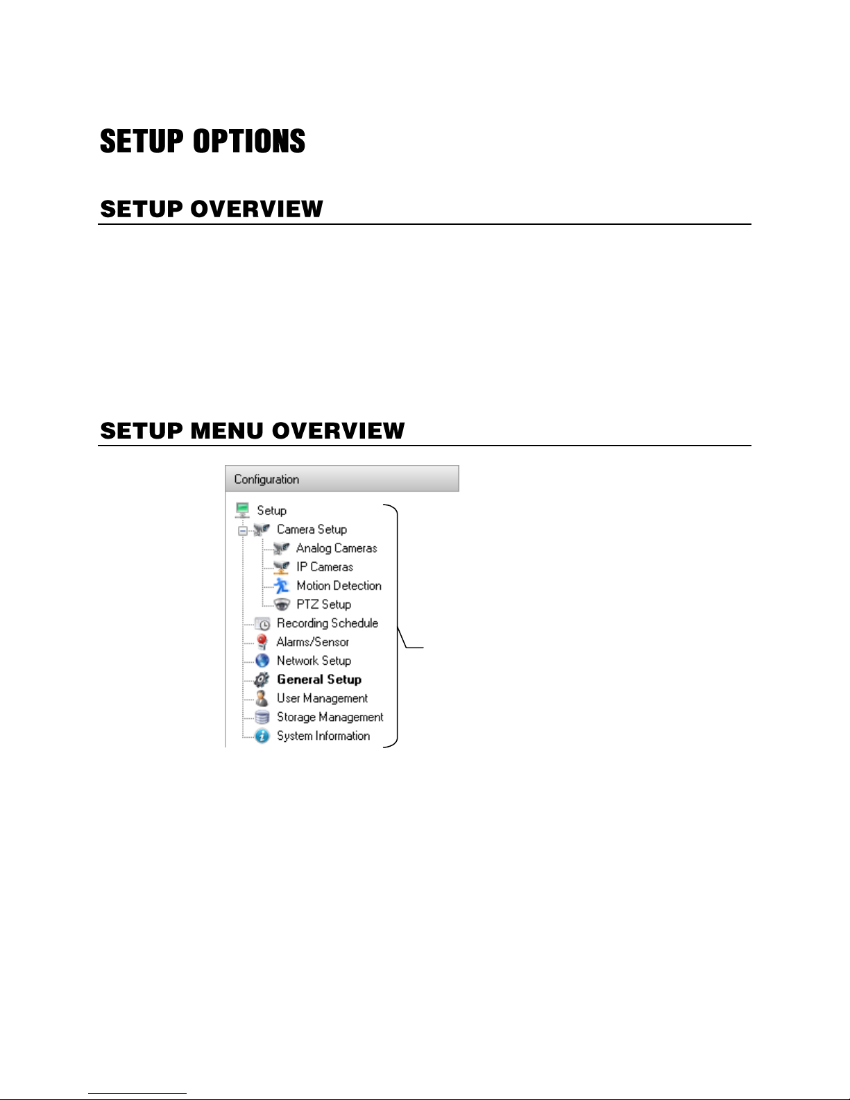
Setup Options .......................................................................................................................................................... 31
Setup Overview ............................................................................................................................................. 31
Setup Menu Overview.................................................................................................................................... 31
8

Analog Camera Setup.................................................................................................................................... 32
Set Up New Camera ........................................................................................................................ 32
Frame Setup .................................................................................................................................................. 33
Standard Models ............................................................................................................................. 33
H-Series Models .............................................................................................................................. 34
240E Models.................................................................................................................................... 34
Maximum FPS Table ....................................................................................................................... 35
Network Camera Setup.................................................................................................................................. 36
Connecting a Network Device ......................................................................................................... 36
Assigning Dual Streams .................................................................................................................. 38
Assigning Audio Channels to a Network Device .............................................................................. 38
Camera Status and Information ....................................................................................................... 39
NVR Registration ............................................................................................................................. 40
Unlocking Additional Network Devices ............................................................................................ 41
PTZ Camera Setup ................................................................................................................................................. 42
Enabling an Analog PTZ Camera .................................................................................................... 42
Enabling an IP PTZ Camera ............................................................................................................ 42
Using the Graphical PTZ Controller ................................................................................................. 43
Motion DETECTION Setup ............................................................................................................................ 44
Create a Motion Area ...................................................................................................................... 44
Enable Sabotage Detection ............................................................................................................. 45
Etc. .................................................................................................................................................. 45
General Setup ................................................................................................................................................ 46
Audio ............................................................................................................................................... 46
Display ............................................................................................................................................. 47
General ............................................................................................................................................ 48
Sequencing...................................................................................................................................... 49
POS ................................................................................................................................................. 50
Alarms / Sensor ............................................................................................................................................. 52
Alarms ............................................................................................................................................. 52
Sensors ........................................................................................................................................... 52
Relays ............................................................................................................................................. 54
Recording Schedule....................................................................................................................................... 55
Default Schedules ........................................................................................................................... 55
Day of the Week .............................................................................................................................. 56
Creating a Recording Schedule (Example) ..................................................................................... 56
Creating a Sensor Schedule (Example) .......................................................................................... 58
Special Day Schedule ..................................................................................................................... 59
Alarm Options .................................................................................................................................. 60
Setting a Restart Schedule .............................................................................................................. 61
Network Setup ............................................................................................................................................... 62
User Management ......................................................................................................................................... 63
Changing the Administrator Password ............................................................................................ 64
Storage Management .................................................................................................................................... 65
Status Check / Email ....................................................................................................................... 65
SMART Information ......................................................................................................................... 68
Data Management ........................................................................................................................... 69
System Information ........................................................................................................................................ 70
Basic Information ............................................................................................................................. 70
Log Files .......................................................................................................................................... 72
Upgrade Information ........................................................................................................................ 74
Search ..................................................................................................................................................................... 76
Search Overview ........................................................................................................................................... 76
Play Controls ................................................................................................................................... 76
32865AC 9

Adjust the Brightness of an Image ................................................................................................... 77
Zooming in on an Image .................................................................................................................. 77
Zooming in on a Portion of an Image ............................................................................................... 77
Open Video from a Saved Location ................................................................................................. 77
Sync ................................................................................................................................................ 77
Clean Image .................................................................................................................................... 77
Instant Recording ........................................................................................................................................... 78
Activate Instant Recording ................................ ............................................................................... 78
Searching ‘Instant Recorded’ Video ................................................................................................ 78
Performing a Basic Search ............................................................................................................................ 78
Printing an Image ........................................................................................................................................... 78
Daylight SavIng Time ..................................................................................................................................... 79
Export Image or Video Files ........................................................................................................................... 80
Bookmarks....................................................................................................................................... 81
Clip Backup ..................................................................................................................................... 82
Index Search .................................................................................................................................................. 83
Performing an Index Search ............................................................................................................ 83
Index Search Results Display .......................................................................................................... 83
Preview Search .............................................................................................................................................. 84
Performing a Preview Search .......................................................................................................... 85
Status Search ................................................................................................................................................ 85
Performing a Status Search............................................................................................................. 85
Object Search ................................................................................................................................................ 86
Performing an Object Search .......................................................................................................... 86
Motion Search ................................................................................................................................................ 87
Performing a Motion Search ............................................................................................................ 87
Audio Playback .............................................................................................................................................. 87
Search in Live ................................................................................................................................................ 88
Pan / tilt / zoom ........................................................................................................................................................ 89
Pan /Tilt / Zoom Overview .............................................................................................................................. 89
Basic PTZ Configuration .................................................................................................................. 89
Advanced PTZ Setup ..................................................................................................................................... 90
General ............................................................................................................................................ 90
PTZ Presets/Tours .......................................................................................................................... 91
Accessing PTZ Menus ................................................................................................................................... 91
Controlling a PTZ Camera ............................................................................................................................. 91
Using the Graphical PTZ Controller ................................................................................................. 92
Using the On-Screen Compass ....................................................................................................... 92
Understanding Tours ....................................................................................................................... 93
PTZ Tour Schedule ......................................................................................................................... 93
backing up Video Data ............................................................................................................................................ 94
Backup Overview ........................................................................................................................................... 94
Nero® Express ................................................................................................................................. 94
General Backup Overview ............................................................................................................... 95
Clip Backup Overview ..................................................................................................................... 96
Scheduled Backup Overview ........................................................................................................... 97
lan / isdn / pstn connections ................................................................................................................................ .... 99
LAN Overview ................................................................................................................................................ 99
Connecting to a LAN Using TCP/IP ............................................................................................................... 99
10

Configuring TCP/IP Settings ............................................................................................................ 99
Active Directory Integration ................................................................................................................................... 100
Features ....................................................................................................................................................... 100
Installing Active Directory ............................................................................................................................. 100
Web Viewer ........................................................................................................................................................... 102
Web Viewer Overview.................................................................................................................................. 102
Configuring the Recorder for Remote Connection ......................................................................... 103
Connecting to a Recorder Using Web Viewer ............................................................................... 103
Closing the Web Viewer ................................................................................................................ 103
Included Software Setup ....................................................................................................................................... 104
MDVR Overview .......................................................................................................................................... 104
Emergency Agent Overview ........................................................................................................................ 104
Configuring the Recorder .............................................................................................................. 104
Configuring the Client PC .............................................................................................................. 105
Setup Window ............................................................................................................................... 105
Emergency Agent Window ............................................................................................................ 106
Search Alarm Window ................................................................................................................... 107
Remote Software Overview ......................................................................................................................... 108
Remote Software Setup ................................................................................................................ 109
Digital Verifier Overview ............................................................................................................................... 111
Installing the Digital Verifier ........................................................................................................... 111
Using the Digital Verifier ................................................................................................................ 111
Backup Viewer Overview ............................................................................................................................. 112
Installing Backup Viewer ............................................................................................................... 112
Loading Video from DVD or Hard Drive ......................................................................................... 112
RADIUS Overview ....................................................................................................................................... 113
Connecting to a Recorder .............................................................................................................. 113
32865AC 11

This manual is a setup and maintenance guide that can be used for reference when setting up the recorder and for
troubleshooting when a problem occurs. Only authorized personnel should attempt to repair this unit.
OpenEye reserves the right to make changes to the NVRs represented by this manual without notice.
The following text and symbols mark special messages throughout this guide:
Text set off in this manner indicates information that is necessary for proper operation of the
product.
Text set off in this manner indicates information that may be helpful.
Only authorized technicians trained by OpenEye should attempt to repair this recorder. All
troubleshooting and repair procedures are to be used for reference and minor repair only.
Due to the complexity of the individual components and subassemblies, no one should
attempt to make repairs at the component level or to make modifications to any printed
wiring board. Improper repairs can create a safety hazard, and any indications of
component replacement or printed wiring board modifications may void any warranty
To reduce the risk of electrical shock or damage to the equipment:
Do not disable the power grounding plug. The grounding plug is an important safety
feature.
Plug the power cord into a grounded (earthed) electrical outlet that is easily
accessible at all times.
Disconnect the power from the computer by unplugging the power cord either from
the electrical outlet or the computer.
To properly ventilate your system, you must provide at least 3 inches (7.6 cm) of clearance
at the front and back of the recorder.
12

SHM
SH
OpenEye SHM / SH NVR recorders are servers that perform as High Definition Digital Recorders. By
utilizing the many features of a computer, including processing power, storage capacity, graphics
compression, and security features, hybrid recorders more powerful than the analog recorders of the
past.
The OpenEye server software is pre-configured for fast and seamless integration within your existing IT
infrastructure. Designed around a Microsoft® Windows 7 Embedded operating system, the server
software offers unparalleled stability, security, and ease of use. Accordingly, your security investment
has never been easier to maintain. Multiple users can simultaneously connect through any network
connection for instantaneous live viewing, search, and off-site video storage. Users can also connect
remotely via the Internet. This powerful software enables you to establish recording schedules, create
motion detection zones, use PTZ controls, and configure alarm inputs and outputs for each of the
system's cameras. New advancements in OpenEye Server Software make it even easier to search,
index, and export video files.
The OpenEye NVR is high performance security product ready to meet today’s security demands.
32865AC 13

OpenEye SHM / SH NVRs include the following new features:
Optimized and Designed for Microsoft® Windows 7 Embedded®
Up to 16 Camera Inputs
Supports up to 4 Relay Outputs on Alarm Activation
Supports up to 16 Sensor Inputs for Alarm Control
Remote System Operation & Configuration
Supports Multiple Simultaneous Remote Connections
PAN / TILT / ZOOM Controls
Simultaneous Video Search, Playback and Backup
Video Indexes for Easy Searching
Multiple Levels of Security Access
Up to 16 Looping Outputs
Up to 1 Composite Outputs
Up to 32 Network Recording Channels
Up to 16 Audio Inputs
High Performance, Durable, Rack mount Case
Output the Video to a NTSC/PAL Display
Up to 12 Terabytes internal storage
Digital Signature Support
Continuous, Motion Detection, Alarm, Pre-Alarm, and Scheduled Recording Modes
Hardware Watchdog
Recording Resolution 720x480 / 720x240 / 360x240 NTSC / 720x576 / 720x288 / 360x288
PAL
14
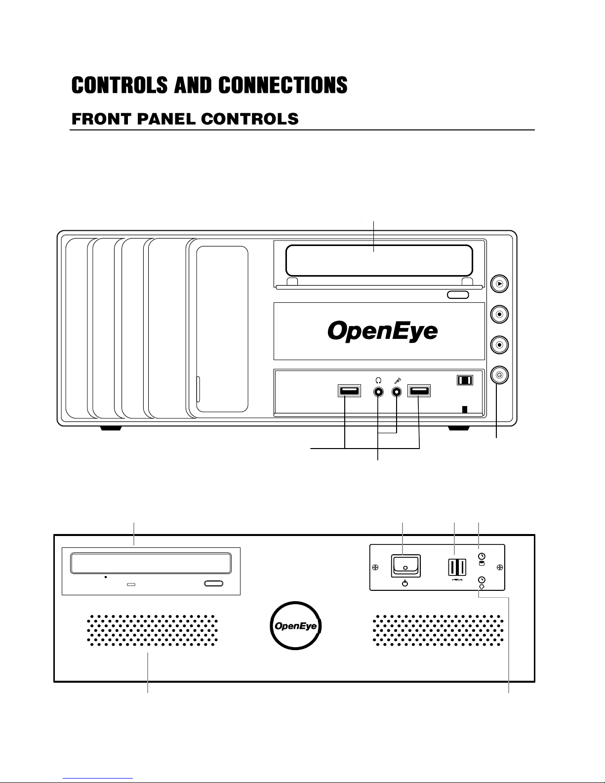
SHM
USB
ports
Power
button
Audio
DVD±RW
DVD±RW Drive
Cooling fan intake
Hard drive activity LED
Power LED
USB portsPower switch
The front panel of the recorder contains the devices that will be commonly used for data removal,
retrieval, and backup replacement. The most common components and buttons are shown below.
SH
32865AC 15

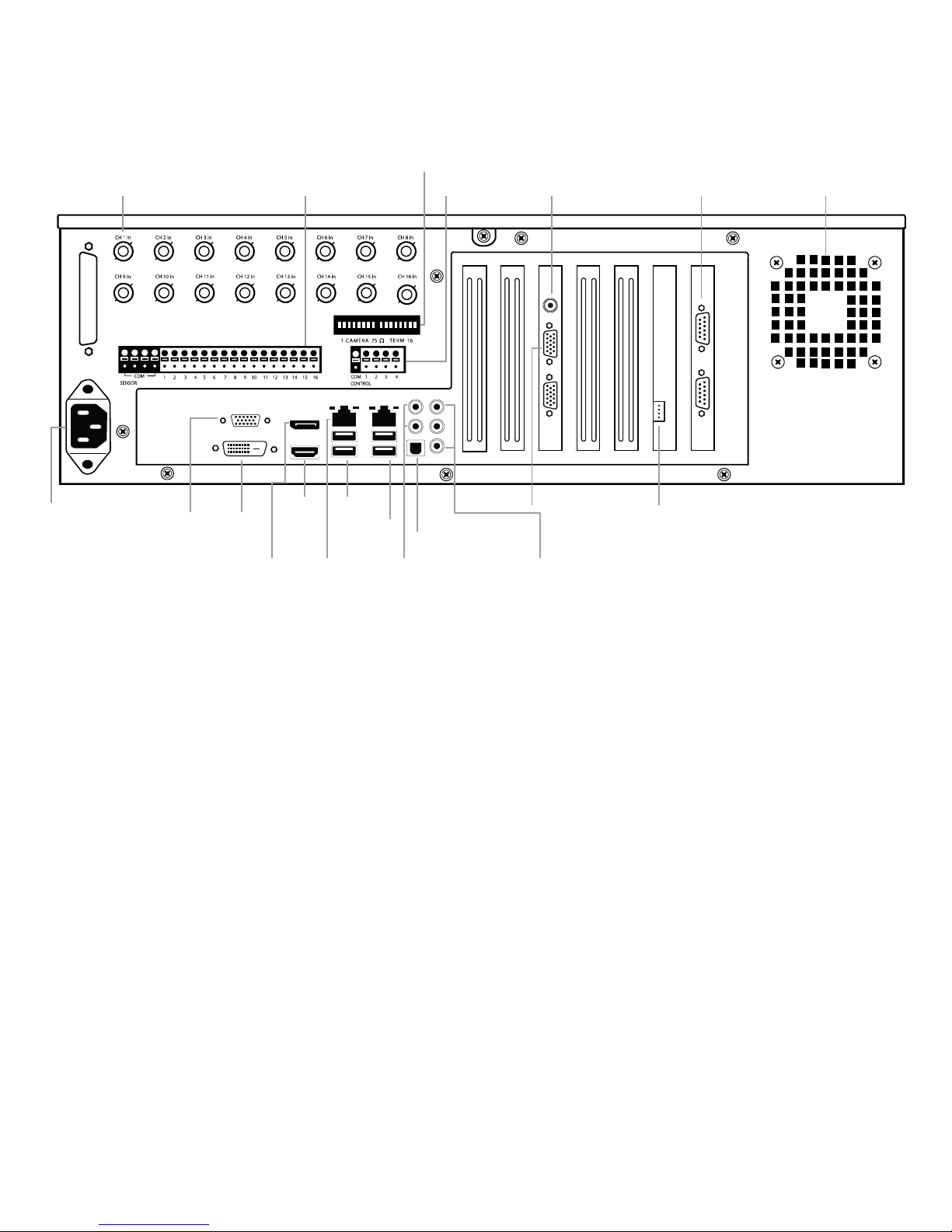
The rear panel of the recorder contains the connectors used to attach cameras, sensors, and relays to
AC
PTZ
Line in – line level
Speaker out
Microphone in – not
Optica
l
HDMI
Networ
US
DVI-I
BNC looping output cable
5.1 surround
RCA video
VGA
Video in
Audio
the recorder. Below are diagrams that outline the location and description of each connector.
SHM
16
SH
AC power
Looping output termination
Video input (BNC) Sensor inputs Control outputs Cooling fan
Optical output
5.1 Surround sound
HDMIVGA
Network
Line in – line level
Speaker out
Microphone in – not used
USB 2.0
USB 3.0
DVI-D
Display
port
Audio inputVideo output
PTZLooping output
32865AC 17
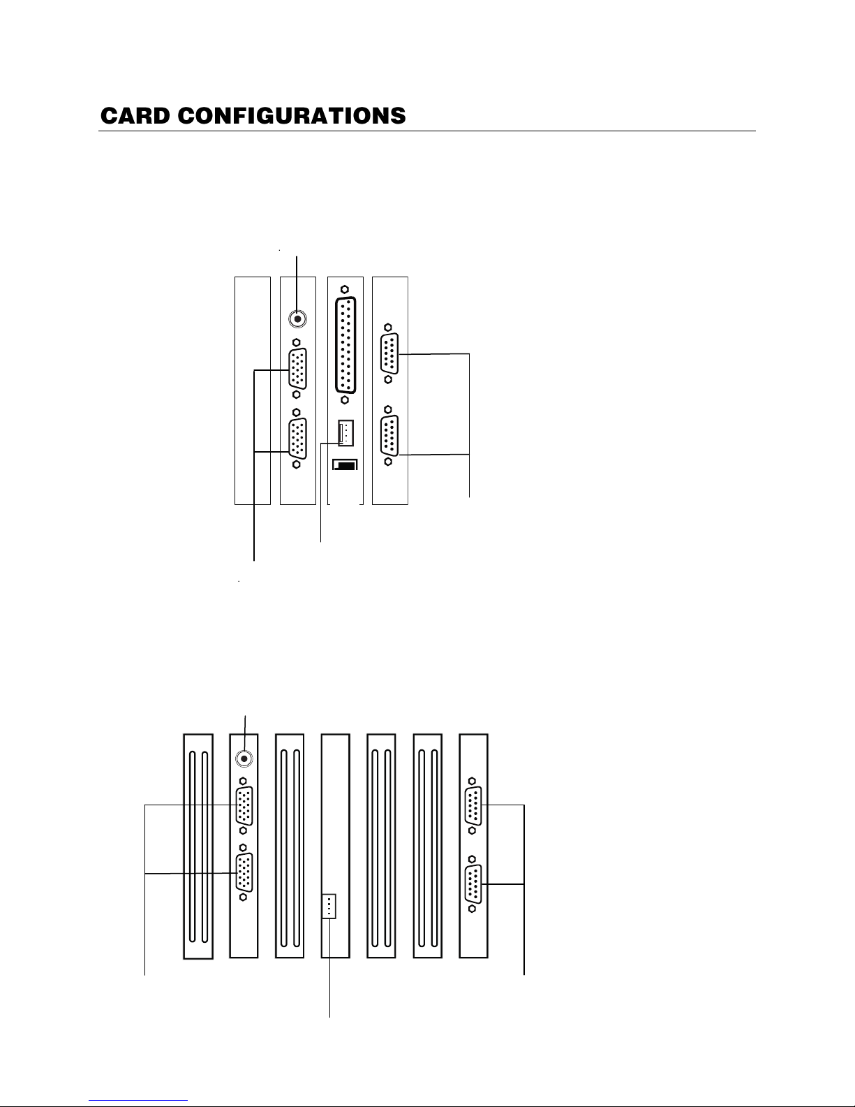
RCA video
PTZ
Audio
Video
Audio
Looping output
PTZ
RCA video out
240 PPS 16 Channel
480 PPS 16 Channel
18

OpenEye recorders come with a mouse, keyboard and selected software and cables. Identify the
Case key
Mouse
Keyboard
Repair disc/ Software disc
Power cable
PTZ adapter
HDMI to DVI-D adapter
Rack mount kit
following components to make sure everything has been properly included with the new NVR. If any of
the following items are missing, contact the dealer to arrange a replacement.
32865AC 19

To attach the keyboard to the recorder, plug the end of the Keyboard into a USB port located on the
Right Button
Scroll Button / Third
Left Button
back of the machine.
To attach the mouse to the recorder, plug the end of the mouse into a USB port located on the back of
the machine.
The mouse uses a cursor called a pointer. Pointers come in many different shapes but are most
commonly shaped like an arrow.
The mouse has two buttons: a left button and a right button. Quickly pressing and releasing one of
these buttons is called clicking. Sometimes you will need to double-click – or click the same button twice
quickly.
In this manual:
Click means to position the mouse cursor over an item and to single click the left button.
Right click means to position the mouse cursor over an item and to single click the right button.
Double-click means to position the mouse cursor over an item and to click the left button twice.
Select means to position the mouse cursor over a radio button, checkbox, or list item and click on it.
The scroll wheel in between the two buttons is used for added navigation functionality. By moving the
wheel with index finger (scrolling), quickly move through multiple pages, lines, or windows. The wheel
may also function as a third button allowing the user to quickly click or double-click an icon or a selected
item.
20
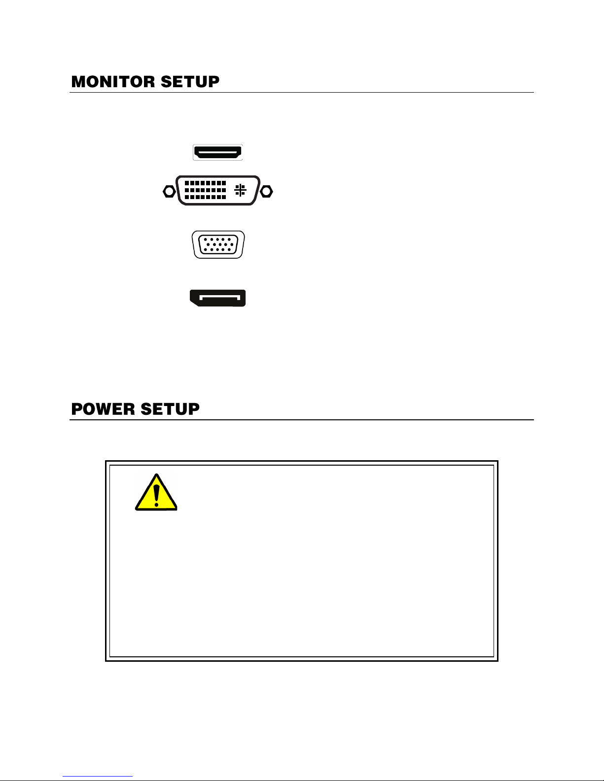
The recorder has the following connections available to attach a monitor.
HDMI
Output
To TV /
Digital
Monitor
DVI -I
Output
To TV /
Digital
Monitor
DVI to
SVGA
Adapter
Connect
adapter to
DVI output to
connect an
analog VGA
Monitor.
Display
Port
Output
To Digital
Monitor
WARNING:
To reduce the risk of electrical shock or damage to the
equipment:
Do not disable the power grounding plug.
The grounding plug is an important safety feature.
If the electrical plug you are using does not have a ground plug
receptacle contact a licensed electrician to have it replaced with
a grounded electrical outlet.
Plug the power cord into a grounded (earthed) electrical outlet
that is easily accessible at all times.
Disconnect the power from the computer by unplugging the
power cord either from the electrical outlet or the computer.
Attach the monitor or monitors to the rear of the recorder using the cable supplied by the monitor
manufacturer. Refer to the monitor manual for detailed information on how to setup and use it.
Note The monitor must be capable of having a screen resolution of 1024 x 768 and display
colors of at least 32 Bit
32865AC 21

Connecting a PTZ Camera
RS-422
Signal Line (+)
Signal Line (-)
Setting up a PTZ Camera is simple. The recorder comes preassembled with an internal PTZ adapter.
The cabling may be run up to 4,000 ft using 22 Gauge Twisted Pair.
It is important to understand how the PTZ connects to the recorder. The recorder outputs an RS-232
signal and converts in to an RS-485 signal which is then sent to the PTZ camera.
1. Locate the PTZ adapter cable
2. Connect the wires of the PTZ adapter to the PTZ camera.
The yellow wire should connect to the RX+ on the camera
and the orange wire should connect to the RX-.
3. Connect the other end of the adapter to the XVR unit as
shown.
4. Assign the PTZ camera an ID number in PTZ Setup that
coincides with the number assigned to the camera. This is
normally done utilizing a dip-switch configuration method
on the addressable dome.
Example: If the camera is plugged into input number 5,
set the PTZ unit to ID number.
22

Once the cables and adapters have been properly connected it is time to turn on the power. To turn on
the power follow these steps:
1. Turn on the monitor and any external peripherals (ex. Printers, External Storage Devices, etc.)
connected to the recorder.
2. Turn on the Secondary Power Switch located in the rear of the recorder.
3. Turn on the main power switch located on the front of the recorder.
The recorder will run a series of self-tests. After two or three minutes a series of messages may be
displayed as the various hardware and software subsystems are activated. Under normal
circumstances you should not be asked to respond to these messages. If you are asked to respond to
the messages (adding a Printer, Monitor, etc for the first time) follow the instructions carefully.
After this finishes, the OpenEye recorder software should load automatically and bring you to the main
screen.
To turn off the recorder, select the Exit button on the main screen and select Power Off. The recorder
will safely shutdown, it may take several minutes to shut down completely.
Always be sure to follow the proper procedures when turning off the power. NEVER
disconnect the power to the recorder while it is still running or in the process of shutting
down. Doing so can cause data loss, file corruption, system instability and hardware failure.
32865AC 23
1. Exit to Windows by clicking Exit on the Display screen, and then clicking Restart in Windows
Mode.
5. Click OK.
6. Click Start ( ), and then click Control Panel.
7. Click Date and Time, and then click Change Date and Time.
8. Adjust the Date and Time.
9. When finished, click OK, and then click OK again.
10. Close any open windows.
11. Click Start, and then click Shutdown.
12. Select Restart.
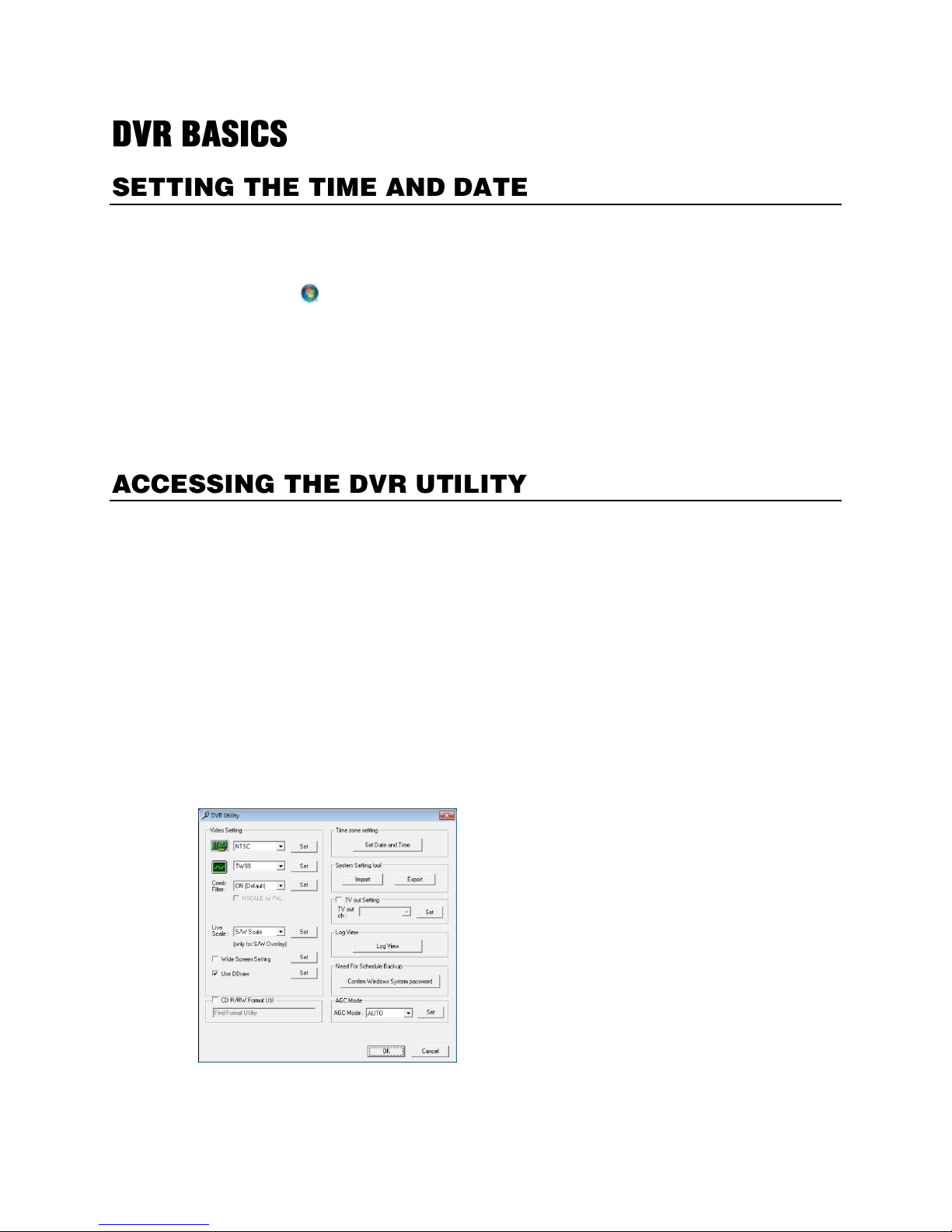
Exporting Settings
Exporting settings can help configure multiple recorders quickly or reconfigure a unit that has been reset
to factory defaults. Some things must be kept in mind when using this feature.
You cannot use this function on:
Recorders that are different models.
When upgrading from certain software versions. (This feature cannot be used when upgrading
from v4.x to v5.x)
1. Exit to Windows by clicking Exit on the Display screen, selecting Restart in Windows Mode, and
then clicking OK.
2. Click Start > All Programs > OpenEye > vFormat.
3. Click Export in the System Setting Tool section.
4. Select a location to save the settings file, and then click Save. The DVR Utility will export the
settings and automatically close.
24

Importing Recorder Settings
1. Exit to Windows by clicking Exit on the Display screen and then clicking Restart in Windows
Mode.
2. Click Start > All Programs > OpenEye > vFormat.
3. Click Import in the System Setting Tool section.
4. Select the location of the settings file to import, and then click Open.
5. Click Yes to import the data file.
32865AC 25
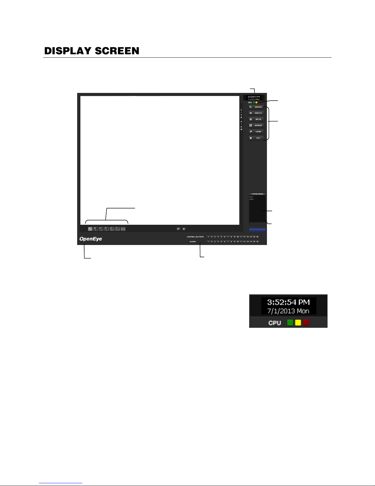
The Display screen appears whenever the recorder starts. Familiarize yourself with the buttons and
Opens:
Search
PTZ Controller
Setup
Backup
Login
Exit
Current Date / Time
Sensor Status
Relay Outputs
Screen Division buttons
Connected
Users
User Details
CPU meter
features on the Display screen, since this is the default screen for your recorder software.
CPU Meter
Use the CPU meter to monitor the system resources of your recorder.
GREEN - System configuration OK
YELLOW - Caution; evaluate system configuration and
consider decreasing system load
RED - System configuration has been exceeded which
may affect stability; decrease system load or upgrade
system with CPU performance package.
26

Live Camera Options
Right-click a camera on the Display screen to display these options:
Full Screen – Expand the camera
window to the full size of the
screen.
Instant Recording – Begin
Instant Recording for the selected
camera channel.
Search In Live – Rewind or fast-
forward video from that camera at
the present date and time.
360 Setup – Configure settings
for a 360 camera.
Enable 360 Camera – Enable the use of a 360 camera.
e-PTZ – Use the digital PTZ function on a 360 camera
View type – Select the view for a 360 camera
Mount Type – Select the type of mount that matches the location of your 360 camera.
Projection type – Dewarp your 360 camera image in Spherical or Flat view (Panogenics
cameras only)
Oncam SDK – Select to dewarp video footage from an Oncam 360 IP camera
Panamorph SDK – Select to dewarp video footage from an Immervision 360 camera
Panogenics SDK – Select to dewarp video footage from an AMG Panogenics 360 camera
Note 360 Setup, Enable 360 Camera, e-PTZ, View Type, Mount Type, Projection Type, all require
a 360 camera to function. If you do not have a 360 camera, ignore these functions.
32865AC 27
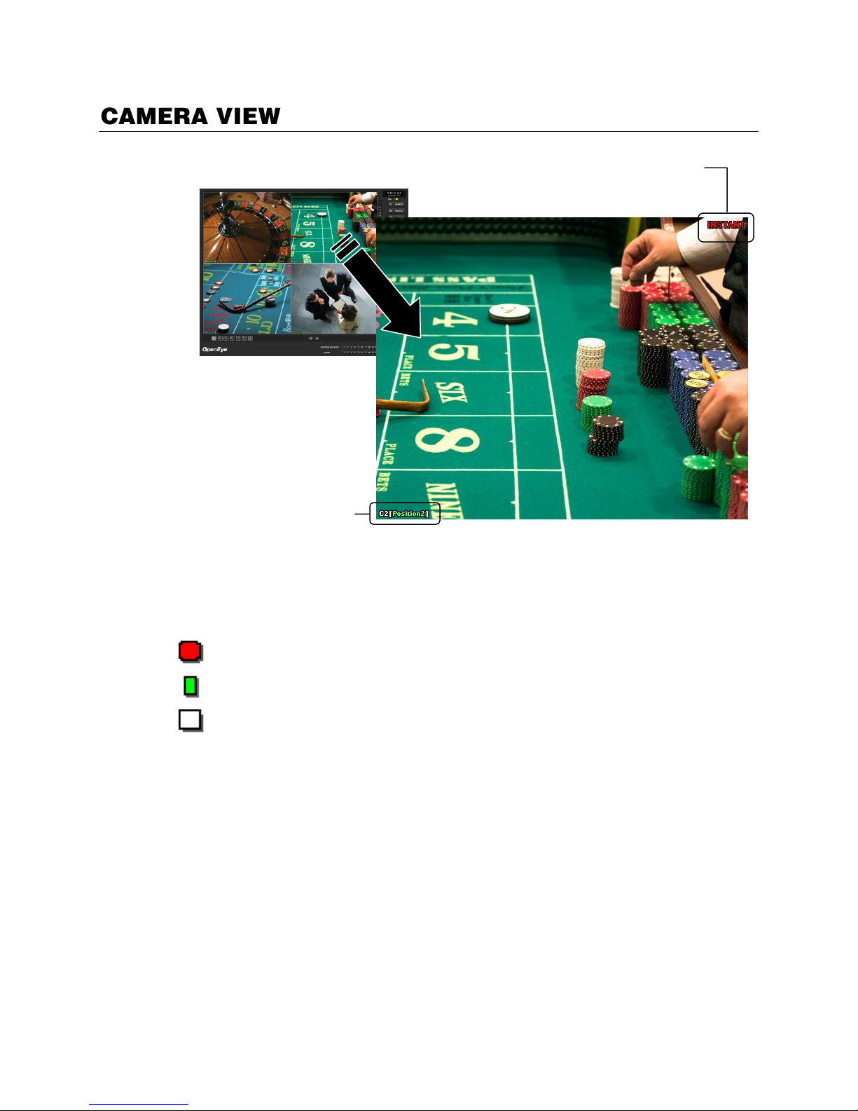
Recording Status Indicator
Recording
Displayed when the camera is currently being recorded to the recorder.
Motion Detection
Displayed when a camera (set up for motion detection) detects motion.
Display
Displayed when the camera is currently not being recorded to the recorder.
I
Recording Status
Camera Number and Name
The recording status for each camera is displayed in the upper right corner on the Video Display Area.
There are three different recording statuses.
Special Recording
There are two types of Special Recording. Text is displayed on the camera display area, indicating what
type of Special Recording is activated.
SENSOR
Sensor is displayed when a sensor associated with the camera is activated.
INSTANT
Instant Recording is a manual activation of the recording for the selected camera. Regardless of the
recording method, Instant Recording will start the camera recording and also flag the video for future
searches using the Index Search feature. INSTANT is displayed when a user activates the instant
recording option. Double right-click the video display to activate and deactivate the Instant Recording
option.
28
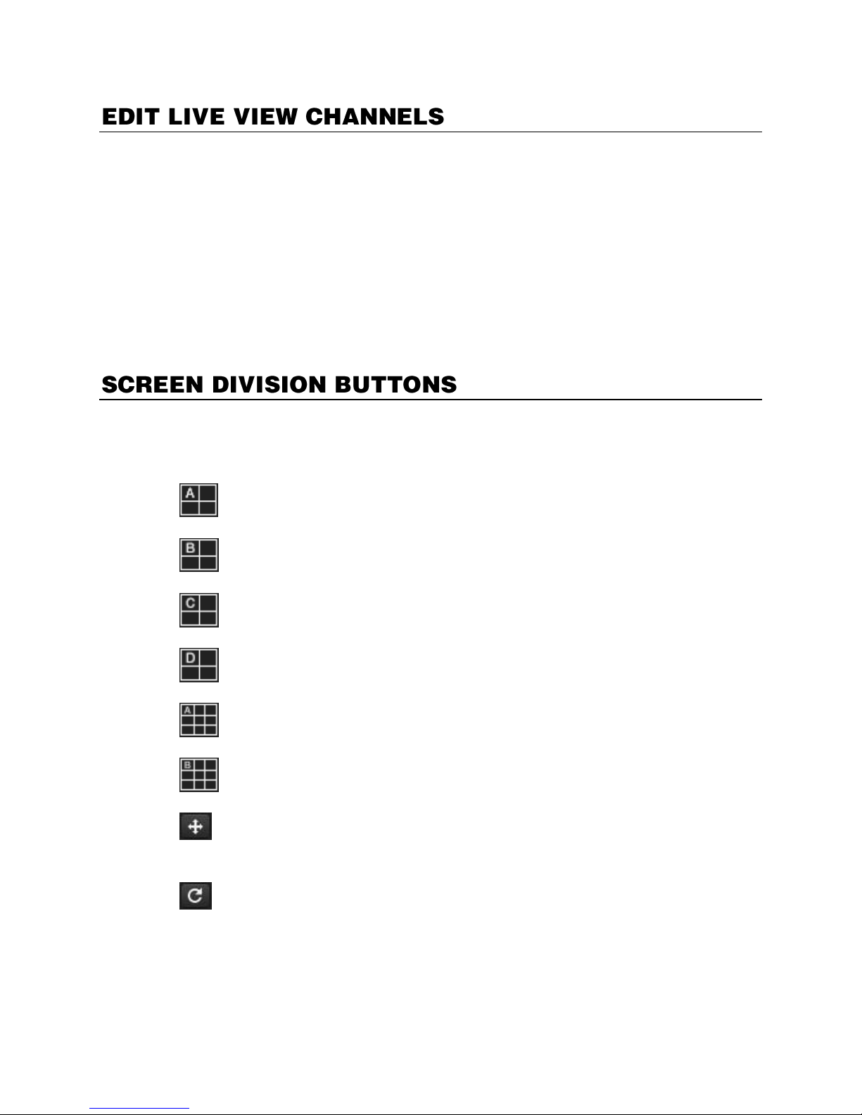
By default, the recorder displays live video from four IP cameras at one time on the local server. This
1st Four Cameras View – Displays cameras 1-4 in the Video Display Area. To return to a
different Multi-Camera View, select a different Screen Division option from the Screen Division
menu.
2nd Four Cameras View – Displays cameras 5-8 in the Video Display Area. To return to a
different Multi-Camera View, select a different Screen Division option from the Screen Division
menu.
3rd Four Cameras View – Displays cameras 9-12 in the Video Display Area. To return to a
different Multi-Camera View, select a different Screen Division option from the Screen Division
menu.
4th Four Cameras View – Displays cameras 13-16 in the Video Display Area. To return to a
different Multi-Camera View, select a different Screen Division option from the Screen Division
menu.
1st Nine Cameras View – Displays cameras 1-9 in the Video Display Area. To return to a
different Multi-Camera View, select a different Screen Division option from the Screen Division
menu.
2nd Nine Cameras View – Displays cameras 10-18 in the Video Display Area. To return to a
different Multi-Camera View, select a different Screen Division option from the Screen Division
menu.
Full Screen – The Full Screen Option allows you to view the Video Display Area using the entire
viewable area on the monitor. When this is selected, no menu options are visible. You can
activate the Full Screen Option by clicking on the Full Screen button within the Screen Division
menu. You can deactivate Full Screen mode by right clicking on the screen.
Auto Sequence – Sequences through the Screen Divisions sets. For example, selecting the 1A
and then the Loop button will sequence through 1A, 2A, 3A, 4A and then repeat.
protects the processor resources for recording data. You can change your settings to allow 16 IP
channels to be displayed in the live view. Be aware that displaying 16 channels of live IP video is
resource-intensive and may dramatically impact system performance.
To enable the recorder to view 16 channels of live video:
1. Click Exit on the Display screen, and then select Restart in Windows Mode.
2. Double-click the Edit Live View Channels icon on the desktop.
3. Click Yes, and then click OK.
4. The live view display will switch to 16 channel mode. To return the recorder to 4 channel mode,
repeat steps 2 and 3.
5. Double-click OpenEye Server to restart the recorder software.
Note When viewing live video from Network Cameras, only 4CH will display at one time. If more
live view channels are required on the local server, see the Edit Live View Channels
instructions.
32865AC 29
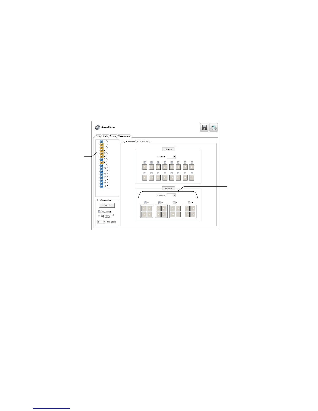
Custom Live View Divisions
Division Group
Channel
List
Customize your Display screen by changing the order of the cameras. Each screen division can be
individually customized but a camera can only be displayed once in each group view. All selected
screen divisions will be shown when AutoSequence is enabled on the Display screen. Be sure to clear
any screen division you do not want to be displayed during AutoSequence viewing.
Create custom live view divisions:
1. On the Display screen, click Setup, and then click General Setup.
2. Click theSequencing tab.
3. Drag and drop cameras from the Channel List to the desired location within the Division Group.
4. Select the screen intervals you want to display in each division area.
5. Set the Interval time (in seconds). This determines how long each sequence screen will appear on
the Live display.
6. To save your settings, click Apply.
30
Setup Options
The Setup options allow you to optimize your recorder by adjusting things like camera names, restart
schedules, recording schedules and more.
Recording Schedules – Increase the amount of useful recorded video that is saved on the
recorder by optimizing the recording schedule. Optimize the type of recording by adding
motion detection to this as well, again increasing the amount of useful video.
Camera Naming – Name each camera so the location can be easily identified and include any
other pertinent information that may be helpful when viewing it on the Video Display Area.
Configure Network Cameras – Connect to and configure cameras that are available on the
network the recorder is connected to.
32865AC 31
 Loading...