

Page 1
1 Channel Network Encoder
User Manual
Model
NE-VS201
www.openeye.net
Page 2

2
Page 3

1 Channel Network Encoder (NE-VS201)
User Manual
Manual Edition 30145AB – JUNE 2012
©2000-2012, OPENEYE
All Rights Reserved.
No part of this documentation may be reproduced in any means, electronic or mechanical, for any
purpose, except as expressed in the Software License Agreement. OpenEye shall not be liable for
technical or editorial errors or omissions contained herein. The information in this document is
subject to change without notice.
The information in this publication is provided “as is” without warranty of any kind. The entire risk
arising out of the use of this information remains with recipient. In no event shall OPENEYE be
liable for any direct, consequential, incidental, special, punitive, or other damages whatsoever
(including without limitation, damages for loss of business profits, business interruption or loss of
business information), even if OPENEYE has been advised of the possibility of such damages and
whether in an action or con tra ct or tort, inc lud ing neg lige nce .
This documentation is copyrighted. All other rights are reserved to OPENEYE. OPENEYE, and
OpenEye, are registered trademarks of OPENEYE in the United States and elsewhere; Windows,
and Windows XP Embedded are registered trademarks of Microsoft Corporation. All other brand
and product names are trademarks or registered trademarks of the respective owners.
OPENEYE
Liberty Lake, WA ● U.S.A.
30145AB 3
Page 4

Important Safeguards
1. Read Instructions
Read all of the safety and operating instructions before using the product.
2. Retain Instructions
Save these instructions for future reference.
3. Attachments / Accessories
Do not use attachments or accessories unless recommended by the appliance
manufacturer as they may cause hazards, damage product and void warranty.
4. Installation
Do not place or mount this product in or on an unstable or improperly supported
location. Improperly installed product may fall, causing serious injury to a child or
adult, and damage to the product. Use only with a mounting device recommended by
the manufacturer, or sold with the product. To insure proper mounting, follow the
manufacturer's instructio ns an d use only mounting accessories recommended by
manufacturer.
5. Power source
This product should be operated only from the type of power source indicated on the
marking label.
Precautions
Operating
• Before using, make sure power supply and other s are properly connected.
• While operating, if any abnormal condition or malfunction is observed, stop using the
camera immediately and then contact your local dealer.
Handling
• Do not disassemble or tamper with parts ins ide the ca mera.
• Do not drop or subject the camera to shock and vibration as this can damage camera.
• Do not block the cooling holes on the bracket. This camera has a cooling fan inside
the housing. Blocking the cooling holes will cause heat to build up and cause
malfunction.
• Care must be taken when you clean the clear dome cover. Scratches and dust will
ruin the image quality of your camera. Do not use strong or abrasive detergent s
when cleaning the camera body. Use a dry cloth to clean the camera when it is dirty.
In case the dirt is hard to remove, use a mild detergent and wipe the camera gently.
4
Page 5

Installation and Storage
• Install electricity wir ing carefully. Please note that input electricity to the unit is at
tolerance of DC 12V 10%.
• Do not install the camera in areas of extreme temperatures in excess of the allowable
range. (-50°C ~50°C / -58°F ~ 122°F)
• Avoid installing i n humid or dusty places. The relative humidity must be below 90%.
• Avoid installing in places where radiation is present.
• Avoid installing in places where there are strong magnetic fields and electric signals.
• Avoid installing in places where the encoder would be subject to strong vibrations.
Regulation
This device complies with Part 15 of the FCC Rules. Operation is subject to the
following two conditions: (1) this device may not cause harmful interference, and (2)
this device must accept any interference received, including interference that may
cause undesired operation.
This symbol on the product or on its packaging indicates that this product
shall not be treated as household waste in acc orda nce w ith Dir ective
2002/96/EC. Instead it shall be handed over to the applicable collection
point for the recycling of electrical and electronic equipment. By proper
waste handling of this product you ensure that it has no negative
consequences for the environment and hu man health, which could
otherwise be caused if this product is thrown into the garbage bin. The
recycling of materials will help to conserve natural resource s.
For more details information about recycl ing of th is prod uct, please
contact your local city office, your household waste disposal service or
the shop where you purchased the product.
Compliance is evidenced by written declaration from our suppliers,
assuring that any potential trace contamination levels of restricted
substances are below the maximum level set by EU Directive
2002/95/EC, or are exempted due to their application.
30145AB 5
Page 6
CAUTION: TO REDUCE THE RISK OF ELECTRIC SHOCK,
DO NOT REMOVE COVER (OR BACK).
NO USER-SERVICEABLE PARTS INSIDE.
REFER SERVICI NG TO QUA LIF IED SERVICE PERSONNEL.
CAUTION
RISK OF ELECTRI C S HOCK
DO NOT OPEN
Warning
DANGEROUS HIGH VOLTAGES ARE PRESENT INSIDE THE ENCLOSURE.
DO NOT OPEN THE HOUSING.
REFER SERVICING TO QUALIFIED PERSONNEL ONLY.
Caution
6
Page 7

Standard Warranty
OpenEye warrants all new products to be free from defects in workmanship and material
under normal use for a period of two years after the date of purchase. Any defective
product that falls under this warranty will, at OpenEye's discretion, be repaired or replaced
at no additional charge. OpenEye may elect to replace defective products with new or
factory reconditioned products of equal or greater value. Repairs made necessary by
reason of misuse, alteration, normal wear, or accident are not covered under this
warranty.
Exceptions to this are listed below:
• Three Years on all Digital Recorders
• Three years on all fixed cameras
All products shall be covered by a one year advance replacement warranty*.
OpenEye will warrant all otherwise out of warranty replacement parts and repairs for 90
days from the date of OpenEye shipment.
The above warranty is the sole warranty made by OpenEye and is in lieu of all other
warranties by OpenEye express and implied, including without limitation the warranties of
merchantability and fitness for a particular purpose. Under no circumstances will OpenEye
be liable for any consequential, incidental, special or exemplary damages arising out of or
connected with the sale, delivery, use or performance of the product, even if OpenEye is
apprised of the likelihood of such damages occurring. In no event shall OpenEye liability
exceed the purchase price of the product.
This warranty gives you specific legal rights and you may also have other rights which
vary from state to state or country to country.
*Requires corresponding security deposit. Advanced Replacement limited to components
only outside of the USA and Canada.
For the most up to date information visit www.openeye.net
30145AB 7
Page 8

TABLE OF CONTENTS
Table of Contents ..................................................................................... 8
Introduction ............................................................................................ 11
Overview ....................................................................................................................... 11
Product Features ...................................................................................................... 11
Getting Started ....................................................................................... 12
Package Contents ........................................................................................................ 12
Setup and Cable Connection ........................................................................................ 13
Video Server Setup .................................................................................................. 13
Dimensions........................................................................................................... 13
Connector Definition ............................................................................................. 14
Front................................................................................................................. 14
Rear ................................................................................................................. 15
Video Server Cable Definition and Requirements .................................................... 16
Network Cable ...................................................................................................... 16
Power Connection ................................................................................................ 16
Ethernet Cable Connection .................................................................................. 16
Camera Finder ........................................................................................ 17
OpenEye IP Finder ....................................................................................................... 17
Finding IP Devices .................................................................................................... 17
Default Username and Password ........................................................................ 17
Changing the Network Type ..................................................................................... 18
Setup & Configuration ........................................................................... 18
Connecting to the Network device ................................................................................ 18
Administrator/User Pri vileg es ................................................................................... 18
Viewer Software ............................................................................................................ 19
Viewer Tabs .............................................................................................................. 19
Home ........................................................................................................................ 20
System ...................................................................................................................... 22
System ................................................................................................................. 22
Security ................................................................................................................ 24
8
Page 9

Admin Password .............................................................................................. 24
Add User .......................................................................................................... 25
Delete user ...................................................................................................... 25
Edit user ........................................................................................................... 25
Network ................................................................................................................ 26
Get IP address automatically (DHCP) ............................................................. 26
Use fixed IP address ........................................................................................ 27
DDNS ................................................................................................................... 28
Mail ....................................................................................................................... 30
FTP ....................................................................................................................... 31
Application (Alarm Settings) ................................................................................. 32
Motion Detection .................................................................................................. 34
Storage Management ........................................................................................... 38
Recording ............................................................................................................. 39
Camera Control .................................................................................................... 40
File Location ......................................................................................................... 41
View Log File ........................................................................................................ 42
View User Information .......................................................................................... 43
View User Login Information ........................................................................... 43
View User Privilege .......................................................................................... 43
View Parameters .................................................................................................. 44
Factory Default ..................................................................................................... 45
Set Default ....................................................................................................... 45
Reboot ............................................................................................................. 45
Software Version .................................................................................................. 46
Software Upgrade ................................................................................................ 47
Upgrading the Video Server Viewer Software ................................................. 47
Maintenance ......................................................................................................... 49
Video and Audio Streaming Settings ........................................................................ 50
Video Format ........................................................................................................ 50
Video Compression .............................................................................................. 51
Video OCX Protocol ............................................................................................. 52
Multicast Mode ................................................................................................. 52
Video Frame Skip ................................................................................................. 53
Audio .................................................................................................................... 54
Transmission Mode ......................................................................................... 54
30145AB 9
Page 10

PTZ Settings ............................................................................................................. 55
OSD Menu............................................................................................................ 55
Logout ....................................................................................................................... 55
Specifications ......................................................................................... 56
Video Server Specifications .......................................................................................... 56
10
Page 11

INTRODUCTION
OVERVIEW
OpenEye’s OPTIX IP network video products are designed to seamlessly integrate with
OpenEye hybrid and network recording solut i ons . The OpenEye recorder integrated
camera discovery makes finding and connecting to OpenEye IP devices a snap. To
provide even greater interoperability within the industry, the VS201 video server is
compliant with the ONVIF standard for video transmission; this allows integration into
many other IP recording solutions on the market.
The VS201 one channel network encoder is designed to integrate with existing systems,
or install with a new system. The encoder is capable of RS-485 control of PTZ cameras,
audio transmission and has a 12vDC output to easily provide power to an analog camera.
With an integrated microSD™ slot, the encoder is capable of recording video when
detecting motion, or when the onboard sensor is triggered.
Product Features
• ONVIF™
• H.264 and MJPEG
• D1 Real-time Resolution
• PoE
• Dual Streaming
• Looping Video Output
• PTZ control
• Motion Detection
30145AB 11
Page 12
GETTING STARTED
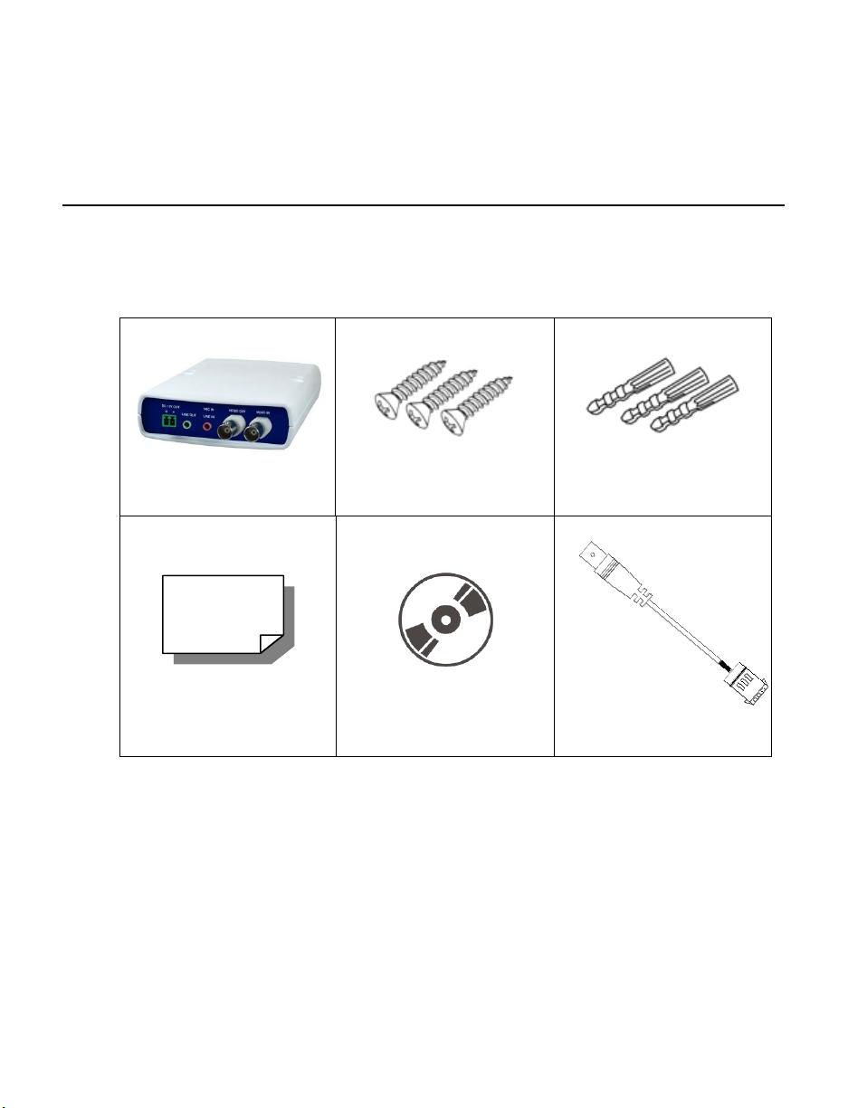
PACKAGE CONTENTS
Before proceeding, please check that the box contains the items listed here. If any item is
missing or has defects, DO NOT install or operate the product and contact your dealer for
assistance.
Video Server Screws Plastic Anchors
Quick Start Guide CD DC Jack Cable (300mm)
12
Page 13
SETUP AND CABLE CONNECTION
Before installing or connecting the video server, please refer to this section.
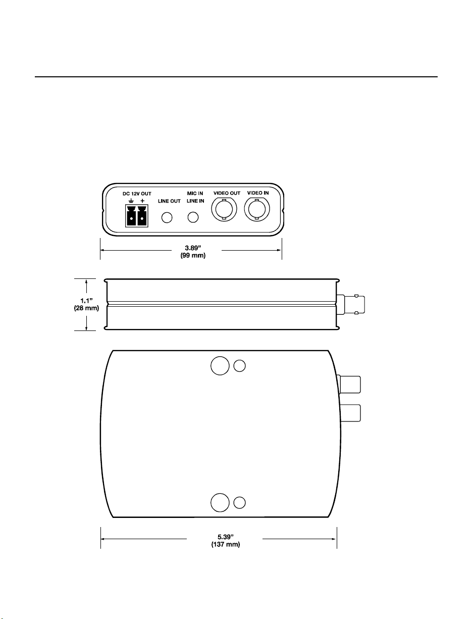
Video S erver Setup
Dimensions
30145AB 13
Page 14
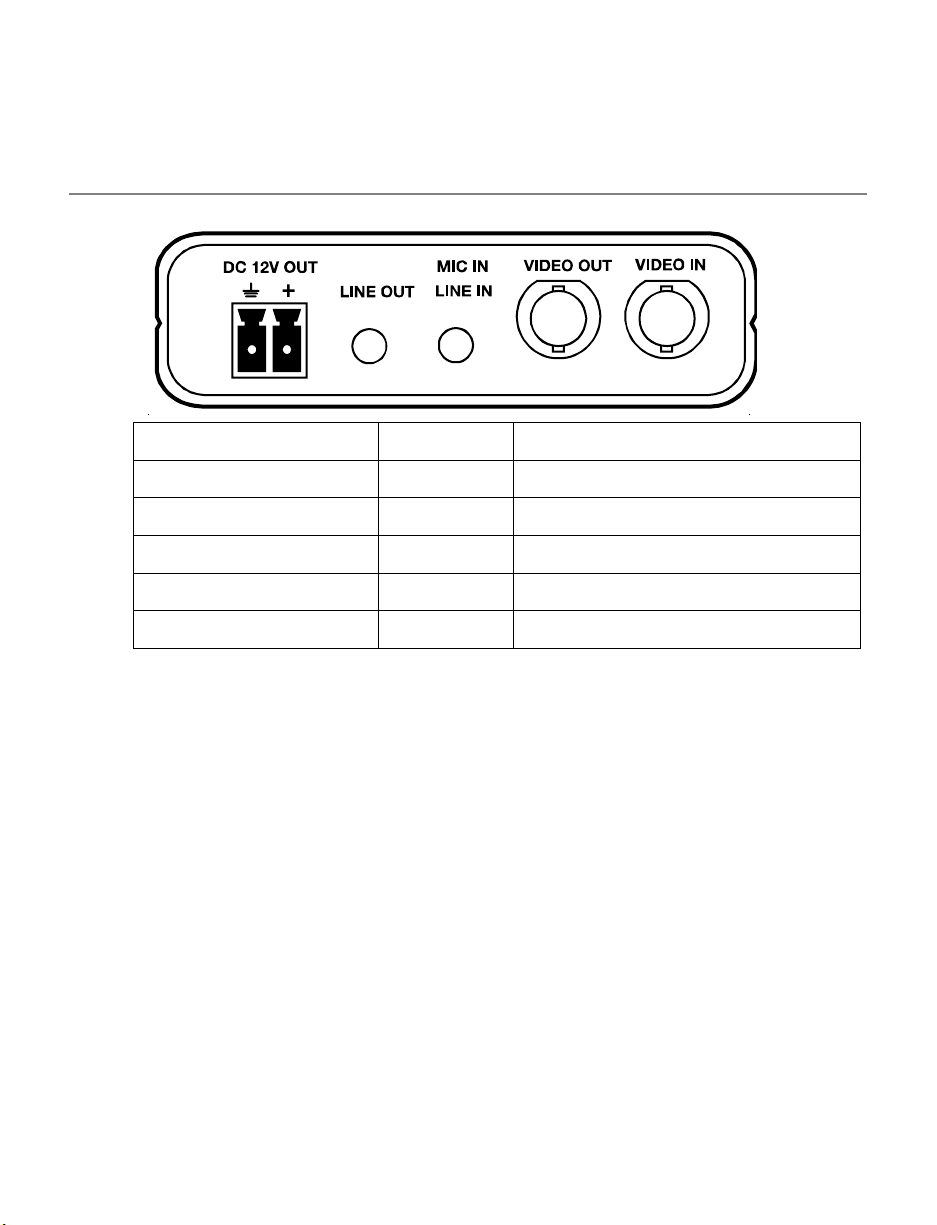
Connector Definition
Front
Connector Pin Definition
DC 12V OUT - Power Output Connection
LINE OUT - Audio Output
MIC IN / LINE IN - Audio and Microphone Input
VIDEO OUT - Analog Video Output to Monitor
VIDEO IN - Analog Video Input to Video Server
14
Page 15
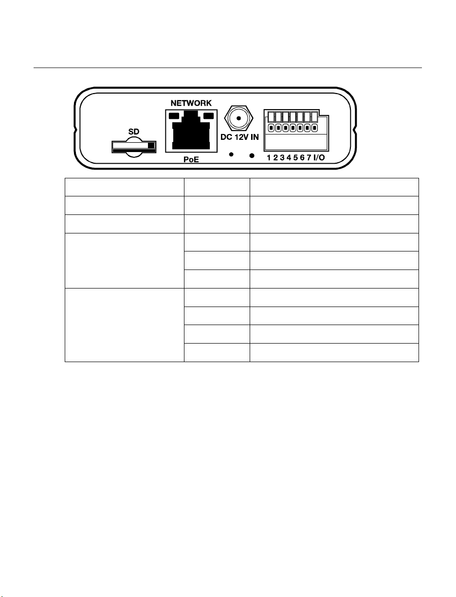
Rear
Connector Pin Definition
NETWORK / PoE - RJ-45 10/100 Mbps Ethernet / PoE
DC 12V IN - Power Input
RS-485 1 D+
2 D3 RS-485 GND
Alarm I/O 4 IN- (GND)
5 IN+
6 OUT7 OUT+
30145AB 15
Page 16

Video S erver Cable Definition and Requirements
The Network Video Server requires a network cable to carry the video signals to the
remote viewing site.
Network Cable
Network cable max length is 328 feet (100m). To avoid signal attenuation, OpenEye
recommends that you do not exceed 295 feet (90m). You can use Power over Ethernet
(PoE) to power compatible cameras using network cables up to the max length.
Power Connection
Make sure the power cable is correctly and firmly connected to the video server.
Power Wire Length Specifications
Wire
Gauge
22 27 feet 14 175 feet
20 44 feet 12 279 feet
18 69 feet 10 444 feet
16 110 feet
Note Ensure that the power supply corresponds with the power requirements of the
Maximum
Distance
video server or the device may be damaged. Contact a qualified maintenance
engineer with any problems.
Wire
Gauge
Ethernet Cable Connection
Connect one end of the CAT 5 Ethernet cable to the RJ-45 connector of the camera and
the other end of the cable to the network switch or router.
Note In some cases, you may need to use an Ethernet crossover cable when
connecting the video server directly to the recorder.
Check the status of the link indicator and activity indicator LEDs. If the LEDs are unlit,
check the LAN connection.
The Green link light indicates a good network connection.
Maximum
Distance
16
Page 17
The Orange activity light flashes to indicate network activity.
CAMERA FINDER
OPENEYE IP FINDER
Use the included IP Finder software to easily find your network device for initial setup. The
OpenEye IP Finder software is included on the CD with all OpenEye IP devices.
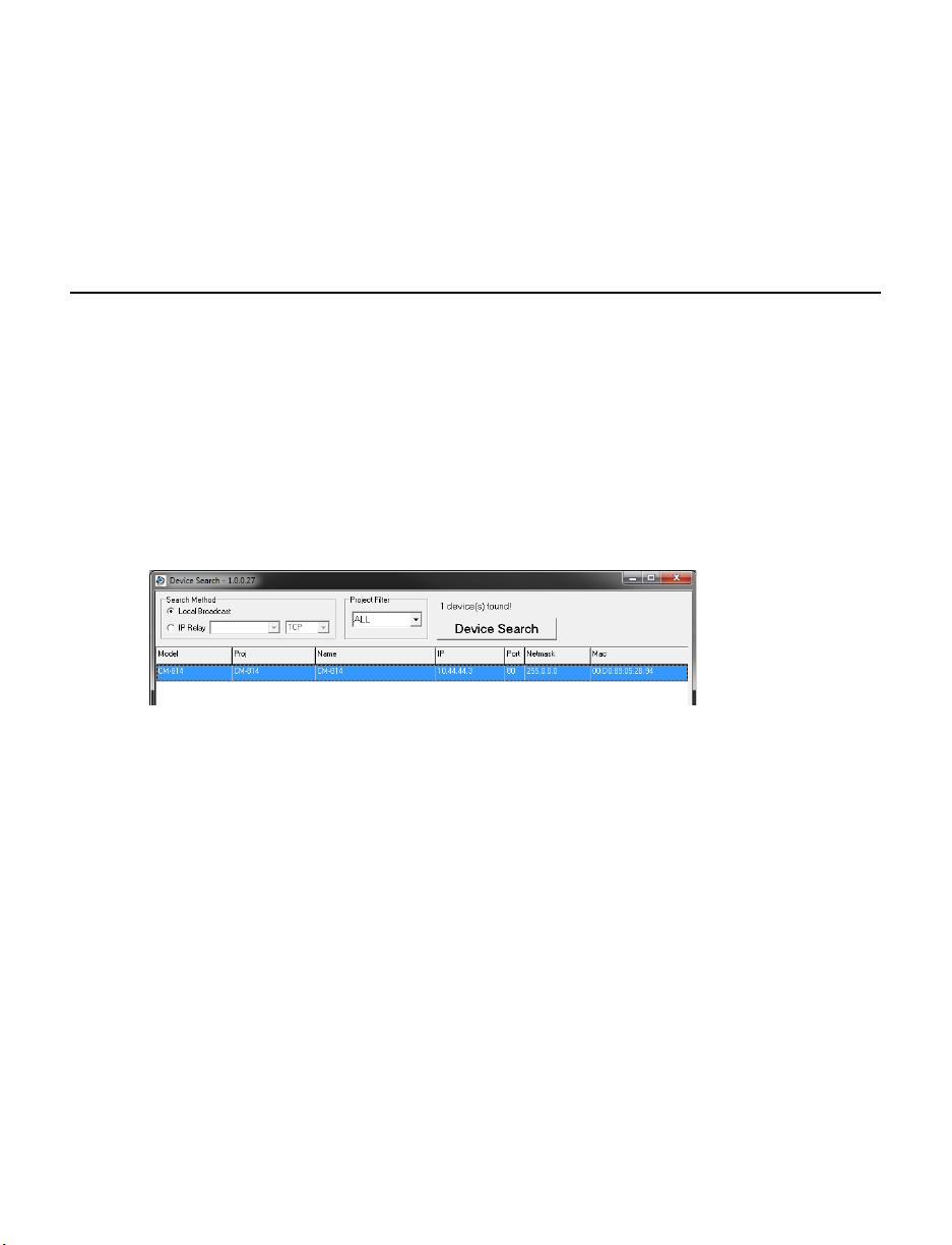
Finding IP Devices
1. Open the Software CD on the recorder.
2. Click Software on the software disc menu.
3. Click OpenEye IP Finder.
4. Click Device Search on the Device Search window.
5. If a Windows Security Alert window opens, click Unblock to allow the IP utility to
access your network.
6. Click Device Search again to find all connec ted I P devi ces .
Tip The default IP address of the VS201 is 192.168.0.250
7. Right-click the desired network device and select Browse.
8. Type the default username and password in the login window to access the video
server using your internet browser.
Default Username and Password
The username and password are case sensitive. It is strongl y recommen ded that the
password be changed after the initial setup to prevent unauthorized access.
Username – Admin
Password – 1234
30145AB 17
Page 18

Changing the Netw ork Type
You can change the network type from Static IP to DHCP easily from the list of connected
IP devices. To change the network type to DCHP:
1. On the list of connected IP devices locate the desired network device and record the
MAC address,
2. Right-click the network device row and select Network Setup.
3. Select the DCHP option on the Network Setup window and then click Apply.
4. Click OK to acknowledge the change.
5. After one minute, click Device Search to search for all conne cted IP devi ces .
6. Locate the network device using the MAC address recorded earlier and double click
the network device row.
7. Type the Username and Password to access the network device.
SETUP & CONFIGURATION
CONNECTING TO THE NETWORK DEVICE
1. Locate the network device on the IP Finder list.
2. Double-click the network device to open the Viewer software in your web browser.
3. Log in to the network device with the appropriate User Name and Password.
Note The default User name is Admin and the default Password is1234. The
username and password are case sensitive. OpenEye recommends you change
the Admin password for security reasons.
Administrator/User Privileges
The Administrator account has the authority to configure the network device and authorize
user access to the network device. The User accounts have access to the network device
with limited authority as defined by the Administrator.
18
Page 19

VIEWER SOFTWARE
You must install the viewer software on your PC or DVR to configure the device. The
viewer software will install automatically the first time you connect to the network device. If
your internet browser doesn’t install the viewer software, check the security settings or
ActiveX controls and plug-in settings. If your internet browser asks for permission to install
the ActiveX control, you must allow the ActiveX control to continue the installation.
Viewer Tabs
Home – Monitor live video.
System – Set the host name, system time, root password, and network related settings.
(Admin access only)
Streaming – Modify the video resolution and select the audio compression type.
PTZ –Control a PTZ camera and access the camera’s on screen menu (if applicable).
Logout – Change user.
30145AB 19
Page 20

Home
Screen Size Adjustment – Click the screen size buttons to adjust image display size x1/2
and full screen.
Digital Zoom Control – In full screen mode, right-click to activate digital zoom and use
the scroll wheel to zoom in/out.
Pan/Tilt Control – Move the cursor to the live video pane and drag the poi nter in
the desired direction.
Talk – Talk allows the local site to talk to the remote site. This function is only available to
Users who have been granted this privilege by the Administrator.
20
Page 21

Snapshot – Click the button, and a JPEG snapshot will automatically be saved in
the appointed place. The default location is: C:\.
Note If you are using Windows Vista or 7, you will need to change the Snapshot
location. Windows UAC does not allow internet programs to write directly to C:\
for security reasons.
Zoom – Click Wide or Tele to zoom out or in.
Focus
• Auto – Click Auto to enable Auto Focus mode. In Auto Focus mode, the camera will
automatically and continuously adjust focus regardless of zoom changes or view
changes of the camera.
• Manual – Click Manual to enable the Near and Far buttons for manual focus control.
30145AB 21
Page 22

System
Note The System tab is only accessible by the Administrator.
System
22
Host Name – The Host Name is used to identify the netw ork dev ice on your system. If
camera based Motion Detection is enabled and is set to send alarm message by
Mail/FTP, the host name entered here will display in the alarm message.
Time Zone – Select your time zone.
Sync With Computer Time – Select to synchronize the network device date and time
with the connected DVR.
Manual – Set video date and time manually.
Sync with NTP server – Network Time Protocol (NTP) is an alternate way to synchronize
your network device’s clock with a NTP server. Specify the server you wish to synchronize
in the NTP Server box. Then select an Update Interval. For more information about NTP,
visit www.ntp.org.
Page 23

30145AB 23
Page 24

Security
Admin Password
To change the administrator password, type a new password in the Admin Password box
and confirm below.
Note The maximum length of the password is 14 characters. The following characters
are valid: A-Z, a-z, 0-9 and !#$%&’-.@^_~.
24
Page 25

Add User
The user name and passwords are limited to 16 characte r s. There is a maximum of twenty
user accounts
1. Type the new User name and Password
2. Select the appropriate check boxes to give the user Camera Control, Talk and Listen
permissions.
I/O access - Basic functions that enable users to view video when accessing to the
network device.
Camera control - Allows the User to change camera para m eters on the Camera tab.
Talk/Listen --Talk and Listen functions allow the user at the local site (DVR) to
communicate with, the administrator at the remote site.
3. Click Add.
Delete user
1. Select the user name on the User Name list
2. Click Delete to remove the us er.
Edit user
1. Select the user name on the User Name list
2. Click Edit to edit the user password and permissions.
3. Type a new password or the existing password in the User password box
Note You must type a password in the User password box to make any changes to
an account.
Note For security reasons every time the user properties are opened, the access
boxes are automatically unchecked. Make sure you re-check any user access
options any time you edit the user properties..
30145AB 25
Page 26

Network
You can choose to use a fixed IP address or a dynamic IP address (assigned by a DHCP
server or router) for the network device.
Get IP address automatically (DHCP)
The video server comes preconfigured with a fixed IP address, selecting Get IP address
automatically requires a router or DHCP server to assign an IP address to the network
device.
Note Each network device has a unique Media Access Control (MAC) address, which
can be used to identify the network device on the network. Record the MAC
address of the network device, which can be found using the OpenEye IP Finder
application and on the label of the network device, for identification in the future.
26
Page 27

Use fixed IP address
To set up a new static IP address:
1. Select the Use fixed IP address option.
2. Type a new IP address in the IP address box.
3. Type a new address in the Default Gateway box.
4. Click Save to confirm the new setting.
When using static IP address to log in to the network device, you can access it either
through OpenEye IP Finder software or type the IP address directly in the Address bar of
your internet browser.
General
• IP address – The IP Address is necessary for network identification.
• Subnet mask - Used to determine if the destination is in the same subnet. The
default value is 255.255.255.0.
• Default gateway - Used to forward frames to destinations on different subnet s or for
internet access.
• Primary DNS - The primary domain name server that translates hostnames into IP
addresses.
• Secondary DNS - A secondary domain name server that backups the primary DNS.
Advanced
• Web Server port - Defines the port that Internet Explorer uses to connect over the
web and view video. If this port is changed then the new port must be defined when
attempting to web connect (ex: if your network device’s IP address is 192.168.0.100
and you change the web port to 8001, then you must type http://192.168.0.100:8001
in your browser).
• RTSP port – The default RTSP port is 554; setting range: 1024 ~65535.
• MJPEG over HTTP port - The default HTTP Port is 8008; setting range: 1024
~65535.
30145AB 27
Page 28

DDNS
Note The MJPEG over HTTP port must not be the same as the web server port.
DDNS (Dynamic Domain Name Service) is a service that allows a connection to an IP
address using a hostname (URL) address instead of a numeric IP address. Most Internet
Service Providers use Dynamic IP Addressing that frequently changes the public IP
address of your internet connection; this mea ns when connecting to the network device
over the internet you would need to know if your IP address has changed. DDNS
automatically redirects traffic to your current IP address when using the hostname
address.
28
• Enable DDNS – Select the check box to enable DDNS.
• Provider - Select a DDNS host from the Provider list.
• Host name - Type the registered domain name in the field.
• Username/E-mail - Type the username or e-mail required by the DDNS provider for
authentication.
• Password/Key - Type the password or key required by the DDNS provider for
authentication.
Page 29

30145AB 29
Page 30

The network device can send an e-mail via Simple Mail Transfer Protocol (SMTP) when
motion is detected or when the sensor input is activated. SMTP is a protocol for sending
e-mail messages between servers. SMTP is a relatively simple, text-based protocol,
where one or more recipients of a message are specified and the message text is
transferred. The configurati on page is show n as follows:
Two sets of SMTP accounts can be configured. Each set includes SMTP Server, Account
Name, Password and E-mail Address settings. For SMTP server, contact your network
service provider for more specific information.
30
Page 31

FTP
The network device can send alarm message to a specific File Transfer Protocol (FTP)
site when motion is detected or when the sensor input is activated. You can assign alarm
message to up to two FTP sites.
• Enter the FTP details, which include server, server port, user name, password and
remote folder, in the appropriate boxes and click Save when finished.
30145AB 31
Page 32

Application (Alarm Settings)
The video server is equipped with one alarm input and one alarm output to connect to an
alarm system to capture alarm images and notify an OpenEye recorder. Make sure the
alarm connections are properly wired before conf iguring alarm related settings on the
Application screen.
32
Alarm Switch
• Alarm Switch – Enable or dis able the alarm function.
• Alarm Type – Select an alarm type, Normally closed or Normally open, that
corresponds with the alarm application.
• Alarm Output – Define the alarm output signal as low (normally open) or high
(normally closed).
Triggered Action
Specify alarm actions that will take place when the alarm is triggered.
• Enable Alarm Output – Select this option to activ ate the alarm output.
Page 33

• Send Message by FTP/E-Mail – Select to send an alarm message to the configured
FTP and/or E-Mail when an alarm event occurs.
• Upload Image by FTP – Select to assign an FTP site. When the alarm i s triggered,
event images will be uploaded to the configured FTP site.
• Upload Image by E-Mail – Select to assign an e-mail address. When the alar m is
triggered, event images will be sent to the configured e-mail address.
Note Make sure SMTP or FTP configuration has been completed. See the Mail and
FTP section of this manual for further details.
File Name
Enter a file name in the box, ex. image.jpg. The uploaded image’s file name format can be
set in this section. Please select the one that meets your requirements.
• Add date/time suffix
File name: imageYYMMDD_HHNNSS_X X . jpg
Y: Year, M: Month, D: Day
H: Hour, N: Minute, S: Second
X: Sequence Number
• Add sequence number suffix (no maximum value)
File name: imageXXXXXXX .jpg
X: Sequence Number
• Add sequence number suffix (limited value)
File Name: imageXX.jpg
X: Sequence Number
The file name suffix will end at the value entered in this box. For example, if the
setting is up to “10,” the file name will start from 00, end at 10, and then start all over
again.
• Overwrite - The original image on the FTP site will be overwritten by the new
uploaded file with a static filename.
30145AB 33
Page 34

Motion Detection
Motion Detection allows the video server to detect motion and trigger alarms when motion
in the detected area exceeds the determined sensitivity threshold value.
In the Motion Detection page, there is a motion detection window (red box) displayed on
the Live View Pane. The Motion Detection window defines the motion detection area. To
change the size of the Motion Detection window, drag the edge of the frame to resize.
You can add up to 10 motion detection windows.
• Click add under the Live View Pane to add a Motion Detection window.
• To delete a Motion Detection window, use the mouse to select the frame and click
delete.
34
Page 35

When motion detection is activated, the Motion pop-up window will open.
When motion is detected, the signals will be displayed on the Motion window as shown
below.
Motion Detection
Turn motion detection on or off. The default sett ing is Off .
Motion Detection Setting
• Sampling pixel interval [1-10] – Default value is 10, which means system will take
one sampling pixel for every 10 pixels.
• Detection level [1-100] – Default detection level is 10. This item sets the detection
level for each sampling pixel; the smaller the value, the more sensitive it is.
• Sensitivity level [1-100] – The default sensitivity lev el is 80, w hich means if 20% or
more sampling pixels are detected as changing, the system will detect motion. The
bigger the value, the more sensitive it is. As the sensitivity value is increased, the red
horizontal line in the motion indication window will be lowered accordingly.
30145AB 35
Page 36

• Time interval (sec) [0-7200] – The default interval is 10. The value is the interval
between each detected motion event.
36
Page 37

Triggered Action
You can specify which actions the network device should take w hen motion is detected.
• Enable Alarm Output – Select this option to activate the alarm output.
• Send Message by FTP/E-Mail – Select to send an alarm message to the configured
FTP and/or E-Mail when an alarm event occurs.
• Upload Image by FTP – Select to assign an FTP site. When the alarm i s triggered,
event images will be uploaded to the configured FTP site.
• Upload Image by E-Mail - Select to assign an e-mail address. When the alarm is
triggered, event images will be sent to the configured e-mail address.
Note Make sure SMTP or FTP configuration has been complete d. See the Mail and
FTP section of this manual for further deta il s.
File Name
Enter a file name in the box, ex. image.jpg. The uploaded image’s file name format can be
set in this section. Please select the one that meets your requirements.
• Add date/time suffix
File name: imageYYMMDD_HHNNSS_XX.jpg
Y: Year, M: Month, D: Day
H: Hour, N: Minute, S: Second
X: Sequence Number
• Add sequence number suffix (no maximum value)
File name: imageXXXXXXX .jpg
X: Sequence Number
• Add sequence number suffix (limited value)
File Name: imageXX.jpg
X: Sequence Number
The file name suffix will end at the value entered in this box. For example, if the
setting is up to “10,” the file name will start from 00, end at 10, and then start all over
again.
• Overwrite - The original image on the FTP site will be overwritten by the new
uploaded file with a static filename.
30145AB 37
Page 38

Storage Management
The video server has an integr ated mi croSD ™ card slot that can be used to record video
or images. The card slot is compatible with a microSD™ card up to 4GB (not included).
38
Device Information – Displays the storage total size and free space information of the
included microSD™ card.
Device Setting – Allows you to format the microSD card.
Device Cleanup Setting – Use this feature to enable overwrite settings on the SD card.
The network device can remove files from the card after they reach a certain age, or when
the card is a certain percent full.
Recording List – Displays a list of files saved to the card. You can delete files from the
card, or save them to your local PC.
Page 39

Note If you are using Windows Vista or 7, you will need to change the Snapshot
Recording
The recording schedule allows you to set up scheduled recording to the microSD™ card.
location. Windows UAC does not allow internet programs to write directly to C:\
for security reasons.
Recording Schedule – The video server can be set up to record continuously until the
card is full (or overwrite old data, see the Storage Management section). The network
device can also be set up to record only during a scheduled time. Select the days that you
would like to record, then input the recording start time and the recording duration.
30145AB 39
Page 40

Camera Control
When connecting a PTZ camera to the RS-485 control, use the camera control page to
set up the camera information. Enable the PTZ Camera control, select a protocol and
baud rate. The video server is compatible with OpenEye OPTIX 1, OPTIX 3, Pelco P and
Pelco D control protocols.
40
Page 41

File Location
The video server supports a JPEG snapshot and AVI recording function. You can specify
a storage location for the saved files. The default sett ing is: C: \.
Note If you are using Windows Vista or 7, you must change the File Location.
Windows UAC does not allow internet programs to write directly to C:\ for
security reasons.
Note Make sure the selected file path contains valid characters such as letters and
numbers.
30145AB 41
Page 42

View Log File
Click View Log File to view the system log file. The content of the file provides useful
information about configuration and connections.
42
Page 43

View User Information
The Administrator can view each user’s login information and privileges on the View User
Information page
View User Login Information
All users for the video server are listed under User information. The example below
shows that the Admin password is 1234 and there is one user with the username User
and the password 4321.
View User Privilege
Select a user account from the list and click get user privacy to view the permissions for
the user account.
30145AB 43
Page 44

View Parameters
Click View Parameters to view the system parameter settings.
44
Page 45

Factory Default
Use the factory default page to reset the video serv er to factory default setting if
necessary.
Set Default
Click Set Default to reset the network device to the factory default settings The system
will restart in 30 seconds.
Note The IP address will be restored to default IP addre ss .
Reboot
Click Reboot to restart the network device without changing the current device settings.
30145AB 45
Page 46

Software Version
The Software Version page di splays the curr ent software version.
46
Page 47

Software Upgrade
Upgrading the Video Server Viewer Software
Note Make sure the new firmware file is available before starting a software upgrade.
Do not change the file name, or the system will not be able to update to the new
firmware.
1. Click Browse and find the upgrade file.
2. Select the file name from the list under Step 2.
3. Click Upgrade. The system will check to find the upgrade file, and then start to
upload the upgrade file. The upgrade status bar will display on the page. When it
reaches 100%, the upgrade process is finished.
When the upgrade process is complete the viewer will return to Home page.
4. Close the internet browser.
5. Go to the Windows Control Panel and double-click Add or Remove Programs.
Locate the Camera Viewer software on the Currently installed programs list, and
click Remove to uninstall the previous software version.
30145AB 47
Page 48

6. Open the internet browser again and log in to the network device. The system will
automatically download the new version of the Camera Viewer software.
48
Page 49

Maintenance
Export the current configuration of the video server or import a configuration.
Note Do not import the configuration from a different OpenEye OPTIX IP device.
30145AB 49
Page 50

Video and Audio Streaming S e ttings
On the Streaming tab, you can configure specific video resolution, video compression
mode, video protocol, and audio transmission mode.
Video Format
Select the desired video resolution for the video server on the Video Format page. The
DVR will record video based on the resolution selected here.
50
Video Resolution – The video server provides two sets of video dual streaming formats
like the following:
• H.264 D1 (30fps) + MJPEG D1 (30fps)
• H.264 D1 (30fps) + MJPEG CIF (30fps)
Note When using H.264 + MJPEG, the MJPEG stream is always handled by the
device as stream 1 and the H.264 stream is stream 2.
Page 51

Video Deinterlace – The video server supports de-interlacing. You can choose to activate
the de-interlacing function or disable the function by selecting a mode from the list as
shown below:
• Inter Field Deinterlacing (off) • Intra Field Deinterlacing
GOV Settings – Sets the Group of Video (GOV) or Group of Pictures (GOP) length for the
H.264 streams. Use this to increase bandw idth if neces sary .
Video Compression
Select an MJPEG/H.264 compr ess ion mode appropriate for the application. You can also
select to display compression information on the Home page.
MJPEG compression settings:
• high compression, low bitrate, low quality
• middle compression, default
• low compression, high bitrate, high quality
H.264 compression settings:
• Highest compression, lowest quality
30145AB 51
Page 52

• Middle compression, default
• Low compression, highest quality
Video OCX Protocol
On the Video OCX protocol page, you can select different protocols for streaming media
over the network.
Video OCX protocol setting options include:
• RTP over UDP
• RTP over RTSP(TCP)
Select a mode according to your data delivery requirements. If you are transmitting over
the internet using a router and port forwarding, you will need to use RTP over RTSP
(UDP). You will also need to forward the RTSP port to the network device (see the
network setup page to find the RTSP port).
Multicast Mode
52
• RTSP over HTTP
• MJPEG over HTTP
Page 53

1. Enter all required data, including multicast IP address, H.264 video port, MJPEG
video port, audio port and TTL into each box.
2. Click Save to confirm the setting.
Video Frame Skip
Use video frame skipping to save bandwidth if necessary.
MJPEG/H.264 Frame Skipping options include:
• No skipping, default
• Frame skipping at 5 frame internal
• Frame skipping at 10 frame internal
• Frame skipping at 15 frame internal
Note Higher frame skipping rate will decrease video smoothness.
30145AB 53
Page 54

Audio
The audio setting page is show as below. In the Audio page, the Administrator can select
one transmission mode and audio bit rate.
Transmission Mode
• Full-duplex (Talk and Listen simultaneously) – In Full-duplex mode, the local and
remote sites can communicate with each other simultaneously, i.e. both sites can
speak and be heard at the same time.
• Half-duplex (Talk or Listen, not at the same time) – In Half-duplex mode, the
local/remote site can only talk or listen to the other site at a time.
• Simplex (Talk only) – In Talk only Simplex mode, the local/remote site can only talk
to the other site
• Simplex (Listen only) - The local/remote site can only listen to the other site.
• Disable - Turn off the audio transmission function.
54
Page 55

PTZ Settings
Use the PTZ tab to program a PTZ camera using the on screen menu of the camera.
OSD Menu
Click Menu to open the OSD menu of the camera, then use the arrow and enter buttons to
navigate the camera menu.
Logout
Click the Logout tab to open the login window and log in with a different user name and
password.
30145AB 55
Page 56

Compression
Motion Detection
Audio Streaming
User Accounts
PTZ Control
Input Voltage
SPECIFICATIONS
VIDEO SERVER SPECIFICATIONS
Model
Video Input
Video Output
Dual Streaming
Resolution
Frame Rate
Audio Inputs
Audio Outputs
Audio Compression
Alarm Input
Alarm Output
Network
Web Connection
User Levels
Connections
PTZ Protocols
Operational Temp
Active/Passive Cooling
Power Consumption
Rated Amperage
Weight
Dimensions
Housing
Voltage Out
Power Out
Max Current
NE-VS201
1CH BNC
1CH BNC loop out
H.264 / MJPEG
H.264 + H.264 / H.264 + MJPEG
NTSC: 720 x 480 / PAL: 720 x 576
NTSC: 30IPS @ D1 / PAL: 25IPS @ D1
Yes
1
1
Full-duplex, Half-duplex, Simplex
G.711 / G.726
1
1
10/100 Ethernet
IE (ActiveX)
20
Administrator or User
TCP/UDP/IP, HTTP, FTP, SMTP, ARP, ICMP, DHCP, Telnet,
RTP/RTSP
RS-485
Pelco D, Pelco P, Optix III, Optix I
14°F ~ 122°F (-10°C ~ 50°C)
Passive Cooling
4.2W
< 350mA
12vDC / PoE
0.44 lbs (0.2kg)
L: 5.39" (137mm) x W: 3.9" (99mm) H: 1.1" (28mm)
White / Blue
12vDC
6W
500mA
56
Page 57

Recommended
Application
Fixed Dome Cameras.
Do not use to power more than one other device.
30145AB 57
Page 58

Page 59

www.openeye.net
1-888-542-1103
© 2012 OpenEye
All rights reserved. No part of this publication may be reproduced by any means without written
permission from OpenEye. The information in this publication is believed to be accurate in all
respects. However, OpenEye cannot assume responsibility for any consequences resulting from
the use thereof. The information contained herein is subject to change without notice. Revisions or
new editions to this publication may be issued to incorporate such changes.
30145AB
 Loading...