


KS-200A/B
˵Ã÷Êé
˵Ã÷Êé
OPERATOR`S MANUAL
AIS Class B Transponder KS-200A
R
KS-200A/B
AIS Receiver KS-200B


SAFETY INSTRUCTIONS
Safety Instructions for the Operator
Safety Instructions for the Installer
WARNING
Do not open the equipment.
Only qualified personnel should work
inside the equipment.
Do not disassemble or modify the
equipment.
Fire,electrical shock or serious injury
can result.
Immediately turn off the power at
the switchboard if the equipment is
emitting smoke or fire.
Continued use of the equipment can
cause fire or electrical shock.Contact
a ONWA agent for service.
Use the proper fuse.
Use of a wrong fuse can damage the
equipment or cause fire.
Be sure the power supply is
compatible with the equipment.
Incorrect power supply may cause the
equipment to overheat.
WARNING
Do not open the cover unless totally
familiar with electrical circuits and
service manual.
Improper handling can result in
electrical shock.
Turn off the power at the switchboard
before beginning the installation.
Fire or electrical shock can result if the
power is left on.
Be sure that the power supply is
compatible with the voltage rating
of the equipment.
Connection of an incorrect power
supply can cause fire or equipment
damage.
Use the proper fuse.
Use of a wrong fuse can damage the
equipment or cause fire.

Table of Contents
FOREWORD 1
SYSTEM CONFIGURATION 6
KS-200A BASIC OPERATION 8
KS-200B BASIC OPERATION 9
INSTALLATION 10
1. Scope of Delivery 10
2. Power Connection 10
3. Antenna Installation 10
4. Installation of GPS Antenna 11
5. Installation of VHF Antenna 12
6. Connect to other navigational equipment 13
7. Connection to PC 14
8. Data Serial Port 14
MAINTENANCE and TROUBLESHOOTING 15
1. Maintenance 15
2. Troubleshooting 15
CONNECTION DIAGRAM 16
DIMENSIONS 17

FOREWORD
How AIS Works
1. What is AIS
AIS stands for Automatic Identification System. AIS increases
navigational safety and collision avoidance by transmitting vessel
identification, helping to reduce the difficulty of identifying ships when
not in sight (e.g. at night, in radar blind arcs or shadows or at distance)
by broadcasting navigational intentions to other vessels by providing ID,
position, course, speed and other ship data with all other nearby ships and
land based stations.
According to IALA regulations, AIS is defined as follows:
AIS is a broadcast Transponder system, operating in the VHF maritime
mobile band. It is capable of sending ship information such as
identification, position course, speed and more, to other ships and to shore.
It can handle multiple reports at rapid update rates and uses Carrier Sense
Time Division Multiple Access (CSTDMA) technology to meet these high
broadcast rates and ensure reliable and robust ship to ship operation.
The IMO defines the performance standards as follows:
Ship to ship working, ship to shore working, including long range
application, automatic and continuous operation, provision of information
messaging via PC and utilization of maritime VHF channels.
2. What AIS classes do exist?
There are two classes of AIS units fitted to vessels, Class A and Class B.
In addition AIS base stations may be employed by the Coastguard, port
authorities and other authorized bodies. AIS units acting as Aids to
Navigation (A to N) can also be fitted to fixed and floating navigation
markers such as channel markers and buoys.
1

2.1 Class A
Class A units are a mandatory fit under the safety of life at sea (SOLAS)
convention to vessels above 300 gross tons or which carry more than 11
passengers in International waters. Many other commercial vessels and
some leisure craft also may be fitted Class A units.
The Class A operation consists of three different types of messages:
Dynamic information:
position of the ship (derived from GPS)
time, when the position was measured in UTC
course over ground (COG)
speed over ground (SOG)
heading (HOG)
ship status
rotational speed/turn rate
Static information:
MMSI number
call sign and name of the vessel
length and width of the vessel
IMO-number of the vessel, if existent
type of vehicle
position of the GPS sensor onboard
Journey-related information:
draught of the vessel
type of cargo
port of destination and estimated time of arrival (ETA)
route plan, optional compulsory way, depending on the vessels
movement.
2

The following table shows the mandatory repetition rate of class A
transmissions linked to the ship`s movement:
anchored vessels 3 minutes
vessels at 0 14 kn 10 seconds
vessels at 0 14 kn, fast maneuver 3.3 seconds
vessels at 14 23 kn 6 seconds
vessels at 14 23 kn, fast maneuver 2 seconds
vessels at > 23kn 2 seconds
vessels at > 23 kn, fast maneuver 2 seconds
Static information as well as information belonging to the journey is
dispersed every 6 minutes.
The reporting intervals correspond to both radio channels (161.975 MHz,
162.025 MHz) together.
2.2 Class B
C
lass B: EN62287, 2005:
class B operation is described in the standard EN62287, published in
2005. This document is obligatory for class B.
Class B units are designed for fitting in vessels which do not fall into
the mandatory Class A fit category.
The KS-200A is a Class B AIS unit
Reporting intervals are:
Dynamic ship data:
boats at < 2 kn: 3 minutes
boats at > 2 kn: 30 seconds
Static ship data (similar to class A): 6 minutes
These intervals are the standard operation modes. Competent authorities,
like base stations, can have influence on the reporting intervals (as they
do with class A as well). Interval timing can be reduced down to 5
seconds in exceptional cases. There is no automatism to change the
30sec/3min dynamic intervals by the ship itself.
3

Physical:
-Dimension : 207mm (length) x 155.8mm (Width) x 50mm (Height)
-Weight : 0.8kg
Power:
-Input: 10 ~ 35VDC
-Power consumption 0,35A nominal , 2A peak
Electrical Interface:
-RS232 38.4kbaud bi-directional
Environmental:
-IEC 60945 (Cat C)
-Operating Temperature: -25 to +55
KS-200A:
GPS Receiver (AIS Internal)
-IEC 61108-1 compliant
Connectors
-VHF Antenna connector PL259 female
-GPS Antenna connector BNC female
-RS232 data connector Female 9 Way D-type
VHF Transceiver
-Transmitter x 1
-Receiver x 2 (one time shared between AIS/DSC)
-Frequency: 156.025 to 162.025 MHz in 25KHz steps
-Output power 33dBm 1.5 dB
-Channel bandwidth: 25KHz
-Modulation modes 25KHz GMSK / AFSK
-Bit rate 9600 b/s GMSK & 1200 b/s FSK
-RX sensitivity <-107dBm at 20% packet error rate
4

KS200B:
Connectors
-VHF Antenna connector PL259 female
-RS232 data connector Female 9 Way D-type
VHF Receiver
-Receiver x 2 (one time shared between AIS/DSC)
-Frequency: 156.025 to 162.025 MHz in 25KHz steps
-Channel bandwidth: 25KHz
-RX sensitivity <-107dBm at 20% packet error rate
Compliant with the following standards:
-IEC62287-1 (IEC standard, Class B shipbourne equipment)
-IEC60945 Edn 4.0 (IEC standard, environmental requirements)
-ITU-RM.1371-1 (Universal AIS Technical Characteristics)
-IEC61162-1 Edn. 2.0 (IEC standard, digital interfaces part 1)
-IEC61108-1 (IEC standard, GPS receiver equipment)
5

KS-200A SYSTEM CONFIGURATION
VHF Antenna
GPS Antenna
DC 10V 35V
POWE
R
Class B
AI
S
Transp
onder
KS-2
R
00A
TX
RX
6

KS-200B SYSTEM CONFIGURATION
VHF Antenna
DC 10V 35V
POWE
R
R
AIS Rec
KS-200
eiver
B
RX
7

KS-200A BASIC OPERATION
Turning Power ON/OFF
Turning Power ON
Press [ON/OFF] to ON direction to turn on the power.
Turning Power OFF
Press [ON/FF] to OFF direction to turn off the power.
Notice : If the equipment remain long time no use, it is better to turn off
the Main Power Source switch.
Class B AIS Transponder
KS-200A
Power Indicator
1. Transmitter Indicator blinking during transmit own ship AIS information
2. Receiver Indicator blinking during receive other vessels AIS information
3. Power Indicator lights up when equipment turns on.
Transmitter Indicator
Receiver Indicator
8

KS-200B BASIC OPERATION
Turning Power ON/OFF
Turning Power ON
Press [ON/OFF] to ON direction to turn on the power.
Turning Power OFF
Press [ON/FF] to OFF direction to turn off the power.
Notice : If the equipment remain long time no use, it is better to turn off
the Main Power Source switch.
Power Indicator
1. Receiver Indicator blinking during receive other vessels AIS information
2. Power Indicator lights up when equipment turns on.
9
Receiver Indicator

1.Scope of Delivery
INSTALLATION
Description
Main unit
Power Cable
Data Cable
Data Cable
CD
Operator's Manual
GPS Antenna
Part Number Quantity Remark
KS-200A/B
KS2-PWR
KS2-data1
KS2-data2
KS2-CD
KS2-manual
KA-07
One
One
One
One
One
One
One
Only for KS-200A
Only for KS-200A
2.Power Connection
Connect power cable to 12VDC (10~ 35VDC) supply, white wire to supply
positive +ve and black wire to supply negative -ve.
3. Antenna Connection
Connect the supplied GPS antenna to the BNC female connector on the
Main unit.
Connect VHF antenna (not supplied) to the PL-259 female connector on the
Main unit (Please refer to the connection diagram of Page 16 )
10

4. Installation of GPS Antenna
The GPS antenna is mounted in an elevated position and free of shadow
effect from the ship's superstructure.
The GPS antenna has a free view through 360 degrees with a vertical
angle of 5 to 90 degrees above the horizon.
As the received GPS signal is very sensitive to noise and interference
generated by other onboard transmitters, ensure that the GNSS antenna
is placed as far away as possible from radar, Inmarsat and Iridium
transmitters and ensure the GPS antenna is free from direct view of the
radar and the Inmarsat beam.
It is also important that the MF/HF and other VHF transmitter antennas
are kept as far away as possible from the GNSS antenna. It is good
practice never to install a GNSS antenna within a radius of 2 meters from
these antennas.
INSTALLTION WITH CLAMPS
Antenna
Mast(Pole)
Clamps
Antenna Cable
Connector
11

INSTALLTION WITH A PLPE (CUSTOMER`S CARE)
Antenna
Antenna Cable
Pipe
Connector
5. Installation of VHF Antenna
For the VHF antenna there is a VHF female bulkhead connector used, that
mounts to the back of the case.
The VHF antenna employed for AIS use:
Must be a dedicated antenna, i.e. not shared with any other VHF
transmitter/receiver.
Must be suitable for marine shipboard applications (index of protection,
ruggedness, means of mounting, etc.).
Should be omni-directional and vertically polarized with unity gain (0dB)
with a bandwidth sufficient to maintain VSWR <1.5 over the frequency
range 156-163 MHz. As a minimum the 3dB bandwidth must cover the
two AIS channels and the DSC Channel.
Should be mounted with at least a two meter vertical separation distance
from any other VHF antenna used for speech or DCS communication.
12

6. Connect to other navigational equipment
You can use the delivered cable (KS2-data1) to connect the AIS to other
navigational equipments such as plotter, radar etc.
Please connect the DB9 connector of KS2-data1 cable to the DB9 socket
of KS200A/B. Connect the other end of KS2-data1 cable to external
navigational equipments according to the following diagram :
DB9 pin no.
9876
DB9 (Male)
Wire color
1
2
3
4
5
6
7
8
9
NC
Orange RS232-TX
Green RS232-RX
NC
Black
NC
NC
NC
NC
Signal
Signal Return
1.5M
54321
PIN2 AIS OUT (Orange
PIN3 AIS IN (Green
PIN5 GND (Black
13

7. Connect to PC
You could use delivered cable (KS2-data2) to connect AIS data to PC as
following diagram:
KS-200A/B
2-Orange- TX Data
3-Green- RX Data
5-Black- GND
9-pin serial port of the computer
2- Receive data
3-Send data
5-GND
1.5M
DB9 (Male)
DB9 (Female)
8. DATA SERIAL PORT
The default baud rate of the data link is 38.4kBaud with 8 data bits, one
stop bit and no parity. The data interface conforms to IEC 61162-1.
The sent messages are VDM, VDO, RMC,and GSA are conform to
NMEA 0183. Please refer to NMEA 0183 for full details of these AIS
messages.
14

MAINTENANCE and TROUBLESHOOTING
1.Maintenance
Unauthorized opening of the KS200A/B system will invalidate the warranty.
Avoid using chemical solvents to clean the KS200A/B as some solvents can
damage the case material. To clean, wipe down with a damp cloth. The
KS200A/B contains no user serviceable parts. Contact your Service Agent
for repair or for replacing.
2.Troubleshooting
Problem Cause
Power cable broken
Cannot switch on
Unable to see AIS
vessel around
Other AIS vessel
unable to see us
(For KS200A)
Power supply problem
Fuse blown
KS200A/B not switch on Switch on KS200A/B
VHF antenna not connect
properly
No AIS vessel around Check again in harbor
KS200A not switch on Switch on KS200A
GPS antenna not connect
properly
VHF antenna not connect
properly
Incorrect power supply
voltage
Solution
Replace or reconnect power
cable
Check power supply
Replace suitable rating fuse.
Call service if fuse blown
again after replacement
Reconnect VHF antenna
Reconnect GPS antenna
Reconnect VHF antenna
Check power supply and
replace if necessary
15
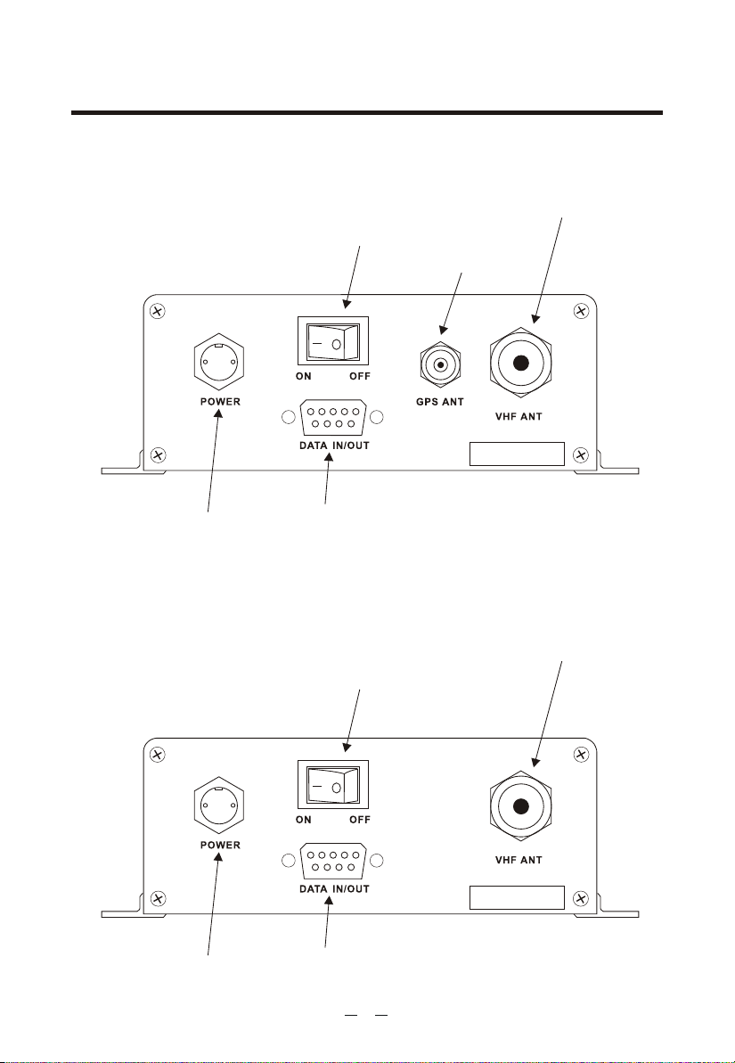
CONNECTION DIAGRAM
KS200A Connection Diagram
Power Switch
VHF antenna
GPS Antenna
S/NO.200A1001
Power Cable
Data cable
KS200B Connection Diagram
Power Switch
Power Cable
Data cable
16
VHF antenna
S/NO.200A1001

DIMENSION
155.8
126.6
50
14.6
17
5
4.4
17
207
17
155.8

 Loading...