Onwa KAP-866 User Manual

R
KAP-866
KAP-866
OPERATOR`S MANUAL
Autopilot
CONTENTS
WARNING 


 1
1
FEATURES 


 2
2
1 OPER ATION 


 3
3
1.1Control s 


 3
3
1.2Turning the power on/off 


 3
3
1.3Display backlight and contrast adjustment 


 4
4
1.4Standby Mode 


 4
4
1.5Auto Mode 


 5
5
1.5.1Weather Control 


 5
5
1.5.2Rudder Control (Rudder Ratio) 


 5
5
1.5.3Counter-Rudder Control 


 6
6
1.6Follow-Up Mode 


 6
6
1.7Navigation Mode 


 7
7
2 MENU SETTINGS 


 10
10
2.1Function Menu 


 10
10
2.1.1Set Rudder Limit 


 10
10
2.1.2Set Trim 


 11
11
2.1.3Stopwatch Timer Alarm 


 11
11
2.1.4Off Course Alarm 


 11
11
2.2Installation Menu 


 13
13
2.2.1Select Remote Unit 


 13
13
2.2.2Select Rudder Feedback unit 


 13
13
2.2.3Select Magnetic Sensor Unit 


 14
14
2.2.4Trim Setting 


 14
14
2.2.5Auto Heading Adjust 


 15
15
2.2.6Manual Heading Setting 


 16
16
2.2.7Heading Alignment Setting 


 17
17
2.2.8Language Setting 


 17
17
2.2.9Output Setting 


 18
18
2.2.10Factory Default Setting 


 18
18
2.2.11 Select Type of Steerin g System 


 19
19
CONTENTS
3 AUTOPILOT INSTALLATION 


 20
20
3.1Installation of Main Unit 


 20
20
3.1.1Position 


 20
20
3.1.2Wiring 


 20
20
3.1.3Magnetic Effect 


 20
20
3.1.4Power supply consideration 


 20
20
3.2Installation of Rudder Feedback 


 21
21
3.2.1Position 


 21
21
3.2.2Wiring 


 22
22
3.3Installation of Compass 


 23
23
3.3.1Installing a Compass-Top Sensor (KCS-20) 


 23
23
3.3.2Installing an indoor magnetic sensor unit (KFG-25) 

 24
24
3.3.3Installation an outdoor magnetic sensor unit (KFG-28) 
 26
26
3.4Installation of solenoil 


 27
27
3.5Installation of reversing motor pump 


 28
28
3.6NMEA Connection 


 28
28
3.7External Alarm Installation 


 29
29
3.8Installation of Remote Units 


 30
30
3.9Installation of external rudder indicator 


 31
31
4Commissioning Checks Connection Tests 


 32
32
5MAINTENANCE, TROUBLESHOOTING 


 33
33
5.1Preventive maintenance 


 33
33
5.2Troubleshooting 


 34
34
6 TECHNICAL PARAMETERS 


 35
35
6.1General 


 35
35
6.2Output /Input (IEC61162) 


 35
35
6.3Environmental Conditions 


 35
35
6.4Display 


 35
35
6.5Electrical parameters: 


 35
35
7INTERCONNECTION DIAGRAM 


 36
36
8DISPLAY UNIT SIZE 


 38
38
SAFETY INSTRUCTIONS
Safety Instructions for the Operator
WARNING
Do not open the equipment.
Only qualified personnel should work
inside the equipment.
Do not disassemble or modify the
equipment.
Fire,electrical shock or serious injury
can result.
Immediately turn off the power at
the switchboard if the equipment is
emitting smoke or fire.
Continued use of the equipment can
cause fire or electrical shock.Contact
a ONWA agent for service.
Use the proper fuse.
Use of a wrong fuse can damage the
equipment or cause fire.
Be sure the power supply is compatible with the equipment.
Incorrect power supply may cause the
equipment to overheat.
The useable temperature range
-15 to 55
to 55 for the display unit.
Use of the equipment out of those
ranges may damage the equipment.
Safety Instructions for the Installer
WARNING
Do not open the cover unless totally familiar with electrical circuits and service manual.
Improper handling can result in
electrical shock.
Turn off the power at the switchboard before beginning the installation.
Fire or electrical shock can result if the
power is left on.
Be sure that the power supply is compatible with the voltage rating of the equipment.
Connection of an incorrect power
supply can cause fire or equipment
damage.
Use the proper fuse.
Use of a wrong fuse can damage the
equipment or cause fire.
NOTICE
Observe the following compass safe distances to prevent interference to a magnetic compass:
|
Standard |
Steering |
|
Compass |
Compass |
Display unit |
0.4 m |
0.3 m |
|
||
|
|
|
Processor |
1.2 m |
1.2 m |
|
||
|
|
|

WARNING!
Automatic pilots are designed to be a navigational aid. As an automatic steering aid, an autopilot can alleviate the boredom of hand steering.
This allows the operator of the vessel time to attend to other duties, keep a more accurate check of navigation duties or just relax and enjoy the trip.
HOWEVER, THE AUTOPILOT SHOULD NOT BE LEFT SOLELY IN CHARGE OF THE VESSEL AND AN ADEQUATE WATCH SHOULD BE MAINTAINED AT ALL TIMES.
IT IS NOT RECOMMENDED THAT THE AUTOPILOT BE USED WHILE NAVIGATING IN RESTRICTED WATERWAYS AS WATER CURRENTS, WIND CHANGES OR RADIO TRANSMITTER INTERFERENCE MAY AFFCT VESSEL COURSE SUFFICIENTLY TO ENDANGER YOUR OWN OR OTHER VESSELS.
1

FOREWORD
Thanks you for purchasing the ONWA KAP-866 Autopilot.
The KAP-866 Autopilot controls the vessel steering through mechanical drive, reversing pump set, solenoid valves or relays.
The compass must be installed in a place free of magnetic interference, and connected to the autopilot via the cable supplied.
The rudder feedback must be attached to the rudder in such a way that it can accurately measure the position of the ship's rudder. This must also be connected to the autopilot via the cable supplied.
KAP-866 is designed and constructed to meet the rigorous demands of the marine environment. However, no machine can perform its intended function unless properly installed and maintained.
Please carefully read and follow the operation, installation and maintenance procedures set forth in this manual.
We would appreciate feedback from you.
Thank you for considering and purchasing ONWA.
2
1. OPERATION
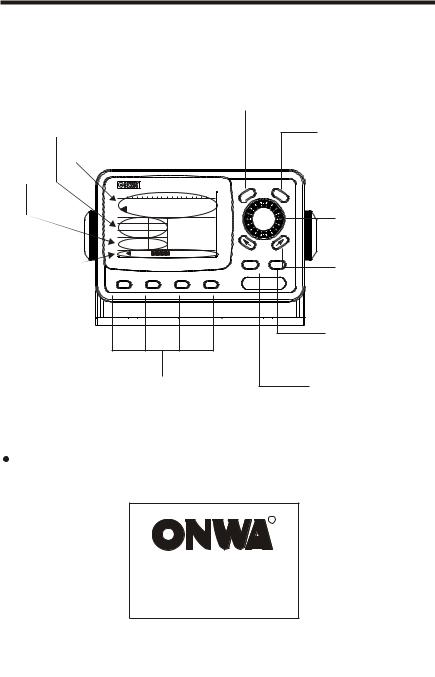
1.1 Controls
|
MENU: |
Ship's heading field |
Press once: Open Activate menu |
Press 5 sec: Activate installation menu |
Control field |
|
|
|
|
|
|
|
CTRL: |
|
|
|
|
|
|
|
|
Select controls setting. |
Mode field |
|
|
|
|
|
|
|
|
40 50 |
60 |
70 |
80 |
E 100 110 |
120 |
NU |
CTR |
KNOB/ENT: |
Heading |
080 |
|
ME |
L |
||||
|
|
|||||||
|
|
|
||||||
|
|
|
|
|
Choose menu item. |
|||
Weather |
|
16 |
|
Set Course |
|
|
|
Change course heading. |
Rudder |
|
10 |
|
060 |
|
|
||
|
|
|
|
Press the [Enter] |
||||
Mode |
|
A |
|
|
|
|||
Counter |
|
4 |
|
|
|
|
|
|
20 |
|
|
|
|
|
|
|
|
Rudder angle |
|
|
|
|
|
ESC |
POWER |
ARROW KEYS: |
field |
|
|
|
|
|
|
|
|
|
|
|
|
|
KAP-866 |
Press once to change one |
||
ST-BY |
AUTO |
|
F-UP |
NAV |
degree course-to-steer |
|||
|
|
|
|
|
|
|
|
|
|
|
|
|
|
|
|
|
POWER: |
|
|
|
|
|
|
|
|
To switch on/off the unit. |
|
|
|
|
|
|
|
|
To adjust display backlight |
|
|
|
|
|
|
|
|
and contrast |
Mode Selection
ESC:
Exit menu and operation.
1.2 Turning the power on/off
Power on
Press [POWER] once to switch on the unit with a "beep" sound.
R
KAP-866 Autopilot
Ver : 20120101001
3

TURNING OFF
IN 3 S EC
NOTE: If the device is a long time when not in use,Better to turn off the
main switch of the power supply unit.
1.3 Display backlight and contrast adjustment
1.Press the [POWER] key. Dialog box for adjustment of Panel brilliance and display contrast.
40 50 60 70 80 E 100 110 120
Heading
|
|
|
|
|
|
|
|
|
|
|
|
|
|
|
8 |
|
|
|
|
|
|
Weath |
|
|
|
|
|
|
|
|
|
|
0 |
|
|
|
|
|
|
|
|
|
|
|
|
|
|
|
|
|
|
||
|
|
|
|
Rudd |
|
|
|
|
|
|
|
|
|
|
42 |
|
|
|
|
|
|
Coun |
|
|
|
|
|
|
|
|
|
|
|
||
|
|
|
|
|
|
|
|
|
|
|
|
|
|
|
|
|
|
|
|
|
|
Mode |
A |
|
|
|
|
|
|
|
|
||||
|
|
|
20 |
|
|
|
|
|
|
|
|
|
|
|
|
|
|
2. Turn the Knob |
to |
select BRILL box |
and |
press the Knob to confirm, then |
|||||||||||||
turning the Knob to change the backlight |
brilliance and press the Knob |
||||||||||||||||
again to confirm the setting. |
|
|
|
|
|
|
|
|
|
|
|||||||
3. Turn the Knob |
to |
select CONTRAST |
|
|
box |
and press the Knob to confirm, |
|||||||||||
then turning the Knob to change the |
display contrast and press the Knob |
|||||||||||||||||||||
again to confirm the setting. |
|
|
|
|
|
|
|
|
|
|
|
|
|
|
|
|
|
|
|
|
|
|
4. Press [ESC] to exit. |
|
|
|
|
|
|
|
|
|
|
|
|
|
|
|
|
|
|
|
|
|
|
|
|
|
|
|
|
|
|
|
|
|
|
|
|
|
|
|
|
|
|
|
|
|
1.4 Standby Mode |
|
40 50 60 |
70 80 |
E 100 110 120 |
|
|||||||||||||||||
|
|
|
|
|
|
|
|
|
|
|
|
|
|
|
|
|
|
|
|
|
|
|
|
|
|
Heading |
080 |
|
|
|
|
|
|
|
|||||||||||
When switching on the unit it stays on |
|
|
|
|
|
|
|
|
|
|
|
|
|
|
|
|||||||
Standby Mode and "Man" display on the |
|
|
|
|
|
|
||||||||||||||||
|
Weather |
3 |
|
Heading |
|
|||||||||||||||||
|
|
|
|
|
080 |
|
||||||||||||||||
Mode field to indicate the steering oper- |
|
Rudder |
10 |
|
|
|||||||||||||||||
|
Counter |
4 |
|
|
||||||||||||||||||
ate manually. |
|
|
|
|||||||||||||||||||
|
Mode |
Man |
|
|
||||||||||||||||||
In any steering mode, press [ST-BY] can |
|
|
|
|
|
|
|
|
|
|
|
|
|
|
|
|
|
|
|
|
|
|
|
3 |
|
|
|
|
|
|
|
|
|
|
|
|
|
|
|
|
|
|
|
|
|
return to manual steering mode. |
|
|
|
|
|
|
|
|
|
|
|
|
|
|
|
|
|
|
|
|
|
|
|
|
|
|
|
|
|
|
|
|
|
|
Command field |
||||||||||
Mode field |
|
|
|
|
||||||||||||||||||
Rudder Angle Field
4

1.5 Auto Mode
Press [Auto] change steering mode to Auto and "A" display on the Mode field to indicate the steering operate automatic to the set course.
The autopilot will lock on to the current heading. Change course as follows :
40 50 60 |
70 |
80 E 100 110 120 |
|||||||||||||||||||
|
|
|
|
|
|
|
|
|
|
|
|
|
|
|
|
|
|
|
|
|
|
|
|
Heading |
080 |
|
|
|
|
|
|
||||||||||||
|
|
|
|
|
|
|
|
|
|
|
|
|
|
||||||||
Weather |
|
16 |
|
|
Set Course |
||||||||||||||||
|
|
|
|
060 |
|||||||||||||||||
Rudder |
|
10 |
|
||||||||||||||||||
Counter |
|
4 |
|
||||||||||||||||||
Mode |
|
A |
|
||||||||||||||||||
|
|
|
|
|
|
|
|
|
|
|
|
||||||||||
|
|
|
|
|
|
|
|
|
|
|
|
|
|
|
|
|
|
|
|
|
|
20
a)Rotating the Knob to change the course-to-steer by one degree for each "click".
b)Pressing the [  ] or [
  ] arrow keys will also cause a one degree course change for each press to corresponding direction.
Controls:
press the [CTRL] to select corresponding controls, Weather, Rudder and Counter Rudder. Turning the Knob to change the setting of the controls then press the Knob to confirm the setting or press [ESC] to exit.
1.5.1 Weather Control
This setting is used for adjusting the autopilot's reponse on varies sea conditions. The weather value sets the desired accuracy of the vesse l steering. A high weather setting will cause the vessel to steer very accurately but may cause excessive use of the steering.
In good weather, set this control to a high value, but ensure that the drive arrows display on ship's heading field would not flickering continuously. This will give the straightest possible course.
In poor weather, reduce this setting to prevent over-working the steering.
1.5.2 Rudder Control (Rudder Ratio)
This setting |
is used to determine the amount of rudder that the vessel requires |
|
for |
steering |
(actually, the amount of rudder angle applied for a given angle |
off |
course). |
|
The centre position is usually suitable for most vessels, but also should depends on the vessel's steering be sensitive or slow, adjustment maybe required.
In general, an agile vessel with a relatively large rudder or very small keel will require a small rudder setting. A large, slow vessel may require a high value for the rudder ratio.
5

This may also be adjusted according to speed, low speeds may require more rudder angle for steering than high speeds.
A value of 1 signifies the minimum amount of applied rudder (for sensitive steering, large rudders or low gearing ratio.
A value of 20 signifies the minimum amount of applied rudder (for vessels with slow steering, small rudders or high gear ratio).
When the rudder setting is too low, turns will take an excessive amount of time and the vessel may wander .
When the rudder setting is too high, turns will be rapid and the vessel will oversteer.
1.5.3 Counter-Rudder Control
In some vessels, changing course requires a large amount of rudder to be applied Initially, and then a smaller amount of rudder in the REVERSE direction to stop the vessel from swinging beyond its desired course. This is called counter-rudder.
The KAP-866 Autopilot has this feature built-in. A counter-rudder setting of "1" gives no counter-rudder steering, suitable for light and manouverable vessels. If you find your ship over-steering when under autopilot control, increase the counter-rudder setting by a couple of steps, and see if the next course change behaves better.
Once the correct setting is found for your vessel, it should not need to be changed. Unless the loading of your vessel is changed.
If you adjust the counter-rudder seting to "A" the counter-rudder functioning automatically apply depends on the rate of vessel turning to the set course.
1.6 Follow-Up Mode
Press [FU] to change the the Mode field to indicate on the Command field.
steering mode to Follow Up and "FU" display on the rudder steer follows the set command angle
6
Set rudder |
angle can |
change the course of the |
40 50 60 |
70 80 |
E 100 110 120 |
||||||||||||||||||
|
|
|
|
|
|
|
|
|
|
|
|
|
|
|
|
|
|
|
|
|
|
|
|
autopilot : |
|
|
|
|
Heading |
080 |
|
|
|
|
|||||||||||||
|
|
|
|
|
|
|
|
|
|
|
|
|
|||||||||||
a) Rotating |
the knob |
will change the rudder |
|
|
|
|
|
|
|
|
|
|
|
||||||||||
angle command by one degree for each "click". |
Weather |
16 |
|
|
|
|
P20 |
||||||||||||||||
Rudder |
10 |
|
|
|
|
||||||||||||||||||
|
|
|
Counter |
4 |
|
|
|
|
|||||||||||||||
Rudder will steer and stop on the set angle and |
Mode |
FU |
|
|
|
Set Rudder |
|||||||||||||||||
direction. |
|
|
20 |
|
|
|
|
|
|
|
|
|
|
|
|
|
|
|
|
|
|
|
|
|
|
|
|
|
|
|
|
|
|
|
|
|
|
|
|
|
|
|
|
|
|
|
|
Rotate the Knob to clockwise direction to drive the rudder to Starboard side while rotate the Knob to Counter-Clockwise direction to drive the rudder to Port side.
b) Pressing the [ |
] or [ |
] arrow keys will cause a one rudder angle change |
in that direction. |
|
|
1.7 Navigation Mode
For use when KAP-866 is interfaced to a GPS
Navigator with NMEA0183 data output. |
40 50 60 |
70 |
80 E 100 110 120 |
||||
In Navigation mode this allows the autopilot to |
|
Heading |
080 |
|
|||
be directed by the GPS Navigator, enabling |
|
|
|
|
|||
automatic heading changes and eliminating the |
Weather |
|
16 |
|
BRG |
||
effects of wind and tide. |
Rudder |
|
10 |
|
060 |
||
Counter |
|
4 |
|
||||
The number displays on the Command field |
Mode |
|
Nav |
|
|||
indicates the course-to-steer,which will be the |
|
|
|
|
|
|
|
20 |
|
|
|
|
|
|
|
bearing between the origin ad destination Waypoints,plus a factor to correct for the Current crosstrack-error(XTE).
Engaging Navigation Mode
Press [ NAV] change the steering mode to Navigation mode and "NAV" display on the Mode field to indicate the steering is directed by the connected GPS Navigator.
The vessel |
will begin turnin from its current course to the course requested by |
|
the GPS Navigation. |
||
If |
no GPS |
data is being received by the KAP-866, the autopilot will lock onto |
the |
course |
of the vessel at the time that Navigation Mode was engaged, and the |
No GPS Data alarm shall sound.
7

Setting up your GPS Navigator
Because there are a great variety of GPS Navigator that will work with this autopilot, the following is a guide only. For more information, Please study your GPS Navigator manual.
The GPS Navigator must be set up to output NMEA0183 data on a pair of wires which are connected to the "GPS IN" terminal connections on KAP-866.
The data generated must include at least one of the followings:  The APA sentence.
The APB sentence.
The BOD and XTE Sentences.
If only the XTE data sentence is available, the pilot can steer in a Restricted manner. See later in this section.
The GPS unit must then be commanded to go to a waypoint, or to follow a line joining two or more waypoints (called a route).
This unit will then send information to the autopilot from which can be calculated the course-to-steer. IF several waypoints are linked together into a single route, and the GPS unit is set to "auto-sequenence" between them, and an "arrival zone" of more than 0.1 NM(Nautical Miles)is set so that the GPS can detect when the vessel has reached a waypoint, then the KAP-866 will be able to steer from each waypoint to the next without intervention.
If only the XTE information is available from your GPS unit then your vessel must be on track, and heading in the correct direction before engaging the GPS mode, and the auto-sequencing feature is not available.
8

Remember:
Prior to engaging Navigator mode, a route must be programmed into the GPS
for the Autopilot to follow.
No GPS Data Alarm
If the autopilot is not receiving valid information while in GPS Mode, the No GPS Data alarm will sound, and "NO GPS" will blink on the display. This counld be caused by:
Incorrect wiring of the GPS to the KAP-866.
Incorrect data output from the GPS unit.
No route set up or selected in the GPS unit.
No location fix at the GPS unit.
The bearings generated by the GPS unit must correspond to the bearings the KAP-866 is receiving from its magnetic compass. The greater the difference between these Bearings, the less accurate will be the Navigator mode steering.  Ensure that the GPS unit has the correct magnetic correction factor.
Ensure that the KAP-866 compass is correctly aligned and installed.
9
 Loading...