


R
KV-300
KV-300
OPERATOR`S MANUAL
VHF DSC MARINE TRANSCEIVER

CONTENTS
1. ABOVE ALL... SAFETY!


 1
1
1.1Symbols used


 1
1
1.2Warnings


 1
1
1.2.1General


 1
1
1.2.2Radio Frequency/Installation


 1
1
1.2.3Automatic Transmitter Identification System (ATIS)


 2
2
1.2.4Environmental


 2
2
1.3ETSI Information


 2
2
1.4Assistance


 2
2
1.5Manual Notes


 2
2
2.INTRODUCTION


 3
3
2.1Generalities


 3
3
3.DESCRIPTION OF CONTROLS AND CONNECTORS


 4
4
3.1Front panel


 4
4
3.2Back panel (connections)


 6
6
3.3Microphone


 6
6
4.INSTALLATION


 7
7
4.1Contents of package


 7
7
4.2Location for the transceiver


 8
8
4.3Mounting of transceiver


 8
8
4.4Adjustment of angle


 9
9
4.5Installation of the antenna/electromagnetic exposure


 9
9
4.6Mounting of Microphone


 9
9
4.7Connections


 10
10
4.7.1Power Supply


 10
10
4.7.2GPS device


 10 4.7.3Antenna


 10
10
5.BASIC OPERATION


 11
11
5.1Turning KV-300 on/off


 11
11
5.2Volume adjustment


 11
11
5.3Squelch Regulation


 11
11
5.4Selecting an operating channel


 11
11
5.5Transmission and reception


 12
12
5.6Selecting high and low transmission power


 12
12
5.7Instant recall of channel 16


 12
12
5.8Display/keypad lighting


 12
12
6 . SCANNING FUNCTIONS


 13
13
6.1Channel scanning


 13
13
6.2Dual Watch and Triple Watch


 14
14
6.3MEM function


 14
14

7.USE WITH GPS


 15
15
7.1Function


 15
15
7.2GPS information on the display


 15
15
8. DIGITAL SELECTIVE CALLING (DSC)


 16
16
8.1Introduction


 16
16
8.2Mobile Marine Identification Service (MMSI)


 16
16
8.3Navigating the DSC menu


 16
16
8.4Sending Individual call (ROUTINE TO)


 17
17
8.5Sending Group calling (Group Call)


 17
17
8.6 Sending General call to all ships (ALL SHIP SAFETY ALL SHIP URGENCY) |
18 |
8.7.Sending DSC DISTRESS call


 18
18
8.7.1Sending a DISTRESS call 


 18
18
8.8Position request


 19
19
8.9Stand By option


 20
20
9.RECEIVING A DSC CAL


 21
21
9.1Receiving a Individual Call


 21
21
9.2Receiving a Group Call


 21
21
9.3Receiving a General call to all ships(ALL SHIP SAFETYALL SHIP URGENCY)  22
22
9.4Receiving a DSC Distress call 


 22
22
10.CUSTOMIZATION


 23
23
10.1Log (list of registered calls)


 23
23
10.2 Dir (Entries in the directory) |
23 |
10.3GPS


 24
24
10.4GPS select


 24
24
10.5"Beep" (Enable/disable keypad beep)


 25
25
10.6Display/keypad backlight


 25
25
10.7Band edit


 25
25
10.8LCD contrast


 26
26
10.9MMSI (Setting of personel MMSI code and MMSI group code)


 26
26
10.10"ATIS" (Setting of ATIS code and activation  deactivation of
automatical transmission)


 27
27
11.PROGRAMING AND SELECTION OF PRIVATE CHANNELS


 28
28
12.MAINTENANCE


 29
29
12.1 Maintenance and warnings


 29
29
13.TROUBLESHOTING


 30
30
14.TECHNICAL SPECIFICATIONS:


 31
31
14.1Transmitter


 31
31
14.2Receiver


 31
31
14.370 Channel receiver


 32
32
14.2GPS


 32
32
15. FREQUENCY TABLE


 33
33

1. ABOVE ALL... SAFETY!
1.1 Symbols used
For ease and convenience of viewing, KV-300 uses symbols to highlight urgent situ-
ations, practical advice, and general information.
*Warnings such as this, shown using an open hand symbol, indicate a crucial description regarding technical repairs, dangerous conditions, safety warnings, advice and/or important information. Ignoring these symbols may result in serious problems and/or damage and/or personal injury.
Notes: such as this one indicate practical advice that we suggest be followed for optimal performance with KV-300.
1.2 Warnings
1.2.1 General
This device has been tested for compliance with Class D digital marine device
limits. These limits were created to allow for reasonable protection against
damaging interference.
This device is to be used solely as an aid to navigation. Its settings may be
influenced by diverse factors, |
such |
as defects or malfunction |
of the device, |
|||||
environmental conditions or improper use. |
|
|||||||
It is |
the user's |
responsibility |
to |
observe reasonable prudence and judgement in |
||||
navigation, and |
as |
such |
this |
device should not be considered a substitute for |
||||
this reasonable prudence and judgement. |
|
|||||||
Do |
not open |
the |
radio |
for |
any |
reason! KV-300's precision |
mechanics and |
|
electronics require expertise and specialized equipment; for the same reason,
the radio should under no circumstances be realigned as it has already been
calibrated for maximum performance. Unauthorized opening of the transceiver
will nullify the warranty.
1.2.2 Radio Frequency/Installation
Midland recommends following the requirements for prevention of radiofrequency
exposure. Unauthorized changes or modifications to this device may invalidate
conformity to the ETSI Regulations.
This VHF DSC transceiver generates and irradiates electromagnetic energy (EME)
at radiofrequency (RF), and as such must be installed and placed in operating
conditions that are in conformity with the instructions contained in this manual
and with current regulations. Not following these instructions can cause personal
injury and/or malfunction of the device. |
|
|
|
||||
Do |
not |
use KV-300 before |
connecting |
a suitable antenna |
that is in |
perfect |
|
working |
condition although |
KV-300 |
is |
protected, this may |
seriously |
damage |
|
the stages of transmission power. |
|
|
|
|
|||
Do |
not |
use transmit before |
ensuring |
proper connection of the antenna. During |
|||
transmission, remain at a minimum distance of 1mt from the antenna. |
|
||||||
1

Warning:
User may hold the PTT five minutes, but the device should be placed in inaccess-
ible areas to avoid burns others.
Long-Time emission may shorten the life of the equipment.
1.2.3 Automatic Transmitter Identification System (ATIS)
Your marine transceiver may activate, if necessary, the ATIS function. The ATIS
function may be activated when using the transceiver within the internal navigable
waters of Europe which require the automatic transmission of identification.
For further details, please contact your local authorities.
1.2.4 Environmental
Pay attention to ambient conditions although KV-300 is designed to operate under
the most severe conditions, it is important to avoid exposure to environments that
are excessively humid or dusty, or to temperatures outside the 15 to +55 |
range. |
Also avoid exposure to direct sunlight. |
|
Avoid jarring and excessive vibration KV-300 is built to resist mechanical shock
and vibration as long as these are within the norm for any electrical device.
Do not use this device in potentially explosive environments. A single spark
may cause an explosion.
1.3 ETSI Information
ETSI (European Telecommunications Standards Institute) has established specific
requirements (EN 301 025-2/3) for marine transceivers with DSC function class
For use on non-SOLAS vessels.
1.4 Assistance
We urge you to write the serial number of your transceiver in the space provided
below. This number is found on the back panel of the transceiver and will be
useful in the event of repair/assistance and/or loss and/or theft..
1.5 Manual Notes
Writing of this manual has been completed with the intention of supplying
information that are comprehensive, precise and up-to-date. Nevertheless, the
manufacturer does not assume responsibility for the actual correspondence with the
product and for the consequences of possible errors caused by factors over which it
has no control. Equipment and options described may differ according to varying
countries.
2

2. INTRODUCTION
2.1 Generalities
Congratulations for choosing ONWA's marine transceiver KV-300. This product
is a high performance, mobile VHF DSC marine transceiver. The following are its
principle features:
Equipped with all international channels available (correctly assigned).
High transmission power of 25W, which allows the user to maintain contact
from large distances, and a low transmission power of 1W to reduce consump-
tion during short-distance communication.
Principal commands duplicated on the microphone for faster accessibility
channel selection and channel 16 recall. |
|
||
Back li t LCD |
display and adjustable contrast |
constantly shows KV-300's |
|
parameters and settings and occurs an optimal visualization. |
|||
Possibility to |
program 20 private |
channels |
by means of the optional |
programming kit PRG KV-300 . We |
remind that the use of private channel |
||
is controlled by the national competent authorities: for this reason, we suggest
you contact the local radio communcation authorities.
Extraordinary capability for water resistance, conforms to the with Japanses
Industry Standard level JS7 or IPX7.
Recall button for Channel 16 for instant access to channel 16(the universal
marine channel for emergency contact).
NMEA connection use the interface cable supplied for easy connection from
transceiver to optional GPS system, such as KP-32 or other compatible GPS.
Once connected, the display will show the automatically updated coordinates
(latitude and longitude) and time data.
DSC Digital Selective Calling for security on the water and the ability to
make quick calls automatically (the transceiver supports DSC (Digital Selective
Calling) operations with a specifically designed DSC unit which conforms
to the ITU-R standard, M493-11 Class D requirement).
MMSI directory, which simplifies the sending of DSC calls to frequently called
contacts and allows viewing of contact name on the display.
Mounting on adjustable bracket for stable |
and comfortable positioning In |
any condition. |
|
Connection to an external speaker (optional) |
for listening to communications |
further away from the transceiver. |
|
3

3.DESCRIPTION OF CONTROLS AND CONNECTORS
3.1Front panel
1
2
|
|
|
13 |
|
11 |
||
|
|
|
|
|
|
|
R |
|
|
|
|
|
|
|
MEM |
|
|
|
|
|
|
|
|
OFF |
|
|
|
|
|
|
|
PWR/VOL |
|
|
|
|
|
STEP |
|
|
|
|
|
|
MENU |
|
SCAN |
|
|
|
|
|
|
TW |
|
|
|
|
|
|
SELECT |
|
|
|
|
|
|
|
|
|
|
|
|
|
|
|
KV-300 |
||
SQUELCH |
16 |
Hi/LOW |
DW |
|
|
||
10
9
7
8
12 |
3 |
4 |
5 |
6 |
1.PWR/VOL - Turns KV-300 on/off and regulates audio volume reception.
2.SQUELCH knob Regulates the squelch level (noise silencer in absence of
signals).
3.Button 16 Pressing the 16 button provides quick access to channel 16.
4.Hi/LOW To select the high or low transmission power.
5.DW button This button activates the Dual Watch function, able to monitor
two channels of your choice.
6. DISTRESS button The button below a soft cover sends a DISTRESS call for
help. The signal also includes your MMSI identification code and the nature of
the distress. If a GPS is connected to the device, data regarding position and
time are also included in the call.
*The Distress function,or any other DSC transmission function,is not operative
until a MMSI user code has been inserted.
7.MENU/SELECT Toenter the menu of the radio and confirm the selected
settings.
8. |
T/W button |
Activates the Triple Watch function, able to monitor 3 different |
|||
|
channels. |
|
|
|
|
9. |
STEP/SCAN button |
To select two different types of scanning. |
|||
10. |
MEM button |
Allows to |
store the selected channel and insert it in t he |
||
|
|
memory group. |
|
|
|
11. |
UP/DOWN controls |
/ |
They are useful to look through the menu and |
||
|
|
to select the channels. |
|
||
12. |
Internal speaker - Guarantees clear listening of communications. |
||||
4

13 LCD Symbols and Meanings:
This simulation shows the locations of all the following information symbols:
Symbol Meaning |
|
TX |
Transmitting |
HI |
LOTransmission power.(HI)25W or LOW(LO) 1W |
RX |
Receiver Busy wit h an incoming singal |
TRI |
Triple Watch function |
DW |
Dual Watch function |
DSC |
DSC capability is available |
ATIS |
KV300(EU only),and enabled for radio in European inland |
|
waterways. |
MEM |
Memory |
NEW |
New address |
|
Low Battery warning (activates at 10.5v) |
|
GPS receiver icon |
LOG |
List of registered calls |
UIC |
Selected channel band(USA-INT-CAN) for VHF radio |
|
operations and regulation |
LAT. |
Lat itude |
LON. |
Long itude |
UTC |
Universal Time Coordinated |
|
Channel Suffix if applicable |
|
Channel Selected |
A type operational display is showen here.
The latitude and longitude of the vessel and the local time are shown.
Indicate: LAT.99 99 LON.999 99 .88:88. Etc
5
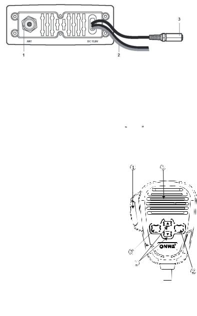
3.2Back panel (connections)
*Warning! Faulty connections or short-circuits may seriously damage KV-300. Before attempting any connections, consult the specialized
sections of this manual.
1.Antenna socket
This SO 239 socket is for connecting an appropriate antenna.
2.Power cable
This red/black cable has to be connected to a power source of 12 Vdc (red is
positive).
3.Socket for additional external loudspeaker/GPS Connection
You can use this jack for the connection to a suitable external loudspeaker (optional),
if needed. |
|
Allows for connection to the optional GPS module KP32 |
(or other compatible |
Receiver Module), for obtaining, viewing and transmitting (with DSC) information regarding position and current time data.
3.3 Microphone
1.UP and DOWN buttons: These two buttons
change the tuning channel. The first scrolls
upwards through the tuned marine channels,
the second scrolls downwards.
2.Button 16: For ease of use, button 16 performs
the same function as the button 16 on the front
panel of the transceiver.
3.MENU: activates the same functions/features
of the MENU button on the front panel of
the radio.
4.PTT (push to talk): Pressing this button will
begin transmission
5.Microphone: During transmission, speak a
few centimetres from the microphone.
MENU |
16 |
|
R |
6
4. INSTALLATION
4.1 Contents of package
Before using your transceiver, ensure that your package is complete and contains:
4
2 5
|
|
8 |
|
6 |
7 |
10 |
11 |
9 |
1.Mounting bracket
2.Mounting pieces for microphone
3.Knobs (2 pieces)
4.Circular film (2 pieces)
5.Self-threading screws for mounting bracket (4 pieces)
6.Screws for the microphone mount (2 pieces)
7.Screws for mounting bracket (2 pieces)
8.Washers (2 pieces)
9.Spring Washers (2 pieces)
10.NUTS (2 pieces)
11. 5Pin Cable for GPS Receiver and external loudspeaker
Black: GND
Red: 5V
Yellow: SPEAKER
Green: NMEA0183 IN+
Blue: NMEA0183 IN-
* Depending on the model, some parts may already be attached/connected to the device.
In any case, if any parts are missing, immediately contact your supplier.
7

4.2 Location for the transceiver
Before continuing, look for a place to install the transceiver which:
Is far enough away from any device sensitive to magnetic/electromagnetic
fields (e.g. compass) in order to avoid interference during their use.
Allows for accessibility to the front panel of KV-300.
Provides easy connection to a power supply, for the antenna and for other
cables.
Has sufficient space close by for installation of the microphone support.
Allows for mounting of the antenna at least 1 meter from the transceiver.
The universal mounting bracket supplied allows for mounting of the transceiver
high up(with the bracket above the device)or on the bridge (with the bracket
below the device) with an angle range of 45 .
*Warning! Installation and connections must be performed in part by qualified persons.
4.3Mounting of transceiver
To mount the transceiver to your vessel (see following picture):
1. |
Choose an appropriate location, as explained in the paragraph above. |
|
2. |
Position the mounting bracket on |
the surface upon which it will be fixed, |
|
use a pencil to draw the position |
of the four holes where the screws will be |
|
inserted. |
|
* |
Ensure that the surface intended |
for the transceiver mounting can be dril- |
led into without provoking damage to other parts of the vessel and be careful
to not drill right through it.
3.Remove the bracket, drill four holes smaller in diameter than the screws, and
reposition the mounting bracket, aligning it with the four holes.
4.Screw in the mounting screws and ensure the bracket is fixed firmly, using the
screws, the Spring washers, the flat washers and the nuts supplied.
If you are not able to reach the back part of the bracket surface to fix the nuts
onto the screws, use threaded screws to fix the bracket.
5.Tighten the screws with a screwdriver so that the bracket is firmly fixed to the
surface.
8
 Loading...