

Page 1

KV-300
˵Ã÷Êé
˵Ã÷Êé
OPERATOR`S MANUAL
VHF DSC MARINE TRANSCEIVER
R
KV-300
Page 2

Page 3

CONTENTS
1. ABOVE ALL... SAFETY! 1
1.1 Symbols used 1
1.2 Warnings 1
1.2.1 General 1
1.2.2 Radio Frequency/Installation 1
1.2.3 Automatic Transmitter Identification System (ATIS) 2
1.2.4 Environmental 2
1.3 ETSI Information 2
1.4 Assistance 2
1.5 Manual Notes 2
2. INTRODUCTION 3
2.1 Generalities 3
3. DESCRIPTION OF CONTROLS AND CONNECTORS 4
3.1 Front panel 4
3.2 Back panel (connections) 6
3.3 Microphone 6
4. INSTALLATION 7
4.1 Contents of package 7
4.2 Location for the transceiver 8
4.3 Mounting of transceiver 8
4.4 Adjustment of angle 9
4.5 Installation of the antenna/electromagnetic exposure 9
4.6 Mounting of Microphone 9
4.7 Connections 10
4.7.1 Power Supply 10
4.7.2 GPS device 10
4.7.3Antenna 10
5. BASIC OPERATION 11
5.1 Turning KV-300 on/off 11
5.2 Volume adjustment 11
5.3 Squelch Regulation 11
5.4 Selecting an operating channel 11
5.5 Transmission and reception 12
5.6 Selecting high and low transmission power 12
5.7 Instant recall of channel 16 12
5.8 Display/keypad lighting 12
6 . SCANNING FUNCTIONS 13
6.1 Channel scanning 13
6.2 Dual Watch and Triple Watch 14
6.3 MEM function 14
Page 4

7. USE WITH GPS 15
7.1 Function 15
7.2 GPS information on the display 15
8. DIGITAL SELECTIVE CALLING (DSC) 16
8.1 Introduction 16
8.2 Mobile Marine Identification Service (MMSI) 16
8.3 Navigating the DSC menu 16
8.4 Individual call (ROUTINE TO) 17Sending
8.5 Group calling (Group Call) 17Sending
8.6 General call to all ships 18Sending
(ALL SHIP SAFETY ALL SHIP )URGENCY
8.7. DSC DISTRESS call 18Sending
8.7.1 Sending a DISTRESS call 18
8.8 Position request 19
8.9 Stand By option 20
9. RECEIVING A DSC CAL 21
9.1 21Receiving a Individual Call
9.2 Receiving a Group Call 21
9.3 22Receiving a General call to all ships(ALL SHIP SAFETY- ALL SHIP URGENCY)
9.4 Receiving a DSC Distress call 22
10. CUSTOMIZATION 23
10.1 Log (list of registered calls) 23
10.2 Dir (Entries in the directory) 23
10.3 GPS 24
10.4 GPS select 24
10.5 Beep (Enable/disable keypad beep) 25""
10.6 Display/keypad backlight 25
10.7 Band edit 25
10.8 LCD contrast 26
10.9 MMSI (Setting of personel MMSI code and MMSI group code) 26
10.10 ATIS (Setting of ATIS code and activation deactivation of""
automatical transmission) 27
11. PROGRAMING AND SELECTION OF PRIVATE CHANNELS 28
12. MAINTENANCE 29
12.1 Maintenance and warnings 29
13. TROUBLESHOTING 30
14. TECHNICAL SPECIFICATIONS: 31
14.1 Transmitter 31
14.2 Receiver 31
14.3 70 Channel receiver 32
14.2 GPS 32
15. FREQUENCY TABLE 33
Page 5

1. ABOVE ALL... SAFETY!
1.1 Symbols used
For ease and convenience of viewing, KV-300 uses symbols to highlight urgent situ-
ations, practical advice, and general information.
*Warnings such as this, shown using an open hand symbol, indicate a crucial
description regarding technical repairs, dangerous conditions, safety warnings,
advice and/or important information. Ignoring these symbols may result in
serious problems and/or damage and/or personal injury.
Notes: such as this one indicate practical advice that we suggest be followed for
optimal performance with KV-300.
1.2 Warnings
1.2.1 General
This device has been tested for compliance with Class D digital marine device
limits. These limits were created to allow for reasonable protection against
damaging interference.
This device is to be used solely as an aid to navigation. Its settings may be
influenced by diverse factors, such as defects or malfunction of the device,
environmental conditions or improper use.
It is the user's responsibility to observe reasonable prudence and judgement in
navigation, and as such this device should not be considered a substitute for
this reasonable prudence and judgement.
Do not open the radio for any reason! KV-300's precision mechanics and
electronics require expertise and specialized equipment; for the same reason,
the radio should under no circumstances be realigned as it has already been
calibrated for maximum performance. Unauthorized opening of the transceiver
will nullify the warranty.
1.2.2 Radio Frequency/Installation
Midland recommends following the requirements for prevention of radiofrequency
exposure. Unauthorized changes or modifications to this device may invalidate
conformity to the ETSI Regulations.
This VHF DSC transceiver generates and irradiates electromagnetic energy (EME)
at radiofrequency (RF), and as such must be installed and placed in operating
conditions that are in conformity with the instructions contained in this manual
and with current regulations. Not following these instructions can cause personal
injury and/or malfunction of the device.
Do not use KV-300 before connecting a suitable antenna that is in perfect
working condition although KV-300 is protected, this may seriously damage
the stages of transmission power.
Do not use transmit before ensuring proper connection of the antenna. During
transmission, remain at a minimum distance of 1mt from the antenna.
1
Page 6

Warning:
User may hold the PTT five minutes, but the device should be placed in inaccess-
ible areas to avoid burns others.
Long-Time emission may shorten the life of the equipment.
1.2.3 Automatic Transmitter Identification System (ATIS)
Your marine transceiver may activate, if necessary, the ATIS function. The ATIS
function may be activated when using the transceiver within the internal navigable
waters of Europe which require the automatic transmission of identification.
For further details, please contact your local authorities.
1.2.4 Environmental
Pay attention to ambient conditions although KV-300 is designed to operate under
the most severe conditions, it is important to avoid exposure to environments that
are excessively humid or dusty, or to temperatures outside the 15 to +55 range.
Also avoid exposure to direct sunlight.
Avoid jarring and excessive vibration KV-300 is built to resist mechanical shock
and vibration as long as these are within the norm for any electrical device.
Do not use this device in potentially explosive environments. A single spark
may cause an explosion.
1.3 ETSI Information
ETSI (European Telecommunications Standards Institute) has established specific
requirements (EN 301 025-2/3) for marine transceivers with DSC function class
For use on non-SOLAS vessels.
1.4 Assistance
We urge you to write the serial number of your transceiver in the space provided
below. This number is found on the back panel of the transceiver and will be
useful in the event of repair/assistance and/or loss and/or theft..
1.5 Manual Notes
Writing of this manual has been completed with the intention of supplying
information that are comprehensive, precise and up-to-date. Nevertheless, the
manufacturer does not assume responsibility for the actual correspondence with the
product and for the consequences of possible errors caused by factors over which it
has no control. Equipment and options described may differ according to varying
countries.
2
Page 7

2. INTRODUCTION
2.1 Generalities
Congratulations for choosing ONWA's marine transceiver KV-300. This product
is a high performance, mobile VHF DSC marine transceiver. The following are its
principle features:
Equipped with all international channels available (correctly assigned).
High transmission power of 25W, which allows the user to maintain contact
from large distances, and a low transmission power of 1W to reduce consump-
tion during short-distance communication.
Principal commands duplicated on the microphone for faster accessibility
channel selection and channel 16 recall.
Back li t LCD display and adjustable contrast constantly shows KV-300's
parameters and settings and occurs an optimal visualization.
Possibility to program 20 private channels by means of the optional
programming kit PRG KV-300 .
is controlled by the national competent authorities: for this reason, we suggest
you contact the local radio communcation authorities.
Extraordinary capability for water resistance,
Industry Standard level JS7 or IPX7.
Recall button for Channel 16 for instant access to channel 16(the universal
marine channel for emergency contact).
NMEA connection use the interface cable supplied for easy connection from
transceiver to optional GPS system, such as KP-32 or other compatible GPS.
Once connected, the display will show the automatically updated coordinates
(latitude and longitude) and time data.
DSC Digital Selective Calling for security on the water and the ability to
make quick calls automatically (the transceiver supports DSC (Digital Selective
Calling) operations with a specifically designed DSC unit which conforms
to the ITU-R standard, M493-11 Class D requirement).
MMSI directory, which simplifies the sending of DSC calls to frequently called
contacts and allows viewing of contact name on the display.
Mounting on adjustable bracket for stable and comfortable positioning In
any condition.
Connection to an external speaker (optional) for listening to communications
further away from the transceiver.
We remind that the use of private channel
conforms to the with Japanses
3
Page 8
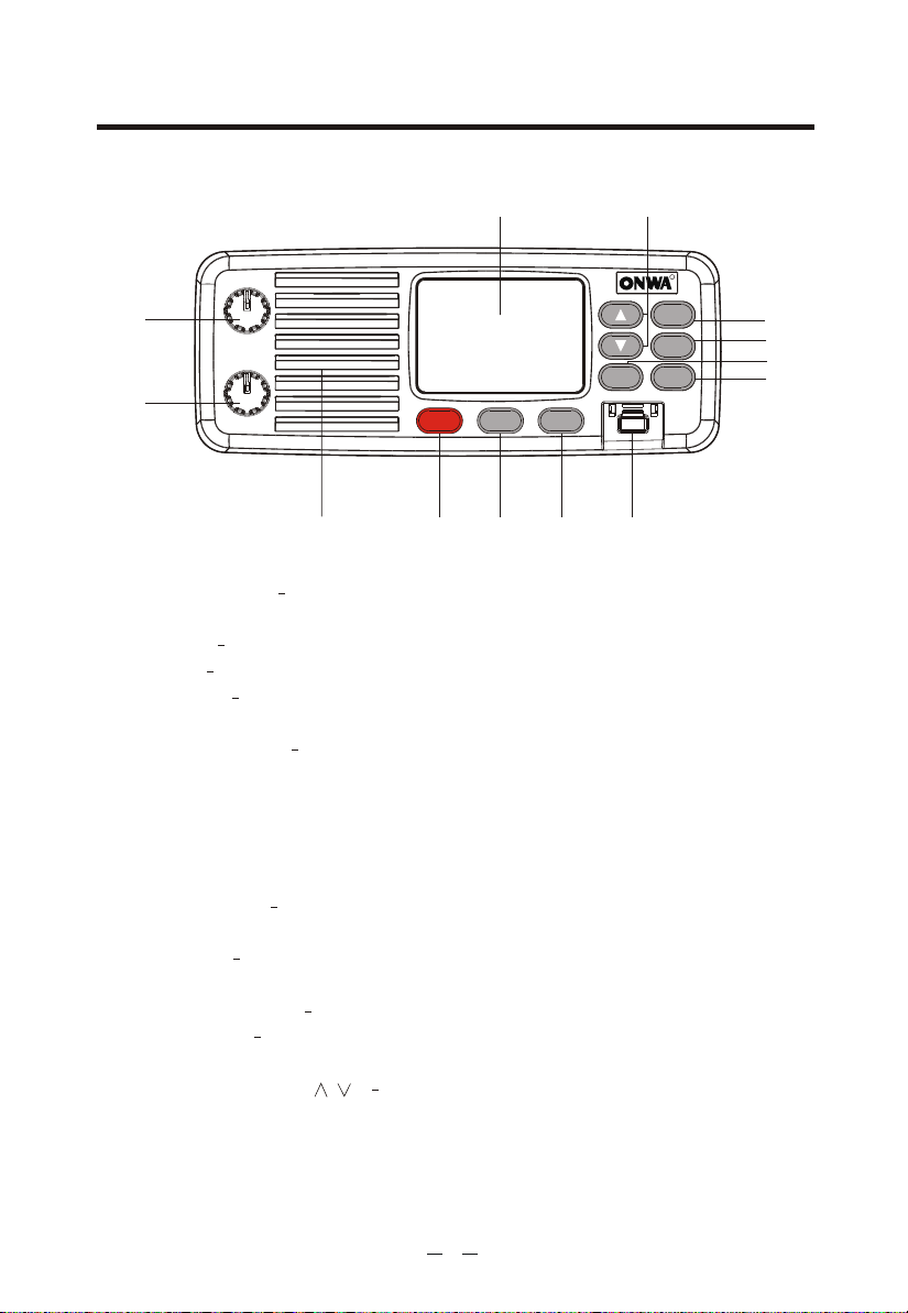
3. DESCRIPTION OF CONTROLS AND CONNECTORS
3.1 Front panel
13
11
RR
MENU
SELECT
KV-300
MEM
STEP
SCAN
TW
10
9
7
8
1
2
OFF
SQUELCH
PWR/VOL
12
Hi/LOW DW
16
3 4
5 6
1. PWR/VOL - Turns KV-300 on/off and regulates audio volume reception.
2. SQUELCH knob Regulates the squelch level (noise silencer in absence of
signals).
3. Button 16 Pressing the 16 button provides quick access to channel 16.
4. Hi/LOW To select the high or low transmission power.
5. DW button This button activates the Dual Watch function, able to monitor
two channels of your choice.
6. DISTRESS button The button below a soft cover sends a DISTRESS call for
help. The signal also includes your MMSI identification code and the nature of
the distress. If a GPS is connected to the device, data regarding position and
time are also included in the call.
* The Distress function,or any other DSC transmission function,is not operative
until a MMSI user code has been inserted.
7. MENU/SELECT Toenter the menu of the radio and confirm the selected
settings.
8. T/W button Activates the Triple Watch function, able to monitor 3 different
channels.
9. STEP/SCAN button To select two different types of scanning.
10. MEM button Allows to store the selected channel and insert it in t he
memory group.
11. UP/DOWN controls / They are useful to look through the menu and
to select the channels.
12. Internal speaker - Guarantees clear listening of communications.
4
Page 9
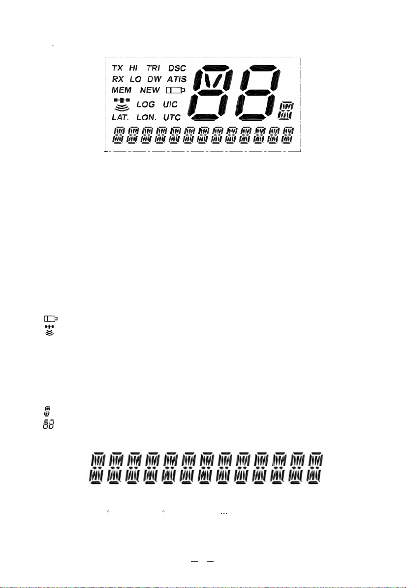
13 LCD Symbols and Meanings:
This simulation shows the locations of all the following information symbols:
Symbol Meaning
TX Transmitting
HI LOTransmission power.(HI)25W or LOW(LO) 1W
RX Receiver Busy with an incoming singal
TRI Triple Watch function
DW Dual Watch function
DSC DSC capability is available
ATIS KV300(EU only),and enabled for radio in European inland
waterways.
MEM Memory
NEW New address
Low Battery warning (activates at 10.5v)
GPS receiver icon
LOG List of registered calls
UIC Selected channel band(USA-INT-CAN) for VHF radio
operations and regulation
LAT. Lat itude
LON. Long itude
UTC Universal Time Coordinated
Channel Suffix if applicable
Channel Selected
A type operational display is showen here.
The latitude and longitude of the vessel and the local time are shown.
Indicate: LAT.99 99 LON.999 99 .88:88. Etc
5
Page 10
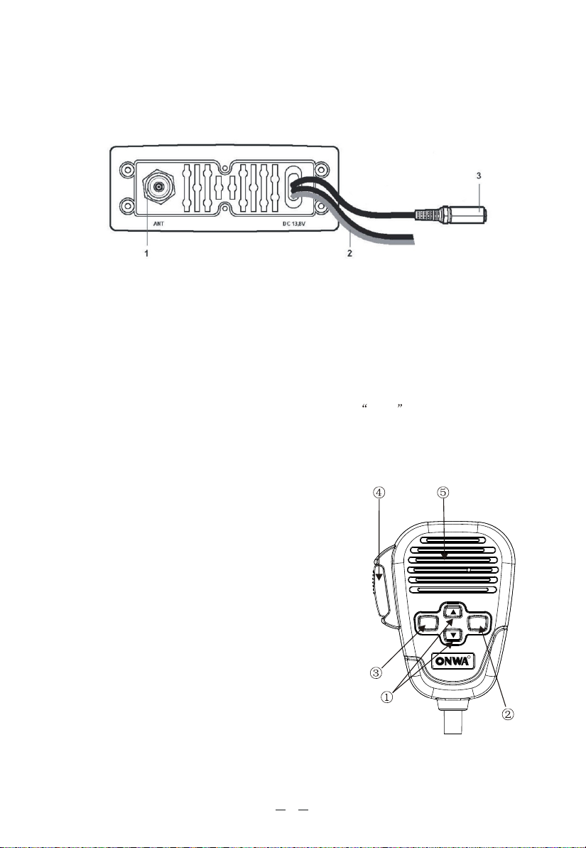
3.2 Back panel (connections)
* Warning! Faulty connections or short-circuits may seriously damage
KV-300. Before attempting any connections, consult the specialized
sections of this manual.
1. Antenna socket
This SO 239 socket is for connecting an appropriate antenna.
2. Power cable
This red/black cable has to be connected to a power source of 12 Vdc (red is
positive).
3. Socket for additional external loudspeaker
/GPS Connection
You can use this jack for the connection to a suitable external loudspeaker (optional),
if needed.
Allows for connection to the optional GPS module KP32 (or other compatible
Receiver Module), for obtaining, viewing and transmitting (with DSC) information
regarding position and current time data.
3.3 Microphone
1. UP and DOWN buttons: These two buttons
change the tuning channel. The first scrolls
upwards through the tuned marine channels,
the second scrolls downwards.
2. Button 16: For ease of use, button 16 performs
the same function as the button 16 on the front
panel of the transceiver.
3. MENU: activates the same functions/features
of the MENU button on the front panel of
the radio.
4. PTT (push to talk): Pressing this button will
begin transmission
5. Microphone: During transmission, speak a
few centimetres from the microphone.
MENU
16
R
6
Page 11
4. INSTALLATION
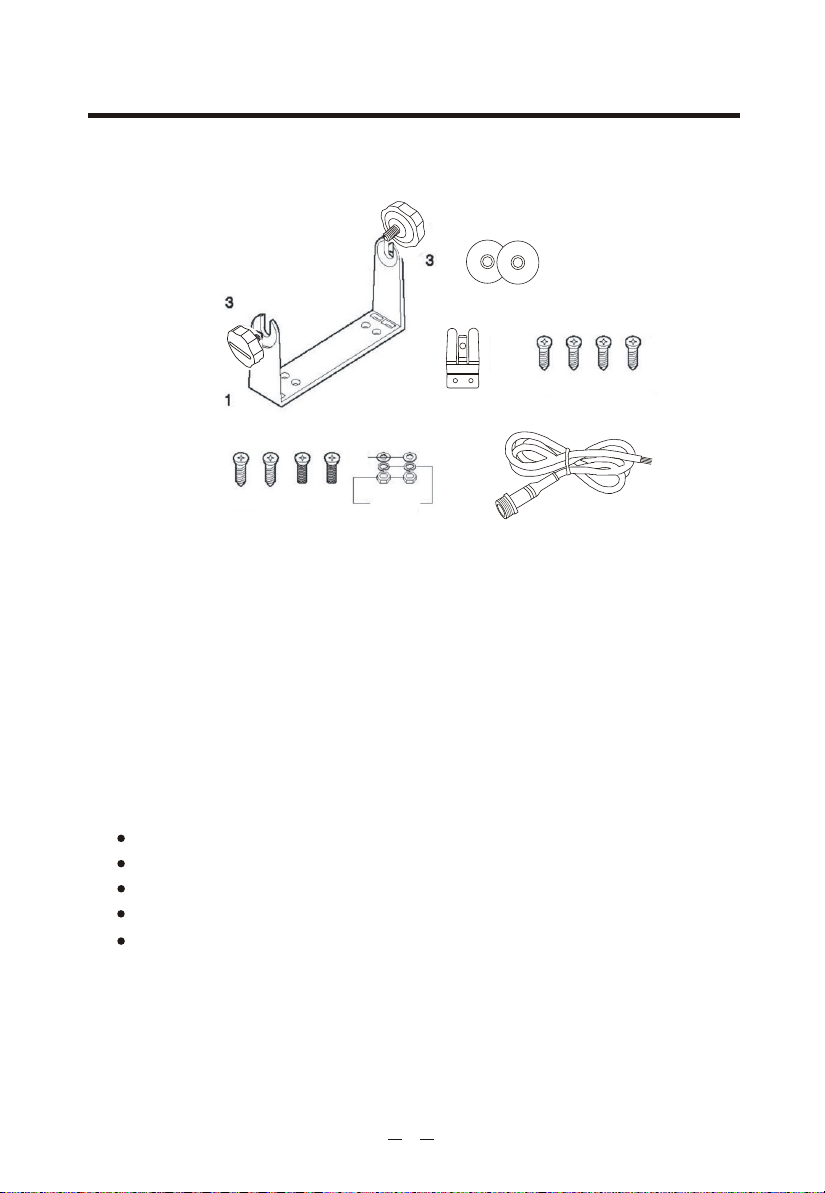
4.1 Contents of package
Before using your transceiver, ensure that your package is complete and contains:
4
2
8
6 7
910
1. Mounting bracket
Mounting pieces for microphone
2.
3. Knobs (2 pieces)
4. Circular film (2 pieces)
Self-threading screws for mounting bracket (4 pieces)
5.
Screws for the microphone mount (2 pieces)
6.
7. Screws for mounting bracket (2 pieces)
8. Washers (2 pieces)
9. Spring Washers (2 pieces)
NUTS (2 pieces)
10.
5Pin Cable for GPS Receiver and external loudspeaker
11.
Black: GND
Red: 5V
Yellow: SPEAKER
Green: NMEA0183 IN+
Blue: NMEA0183 IN-
5
11
* Depending on the model, some parts may already be attached/connected to the device.
In any case, if any parts are missing, immediately contact your supplier.
7
Page 12
4.2 Location for the transceiver
Before continuing, look for a place to install the transceiver which:
Is far enough away from any device sensitive to magnetic/electromagnetic
fields (e.g. compass) in order to avoid interference during their use.
Allows for accessibility to the front panel of KV-300.
Provides easy connection to a power supply, for the antenna and for other
cables.
Has sufficient space close by for installation of the microphone support.
Allows for mounting of the antenna at least 1 meter from the transceiver.
The universal mounting bracket supplied allows for mounting of the transceiver
high up(with the bracket above the device)or on the bridge (with the bracket
below the device) with an angle range of 45 .
* Warning! Installation and connections must be performed in part by
qualified persons.
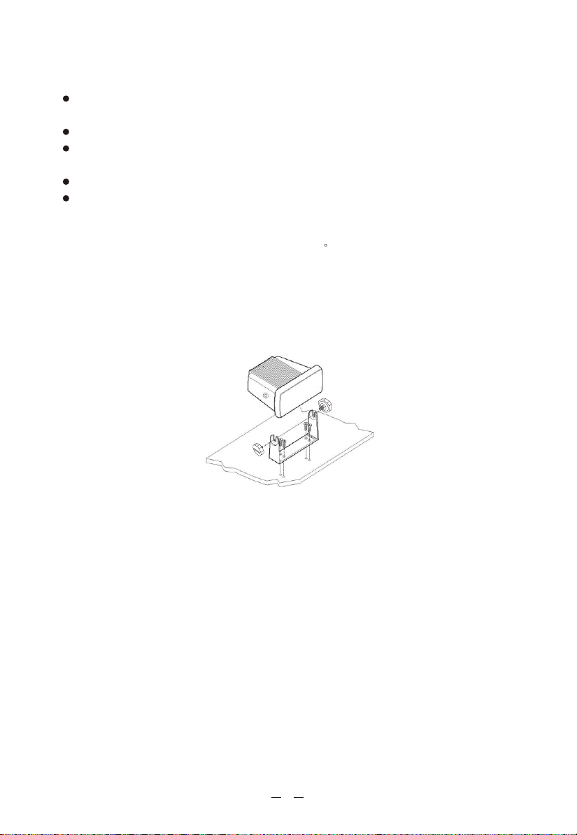
4.3 Mounting of transceiver
To mount the transceiver to your vessel (see following picture):
1. Choose an appropriate location, as explained in the paragraph above.
2. Position the mounting bracket on the surface upon which it will be fixed,
use a pencil to draw the position of the four holes where the screws will be
inserted.
* Ensure that the surface intended for the transceiver mounting can be dril-
led into without provoking damage to other parts of the vessel and be careful
to not drill right through it.
3. Remove the bracket, drill four holes smaller in diameter than the screws, and
reposition the mounting bracket, aligning it with the four holes.
4. Screw in the mounting screws and ensure the bracket is fixed firmly, using the
screws, the washers, the flat washers and the nuts supplied.
Spring
If you are not able to reach the back part of the bracket surface to fix the nuts
onto the screws, use threaded screws to fix the bracket.
5. Tighten the screws with a screwdriver so that the bracket is firmly fixed to the
surface.
8
Page 13

6. Align the transceiver on the bracket, ensuring the holes of the internal part of
the bracket line up with those on both sides of the transceiver (you can choose
the preferred notch in order to best adjust the angle of the transceivers front panel
for ease of viewing and use (150 of variation for each notch).
7. Mount the mounting knobs on the two sides of the bracket to soundly fix the
transceiver. Keep the transceiver and microphone at a distance of at least 1
meter from all other magnetic devices (e.g. compass) on your vessel.
4.4 Adjustment of angle
To change the angle of inclination after installation:
1. Loosen the mounting knobs on the sides of the bracket.
2. Adjust the transceiver to a better angle, lining up the holes of the internal part
of the bracket with those on both sides of the transceiver.
3. Tighten the knobs to fix the transceiver into place.
4.5 Installation of the antenna/electromagnetic exposure
For optimal radio settings and minimal user exposure to electromagnetic
radiofrequency energy, ensure that:
The antenna is connected to the transceiver and is properly installed.
The antenna is situated away from people and is positioned at least one meter
from the transceiver and microphone.
The connector is a standard PL259 (male UHF).
4.6 Mounting of Microphone
To mount the microphone mount, look first
for a mounting point close to the transceiver.
The distance between the transceiver and the
wall mount must be less than the length of
the microphone cable.
Do not pull excessively on the microphone cord.
This part is important to the correct function
of the device: over time, pulling may damage
the cord and impede the user from transmitting.
9
R
Page 14

4.7 Connections
Refer to the following diagram:
Fuse
12 Vcc
Black
-
Power supply
Hi/LOW DW
16
External speaker
GPS receiver
RR
MEM
STEP
SCAN
MENU
TW
SELECT
KV-300
Antenna
Red
+
Passage to
bronze seal
OFF
PWR/VOL
SQUELCH
4.7.1 Power Supply
The transceiver power supply must be 12Vdc. The red cable must be connected to
the positive pin, the black to the negative pin.
Warning! A faulty connection may seriously damage the radio!!
The power cable is equipped with a protection fuse. If the fuse shorts, look for its
reason before substituting the cable with a new one of the same type and value.
Never short circuit it, as this may damage the radio. We suggest using the sup-
plied cable.
4.7.2 GPS device
If your KV-300 transceiver is connected to a GPS receiver such as the
KP32, you can obtain and view NMEA information relative to the current position
the vessel (latitude and longitude) and the local time with respect to Green-
wich Mean Time (GMT).
Module,
4.7.3 Antenna
The antenna is an extremely important part of the device and noticeably influences
the settings of any telecommunications device. Contact your supplier regarding
the antenna and request advice about how to mount and best connect it to your
transceiver.
Warning! Ensure the antenna is in perfect working order. It may otherwise
seriously damage the radio! A periodical measurement of the stationary
waves is advised using a suitable SWR metre.
10
Page 15

5. BASIC OPERATION
5.1 Turning KV-300 on/off
To turn the transceiver on, rotate the PWR/VOL knob clockwise until it clicks on.
You will hear a beep(acoustic signal)and the LCD display will show the channel
in use.
Important: when you turn on the radio for the very first time, the display will
show channel 16; while usually, KV-300 stores the last channel in use before it's
switched off. To turn the transceiver off, rotate the knob counter-clockwise until
you hear a click.
5.2 Volume adjustment
Bring the OFF/VOLUME knob first to medium volume.Once the transceiver picks
up a signal, adjust the volume t o a comfortable level. If no signal is picked up,
use the squelch control as described in the following paragraph and regulate the
volume using the background noise.
5.3 Squelch Regulation
Squelch is used to eliminate the annoying background noise you hear when no
signal is being picked up. If the squelch is adjusted correctly, there should be
silence in between calls as well as a reduction in battery consumption. To regulate
the squelch:
1. Rotate the SQUELCH knob completely counter-clockwise until you hear the
background noise (if you don't hear anything, increase the volume); RX
will appear on the display.
2. If no signal is being received (only noise), slowly rotate the SQUELCH
knob clockwise,stopping as soon as the noise and RX disappear stably.
If you regulate the squelch level too high (closed), you may hear only
background noise or intermittent discharges.
5.4 Selecting an operating channel
Press repeatedly the UP or DOWN buttons on the keypad or on the microphone
to scroll through the marine channels until finding the desired channel.
Channel 16 is dedicated to the emergencies, therefore we recommend not to use
it for general communications!
Channel 70 is dedicated to DSC communications.
11
Page 16

5.5 Transmission and reception
Transmitting without a perfectly functioning antenna may seriously damage
the transceiver.
The PTT (Push-To-Talk) button is located on the external microphone of your
KV-300. To transmit:
1. Ensure that no one else is speaking.
2. Hold down the PTT button on the microphone. TX will appear on the Display.
Wait for a second, then speak in a normal voice about 5 cm from the
microphone.
3. When you have finished, release the PTT button: TX will disappear from the
display. Now KV-300 is in receiving mode (silent and waiting for a signal)
and will automatically receive any communication.
5.6 Selecting high and low transmission power
The transmission phase absorbs the most energy. To reduce the risk of wearing
out the battery, we recommend selecting low transmission power when transmitting over short distances. Hold the H/L button down (on the radio): Lo (low
power) appears on the display. When transmitting or receiving over long distances
or with weak signals, press the H/L button again. Lo will be replaced with Hi
(high power) on the display.
When the transceiver is tuned to a channel limited to low output power, pressing
the H/L button has no effect.
5.7 Instant recall of channel 16
Channel 16 is a security and distress channel. This channel is used for emergency
communications.
Press the 16 button (the red one on the keypad) and you will be tuned on the
emergency channel.
To return to the channel previously used, simply press the 16 button again.
Do not transmit on channel 16 unless absolutely necessary. Doing so may
impede emergency operations.
5.8 Display/keypad backlight
The display/keypad backlight can be adjusted according to your needs or to the
environmental conditions.
To select the desired level of backlight:
K
eep pressed MENU/SELECT until DSC CALL appears on the display;
U
sing the UP/ DOWN buttons select SYSTEM and confirm pushing
MENU/SELECT;
S
elect BACKLIGHT and confirm by pushing MENU/SELECT;
S
elect the desired backlight level, from 0 to 3.
To return to the radio modality, push PTT, select EXIT in every menu, or wait for
minute
1 and the radio will automatically exit .
12
Page 17

6. SCANNING FUNCTIONS
6.1 Channel scanning
KV-300 can automatically search for signals throughout the marine band by
scanning, or selecting the channels in rapid sequence. When a signal is detected,
the scanning pauses on that channel ( RX displayed) and remains blocked until
the signal ends. Before the scanning automatically starts ag ain, KV-300 waits
for a 3,4 seconds in case the user wants to transmit.
You can transmit in any moment, even if the scanning is active. In this case,
the transmission will be done on the channel currently scanned; but if you
transmit just after a signal is detected, the radio will transmit on that channel.
After the transmission, the scanning is interrupted.
If the scanning detects an undesired channel, you can start scanning again by
pushing STEP/SCAN.
To activate the Scan function:
Hold down the STEP/SCAN button till scan on the display;
Press MENU/SELECT to confirm your selection. The scanning will start.
To stop the SCAN, then press the STEP/SCAN button.
The scanning and the memory scanning cannot properly work if the squelch is
not adjusted as previously described.
To activate the Mem Scan function:
Pressed STEP/SCAN till MEM appears on the display;
MEM scanning will start.( Now the scanning of the stored channels starts.)
To stop it, push STEP/SCAN and the radio will stop on the channel scanned in
that moment.
Reception: if KV-300 detects a signal, the scanning interrupts and the display
indicates RX .
Transmission: you can transmit in any moment,even if the scanning is active.
In this case, KV-300 will transmit from the channel being scanned in that
moment; but if the t ransmission is done after a channel is picked up, the
device will transmit from that channel within 3 / 4 seconds. After the transmi ssion, the scanning interrupts.
13
Page 18

6.2 Dual Watch and Triple Watch
Dual Watch
Allows you to monitor two channels at the same time: the channel in use and
channel 16 (emergency channel).
With the UP / DOWN keys to choose the right channel
To activate this function, push DW and the radio will start monitoring both
channels.
To disable this function push DW again and the radio will return to the channel
in use.
If you push PTT the scanning will stop and the radio will go to channel 16.
The Dual Watch and Triple Watch stop when a signal is picked up, giving
you the possibility to answer.
These functions cannot operate properly if the squelch is not adjusted.
Triple Watch
This function allows the monitoring of three channels at the same time: channel
16, channel in use and one channel of your choice.
Procedure:
Press T/W, until TRIPLE WATCH blinks on the display;
Select the secondo channel you want to monitor; CH16 is automatically
monitored;
Confirm by pushing T/W again; the scanning of the 3 channels will begin.
To stop it, press T/W and the radio will automatically return t o the second
channel selected.
If you push PTT the scanning will stop and the radio will go to channel 16.
The Dual Watch and Triple Watch stop when a signal is picked up, giving you
the possibility to answer.
These functions cannot operate properly if the squelch is not adjusted.
6.3 MEM function
This function allows you to store some channels to scan through the Mem Scan
function. To store a channel, follow these steps:
Select the channel to store: keep pressed the MEM button till the display
shows mem.
Repeat the same procedure to store other channels.
To delete a pre-selected channel in memory:
Select it and keep pressed MEM button till mem disappears from the display.
The other stored channels can be easily monitored through the MEM SCAN
function.
The MEM SCAN function cannot properly work if the squelch is not correctly
adjusted
14
Page 19

7. USE WITH GPS
7.1 Function
If connected to a GPS the transceiver will display the
vessel position (latitude and longitude), as well as time data.
If the information regarding position data are not received in the normal radio
mode and the time data does not appear wit hin 4 hours, a 30-second-long
warning tone will sound (can be deactivated by pressing any button).
The display will show POSITION IS OVER 4 HOURS OLD .
You may also insert the coordinates manually.
7.2 GPS information on the display
Once connected the GPS (KP32) to your KV-300 (PS 2 connector), the symbol
will the Lcd display till your position will be established.
Then, the radio display will show theGPS coordinates and the time data.
receiver Module (KP32),
15
Page 20

8. DIGITAL SELECTIVE CALLING (DSC)
8.1 Introduction
Digital Selective Calling is a semiautomatic method for controlling VHF, MF and
HF radio calls. It was also designed as part of the Global Marine
Safety system(GMDSS).
on emergency frequencies and will be used to send urgent and routine radio-
transmitted maritime security information. This new service will allow crafts to
send/receive calls of an emergency, urgent, security, or routine nature to/from
vessels equipped with a DSC transceiver.
To avoid accidentally sending a distress call or a call sent incorrectly, contact
your vendor or local authorities for updates on DSC operating and emergency
procedures.
It is likely that DSC will eventually replace audio calls
8.2 Mobile Marine Identification Service (MMSI)
Important! To send/receive DSC calls, the user must program his personal MMSI
code into the transceiver. This is a nine-digit number used by marine transceiv-
ers equipped for DSC digital selective calling. This number is used much like a
telephone number for contacting other, specific vessels.
DSC transmissions can be done only if you have been assigned the individ-
ual MMSI code and you entered it in your radio(otherwise the Distress/DSC
controls will be disabled).
Sending a distress call without founded reason is a criminal offence. Never use
this function unless you find yourself in a situation that merits asking for help.
Distress and
8.3 Navigating the DSC menu
KV-300 offers many DSC function .For this reason it was created.
Once inside a sub-menu, you can return at any time to the main menu by pressing
the PTT button.
To return to the radio mode, confirm EXIT in every menu.
16
Page 21

8.4 Individual call (ROUTINE TO)Sending
The user can carry out an individual call to a specific DSC station (a vessel or a
coastal station).
To carry out calls, you have to enter the MMSI code manually or recall it
from the preprogrammed MMSI directory.
Keep pressed MENU/SELECT till DSC CALL is displayed;
Confirm your selection by pushing MENU/SELECT; the display will show
INDIVIDUAL. Push MENU/SELECT again for confirmation;
Now you can choose whether inserting the MMSI code manually or recall it
from the directory previously set
Scroll with the UP/DOWN keys the 9 digits composing the code;
Confirm by pushing MENU/SELECT;
With the UP/DOWN keys select one of the 23 channels available (simplex) and
confirm your selection with MENU/SELECT. Display will jump to the selected
channel interface, the following shows the "SEL SEND CH"
Confirm by pushing MENU/SELECT, The transmission is sent and WAITING
ACK will on the display;
if your call is confirmed by the other party, the display shows his name
INDIVIDUAL ROUTINE FROM MMSI ON CHANNEL 6 (OTP) and you will
hear a beep.
If you push MENU/SELECT the display indicates the channel previously
selected and the beep will stop; instead if you push any other channel, you will
exit the individual call.
8.5 Sending Group calling (Group Call)
This function allows the user to call a specific group of stations which have the
same MMSI group code stored in their transceivers and which signals the audio
channel the user wishes to speak on.
Therefore you can only carry out the group call when you have programmed the
addresses in a directory.
Keep pressed MENU/SELECT till DSC CALL is displayed;
Confirm by pushing MENU/SELECT; INDIVIDUAL will appear on the display;
Scroll through the channels with the UP/DOWN keys;
Select GROUP and confirm the selection with the MENU/SELECT button;
You will be asked the code previously set; after this selection, confirm by
pushing MENU/SELECT;
Select one of the 23 channels available, send the call and press MENU/SELECT
as confirmation.
17
Page 22

8.6 Sending a call to all ships
(ALL SHIP SAFETY ALL SHIP URGENCY)
Keep pressed MENU/SELECT till DSC CALL is displayed;
Confirm by pushing MENU/SELECT;
Scroll through the channels with the UP/DOWN keys;
Select ALL SHIP and push MENU/SELECT as confirmation;
Select ALL SHIP SAFETY with the UP/DOWN keys and push MENU/SELECT;
Select the desired channel and send the call by pushing MENU/SELECT;
To send an ALL SHIP URGENCY call, repeat the above described procedure
except the channel selection which is not required (the DSC is automatically
sent to channel 16).
Sending a distress call without founded reason is a criminal offence.
Never use this function unless you find yourself in a situation that merits
requiring help.
Sending
8.7 DSC DISTRESS call
8.7.1 Sending a DISTRESS call
IMPORTANT! You can only send a DSC call if you have been assigned an
individual MMSI code and this code has been programmed into the transceiver
(otherwise the following commands will be deactivated).
Sending a distress call without founded reason is a criminal offence.
Never use this function unless you find yourself in a situation that merits
requiring help.
The DISTRESS button is protected by a small plastic shutter.
This button activates preset emergency messages which are transmitted on a
dedicated channel, channel 70.These messages are sent to all the radios operating
within your range and may be sent also to a busy channel.
To activate a Distress call: raise the shutter, press DISTRESS and choose, with
the UP/DOWN keys, the desired message amongst these:
A. UNDEFINED
B. ABANDONING
C. PIRACY
D. M.O.B. (man over board)
E. FIRE
F. FLOODING
G. COLLISION
H. GROUNDING
I. LISTING
L. SINKING
M. ADRIFT
N.EPIRBEMISSION
18
Page 23

Hold down DISTRESS KEY for 5 seconds as confirmation.
An acoustic alert sign will emit(70CH)and the distress call will be
carried out.
While the screen displays "WAIT FOR ACK KEEP PRESS16 TO CANNEL"
Click the 16 keys, LCD display "CANNEL DISTRSEE" while 70 channels
transmit a reply message, the alarm sound disappeared, returned 16
channel display.
If the distress call is received and confirmed by another station, the
alert sign will stop and the display will return to normal use in VHF
model on channel 16 (70CH sending on high transmission power.)
If no confirmation is received,the unit will send again the distress call
at intermission of 4 minutes (even with channel 70 in use) until a
confirmation is received .
User manually cancel the call through press 16 (distress cancell)
buttons or PTT With the UP/DOWN keys scroll through the digits and
insert UTC
8.8 Position Request
It is possible to send a DSC call to requie the position of a DSC station
(it may be preset in the directory or manually inserted).
Hold down the MENU/SELECT key till the display indicates DSC CALL
Press MENU/SELECT as confirmation
Scroll through the channels with the UP/DOWN keys
Select POS REQUEST and confirm by pushing MENU/SELECT
You will be asked a MMSI code, which may be manually inserted or
found in the directory
Select MANUAL INPUT or DIRECTORY with the UP/DOWN keys
Insert the code with the UP/DOWN keys (in case of manual selection)
and press MENU/SELECT as confirmation
The request will be sent to the selected DSC station and the display will
show WAITING ACK.
19
Page 24

8.9 STAND BY option
Every time a DSC call is received, you can manually choose whether
accept or refuse it.
If you activate the Stand By option, the radio will automatically refuse
the incoming calls (individual, group call, all ship safety, position request)
Hold down MENU/SELECT till DSC CALL appears on the display
Press again MENU/SELECT as confirmation
With the UP/DOWN keys, select STAND BY, and confirm with MENU/
SELECT.
Select ON if you want to refuse automatically the incoming calls
Select OFF to manually answer to incoming calls.
Confirm by pushing the MENU/SELECT button.
To return to the radio mode, push PTT, select EXIT in any menu or wait
for 1 minute and the radio will automatically exit.
20
Page 25

9. RECEIVING A DSC CALL
When the user receives a DSC call, the transceiver will automatically respond
according to the type of call.
Information shown on the LCD display will vary according to the type of call.
Receiving a individual call
9.1
When the transceiver receives an individual call, it automatically move to the
channel indicated by the DSC signal and emits a tone to alert the user of an
incoming call.
LCD Display scrolls INDIVIDUAL ROUTINE FROM 888888888 (MMSI) ON
CHANNEL 6(OTP)
The pressure to the function key MENU/SELECT will deactivate the alarm
and display While the other replies CALL
EXIT press 16 to exit or PTT.
The MMSI owner code contained in the signal appears on the display.
When you hear the alarm sound, with UP / DOWN keys to select "DISABLE ACK"
and "ENABLE ACK" If you select ENABLE, Press MENU / SELECT confirm, transmitting a return signal to the caller, the device automatically go to work can be
normal call channels (channels with the other settings), if you choose DISABLE,
Press MENU/SELECT confirm, the device automatically go to the original work
can be normal call channel.
If the MMSI owner code has been programmed previously with name in the directory, the name of the caller appears too.
Every time KV-300 receives a individual call an entry will be stored in the list of
registered calls LOG .
""
"
"
9.2 Receiving a Group call
When the transceiver receives a GROUP call ,an acoustic alaem will sound, the
LCD displays "GROUP CALL FROM MMSI ON CHANNEL 6(OTP)
The pressure to the function key MENU/SELECT will deactivate the alarm and
display
The display will jump to the corresponding channel
After receiving the alarm ,EXIT press 16 to exit or PTT
Every time KV-300 receives a GROUP call an entry will be stored in the list of
registered calls "LOG".
21
Page 26

Receiving a General call to all ships (ALL SHIP SAFETY-
9.3
ALL SHIP URGENCY)
When the transceiver receives a ALL SHIP SAFETY and ALL SHIP URGENCY,
an acoustic alaem will sound, and the LCD displays "ALL SHIP SAFETY FROM
MMSI "
The pressure to the function key MENU/SELECT will deactivate the alarm and
or ALL SHIP URGENCY From MMSI
display
Safety call to set the display will jump to the other side channels, Urgency call
display will jump to 16 channels
After receiving the alarm,EXIT Press 16 or PTT
Every time KV-300 receives a General call to all ships(ALL SHIP SAFETY- ALL
SHIP URGENCY) call an entry will be stored in the list of registered calls "LOG".
9.4 Receiving a distress call
When the transceiver receives a distress call, an acoustic alarm will sound.
LCD scrolls "DISTRESS MESSAGE FROM 888888888 (MMSI)"
The pressure to the function key MENU/SELECT will deactivate the alarm.
Press UP/DOWN key to view DISTRESS information if the other party to cancel
the DISTRESS, LCD displays "DISTRESS CANCEL ALERT FROM MMSI"
Every time KV-300 receives a Distress call an entry will be stored in the list
of registered calls "LOG".
When the signal also includes position and time data, these information will
appear on the display.
If no position and time data are included in the signal, the display will indicate
99 99 9 99 99 8 8 :88.
22
Page 27

10. CUSTOMIZATION
10.1 Log (list o f r egistered c alls)
With this menu you can consult a directory of the latest registered incoming
calls, like you do with your cellular phone.
Hold down MENU/SELECT till the display shows DSC CALL
Push MENU/SELECT as confirmation
Select LOG, with the UP/DOWN keys and confirm pushing MENU/SELECT
again
Now you can see the list of the latest incoming calls.
To get further information select the desired message by pushing MENU/SELECT;
coordinates, time and sender ID will be shown.
In radio mode, the display indicates LOG
When it s fixed, indicates that some messages are present in the register of the
latest calls; if it blinks, indicates that there are some messages which have not
been read yet.
'
10.2
You can insert into the directory the MMSI codes from frequently called stations,
by giving them a name (e.g. vessel or owner). Then you can search and use them
more comfortably. When receiving a call, the MMSI owner name instead of the
MMSI code will be displayed.
To add new MMSI codes follow this procedure:
SELECT again
to cancel all of them.
If you push again the UP/DOWN buttons you will see the addresses previously
stored.
Confirm the function you want to select (NEW - DELETE ALL)
Scroll the UP/DOWN keys to insert a new name.
Hold down MENU/SELECT to insert the ID identifier code.
To return to radio mode, push PTT, select EXIT in every menu or wait for 1 second
and the radio will automatically exit.
Dir (Entries i
Hold down MENU/SELECT till DSC CALL is displayed
Select SET UP with the UP/DOWN keys and confirm by pushing MENU/
Select DIR with the UP/DOWN keys and push MENU/SELECT as confirmation
With the UP/DOWN buttons, select: NEW for new addresses and DELETE ALL
n
t
he d
irectory)
23
Page 28

To modify some addresses repeat the above described procedure till the display
shows the address to change. Now press MENU/SELECT.
Select EDIT to change the name or code.
Select DELETE to cancel that address.
You can store up to 16 addresses. If the directory is fulled up, Full will appear
on the display, you cannot add further addresses. In this case it is necessary
to cancel some.
10.3
Coordinates (latitude and longitude) can be manually inserted without any conn-
ection to a GPS antenna. Follow these steps:
SELECT button
scrolling the digits with UP/DOWN
modified by pushing MENU/SELECT and scrolling the digits with UP/DOWN
GPS
Keep pressed MENU/SELECT until the display indicates DSC CALL
Scroll through the functions and select GPS;
Latitude and longitude may be modified by pushing MENU/SELECT and
UTC (Universal Time Coordinate) Tempo Universale Coordinato) may be
Confirm by pushing MENU/SELECT
Confirm with the MENU/
With the UP/DOWN keys scroll through the digits and insert UTC
To return to radio mode, press PTT, select EXIT which is present in every menu
or wait for 1 minute and the radio will automatically exit.
For a better efficiency of the DSC service, we suggest you insert coordinates and
time. If KV-300 is connected to a compatible GPS receiver Module, the setting of
these data is not compulsory.
10.4
KV-300 is compatible with almost all the GPS receivers available on the
market. Verify the compatibility with your receiver.
GPS receivers use different strings; in the KV-300 menu you can enable/disable
many types of strings.
According to your needs, select the desired string following this procedure:
Strings are all active by default, therefore you have to disable the undesired
ones.
Select it with UP/DOWN keys and confirm by pushing MENU/SELECT.
Select ON or OFF and confirm.
Data Input Format(GPGGR,GPRMC,GPGNS,GPGLL)
To return to radio mode, push PTT, select EXIT in every menu or wait for 1
Minute
GPS SELECT
Hold down MENU/SELECT until DSC CALL appears on the display
Scroll the list of functions with the UP/DOWN keys
Select GPS SELECT and confirm by pushing MENU/SELECT
and the radio will automatically exit.
.
24
Page 29

10.5 Beep (Enable/disable keypad beep)
Everytime a button is pressed, the radio emits a signal as confirmation or to
warn about wrong operations.
To disable these beeps, follow this procedure:
Hold down MENU/SELECT until DSC CALL appears on the display
Scroll the list of functions with the UP/DOWN keys
Select SYSTEM and confirm by pushing MENU/SELECT
Scroll the list of functions with the UP/DOWN keys
Select KEY BEEP and confirm by pushing MENU/SELECT
if this function is active, on the display ON will appear; while if it's disabled,
the display will show OFF. Select the desired setting.
To return to radio mode, push PTT, select EXIT in every menu or wait for 1
second and the radio will automatically exit.
10.6 Display/keypad backlight.
According to the environmental conditions you can adjust the display/keypad
backlight.
Hold down MENU/SELECT until DSC CALL appears on the display
Scroll the list of functions with the UP/DOWN keys
Select SYSTEM and push MENU/SELECT as confirmation
Scroll again the list of functions with the UP/DOWN keys
Select BACK LIGHT and confirm by pushing MENU/SELECT.
Choose the desired backlight level (from 0 to 3).
To return to radio mode, push PTT, select EXIT in every menu or wait for 1
and the radio will automatically exit.minute
10.7 Band Edit
This function may be activated only with the optional programming kit PRG
KV-300.
It allows the selection of the following bands:
USA-CANADA-INTERNATIONAL (default)
Hold down MENU/SELECT until DSC CALL appears on the display
Scroll the list of functions with the UP/DOWN keys
Select SYSTEM and push MENU/SELECT as confirmation
Select BAND EDIT and push MENU/SELECT as confirmation
Scroll the list of functions with the UP/DOWN keys
Set up: BAND: USA-CANADA-INTERNATIONAL (default)
25
Page 30

10.8 LCD contrast
The user can adjust the display contrast to optimise visibility according to ambient
conditions. To change this setting:
Hold down MENU/SELECT until DSC CALL appears on the display
Scroll the list of functions with the UP/DOWN keys
Select SYSTEM and confirm by pushing MENU/SELECT
Scroll again the list of functions with the UP/DOWN keys
Select LCD Adjust and push MENU/SELECT as confirmation
Choose the desired level, from 0 to 7.
To return to radio mode, push PTT, select EXIT in every menu or wait for 1
and the radio will automatically exit.Minute
10.9 MMSI (Setting of personal MMSI code and MMSI
group code)
This function allows the user to insert their personal MMSI identification code
assigned by an appropriate authority.
Be careful to insert the correct personal MMSI code. Once the code has been
saved, it cannot be modified.
Hold down MENU/SELECT until DSC CALL appears on the display
Scroll the list of functions with the UP/DOWN keys
Select SET UP and confirm by pushing MENU/SELECT.MMSI will be displayed.
Scroll the alphanumerical list with the UP/DOWN keys and digit your own
MMSI code.
Follow the same procedure to insert the MMSI group code but select GROUP
MMSI instead of your own MMSI code.
Hold down MENU/SELECT until DSC CALL appears on the display
Scroll the list of functions with the UP/DOWN keys
Select SET UP and confirm by pushing M ENU/SELECT. M MSI w ill b e d isplayed.
Scroll the alphanumerical list with the UP/DOWN keys and digit your GROUP
MMSI code.
It is possible to change the MMSI group code whenever you want, while the
personal MMSI code can be inserted only one time; for this reason, we recommend to pay attention.
If you have accidentally inserted an incorrect code, you will have to return the
device to your approved vendor for a complete reset.
26
Page 31

10.10 ATIS (Setting of ATIS code and activation
deactivation of automatic transmission)
Your marine transceiver is able to activate, if necessary, an automatic transmission
of your ATIS identification code each time t he PTT is released. This function
is only used when navigating in internal navigable European waters which
require automatic transmission of identification.
The user can request an ATIS code from the same authority which releases the
radio operators licenses.
Hold down MENU/SELECT until DSC CALL appears on the display
Scroll the list of functions with the UP/DOWN keys
Select SET UP and confirm by pushing MENU/SELECT. MMSI will be displayed
Scroll the list of functions with the UP/DOWN keys
Select ATIS MMSI and confirm by pushing MENU/SELECT.
You can now enter the ATIS MMSI code. After the final digit is entered, press
MENU/SELECT, the radio displayed Scroll Press select Button t o confirem
MMSI
pushing MENU/SELECT. MMSI will be display ATIS MMSI
Pushing MENU/SELECT will confiremed.
The ATIS MMSI code may be enabled or disabled according to your needs.
Following
Hold down MENU/SELECT until DSC CALL appears on the display
Scroll the list of functions with the UP/DOWN keys
Select SET UP and confirm by pushing MENU/SELECT. M MSI w ill b e d isplayed
Scroll the list of functions with the UP/DOWN keys
Select ATIS MMSI and confirm by pushing MENU/SELECT
Select ATIS ON/OFF Scroll the list of functions with the UP/DOWN keys
Pushing MENU/SELECT confirm. Choose ON or OFF, Press MENU/SELECT
confirm.
If regulations in your community do not allow you programming the ATIS code
by yourself, contact your approved vendor for programming.
Activate the ATIS code only when requested by the proper authorities.
We remind you that when the ATIS function is activated, DSC call are disabled.
27
Page 32

11. Programming and selection of private channels
Only authorized customers are allowed to use private channels. For detailed in
formations contact your local radio communications authorities. To program the
private channels, it is necessary to connect the programming kit PRG-KV-300
(optional), otherwise ask your approved vendor.
Once have been programmed private channels (maximum 20), they can be
selected with the UP/DOWN keys.
Like all other channels in use, the private channels can be merged with all the
functions described previously (Dual watch, Triple watch, Memory Scan etc.)
28
Page 33

12. MAINTENANCE
12.1 Maintenance and warnings
KV-300 is a marine VHF transceiver that conforms to IPX7 standard, making
the transceiver very reliable when used correctly.
The device was designed so as to avoid requiring maintenance. To keep your
transceiver in optimal operating conditions:
Never open the device (transceiver or microphone) as this may compromise
the water resistant seal.
If the device becomes dirty or dusty, do not use alcohol, solvents or abrasives
to clean it. Use only a soft cloth, slightly dampened with water. For more persi-
stent cases, use a mild detergent.
29
Page 34

13. TROUBLESHOOTING
Problem
Device doesn't
turn on
Device turns on,
but doesn't
receive signals
Unable to contact
another party
Other party has
difficulty in
hearing you
Reception is
broken and/or
disturbed
Impossible to
transmit or use
high transmission
power
DSC, MMSI or
ATIS
functions unusable
Vessel battery
runs down
sooner than
expected
Scanning and/or
Dual/Triple
Watch malfunctioning
Possible causes
Power supply is not correctly
connected
Antenna is not correctly
connected
Volume level is too low Adjust volume level
Squelch level is too high Adjust squelch level
Incorrect marine channel
selected
Distance is too far and low
transmission power (LO) was
accidentally selected
Squelch level is too high
Signal is too weak (other party
is too far away and/or antenna
is blocked by obstacles)
Other users are using the same
radio channel
Other interference devices
(televisions, computers,
transceivers, etc.) too close to
KV-300
Some channels operate only
on low power or are only for
reception
Individual MMSI and/or ATIS
codes have not been
programmed
Excessive use of transmission
Solution
Power supply is not
correctly connected
Verify that antenna is
properly connected
Verify channel and, if
necessary, change channel
Select high transmission
power (HI)
Adjust squelch level
Try to completely open
the squelch and/or move
closer to the other party
Verify radio traffic on
desired channel and, if
necessary, change channel
Move other interference
devices further from
KV-300
Tune to another channel
Program the codes
Vessel battery
runs down
sooner than
expected
Squelch has not been
correctly adjusted
Adjust squelch level
Ref
4.7 a
4.7 c
5.2
5.3
5.4
5.6
5.3
5.3
5.4
-
5.4
10.9
10.10
5.6
5.3
30
Page 35

14. TECHNICAL SPECIFICATIONS
Channels All 57 international marine channels
Frequency generation PLL synthesizer
Frequency range TX from 156.025 to 157.425 MHz
RX from 156.300 to 162.000 MHz
Antenna Impedance 50 Ohm
Power supply 12 Vdc
Operating temperature from -15 C t o + 55 C
Duty cycle 5/5/90
Size 70mm 75mm 148mm
Weight (device only) 1.380 Kg
14.1 Transmitter
Output power High (HI): 25W/Low (LO):1W
Modulation Type FM
Type of emission 16K0G3E(VOICE) 13K5G2B(DSC)
Microphone condenser type
Audio Frequency Response deviation 6dB/octave emphasis
characteristics +/-3dB range (300HZ-3K)
Frequency Deviation 5KHZ Max
Hum and noise attenuation 34dB
Audio distortion < 5%
Harmonics reduction < 36dBm
Spurious radiation <0.25UW
Current <5Amps(25W)
14.2 Receiver(Multi-channe)
Dual conversion superheterodyne receiver design
IF frequency 21.4MHZ, 455KHZ
Audio Frequency Response: deviation 6dB/octave emphasis
characteristics +/-3dB range (300HZ-3K)
Spurious radiation <0.25nw
Sensitivity @ 20 dB Sinad <0.5 V.
S/N ratio (20dB) <0.8 V
Squelch sensitivity Threshold -12dB V (EMF)
Adjacent channel rejection 70dB
31
Page 36

Adjacent channel selection >70dB
Audio output power >2W 8 Ohm
Audio distortion <5%
<0.9Amps(Max Audio) <0.4Amps(STBY)Current
14.3 70 channel receiver
Frequency CH70 (156.525MHZ)
Sensitivity @ 20 dB Sinad <0.5 V.
IF frequency 17.9MHZ, 455KHZ
Adjacent channel selection >70dB
Modulation Type 16K0G2B
Spurious radiation <2nw,9K to 2GHZ
14.4 GPS
Data Input Format NMEA0183 VER:2.0:
GPGGR,GPRMC,GPGNS,GPGLL
According to: ITU-R standard, M493-11 Class D requirement the design
32
Page 37

15. FREQUENCY TABLE
INTERNATIONAL (INT)
CH
01
02
03
04
05
06
07
08
09
10
11
12
13
14
15
16
17
18
19
20
21
22
23
24
25
26
27
28
60
Frequency (MHz)
TX RX
156.050 160.650 D
156.100 160.700 D
156.150 160.750 D
156.200 160.800 D
156.250 160.850 D
156.300 156.300 D
156.350 160.950 D
156.400 156.400 S
156.450 156.450 S
156.500 156.500 S
156.550 156.550 S
156.600 156.600 S
156.650 156.650 S
156.700 156.750 S
156.750 156.750 S
156.800
156.800
156.850 156.850 S
156.900 161.500 D
156.950 161.550 D
157.000 161.600 D
157.050 161.650 D
157.100 161.700 D
157.150 161.750 D
157.200 161.800 D
157.250 161.850 D
157.300 161.900 D
157.350 161.950 D
157.400 162.000 D
156.025 160.625 D
Mode Note
S
INTERNATIONAL (INT)
CH
61
62
63
64
65
66
67
68
69
70
71
72
73
74
75
76
77
78
79
80
81
82
83
84
85
86
87
88
Frequency (MHz)
TX RX
156.075
156.125
156.175
156.225
156.275
156.325
156.375
156.425
156.475
156.525
156.575
156.625
156.675
156.725
156.775
156.825
156.875
156.925
156.975
157.025
157.075
157.125
157.175
157.225
157.275
157.325
157.375
157.425
160.675
160.725
160.775
160.825
160.875
160.925
156.375
156.425
156.475
156.525
156.575
156.625
156.075
156.125
156.175
156.225
156.275
161.525
161.575
161.625
161.675
161.725
161.775
161.825
161.875
161.925
157.375
157.425
Mode Note
D
D
D
D
D
D
S
S
S
S
S
S
S
S
S
S
S
D
D
D
D
D
D
D
D
D
D
D
S= Simplex
D= Duplex
*= obligatory low transmission power of 1 Watt
**= classified to DSC communications
33
Page 38

 Loading...