

Page 1

KS-33R
OPERATOR'S MANUAL
AIS MOB
R
KS-3 3R
Page 2

CONTENTS
FOREWORD……………………………………………………………………………1
SPECIFICATION………………………………………………………………………2
OPERATION OVERVIEW 3……………………………………………………………
Safety Notices 3…………………………………………………………………………
Short Test 4………………………………………………………………………………
Long Test 4………………………………………………………………………………
Caution 5…………………………………………………………………………………
Transportation 6
End of Life Statement 6………………………………………………………………
INSTALLATION 7………………………………………………………………………
SIZE 8……………………………………………………………………………………
GLOSSARY 10……………………………………………………………………………
…………………………………………………………………………
Page 3

FO REWOR D
The ONWA KS-33R is a pe rsonal AIS device. Lightweight & compact,
it is designed to be carried by all crew members & can be mounted
on a l ifejacket.
When triggered, the KS-33R AIS MOB transmits G PS position information
to all AIS-equipped vessels and stations within range to assist fast
recovery in distress situations. Each unit is encoded with a unique serialised
ID to ensure all crew are recovered and accounted for. To further assist in
recovery, the KS-33R also features an ultra-bright LED beacon and buzzer.
The lithium power cell offers a minimum 24hr continuous operation and a
7 year battery storage life.
We would app rec ia te fe edback f rom you.
Thank y ou f or co ns ider ing and purchasi ng O NWA.
1
Page 4

SP ECIFICATIO N
Standards: EC 61097-14,60945(environmental/EMC),
Sealing depth: Immersion to 5m (16.4ft)
Operating temperature: -20 to +55oC (-4 to +131oF)
Storage temperature: -30 to +70oC (-22 to +158oF)
Battery type: Lithium Manganese
Transmit duration: 24 hours
Battery life (storage): 7 years
Frequency: 161.975 & 162.025MHz
Power: 2W nominal
AIS Messages Transmitted: Message 1 (UID, GPS position, SOG, COG, UTC)
First Transmission: After 3 seconds (No GPS)
Range: 4nm typical,
Unique ID Number: Factory Programmed
GPS Type: 50 channel, ceramic patch antenna
GPS Position Update: Every minute
Size (D x W x L): 24 x 50 x 130mm (0.93 x 1.96 x 5.08in)
Weight: 120g (4.23oz)
61108 part 1, ITU-R M.1371
Message 14 (MOB ACTIVE or MOB TEST)
with AIS receiver antenna > 5m above sea level
2
Page 5
OP ER ATI ON OV ERVIEW
Safe ty Notices
Ple ase take time to read this manual fully before u sing the S afeLink
KS-33R as it contains important inform ation regarding the c orrect us e
and maint enance of the pro duct.
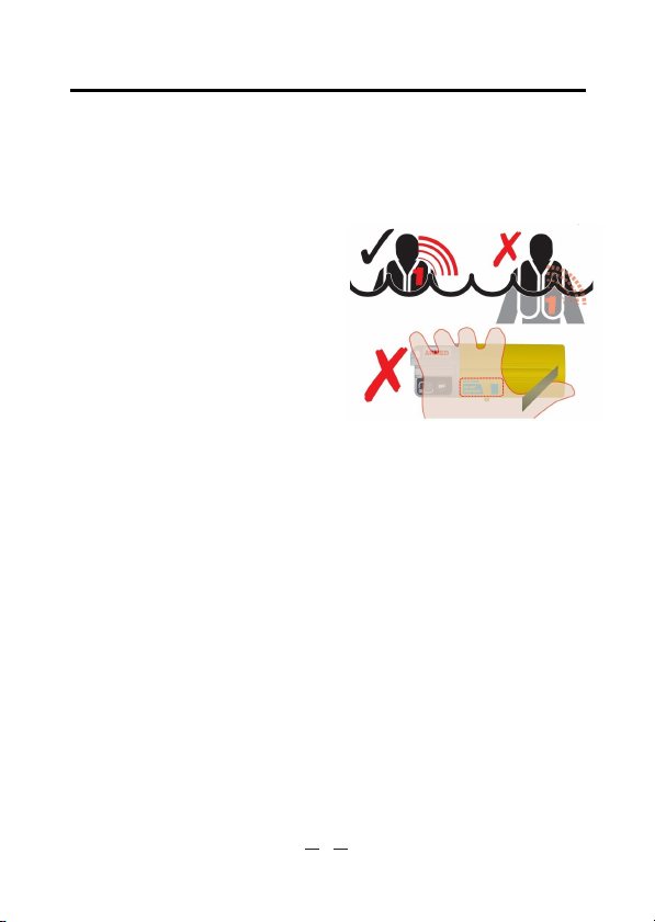
Ensure that the blue ar ea marked
GPS Zone is not obstructed or
“ ”
cove red in any way a nd always
has a clear view of t he sky.
Ens ure that the blue ar ea marked
GPS Zone is not o bstruct ed
“ ”
or covered in any way and alwa ys
has a clear vi ew of t he sky.
It is recommended th at the Short Test i s perform ed monthly. Return the
KS- 33R to a servi ce centre for battery replacement i f battery le vel is low.
Con firm tha t the battery expir y date show n is in date for the duration of
inte nded u se.
3
Page 6

Short Test
Quick system check and battery life test:
Press and hold OFF for 5 seconds then release 1 second, the LED light
" "
will twinkle 3 times indicated the battery is full, if twinkled twice, the battery
is remaining 75%, if twinkled once, the battery is remaining 50%, if the LED
lights do not twinkle, the battery is dead.
Long Test
Full system check including GPS activation and live test message transmission.
●
Requires a clear view of the sky.
Ensure GPS Zone on unit is not obstructed.
●
●
Perform away from busy sea areas where the
test transmission could confuse other AIS users.
Press and hold OFF for 10secs until 2sec long flash.
●
●
Unit will flash every 1sec until GPS fix is achieved.
●
After 1 minute a SART test message is sent, which
will be visible to all AIS systems within range.
●
At the end of the test, 3 long flashes indicates the
test is successful. No flashes indicates the test has
failed.
●
If the Long Test fails, check the GPS Zone has a
clear view of the sky and re-test. If the test fails a
second time, return the unit to the service centre.
4
Page 7

Caution
DO NOT ACTIVATE EXCEPT IN AN EMERGENCY
● This product is designed for use with an AIS receiver and is not a
substitute for a PLB or EPIRB.
This beacon is intended for use within the maritime environment where
●
permitted by national administrations. When activated, it transmits a
digital alert message to any vessel or shore station in radio range which
is equipped with a n AIS receiver.
Deliberate misuse of the device could result in a penalty.
Product and battery pack contain no user-serviceable parts. Do not
●
dismantle
Spring action antenna. Mount and deploy in such a way as to avoid
●
eye injury
●
Contains lithium batteries. Do not incinerate, puncture, deform,
short-circuit or recharge
Avoid cleaning the unit with chemical solvents as this may damage the
●
case material.
Radio Licensing. This product is a radio transmitter. Some administrations
●
may require that the user holds a valid radio license to c over its ownership and use.
●
This product emits low levels of radio frequency energy during operation.
Avoid handling the antenna once activated.
As AIS beacons are still very new, not all small-craft chart plotters with
●
AIS show the correct SART icon as recommended by the IMO. As a
minimum, they will show the same icon as used for other
craft - normally an arrow.
In addition, user settings generally allow you to configure the display to
show the MMSI number, which in AIS Beacons will always begin with
97. This will differentiate AIS Beacons (SARTs) from normal AIS targets.
If in doubt, check with your plotter manufacturer how they display SARTs
on screen.
STAR icon
5
Page 8

Transportation
Product contains small lithium metal batteries.
●
Passenger aircraft: Product can normally be carried on p assenger aircraft
●
in carry-on baggage as a personal item. It is recommended that you declare
the device to airline staff at check-in, in the same way you would a laptop
PC or video camera.
Air cargo: Not restricted as air cargo under IATA code UN3091 PI970.
●
–
Always check with carrier for additional restrictions.
End of Life Statement
At the end of its life, the product must be disposed of according to local
●
laws and regulations. Because the product contains a battery it must be
disposed of separately from household waste.
Do not incinerate, b ut take it to a recycling facility.
●
6
Page 9

INSTALLATION
Lifejacket Attachment
The KS-33R can be attached to the lifejacket using either the webbing clip or
oral tube attachment.
Fitting Oral Tube Clip
Can be f itted on l eft
or right side of unit
Activate
7
Page 10

SI ZE
50mm
23mm
65mm
29mm
24mm
25 .4m m
26m m
8
Page 11

28.7mm
28.7mm
22 mm
15mm25. 7mm
9
Page 12

GLOSSARY
ACA (AIS) Regiona l A ssi gnment Ch annel Ass ign ment
Mes sag e
ACK A cknowl edgemen t
ACS (AIS) Ch annel manageme nt i nformation so urc e
messag es
AFSK Aut o frequ enc y-sh ift keying
ALR (AIS) Al arm Messa ge
A to N Aid to Na vigatio n
AIS Automatic Identificatio n Syste m
BIIT B uilt In I nte gri ty Testin g
BNC Ba yon et fitting type There fore co nnector
COG Cou rse over Gro und
CR Car riage Return
CS C arrier Sense
CSTDMA Car rie r Se nse Time Division Multiple Ac ces s
DC Direct C urrent
DGNSS Differ ential Gl obal Naviga tio n Sa tellite System
DSC Di gital S ele ctive Ca lli ng
GLO NASS Global Navigation S ate llit e Sy stem
GNSS Global Naviga tio n Sa tellite Sys tem
GMSK Ga ussian Minimum Sh ift Keying
GPS Gl obal Po sitioni ng Satellite / System
HF H igh Frequ ency
IMO Int ern ational M aritim e Organi zation
IEC Intern ati onal Electro te chn ica l Co mmis sion
LED Light Emitting Diode
LF Line F eed
LNA Low- noi se Am plifier
MF Medi um F requency
MKD Mini mum Keypa d an d Di splay
10
Page 13

MMSI
Ma ritime M obi le S ervice ld entity
MPE Maximu m Pe rmi ssible E xpo sur e
NMEA National Ma rine El ect ronics Assoc iation
PC
Personal Com put er
PI Presentat ion Inter face
RF
Radio Frequency
RTCM Ra dio Tech nical C omm ission for Mariti me Servic es
Commis sio n
RX Receive or Receiver
RFI
SAR
Radio Frequency Inter ference
Specific Ab sor ption Rate
SELV Separ ate d Extra Lo w Voltage
SMS S hort Message Sy stem
SOG
Spe ed over Groun d
SRM Saf ety R elated Me ssage
TD MA Ti me- divisio n Mu ltiple A cces s
TN C Th read ed t ype RF con nec tor
TX Transmit or Tran smi tter
UTC Uni versal Time C o-o rdi nated
VDM
VDO
VHF
(AIS) V HF D ata Link M essages
(AI S) V HF data link own v essel messa ges
Very Hi gh Frequ enc y
VSWR Voltage Standing Wave Ratio
11
Page 14

 Loading...