

Onwa KR-15X8 Owner's Manual

TFT LCD COLOR MARINE RADAR
KR-12X8/15X8
OPERATOR'S MANUAL
KR-1238/1268
KR-1538/1568

SAFETY INSTRUCTIONS
"DANGER","WARNING" and "CAUTION" notices throughout this manual. It is
the responsibility of the operator and the installer of the equipment to read,
understand and follows these notices. If you have any questions regarding
these safety instructions, please contact a ONWA agent or dealer.
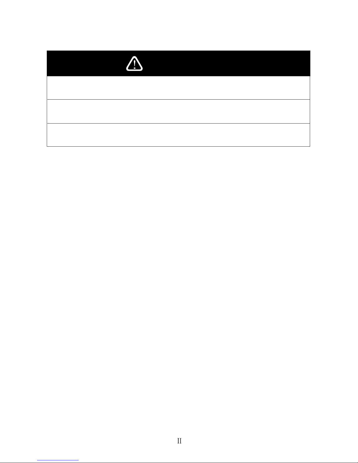
Do not open the equipment.
Hazardous voltage which can cause electrical shock, burn or serious
injury exists inside the equipment. Only qualified personnel should work
inside the equipment.
Wear a safety belt and hard hat when working on the antenna unit.
Serious injury or death can result if someone falls from the radar antenna
mast.
Stay away from transmitting antenna.
The radar antenna emits microwave radiation which can be harmful to
the human body, particularly the eyes. Never look directly into the
antenna radiator from a distance of less than 1 m when the radar is in
operation.
Turn off the radar power switch before servicing the antenna unit.
Post a warning sign near the switch indicating it should not be
turned on while the antenna unit is being serviced.
Prevent the potential risk of someone begin struck by the rotating
antenna and exposure to the RF radiation hazard.
Do not disassemble or modify the equipment.
Fire electrical shock or serious injury can result.
Turn off the power immediately if water leaks into the equipment or the
equipment is emitting smoke or fire.
Continued use of the equipment can cause fire or electrical shock.
Do not place liquid-filled containers on the top of the equipment.
Fire or electrical shock can result if a liquid spills into the equipment.
WARNING
CAUTION
Use the proper fuse.
Use of a wrong fuse can result in fire or permanent equipment damage.
Do not use the equipment for other than its intended purpose.
Personal injury can result if the equipment is used as a chair or stepping stool, for example.
Do not objects on the top of the equipment.
The equipment can overheat or personal injury can result if the object falls.

1. PRINCIPLE OF OPERATION 7
2. BASIC OPERATION 9
1.1 What is Radar? 7
1.2 How Ships Determined Position Before Radar 7
1.3 How Radar Determines Range 7
1.4 How Radar Determines Bearing 7
1.5 Radar Wave Speed and Antenna Rotation Speed 7
1.6 The Radar Display 8
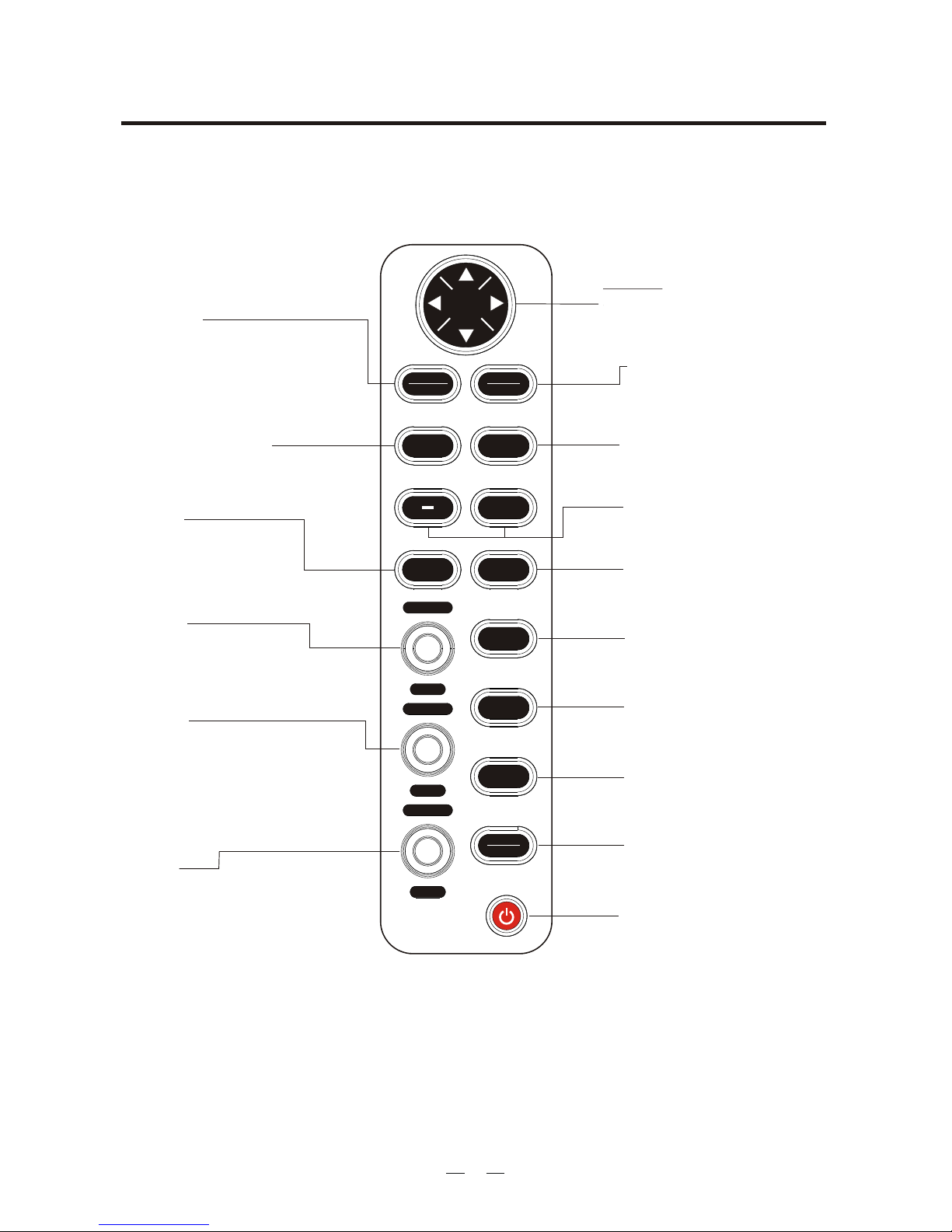
2.1 Control Description 9
2.2 Display Indication and Markes 10
2.3 Turning the Radar On and Off 11
2.4 Transmitting 11
2.8 Stand-by 13
2.9 Selecting the Range 14
2.10 Adjusting Picture Brilliance 14
2.12 Adjusting Receiver Sensitivity 15
FOREWORD 1
KR-1238/1538 SPECIFICATION 2
KR-1268/1568 SPECIFICATION 4
CONFIGERATION OF KR-1238/1268/1538/1568 6
2.11 Setup display color 15
TABLE OF CONTENTS
2.5 Echo area 11
2.6 11Reference Position
2.7 Own Ship Marker 13
2.13 Adjusting the A/C SEA Control (reducing sea clutter) 16

2.19 Shifting (off centering) the Pcture 23
2.20 Zoom 23
3.1 Basic Menu Operation 25
3.2 Selecting the Presentation Mode 26
3.3 Magnifying Long Range Echoes (echo stretch) 26
3.4 Echo Trail 27
3.5 Suppressing Radar Interference 28
3.6 Selecting Pulse 29 Length
3.7 Guard Alarm 30
3.8 Watchman 32
3.9 Display Navigation Data 33
4.1 Multiple Echoes 37
4.2 Side-lobe Echoes 37
4.3 Indirect Echoes 38
4.4 Blind and Shadow Sectors 39
3. MENU OPERATION 25
4. FALSE ECHOES 37
3.10 34FUNCTION MENU Description
3.11 VIDEO MENU Description
3.12 35Function Keys
3.13 36Suppressing Nois
35
2.18 Using the Offset EBL 21
2.17 Measuring the Bearing 20
2.14 Apply the A/C RAIN (reducing rain clutter) 17
2.15 Erasing the Heading Line 18
2.16 Measuring the Range 18
2.21 Outputting Target Position 24
3.14 Adjusting Brilliance of Markers 36

6.3 Exchange of Fuse for 24/32V Power Supply 55
6.4 Checking the Installation 55
6.5 Adjustments 55
5.1 Preventative Maintenance 41
5.2 Replacing the Fuse 41
5.3 Troubleshooting 41
5.5 Life Expectancy of Magnetron 43
6.1 Antenna Unit Installation Sitting handling considerations 44
6.2 Display Unit Installation Mounting considerations 52
5. MAINTENANCE & TROUBLESHOOTING 40
6. INSTALLATION 44
5.4 Self Test 41
7. ARPA 61
9. DISPLAY UNIT SIZE 79
8. AIS 71
10. ABBREVIATIONS 83

Thank you for your choice of ONWA MODEL KR-12X8/15X8 Marine Radar.
The radar is designed and constructed to meet the rigorous demands of the marine
environment. However, no machine can perform its intended function unless
properfly installed and maintained. Please carefully read and follow the
recommended procedures for installation, operation and maintenance. While this
unit can be installed by the purchaser, any purchaser who has doubts about his or
her technical abilities may wish to have the unit installed by a ONWA
representative or other qualified techician. The importance of a through installation
can not be overemphasized. We would appreciate hearing form you, the end user,
about whether user, about user, about whether we are achieving our purposes.
Your radar has a large variety of functions, all contained in a remarkably small
cabinet.
The main features of the MODEL KR-12X8/15X8 are.
Traditional ONWA reliability and quality in a compact, lightweight and low-cost
radar.
Durable brushless antenna motor.
On-screen alphanumeric readout of all operational information.
Standard features include EBL (Electronic Bearing Line), VRM (Variable Range
Marker), Guard Alarm, Display Off Center, and Echo Trail.
Watchman feature periodically transmits the radar to check for radar targets
which may be entering the alarm zone.
Ship s position in latitude and longitude and range and bearing to waypoint,
and ship's speed/ heading/course can be shown in the right hand side text area.
(Requires a navigation aid which can output such data in IEC61162 format.)
Zoom feature provided.
'
Features
FOREWORD
1
Thank you for considering and purchasing ONWA equipment.

KR-1238/1538 SPECIFICATION
ANTENNA UNIT
1. Radiator Slotted waveguide array
2. Radiator length 55 cm
3. Horizontal beamwidth 4
4. Vertical beamwidth 25
5. Sidelobe
Within 20 off mainlobe; less than -18 dB
Outside 20 off mainlobe; less than -23 dB
6. Polarization Horizontal
7. Antenna rotation speed 24 rpm ( 2)
8. Wind resistance Relative wind speed 100 knots (51.5 m/s)
:
:
:
:
:
:
:
:
TRANSCEIVER MODULE (contained in radome)
1. Transmitting tube MSF1421B or MAF1421B
2. Frequency 9410 MHz 30MHz
3. Peak output power 4kW nominal
4. Pulselength & pulse repetition rate
0.08 S, 2100 Hz (0.125, 0.25, 0.5, 0.75, 1.5nm)
0.3
:
:
:
:
S, 1200 Hz (1.5, 2, 3nm)
0.8 S, 600 Hz (3, 4, 6, 8, 12, 16, 24, 36nm)
5. Warm up time: 1:30 minutes
6. Modulator: FET switching method
7. I.F.: 60MHz
8. Tuning: Automatic or manual
9. Receiver front end: MIC (Microwave IC)
10. Bandwidth:
Tx pulselength 0.3 S and 0.08 S: 25MHz
Tx pulselength 0.8 S: 3MHz
11. Duplexer: Circulator with diode limiter
2

DISPLAY UNIT
1. Indication system LCD digital display
2. Display 12 or 15 LED backlight, 32-bit TFT Color LCD Display
3. Range scale (nm)
Range, Range interval and no. of Rings:
0.125(0.0625,2), 0.25(0.125,2), 0.75(0.25,3), 1(0.25,4), 1.5(0.25,6),
2(0.5,4), 3(0.5,6), 4(1,4), 6(1,6), 8(2,4), 12(2,6), 16(4,4), 24(4,6), 36(6,6)
4. Bearing resolution 4
5. Bearing accuracy Within 1
6. Range discrimination Better than 30 m
7. Range ring accuracy 0.9% or range in use or 8 m, whichever is larger
8. Minimum range Better than 25 m
9. Markers
Heading line, Bearing scale, Range ring, VRM, EBL Tuning indicator,
Cursor, Alarm zone, North mark (heading sensor input required)
10. Alphanumeric indication
Range, Range ring interval, Pulselength, Interference rejection (IR), VRM,
EBL, Stand-by (ST-BY), Radar alarm, Echo stretch (ES), Range to cursor,
Bearing to cursor, Echo trailing (TRAIL), Trail time, Trail elapsed time,
Navigation data (navigation input required), heading (HDG, heading sensor
input required)
11. Vibration
Vibration Total amplitude
1 to 12.5 Hz 1.6mm
12.5 to 25 Hz 0.38mm
25 to 30 Hz 0.10mm
12. Temperature
Antenna unit; -25 to + 70
Display unit; -10 to + 50
13. Humidity
Relative humidity 93% or less at + 40
14. Power supply & power consumption : 12V, 24V or 32VDC (10.5V to 40
VDC) 60W
15. Compass safe distance
:
:
:
0.5(0.125,4),
:
:
:
:
:
:
:
:
:
:
:
:
Standard Compass
Display unit 0.75m 0.6m
1.75m3.1mAntenna unit
Steering Compass
3

KR-1268/1568 SPECIFICATION
ANTENNA UNIT
1. Radiator: Slotted waveguide array
2. Radiator length 120 cm
3. Horizontal beamwidth 1.9
4. Vertical beamwidth 22
5. Sidelobe
Within 20 off mainlobe; less than -24 dB
Outside 20 off mainlobe; less than -30 dB
6. Polarization Horizontal
7. Antenna rotation speed 24 rpm
8. Wind resistance Relative wind speed 100 knots(51.5 m/s)
:
:
:
:
:
:
:
TRANSCEIVER MODULE (contained in antenna)
1. Transmitting tube MAF1421 or MSF1421
2. Peak output power 6KW nominal
3. Pulselength & pulse repetition rate
0.08 S, 2100 Hz (0.125, 0.25, 0.5, 0.75, 1.5nm)
0.3
:
:
:
S, 1200 Hz (1.5, 2, 3nm)
0.8 S, 600 Hz (3, 4, 6, 8, 12, 16, 24, 36, 48, 64nm)
4. Bandwidth:
Tx pulselength 0.3 S and 0.08 S: 25MHz
Tx pulselength 0.8 S: MHz
5. Other: See KR-1238/1538
4
DISPLAY UNIT
1. Range scale (nm):
Range, Range interval and no. of Rings:
, 48(8,6),
64(16,4)
2. Compass safe distance:
0.125(0.0625,2), 0.25(0.125,2), 0.75(0.25,3), 1(0.25,4), 1.5(0.25,6), 2(0.5,4),
3(0.5,6), 4(1,4), 6(1,6), 8(2,4), 12(2,6), 16(4,4), 24(4,6), 36(6,6)
Standard Compass
Display unit 0.75m 0.6m
0.91m1.3mAntenna unit
Steering Compass
3. Power supply & power consumption: 12V, 24V or 32VDC (10.5V to 40VDC)
60W.

INTERFACE (NMEA0183)IEC61162
Input data sentences:
Own ship`s position: GGA>RMA>RMC>GLL
Speed: RMA>RMC>VIG>VHW
Heading (True): HDT>HDG*>HDT*>VHW>VHW*
Course (True): RMA>RMC>VTG
Course (Magnetic):
VTG>RMA*>RMC
Waypoint (Range, Bearing): RMB>BWC>BWR
Loran time difference: RMA>GLC>GTD
Water depth: DPT>DBT
Water temperature: MDA>MTW
XTE: RMB>XTE>APB
*: Calculated value based Magnetic variation.
AIS: VDO>VDM>ACA>ACS>ALR>ACK
Output data sentences:
5
TLB>TLL>TTD>TTM
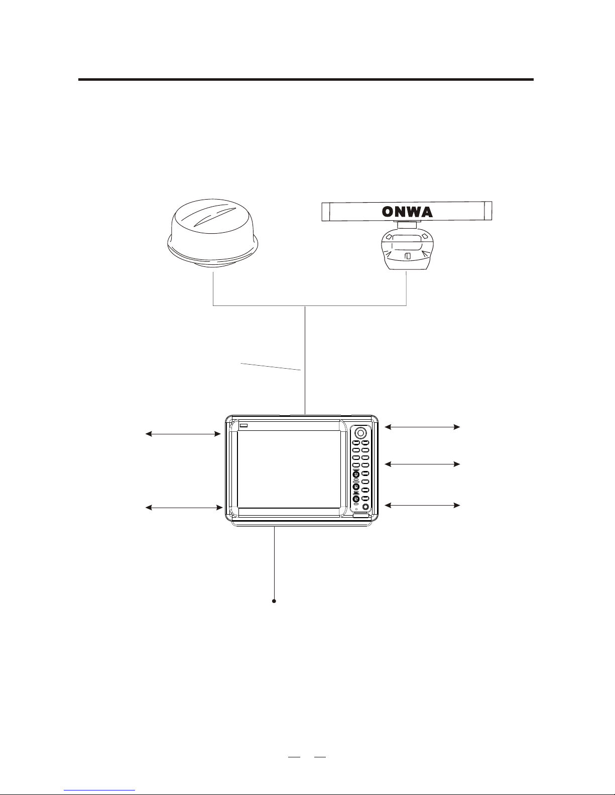
CONFIGERATION OF KR-1238/1268/1538/1568
ANTENNA UNIT
Antenna cable
KRC-003-15/20/30
15/20/30m
NMEA-1
5 Pin
6 Pin
3M
10.5 to 40VDC
KR-1238/1538
KR-1268/1568
Display UNIT
NMEA-2
UPGRADE
4 Pin
VGA
7 Pin
RS422
8 Pin
6

1. PRINCIPLE OF OPERATION
The term "RADAR" is an acronym meaning "RAdio Detection And Ranging".
Although the basic principles of radar were developed during World War II,
Before the invention of radar, when running in fog near a rugged shoreline,
ships would sound a short blast on their whistles, fire a shot, or strike a bell.
The time between the origination of the sound and the returning of the echo
indicated how far the ship was from the cliffs or the shore. The direction from
The bearing to a target found by the radar is determined by the direction in
which the radar scanner antenna is pointing when it emits an electronic pulse
and then eceives a returning echo. Each time the scanner rotates pulses are
transmitted in the full 360 degree circle, each pulse at a slightly differentbearing
from the previous one. Therefore, if one knows the direction in whichthe signal
Note that the speed of the radar waves out to the target and back again as echoes
is extremely fast compared to the speed of totation of the antenna. By the time
radar echoes have returned to the scanner, the amount of scanner rotation after
Radar determines the distance to the target by calculating the time difference
between the transmission of a radar signal and the reception of the reflected
echo. It is a known fact that radar waves travel at a nearly constant speed of
162,000 nautical miles per second. Therefore the time required for a transmitted
signal to travel to the target and return as an echo to the source is a measure
of the distance to the target. Note that the echo makes a complete round trip,
but only half the time of travel is needed to determine the one-way distance to
the target. This radar automatically takes this into account it making the range
echoes as an aid to navigation is not a new development.
which the echo was heard indicated the relative bearing of the shore.
is sent out, one knows the direction from which the echo must return.
initial transmitting of the radar pulse is extremely small.
calculation.
1.1 What is Radar?
1.2 How Ships Determined Position Before Radar
1.4 How Radar Determines Bearing
1.5 Radar Wave Speed and Antenna Rotation Speed
1.3 How Radar Determines Range
7
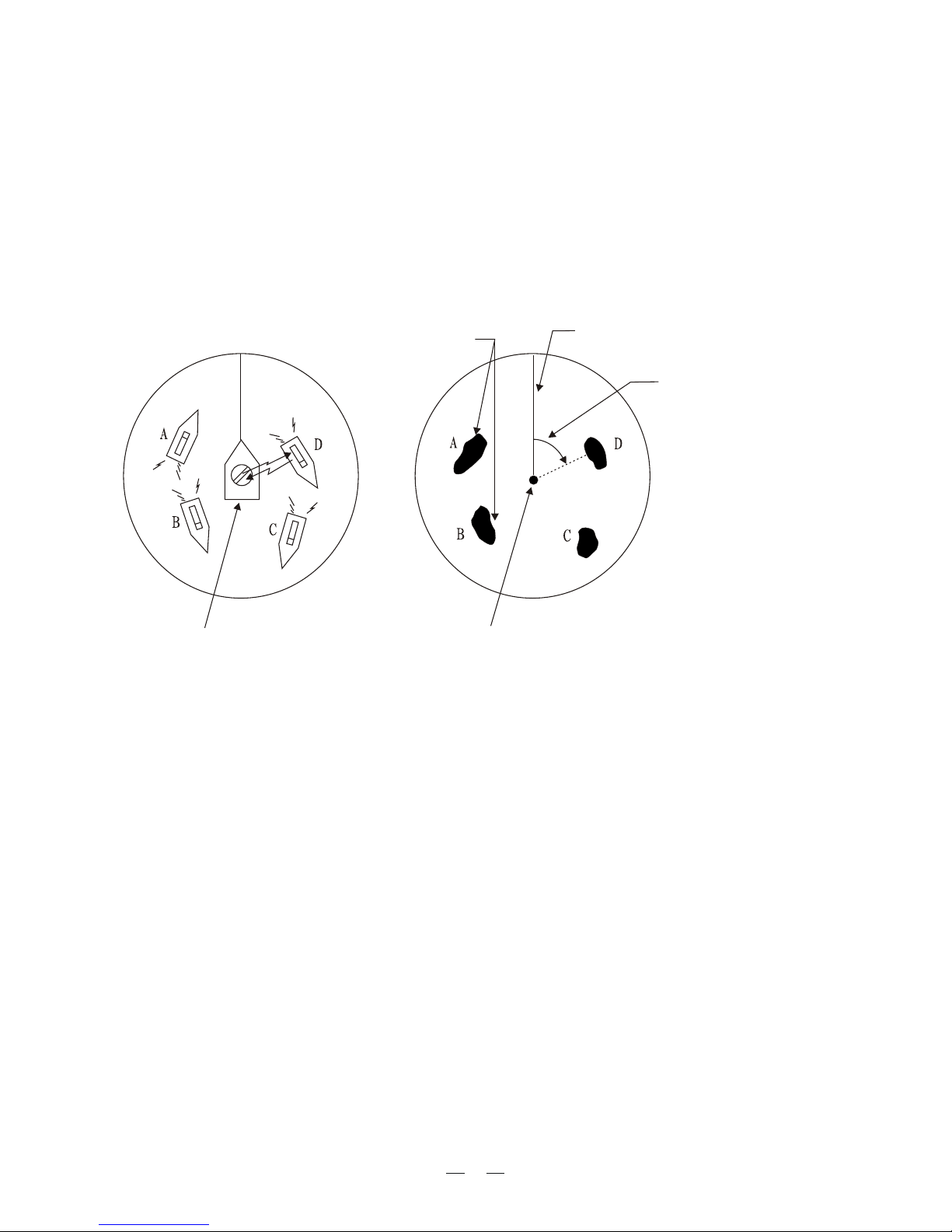
The range and bearing of a target is displayed on what is called a Plan Position
Indicator (PPI). This display is essentially a polar diagram, with the transmitting
ship's position at the center. Images of target echoes are received and displayed
at their relative bearings, and at their distance from the PPI center. With a
continuous display of the images of targets, the motion of the transmitting ship
1.6 The Radar Display
Own ship
(radar)
(A) Bird's eye view of situation
(B) Radar picture of (A)
Own ship
in center
Targets
Heading line
Range and bearing of
a target, relative to own
ship, are readable on
the PPI
Figure 1-1 How radar works
is also displayed.
8
2. BASIC OPERATION
2.1 Control Description
Figure 2-1 Control panel
*Default switch function.
Brief press:
Displays the data of target
selected with the cursor
Long press:
Terminates plotting of the target
selected with the cursor.
Opens/closes menus
Selects:
EBL1/EBL2/VRM1/VRM2
Control:
Adjusts sensitivity.
Switch:
Temporarily erases heading
line (and north mark if displayed).
Control:
Reduces sea clutter.
Switch*:
(Long press) Shifts your vessel`s
position to cursor location.
(Brief press) Doubles size of
area between your vessel and
location selected by cursor.
Omnipad
Shifts cursor, VRM and EBL;
select items and options on
menu.
(1) Acquires the target selected
with the ominipad.
(2) Registers selection on
menus.
Sets guard zone area.
Sets radar range.
Enables/erases
EBL1/EBL2/EBL3/EBL4.
Outputs target position data.
Automatically reduces sea and
rain clutters.
Adjusts display brilliance.
Sets radar in stand-by;
transmits radar pulse.
Turns power on/off.
Control:
Reduces rain clutter.
Switch*:
Displaces the EBL origin.
SELECT
CANCEL
ACQ
ENTER
MENU
GUARD
+
EBL/VRM
SELECT
EBL/VRM
CONTROL
TLL
A/C AU
TO
ST BY
TX
BRILL
GAIN
A/C SEA
HM-OFF
F1
A/
C RAIN
F2
9
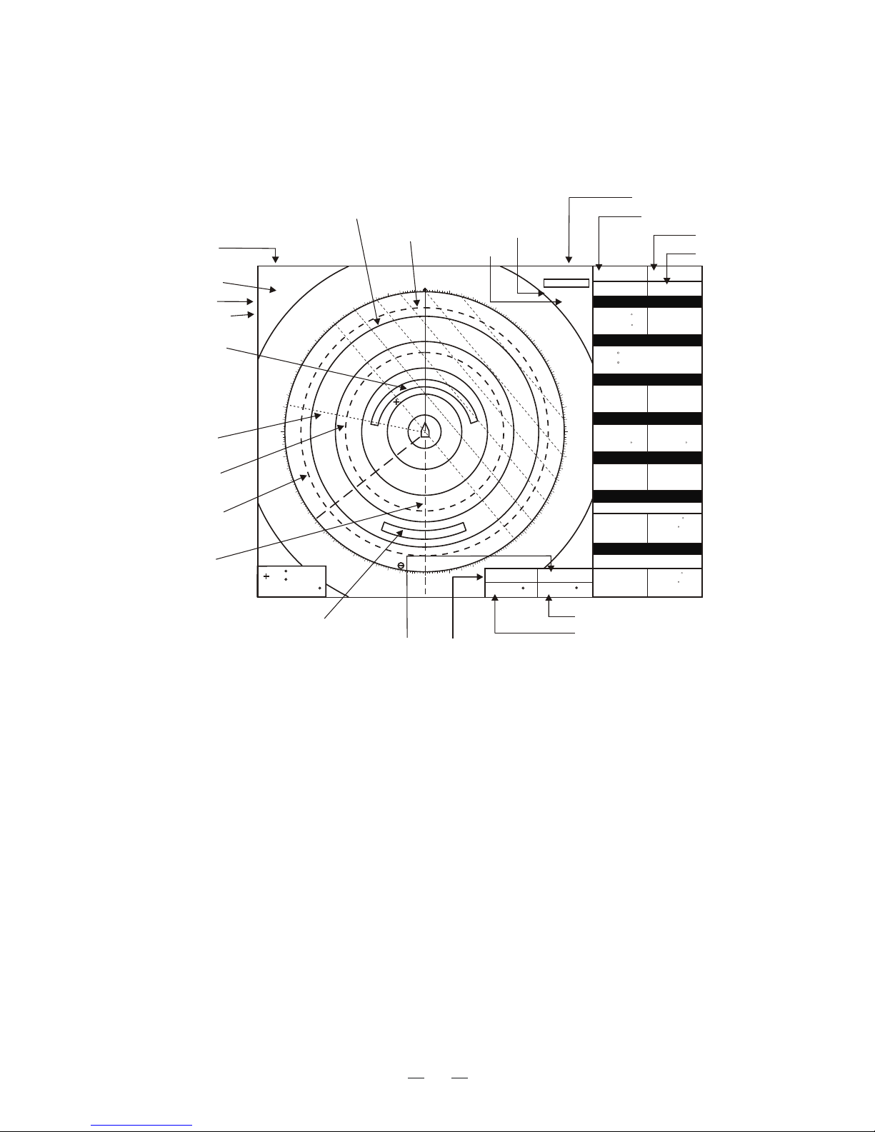
2.2 Display Indication and Markers
Figure 2-2 Display indications
Range ring interval
Interference rejector
Off center
Tuning indicator
AUTO
OFF-CENT
ZOOM
36
NM
6
LP
HU
IR
OFF
TRAIL
OFF
ES
A/C Auto
OFF
OFF
HDG 270
COG 255 T
X-band
SOG 03.5KT
22
45.135 N
21.237 E
115
TTG
**.**
Off
1.02~2.10NM
IN (or OUT)
VRM1 25.0 NM
EBL1 138 K
VRM1 10.9 NM
EBL2 152 K
RANGE:
BEARING:
VESSEL A
Safe
SOG 15.0KT
RNG 130.0NM
OWN SHIP
WAYPOINT
MARKERS
CURSOR R/B
ARP VESSEL
AIS VESSEL
GUARD ZONE 1
CPA 10.1NM
COG 270 M
BRG 99
M
TCPA 10:20:30
TCPA 24:30:30
BRG 99
M
CPA 9.1NM
RNG 20.0NM
SPD 12.0KT
CRS 128M
VESSEL 1
Safe
000
030
060
090
120
150
330
300
270
240
210
30.0V
22 45.135 N
21.237 E
115
99.9NM 360
Pulselength
Display mode
Range
Zoom
Echo Stretch
A/C Auto
VRM1 VRM2
EBL1 EBL2
281 K
180 K
15.8NM
31.8NM
VRM1 range
VRM2 range
EBL1 range
EBL2 range
GUARD ZONE 2
EBL2
VRM2
VRM1
EBL1
GUARD ZONE 1
RANGE RING
PI LINE
10
GUARD ZONE 2
After the power is turned on and the magnetron has warmed up, STAND-BY
appears at the screen center. This means the radar is now fully operational. In
stand-by the radar is available for use at anytime - but no radar waves are being
transmitted. Press the [ST-BY/TX] key to transmit. When transmitting, any echoes
from targets appear on the display. This radar displays echoes in eight tones of
2.4 Transmitting
green according to echo strength.
2.3 Turning the Radar On/Off
Press the [POWER] key to turn the radar on or off.
The control panel lights and a timer displays the time remaining for warm up of
the magnetron (the device which produces radar pulses), counting down from 1:30
to 0:01.
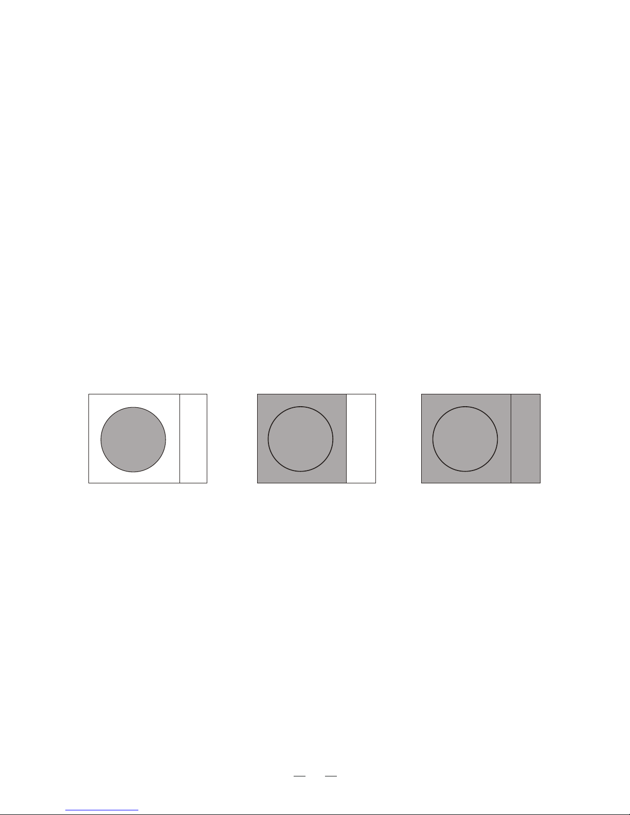
2.5 Echo area
The echo display area for the B, C and W types is available in three configurations:
round, wide, and full screen. You can select a configuration with 7 ECHO AREA
on the ECHO menu.
Round Wide Full
2.6 Reference Position
11
The reference position for measurements (range, bearing, etc.) and markers (heading
line, stern mark, etc.) can be antenna position or consistent common reference point
(CCRP), which is a location on own ship to which all horizontal measurements, for
example range, bearing, relative course, relative speed, closest point of approach
To select reference position, press the [MENU] key to enter the Main Menu, select
Reference Point and press [ACQ/ENTER] key, in the pop-up window select
The position of the own ship marker changes according to reference position as
shown below. If the CCRP is positioned outside of the effective display area, the
""
(CPA) or time to closest point of approach (TCPA), are normally referenced.
""" "ANT or CCRP and press [ACQ/ENTER] key.
bearing scale is indicated with the appropriate reduced detail.
Radar antenna
position is at
center of display
Conning position is at
center of display
ANT position CCRP position
Range and bearing are measured and graphics are drawn according to reference
position as in the table below.
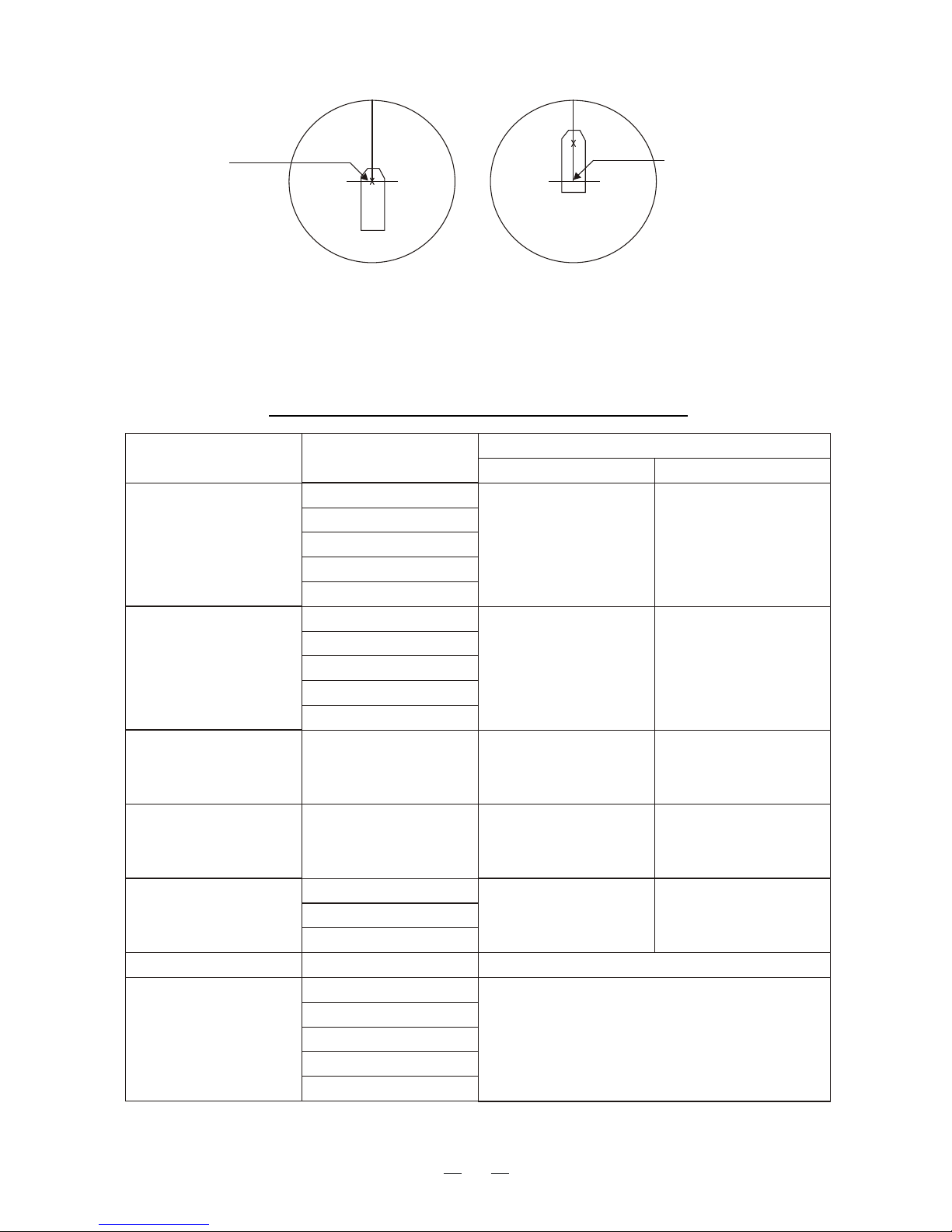
Marks, measurements and reference point
Category Item
Reference point
CCRP Antenna position
Range and bearing
measurement
EBL
VRM
Cursor
PI line
Range ring
Range and bearing
measured from CCRP
Range and bearing
measured from antenna
position
Heading line
Stern mark
Beam line
Own ship vector
Own ship track
Drawn from CCRP
Drawn from antenna
position
Graphics
Bearing cursor
Drawn with CCRP at
center
Drawn with antenna
position at center
Course, speed
Calculated with CCRP
at center
Calculated with antenna
position at center
CPA,TCPA
Calculated with CCRP
at center
Calculated with antenna
position at center
BCR, BCT
Calculated from bow position
Own ship data
Heading
Speed
Course over ground
Speed over ground
Own L/L
Data from sensor, regardless of reference
point selected
12
2.7 Own Ship Marker
Own ship marker ( ) may be inscribed on the screen as below.
1. Go to Installation setup menu;
2. Select the Own Ship Shape and press [ACQ/ENTER] key;
3. Select the Draw and press [ACQ/ENTER] key;
4. Drawing interface pops up on the screen as follows:
""
""
""
10
01
02
03
04
05
06
07
08
09
When you won't be using the radar for an extended period, but you want to keep
it in a state of readiness, place it in stand-by by pressing the [ST-BY/TX] key.
The display shows "STAND-BY," navigtion data, or goes into the economy
mode depending on menu setting. (More on menu operation later.)
2.8 Stand-by
can be set to automatically turn itself off when in stand-by,
to reduce power consumption. This feature is called the "economy mode."
Power consumption in the economy mode is 28W. When economy mode is no,
If a navigation aid inputs navigation data to this radar, navigation data can be
displayed during stand-by. You can turn the navigation data display on/off
through the menu. Figure 2-3 shows a typical navigation data display during
standby. Similarly, if the AIS data input case , AIS data can be display during
Note 1:Availability of a particular display item depends on incoming data.
Note 2:When Range to Waypoint reaches 0.1nm, the WPT mark jumps to dead
ahead even though a difference may exist between heading and BRG to WPT.
Note 3:When cross track error exceeds 1 nm on either side, the XTE mark
The LCD display
13
he lamp next to the [POWER] key lights.
Stand-by.
starts blinking.
Economy mode
Navigation data display during stand-byor AIS data
Figure 2-3 Typical navigation data display
during stand-by
E
Speed
Depth
To Waypoint
bearing heading
Heading
Time-to-go to
TO Waypoint
Bearing TO Waypoint
Range to TO Waypoint
SPEED
DEPTH
TRIP
TEMPERATURE
10.5
125
Kt
m
ST-BY
000.3nm
+17.3
Time-to-go to Stand-by
Trip distance since power on
Course
S
Ship s position in
latitude and longitude
'
Cross Track Error
Mark
" " shows
direction and amount
of error.
L XTE
XTE R
XTE
R 0.3NM
W
N
1.0 1.0
0.5 0.5
HDG
092.5
CRS
180.0 M
WPT
TTG
01:08
BRG 45.0 M
RNG 12.0NM
OWN SHIP
LAT 30 00 . 00N
LON 135 00.00E
The range selected automatically determines the range ring interval, the number
of range rings, pulselength and pulse repetition rate, for optimal detection
capability in short to long ranges. You can select which ranges and pulselength
(for 1 mile range) to use through the menu. The range, range ring interval and
pulselength appear at the botton left-hand corner of the display.
When navigating in or around crowded harbors, select a short range to watch for
possi ble collision situations.
If you select a lower range while on open water, increase the range occasionally
to watch for vessels that may be heading your way.
2.9 Selecting the Range
To select a range;
2.10 Adjusting Picture Brilliance
The [BRILL] key adjusts the brilliance of the radar picture in eight levels.
Press the [BRILL] key to set the brilliance level.
The current level momentarily appears on the screen.
14
In order to adapt to the different environments, the radar echo display the background color and echo color can be set by users themselves, there are five kinds
of background colors and three kinds of echo colors available. Setting methods are
2.11 Setup display color
as follows:
1.By menu
1) Press [FUNCTION] key open main menu;
2) Select ''OTHER MENU'' and press [ACQ/ENTER] key;
3) Press [ ]or [ ] key select ''Color setting'' & press [ACQ/ENTER] key
open the color setup menu;
4) Press [ ] or [ ] key select ''Background Color'' or ''Echo Color'' press
[ACQ/ENTER] key;
5) Press [ ] or [ ] select color desired and press [ACQ/ENTER] key;
6) Press [MENU] key to close the menu.
2.Using the function key
The function keys [F1] function default setting for ''Background Color'' ,[F2]
key default setting for ''Echo Color''. Directly on the keyboard you can press
these two keys select the desired color setting.
The [GAIN] control adjusts the sensitivity of the receiver. It works in precisely
the same manner as the volume control of a broadcast receiver, amplifying the
signals received. The proper setting is such that the background noise is just
visible on the screen. If you set up for too little sensitivity, weak echoes may
be missed. On the other hand excessive sensitivity yields too much background
noise; strong targets may be missed because of the poor contrast between desired
echoes and the background noise on the display. To adjust receiver sensitivity,
transmit on long range, and adjust the [GAIN] control so background noise is
2.12 Adjusting Receiver Sensitivity
just visible on the screen.
15
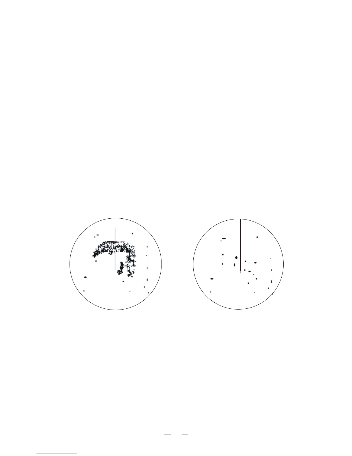
Echoes from waves can be troublesome, covering the central part of the display
with random signals known as "sea clutter." The higher the waves, and the higher
the scanner above the water, the further the clutter will extend. Sea clutter appears
on the display as many small echoes which might affect radar performance. (See
the Figure 2-4.) When sea clutter masks the picture, adjust the A/C SEA control to
The [A/C SEA] control reduces the amplification of echoes at short ranges (where
clutter is the greatest) and progressively increases amplification will be normal at
2.13 Adjusting the A/C SEA Control (reducing sea clutter)
How the A/C SEA control works
reduce the clutter.
those ranges where there is no sea clutter.
Adjusting the A/C SEA control
The proper setting of the A/C SEA should be such that the clutter is broken
up into small dots, and small targets become distinguishable. If the control is set
Too low, targets will be hidden in the clutter, while if it is set too high, both sea
clutter and targets will disappear from the display. In most cases adjust the control until clutter has disappeared to leeward, but a little is still visible windward.
1. Confirm that the sensitivity is properly adjusted, and then transmit on short
range.
2. Adjust the [A/C SEA] control so small targets are distinguishable but some
clutter remains on the display.
Figure 2-4 How to adjust the STC control
A/C SEA control adjusted;
sea clutter suppressed.
Sea clutter at
display center
16
Tip for adjusting the A/C SEA
A common mistake is to over-adjust the circuit so all the clutter is removed. As
an example set up for maximum STC. You will see how the center of the display
becomes dark. This dark zone can be dangerous (targets may be missed),
especially if the sensitivity is not properly adjusted. Always leave a little clutter
visible on the display to be sure weak echoes will not be suppressed. If there is
no clutter visible on the display, turn off the circuit.
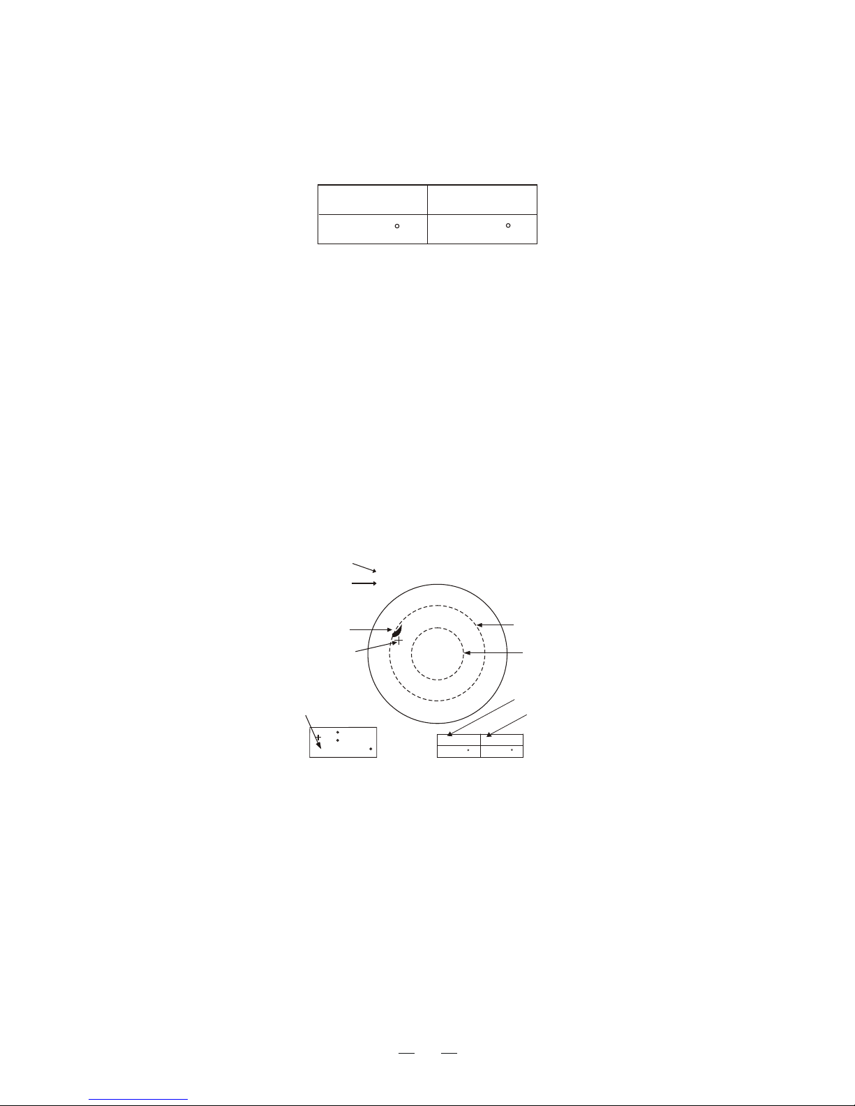
2.14 Apply the A/C RAIN (reducing rain clutter)
The vertical beamwidth of the antenna is designed to see surface targets even
when the ship is rolling. However, by this design the unit will also detect rain
clutter (rain, snow, hail, etc.) in the same manner as normal targets. Figure 2-5
Appearance of rain clutter
A/C RAIN control adjusted;
rain clutter suppressed.
Figure 2-5 Effect of A/C RAIN
Adjusting A/C RAIN
When rain clutter masks echoes, adjust the [A/C RAIN] Control, This control splits up these unwanted echoes into a speckled pattem, making recognition of solid
targets easier.
Shows the appearance of rain clutter on the Display.
Note: In addition to reducing clutter, the [A/C RAIN] control can be used in fine
weather to clarify the picture when navigating in confined waters. However, with
the circuit activated the receiver is less sensitive. Therefore, turn off the circuit
17
when its function is not used.

2.15 Erasing the Heading Line
The heading line may occasionally mask a target. To view the target, you can
temporarily erase the heading line by pressing and holding down the [GAIN (HM
OFF)] control. Release the control to re-display the marks.
Automatic adjustments of A/C SEA and A/C RAIN
Push the [A/C Auto] key. "A/C Auto" at the bottom left-hand corner of
the display when the A/C AUTO circuit is on. You can fine tune by adjusting the
[A/C SEA], [A/C RAIN] and [GAIN] controls.
appears
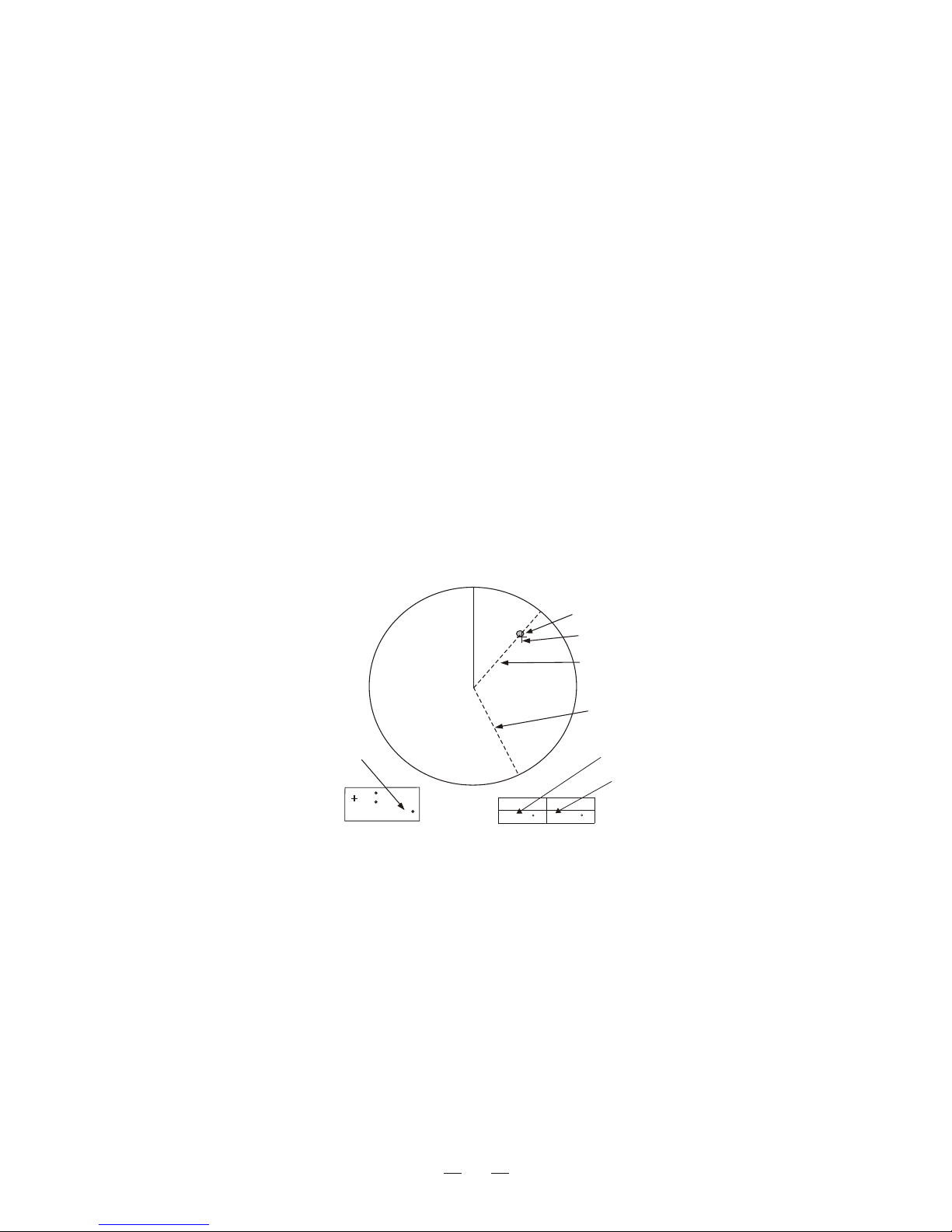
2.16 Measuring the Range
By range ring
By cursor
You can measure the range to a target three ways: by the range rings, by the
cursor, and by the VRM (Variable Range Marker).
Count the number of rings between the center of the display and the target.
Check the range ring interval and judge the distance of the echo from the echo
Operate the omnipad to place the cursor intersection on the inside edge of the
target echo, The range to the target, as well as the bearing, appears at the
bottom right-hand corner of the display.
from the inner edge of the nearest ring.
Heading
Line
Figure 2-6 Heading line
18
2. Press the [EBL/VRM CONTROL] key enable control of the VRM by the
omnipad.
3. Operate the omnipad to place the outside edge of the VRM on the inside
edge of the target.
4. Check the VRM readout at the bottom right-hand corner of the display to
find the range to the target.
5. To anchor the VRM, press the [EBL/VRM CONTROL] key.
6. To erase the VRM, press and hold down the [EBL/VRM CONTROL] key
about two seconds.
By VRM
1. Press the [EBL/VRM SELECT] key to circumscribe a VRM readout (at the
bottom center).Each press of the key selects the readout of EBL1,EBL2,VRM1
or VRM2 in that order.
Figure 2-7 Display bottom, showing location
of EBL and VRM readouts
Note: You can display the range readout of the VRM and cursor in nautical
miles, statute miles or kilometers. For details see the next chapter
Target
Cursor
VRM1
VRM2
Range
Range ring
Interval
6.0 NM
2.0
VRM1 Range
VRM2 Range
Figure 2-8 Measuring range by the cursor,
range rings and VRM
VRM1 VRM2
EBL1 EBL2
138 R
152 R
25.0NM
10.9NM
VRM1 VRM2
EBL1 EBL2
138 R
152 R
4NM
2NM
Cursor range
22 45.135 N
21.237 E
115
3.5NM 300
19
2.17 Measuring the Bearing
By EBL
By cursor
There are two ways to measure the bearing to a target: by the cursor, and by
the EBL (Electronic Bearing Line).
1. Press the [ERL/VRM] key to an EBL readout (at the bottom
left-hand corner). Each press of the key selects the readout of EBL1, EBL2,
display
VRM1 or VRM2 in that order.
2. Press the [EBL/VRM CONTROL] key to enable control of the omnipad.
3. Operate the omnipad to bisect the target with the EBL.
4. Check the EBL readout at the bottom left-hand corner of the display to find
the bearing to the target.
5. To anchor the EBL, press the [EBL/VRM CONTROL] key.
6. To erase the EBL and its readout; press and hold down the [EBL/VRM
CONTROL] key about two seconds.
Operate the omnipad to bisect the target with the cursor intersection. The bearing
to the target appears at the bottom of the display.
Note: The bearing readout for the EBL and the cursor can be display in relative
or true bearing (true bearing requires heading sensor input) For north up and
course up display modes the bearing reference is always true. For details see
Target
Cursor
EBL1
EBL2
Cursor Bearing
Figure 2-9 How to measure bearing by EBL and cursor
EBL1 Bearing
EBL2 Bearing
22 45.135 N
21.237 E
115
3.5NM 45
VRM1 VRM2
EBL1 EBL2
40 R
160 R
4NM
2NM
20
the next chapter.
Tips for measuring bearing
Bearing measurements of smaller targets are more accurate; the center of
Bearings of stationary or slower moving targets are more accurate than
To minimize bearing errors keep echoes in the outer half of the picture by
changing the range scale; angular difference becomes difficult to resolve as
larger target pips is not as easily identified.
Bearings of faster moving targets.
a target approaches the center of the display.
2.18 Using the Offset EBL
The offset EBL provides two functions: predict collision course of radar target and
measure the range and the bearing between two targets.
Predicting collision course
1. Press the omnipad to place the cursor on the center of the target.
2. Press the [EBL/VRM SELECT] key to choose EBL1 readout and then press
the [EBL/VRM CONTROL] key.
3. Select on the menu and press the [ACQ/ENTER] key.
4.
EBL OFFSET
Press [ ] or [ ] key select "ON" and press [ACQ/ENTER] key.
5. Press the [EBL/VRM CONTROL] key.
6. Operate EBL1 so it passes through the center of the target.
If the target tracks along the EBL towards the center of the display (you vessel's
Position), the target may be on a collision course.
To cancel, select SHIFT and press the [ACQ/ENTER] key. Press [ ] or [ ]
key select "OFF" and press [ACQ/ENTER] key.
EBL1 origin
(Initial position
of target)
Target moved
Here.
Offset EBL
(EBL1)
Figure 2-10 Predicting collision course by
using the offset EBL
VRM1
36
NM
6
LP
HU
000
030
060
090
120
150
330
300
270
240
210
30.0V
22 45.135 N
21.237 E
115
13NM 90
VRM1 VRM2
EBL1 EBL2
138 R
152 R
6.1NM
32NM
21
EBL2
 Loading...