

Page 1

KR-1338C/1668C
KR-1338C/1668C
AIS Functional Manual
10.4 TFT COLOR LCD MARINE RADAR
Page 2

Page 3
How AIS Works
Automatic Identification System (AIS) is a reporting system used in the
identification of marine vessels and its location. Vessels equipped with this
system allows each other to communicate automatically, dynamically and
regularly update their position, speed, course and information such as vessel
identity.
How does AIS function as a radar?
The AIS radar function does not refer to its own AIS system and its features
such as the VHF T/R and Letter Machine but by serial interface through
(NMEA) which will be received by the AIS and sent to the radar on a real
time displayed on the radar screen.
How to start the AIS radar feature?
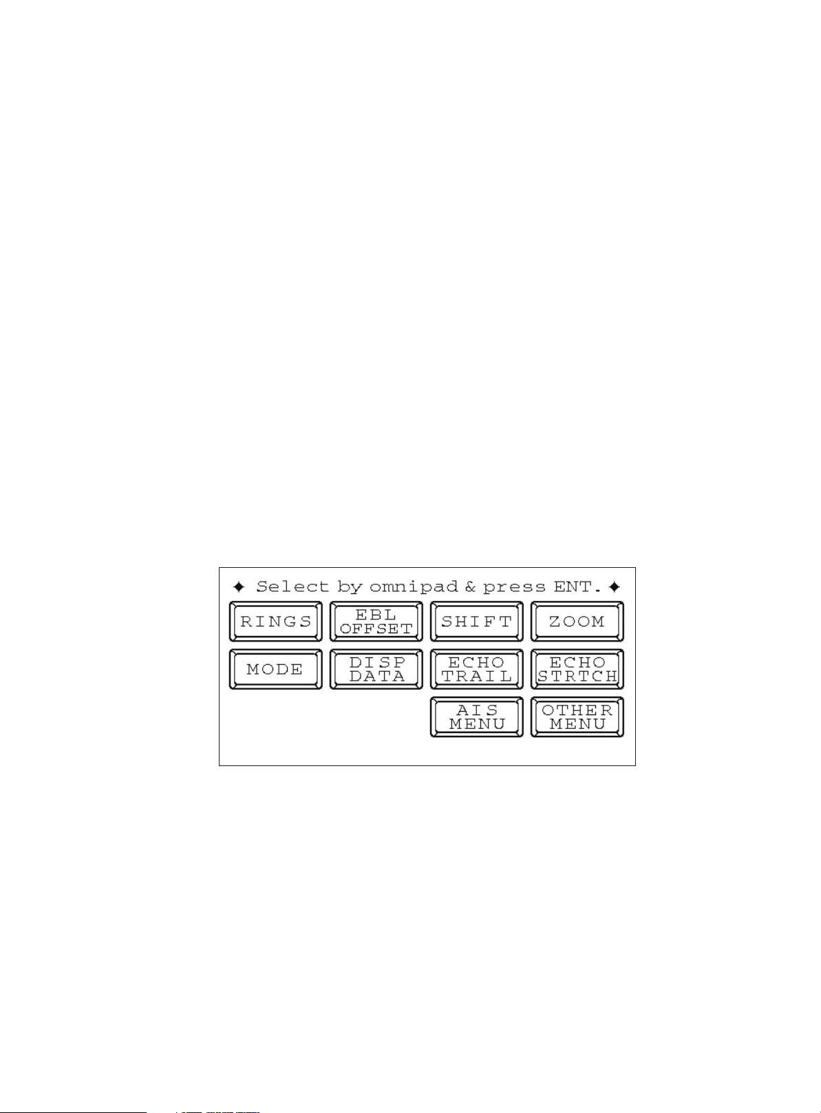
1.Press [MENU] key to open the main menu.
Figure 1 Main menu
1
Page 4

2. Select [ AIS MENU ] & press [ ACQ/ENTER ] key, Select 1.Display ,
press [ ] or [ ] key select On & p ress [ MENU] k ey t o r eturn. N ow
if AIS word appears on the upper screen of the display , The AIS symbol
is shown in the radar echo area.
[AIS MENU]
Select item by omnipad
and press ENTER key
1. Display Off On
2. Simulation Off On
3. AIS Ship listing
4. Vector Length 30s 1M 3M
6M 15M 30M
5. History Off 15s 30s
1M 2M 3M 6M
6. CPA. Set Off 0.5 1nm
2nm 3nm 5nm 6nm
7. TCPA. Set 30s 1M 2M 3M
4M 5M 6M 12M
8. Target Size
9. In/out Harbour In Out
Loss Target Alarm Off On
10.
11. Own Ship Data
Name: MMSI:
L/L: 22.45.123N Depth: 5m
115.21.369E Height: 12m
COG: 120.0 SOG: 10kt
L M S Auto
Figure 2 AIS menu
NOTE: If the AIS signal is received, the AIS function is still at work even when
the signal does not appear and still continues to ensure real time AIS information.
2
Page 5
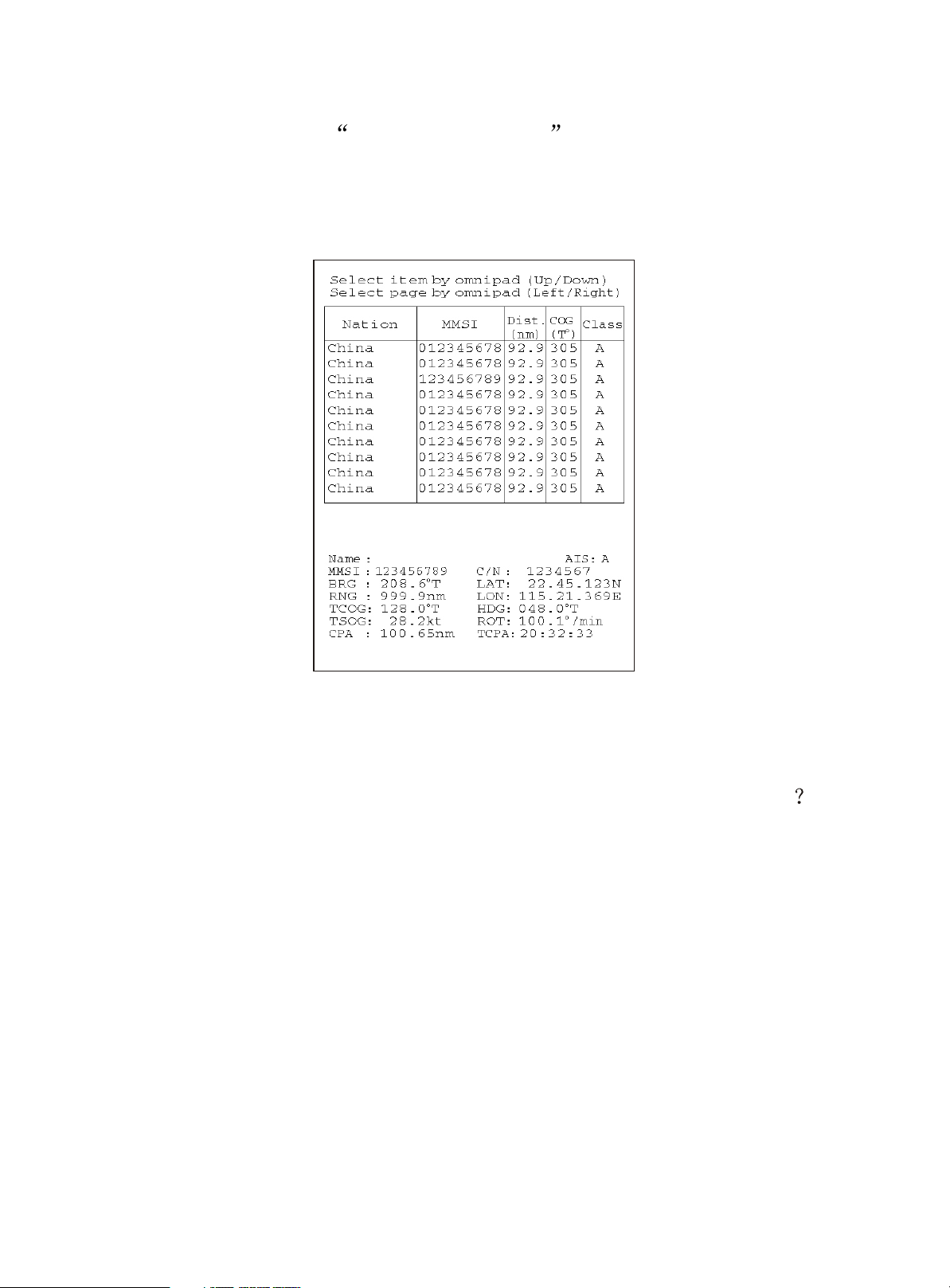
How to check the information received from Ships with AIS ?
In the AIS menu, select 3. AIS Ship Listing and press [ACQ/ENTER].
The AIS tabulation will appear and demonstrate the other ships basic
information.
Figure 3 AIS Ship Listing
How to determine the target ships detailed information
There are two methods by which we can view a ships sailing detailed
information:
1.By keyboard
From the list of AIS information, select the direction key and press
[ACQ/ENTER] , on Figure 3 , the detailed data of the current selected ship
information shall be displayed.
3
Page 6

2.By cursor
When the cursor is moved to the target ship the
and press [ENTER] key,
selected ship will appear as shown in Figure 4 and the AIS data shall appear
as shown in Figure 5.
Note: If the display setting of the radar screen is at ALL mode , it will
briefly display the AIS information as shown in Figure 6.
Figure 4 Selected target display
THGE
Figure 5 AIS Detailed data frame
Figure 6 AIS brief information
4
Page 7

How to view your ships AIS information?
Press AIS menu, select 10. Own Ship Data then AIS detailed information
will appear as shown in Figure 7.
Figure 7 Own Ship data
Setting vector length of time
This function is used to set your ship and target ships vector length. The
mark represents the vector in accordance with the present voyage. This value
is just an estimate and it will follow the ships movement. However it can
help simplify the radar operators intuitive navigation judgement.
SOG(Speed over ground)
COG (Course over ground)
Turning direction(ROT)
Heading line
(If there is no heading data, the
line points in direction of COG.)
Figure 8 Activated target
Setting method:
Enter AIS menu, select 4. Vector length and press [ACQ/ENTER] key,
then use the direction key choose corresponding time, and press the
[ACQ/ENTER] key.
5
Page 8

Past Position Display
The past position display shows equally time-spaced dots marking past
positions of activated AIS targets. A new dot is added at preset time intervals
until the preset number is reached. If a target changes its speed, the spacing
will be uneven. If it changes course, its plotted course will not be a straight
line.
Below are sample past position displays.
(a) Ship turning
(B) Ship turning
Straight
(c) Ship reduced
speed
(d) Ship increased
speed
Figure 9 Sample past position displays
Past position plot interval
Enter AIS menu, select 5.History t o s elect p lot in terval d esired: O ff,
15 s,30 s, 1, 2, 3 or 6 min. Select OFF to erase all past position points and
turn off the past position display.
6
Page 9

AIS Collision Alarm (CPA, TCPA)
The AIS continuously monitors the predicted range at the Closest Point of
Approach (CPA) and predicted time to CPA (TCPA) of each AIS target. When
the predicted CPA of an AIS target becomes smaller than a preset CPA range
and its predicted TCPA less than a preset TCPA limit, the audio alarm sounds
and the symbol of the offending AIS target becomes red, bold 2 times and
flashes together with its vector.
CPA/TCPA alarm ranges must be set up properly taking into consideration
the size, tonnage, speed, turning performance and other characteristics of
own ship.
Setting the CPA and TCPA ranges
Enter AIS menu, select 6. CPA. Set & 7. TCPA. Set , then press direction
key choose the value you want.
Below are CPA & TCPA can be setup value
CPA. Set Off, 0.5, 1, 2, 3, 5, 6 nm
TCPA. Set 30 s, 1, 2, 3, 4, 5, 6, 12 min
AIS symbol size setup
AIS symbols default has three different sizes, which can be according to
actual condition, and can also be set to automatic. When set to automatic
the size of AIS symbol will automatically change the range.
Setting the AIS symbol size
To set the AIS symbol size, enter AIS menu, select 8. Target Size and
press direction key choose L(long), M(medium), S(small) or AUTO, then
press [ACQ/ENTER] key to confirm.
7
Page 10

In/Out harbour
This function is used to avoid ships in the harbour because too many AIS
boats nearby may cause continuous alarm. Upon entering the port you may
select "ON" , CPA and TCPA alarm will be disabled.
Setting IN/OUT harbour
Enter AIS menu, select 9. In/Out Harbour , use direction key
to
set.
Loss target alarm function
If the current range of AIS targets within the information given by the
maximum update interval had not yet received, will be loss target alarm
function is triggered, in this case, the target becomes the symbol shown
below loss target mark, symbol color is red and flash, while the radar alarm
will sound to remind the operator out to pay attention. To manually stop the
audible alarm, press the [SELECT/CANCEL] key once.
Figure10 loss target display symbol
How to open the loss target alarm function
Did not turn this function on the LOSS target symbol will still be displayed,
but does not trigger the alarm. Start as follows:
1. Into the AIS menu and select "10. Lost target alarm";
2. Press the arrow keys to select "On" and press the [ACQ/ENTER];
3. Press [MENU] key 2 times to exit.
8
Page 11

Prompted of data processing
The radar system can access a variety of NMEA data, including AIS / GPS,
direction and water depth data. At boot time, if not turned on AIS, the radar
will appear on-screen prompts such as: "No AIS device." To know there are
many, such as "AIS signal loss" etc. To turn off the prompt, press the
[ACQ/ENTER] key.
AIS symbol colour
When the background color is black, the echo color is yellow, AIS symbol
colors are set as follows:
Figure 11 Black background & yellow echo
Own ship: White triangle
CLASS A: Blue triangle
CLASS B: Green triangle
BASE STATION: Blue square
Selected ship:
Alarm ships Red triangle bold 2 times & flash
ALL circles: Without direction information target
Echo color is green:
CLASS A: Yellow triangle
BASE STATION: Yellow square
Broken square is overlaid on
9
Page 12

Blue background color & multi echo color
Figure 12 Blue background & multi color echo
10
Page 13

AIS ship symbol status description
SYMBOL
STAT US REMARKS
Sleeping target
Activated target
ROT higher than preset
ROT
Target selected for data
display
Dangerous target
An isosceles, acute-angled triangle should be used
with its centroid representing the target's reference
position. The most acute apex of the triangle should
be aligned with the heading of the target, or with its
COG, if heading information is not available. The
symbol of the sleeping target may be smaller than
that of the activated target.
All AIS symbols shown with thick line. Color is
selectable from menu.
Displayed for turning ship.
Broken square is overlaid on target selected to
display its data.
Displayed when CPA/TCPA is within CPA/TCPA LIMIT.
Red in color. Flashing .u ntil acknowledged.
Lost target
“\” overlaid on a lost target. Erased after
acknowledged.
Figure13 AIS ship symbol description
Other symbol description
Other AIS symbols that may appear are shown in the table below.
SYMBOL Meaning
Real AIS AtoN
Virtual AIS AtoN
Base Station
Airborne SAR aircraft
Figure 14 Other symbol
11
Page 14

Menu Tree
MENU KEY
RINGS(Off,1,2,3,max)
EBL OFFSET Off On
SHIFT Off On
ZOOM Off On
MODE HU CU NU TM
DISP DATA
ECHO TRAIL Off On
ECHO STRTCH Off ES
AIS
MENU
OTHER MENU
.Panel Dimmer
1 1,2,3,4
.Mark Brill
2 1,2,3,4
.HD Mark
3 1,2,3,4
.Characters
4 1,2,3,4
.Trail Tone Single Multi
5
.Int Reject Off
6 1,2,3
.Pulselength Short Long
7
.Noise Reject Off On
8
.Trail Time
9
15S 30S 1M 3M 6M 15M 30M Cont
.Tone Auto Manu
10
.Disp Data Off Nav ARP All
11
.WPT Mark Off On
12
.EBL Ref Rel True
13
.VRM Unit nm km sm
14
.Watchman Off
15 5M 10M 20M
.STBY DISP Norm Econo Nav
16
.Guard Mode In Out
17
.Cursor Posi
18 B/R,L/L
19.Alm Sense LV Low Mid High
.Dead Sector Off On
20
.Range
21
1/8 1/4 1/2 3/4 1 1.5/2 3 4 6 8 12 16 24,
22.Color Setting
23.Self Test
24.Installation Setup
1 ES2
.Display
1
.Simulation
2
.AIS Ship listing
3
.Vector Length
4
.History
5
.CPA. Set
6
.TCPA.Set
7
.Target size
8
9.In/out Harbour
10. Loss Target Alarm
11.Own ship Data
36):1016
36,48):1048
36,48,64):1064
.Nav Talker All
1 GPS
.Depth unit m fa ft
2
.Temp Unit , )
3CF
.Hdg Sensor(Magnet,Gyro)
4
.Key Beep Off On
5
.Scan Stop Rotate Stop
6
.Dead Sector
7
.Tune/Video Adjustment
8
.Heading Alignment
9
.Sweep Timing Adjustment
10
.MBS Adjustment
11
.Ant Height Low Mid High
12
.STC Curve(Sharp,std Gntl)
13
.Ope Mode Master Slave
14
.Hours in Use
15
.TX Hours
16
12
Page 15

NMEA Interface specifications
1. NMEA1 (6 pins connector)
1.+3.3V 2.NMEA1 Input+ 3.NMEA1 Input 4.GND
5.AIS/GPS select
Note:
When NMEA1 Otherwise,
leave open for GPS connection
NMEA1 Connector for AIS connection
is used for AIS connection, short-circuit pin 4 and pin 5.
.
2
5
3
4
AIS +
AIS -
2
5
3
4
NMEA1 Connector for GPS connection
GPS +
GPS -
2. NMEA2 (8 pins connector)
1.+12V 2.NMEA2 Input+ 3.NMEA2 Input 4.GND
5.+12V 6.NMEA3 Input+ 7.NMEA3 Input
Option
Power
GND
CAUTION
Ground the equipment.
Ungrounded equipment might
emit or receive electromagnetic
interference or cause electrical
shock
Fuse Holder
Upgrade
NMEA-1 Connector
NMEA-2 Connector
Figure 15 Display connect
GND
CAUTION
Replace ther fuses to
5A for 24/32VDC
operation
13
Page 16

 Loading...