

Onwa KR-1338, KR-1668 Service Manual

KR-1338/1668
άÐÞÊÖ²á
KR-1338/1668
SERVICE MANUAL
10.4 TFT COLOR MARINE RADAR


TABLE OF CONTENTS
1.GENRAL 1
2.BLOCK DESCRIPTION 6
1.1 Outline 1
1.2 Boards & Major Components 2
1.3 Specifications 3
2.1 Overview 6
2.2 Display Unit 7
Block Diagram of Power Supply 9
Block Diagram of Processor PCB Main 0910 10
2.3 Transceiver Unit 14
Block Diagram of IF 0711 15
Block Diagram of Modulator 17
2.4 Different Points of Similar PCBs 18
3. ADJUSTMENT 19
3.1 Adjustment of Display Unit 20
3.2 Adjustment of Scanner Unit 29
Location of Parts on MAIN 0910 24
VIDEO Signal adjustment 25
Location of parts on PWR-0913 28
Location of parts on MOD-0904 30
Location of Parts on IF-0711 31
Location of PCBs in Transceiver Module (KR-1668) 32
BEARING SIG GEN Board (HBP0904) 32
Location of Parts on MOD 0904B 33
Location of Parts on IF-0711 34
4. MAINTENANCE 35
4.1 Remarks on Replacement of Major Parts 35
4.2 Life Expectancy of Expendable Parts 36
4.3 Menu tree 37

5.TROUBLESHOOTING 38
5.1 Outline 38
5.2 Troubleshooting Flow Charts 39
5.3 Message Indication 51
Display Unit Exploded view 52
Scanner Unit Exploded View 54
Schematic circuit diagram 58

1. GENERAL
1.1 Outline
This manual provides the information necessary for the servicing and adjustment
of the radars MODEL 1338, 1668.
The antenna unit uses a Log IF amplifier.
The table below shows the major specifications of the each model. The same
program is installed on all models, but the menu setting through factory menu is
different between the models.
Functions KR-1338
KR-1668
Maximum range
Program Number
Tuning Voltage
(displayed at manual tuning)
Antenna Rotation
Antenna Rotation
36 NM 64 NM
4.9 V to 32V
about 24 rpm
4 kW
4/6 kW
KR-1338-SME-1
The major parts and P.C. Boards used in the display and scanner units are tabulated
on the next page.
1002XX XX
1

1.2 Boards & Major Components
Board
KR-1338 KR-1668
DISPLAY
UNIT
SCANNER
UNIT
PROCESSOR Board
POWER SUPPLY Board
FILTER Board
PANEL Board
MODULATOR Board
IF AMP Board
RTB Board
BEARING SIG G
EN Board
MIC Board
MIC
Magnetron
Circulator
Scanner Motor
Signal Cable
MAIN 0910
PWR 0913
FIL 0912
KEY 0912
MOD 0904A
MOD 0904B
IF 0711
-
HBP 0905
-
RCN 0907
NJT-1968B
MAF1421B/MSF1421B
MAF1421/MAF1422B
KRC-003-10(10m)
KRC-003-15(15m)
KRC-003-20(20m)
KRC-003-30(30m)
KR-1338-SME-2
CON 0906
FCX73C
BM-8256
-
BM-9256
Cable
2
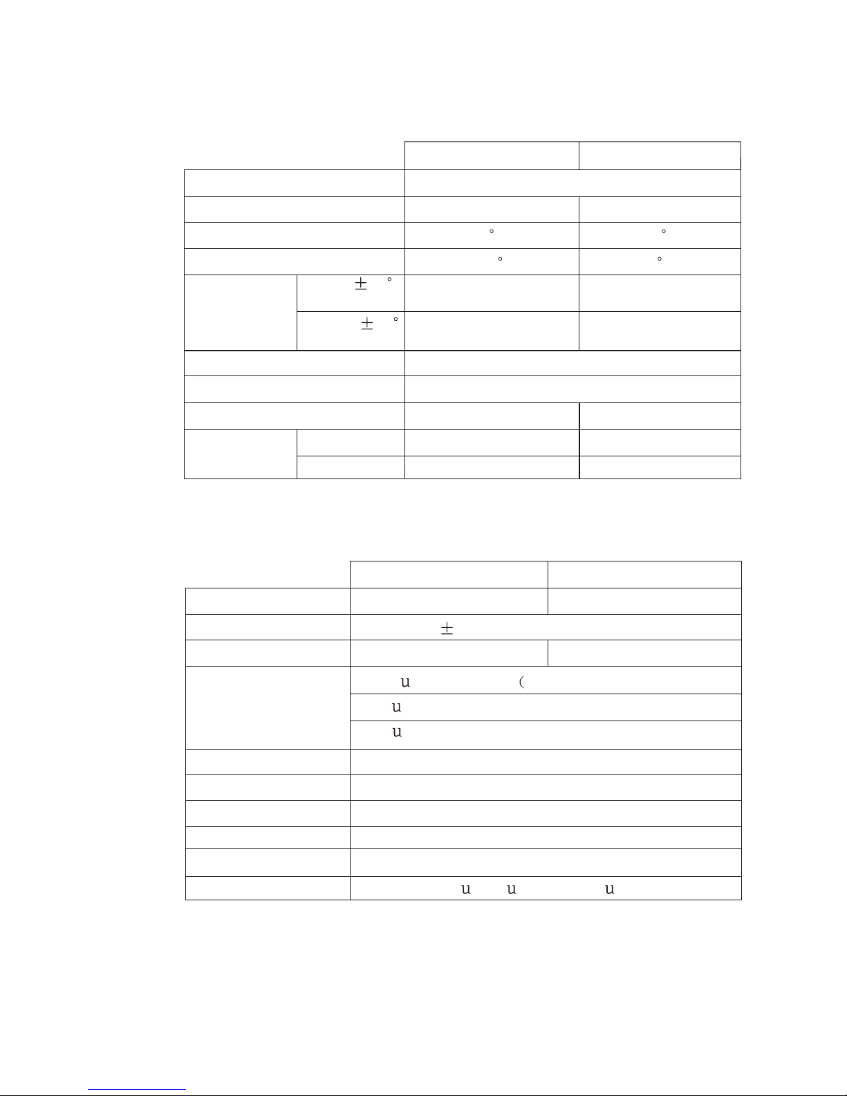
1.3 Specifications
SCANNER UNIT
KR- 1338
KR-1668
Radiator Type
Radiator Length
Horizontal Beamwidth
Vertical Beamwidth
Slotted Waveguide Array
56cm
120 cm
4 1.9
20 22
Sidelobe
Attenuation
Within 20
of mainlobe
Outside 20
of mainlobe
Polarization
Antenna Rotation
Scanner Housing Stureruct
Compass Safe
Distance
-18 dB or less -24 dB or less
-23 dB or less
-30 dB or less
Horizontal
24 rpm nominal
Radome
Open nominal
Standard
Steering
0.9 m
0.7 m
1.0 m
0.74 m
TRANCEIVER
KR-1338 KR-1668
MAF1421/MAF1422B
KR-1338-SME-3
Magnetron
Frequency &Modulation
9410 M z 30M z,P0N
HH
Peak Output Power
4 kW nominal
6 kW nominal
Pulse Length &
Pulse Repetition
Rate
0.3
Modulator
Duplexer
Receiver Front End
Tuning
Intermediate Frequency
Bandwidth
FET Switch
Circulator with diode limiter
MIC(Microwave IC)
Automatic or Manual
60 M z
H
25 M z(0.08
H
Short Ranges:0.25 nm -1.5 nm)
S, approx 2100 Hz
0.08
S, approx 1200 Hz(Middle Ranges: 1.5nm - 3nm)
0.8
S, approx 600 Hz(Long Ranges: 3 nm and above)
S, 0.3 S), 3 M z (0.8
H
S)
KR-1338-SME-4
MAF1421B/MSF1421
3
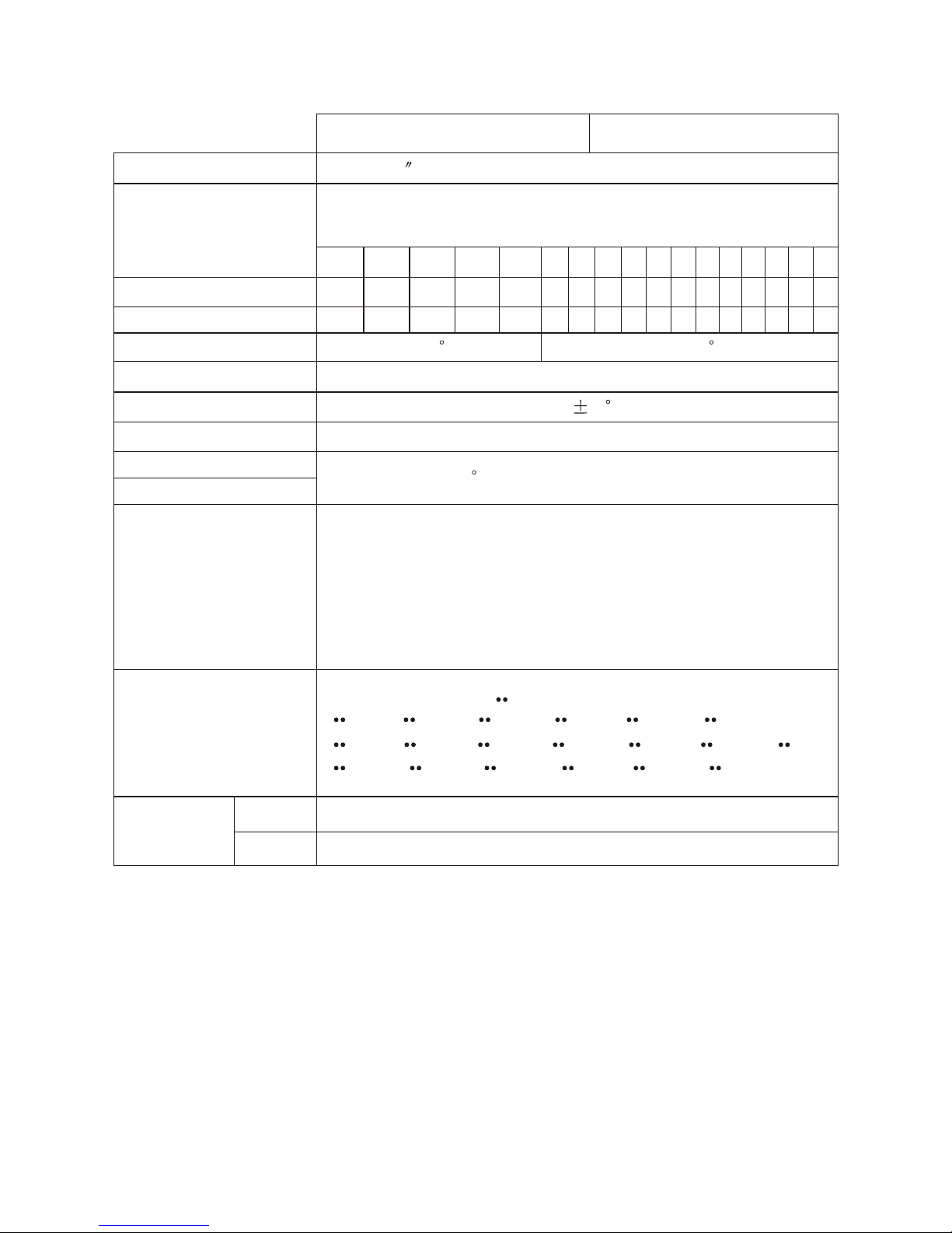
DISPLAY UNIT
KR- 1338 KR-1668
Picture Tube
10.4 LCD(LED backlight ,32 bit TFT color LCD)
Range Scale(nm)
KR-1338:36 nm
KR-1668:64 nm
0.125 0.25 0.5 0.75 1 1.5 2 3 4 6 8 12 16 24 36 48 64
1/16
0.125 0.125 0.25 0.25 0.5 0.5 1 1 2 2 3 4 6 12 12 16
2 2 4 43 3 4 4 4 4 4 4 4 43 3 3
4 1.9
Range Ringe Interval
Number of Rings
Bearing Resolution
Range Discrimination
Bearing Accuracy
Minimum Range
Range Ring Accuracy
VRM Accuracy
Input/Output Terminal
Nav Data
Compass safe
Distance
Better than 20 m
1
Better than 25 m
0.9 or 8m,whichever is the greater
NMEA (three input): NMEA 0183
NMEA (output) :NMEA 0183($RATLL, $RARSD, $RATLL:
Internal easy ARPA version.)
External Buzzer (output) : +12 V source pulse Open Collector
Slave Display (output): TRU-HD, BP, TRU-TRIG, VIDEO
NMEA 0183 Format ( :any talker)
$ APB, $ BWC, $ BWR, $ D
$ GLC, $ GTD, $ HDG, $ HDM, $ HDT, $ MDA, $ MTW,
$ RMA, $ RMB, $ RMC, $ VTG, $ VHW, $ XTE,
PT, $ GGA, $ GLL,
Standard
Steering
0.75 m
0.6 m
KR-1338-SME-5
4
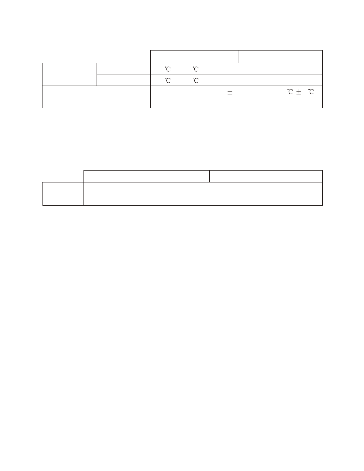
ENVIRONMENTAL CONDITIONS
KR-1338
KR-1668
Ambient
Temperature
Scanner Unit
Display Unit
Humidity
Vibration
-25 to +70
-15 to +55
Relative humidity 93% 2% or less at +40 3
-IEC 60945
KR-1338-SMJ-6
POWER SUPPLY & POWER CONSUMPTION
KR-1338 KR-1668
DC Power
10.5 V to 40.0V
48 W approx
56 W approx
KR-1338-SME-7
5
2. BLOCK DESCRIPTION
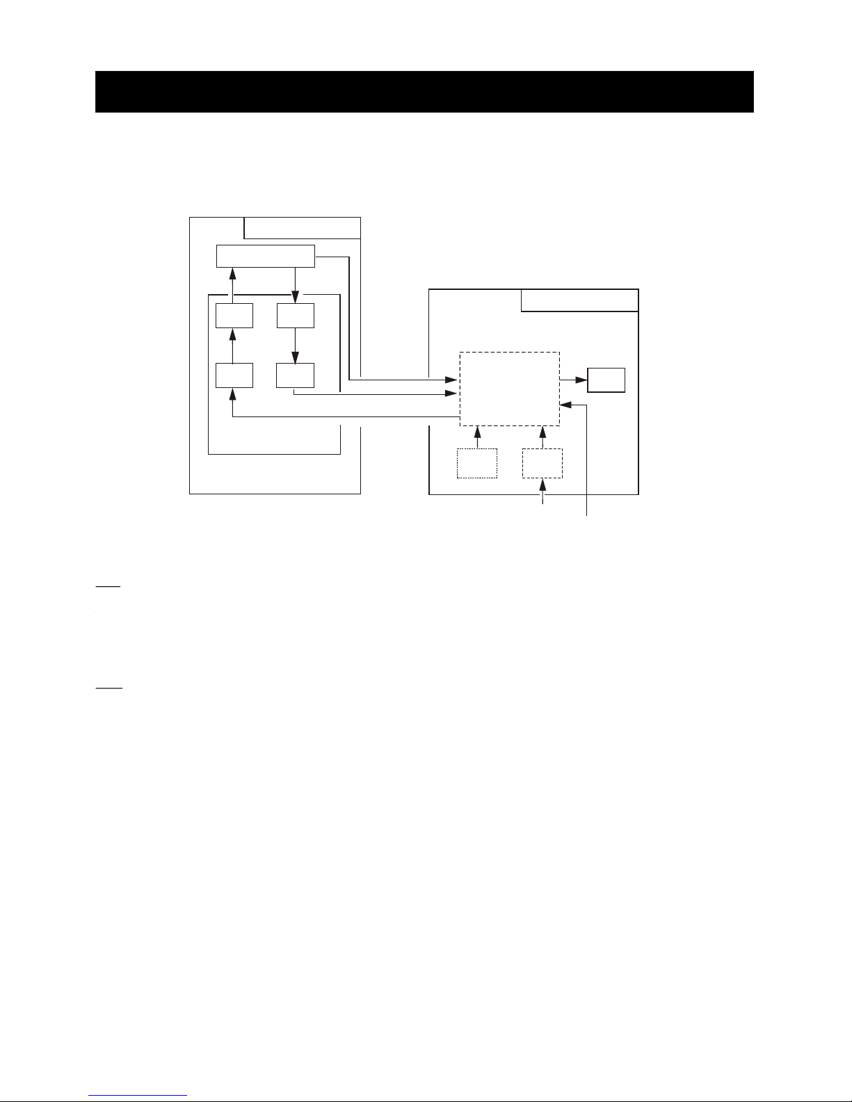
2.1 Overview
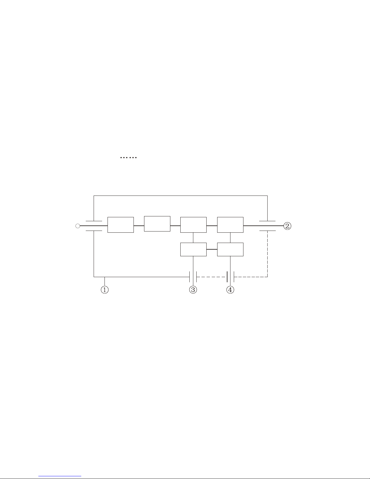
The simpified block diagram of the system is illustrated below.
TX
The trigger pulse from the PROCESSOR Board is delivered to the MODULATOR
Board, oscillates the magnetron, and then radar wave is emitted from the radiator.
RX
The 9.4 Ghz echo signal received by the antenna is converted to 60 Mhz signal by
the MIC, amplified by IF Amp, and fed to the PROCESSOR Board as video signal.
It is digitally processed and then displayed on the LCD.
Scanner Unit
Antenna
Mag. MIC
IF
Amp
Mod.
RF Module
Processor
LCD
Panel Power
Display Unit
Ship s mains'
Nav.
Gyro
HD.BP
Video
Trigger
6

2.2 Display Unit
Power Supply Circuit (PWR 0913)
The constant voltage generator Q1 is in operation even when power switch is off,
ship s mains is supplied. The power supply circuit is basically consists of a main
inverter and a sub inverter. The main inverter derives the isolated line voltages
+12 V/ANT+12 V and -12 V/ANT -12 V from the main input. The sub inverter
derives +5 V and +32 V from +12 V output of the main inverter.
Main inverter
The PWR switch becomes "open" when it is set to on position.
When the PWR switch is pressed, about 9 V is input via PWR line (P1302 #13),
Q2 is on, and DC+10 V is applied to the PWM.
When power is supplied to the PWM controller, it starts operation and alternately
turns on and off two switching FETs Q3/Q4 connected to the primary widing of
T1. The resultant AC voltage obtained on the secondary windings are rectified and
smoothed to +12 V and -12 V, and delivered to various circuits in the equipment.
The voltage taken from the +12V line is fed back to the PWM controller through
the Vr1 to maintain the +12 V output constant.
Sub inverter
U5 and the associated circuit form a PWM switching regulator for +5V and +32V.
The voltage taken from +5 V line is fed back to U5 through R37 resistance to
maintain the +5 V output constant.
Protectors
Protection of power supply circuit is achieved by stopping the drive signals to the
switching FETs Q3/4.
'
7

Qverload on +5 V and + 32 V line is detected by U6. Overload on +12 V(MOTOR+)
line is detected by U7. When the +5 V and + 32 V line is reduced by a heavy load,
U6 or U7 becomes condctive and consequently disables the PWM controller through Q6, Q7 and Q8. Overcurrent on the main input line is detected by R13, R14
and R15. The voltage drop across Q6, Q7 and Q8 bec- omes large when the inverter is overload. Overcurrent detector U3 disables PWM inverter U2 when the
voltage drop exceeds a certain level.
Overvoltage of mains input is detected by the U1. When the input voltage exceeds
41.6 V, the U1 becomes active and disables PWM controller U2
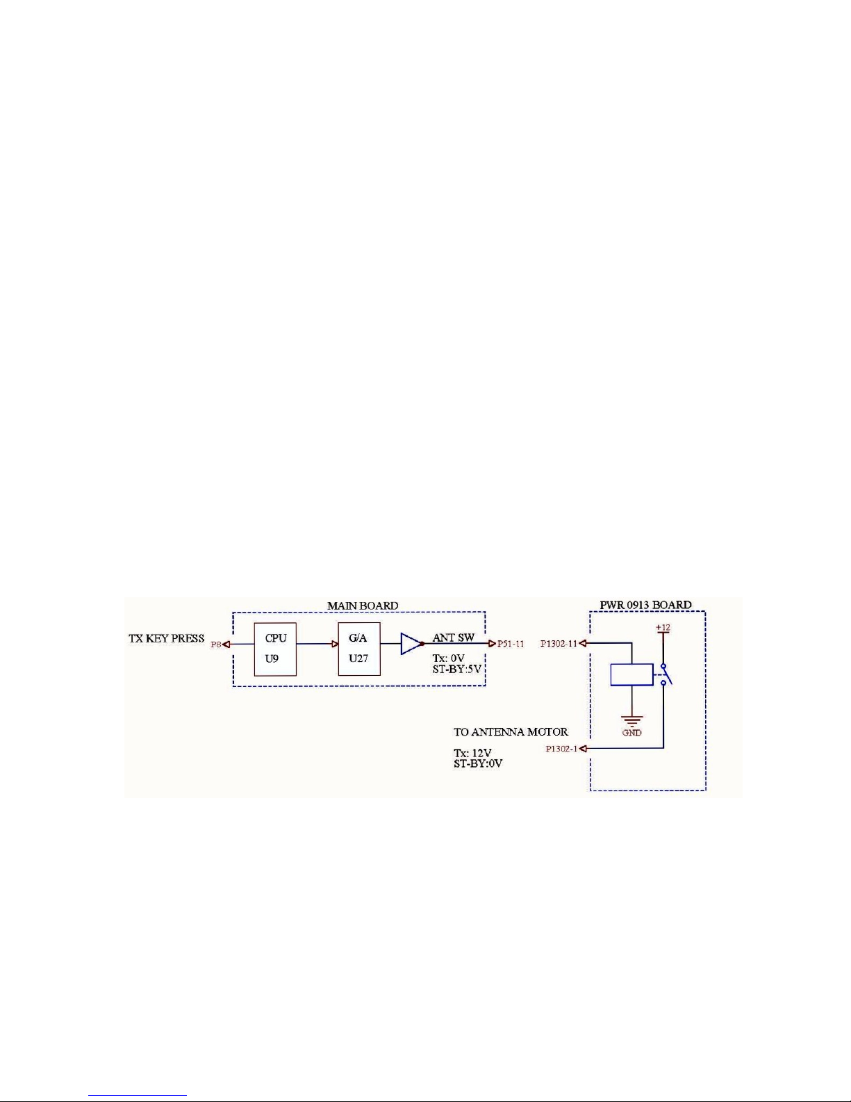
Scanner motor power (ANT+12V/ -12 V)
+12 V and -12 V (ANT +12 V/ANT -12 V) are used to drive 24 V scanner motor.
The power to the motor is turned on/off by the relay(K1) on the POWER SUPPLY
Board. The relay control signal from the SPU Board is supplied to Q52 and Q53
on the POWER SUPPLY Board. Pressing the TX key changes the ANT SW signal
state from 5 V to 0 V, and K1 is on to supply +12V.
.
8

BLOCK DIAGRAM OF POWER SUPPLY
9
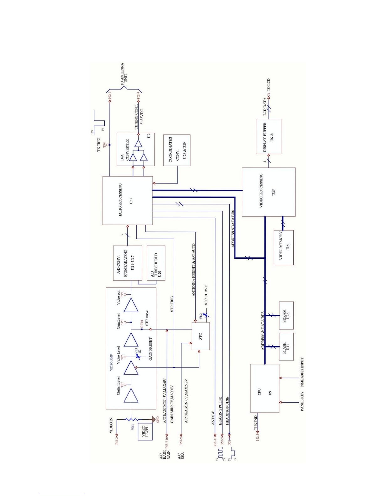
BLOCK DIAGRAM OF PROCESSOR PCB MAIN 0910
10
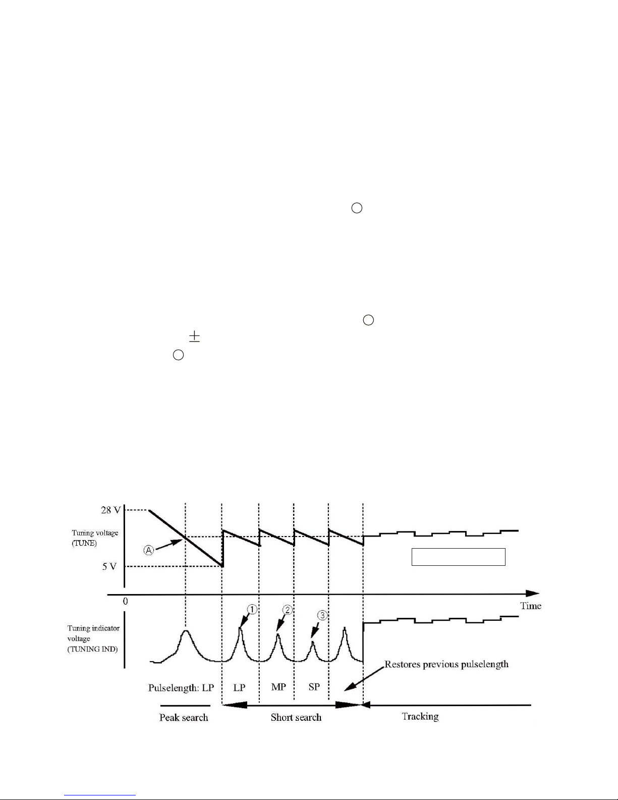
AUTOMATIC TUNING
There are two types of automatic tuning: peak search and short search. The tuning
voltage differs from model to model.
KR-1338/1668 : 5 V to 28 V
Peak search: Tuning voltage (TUNING), point in the figure below, is searched
in the tuning voltage range 5V to 28V. Tuning In voltage
(TUNING IND) is maximum at point .
Search conditions: After initial tuning adjustment.
Search time: 3 sec approx
Short search: Maximum tuning indicator voltage is searched in the tuning
voltage range of 2.5V.
1)After initial tuning adjustment.
2)When tuning method is switched from manual to automatic.
3)When the radar is switched from ST-BY to TX.
4)When a range where pulselength is changed from short to middle
and from middle to long is selected.
Tracking: After short search, tracking takes place.
Tracking voltage: 0 V to 32 V
dicator
A
A
A
KR-1338/1668
11
TUNING INDICATOR
After tuning adjustment, peak TUNING IND voltages, , and in the figure
on page are stored on to EEPROM.
The automatic and manual tuning point is also memorized. Using these data,
the tuning indicator extends more than 80% on ALL TX pulses.
Note that the extension on short pulse is shorter than on long pulse. The indication becomes shorter with the magnetron deteriorated.
MANUAL TUNING
The manual tuning voltage changes from 5 to 32 V on M 1668 at the steps
of about 0.1 V.
Manual Tuning is carried out by using omnipad: pressing "Right" side in-
creases.
The TUNING continue voltage displayed on the screen differs by about 1V
from the measured voltage at P52 # 9. Manual Tuning and tuning adjustment
are required when automatic tuning is abnormal (that is ,low sensitivity).
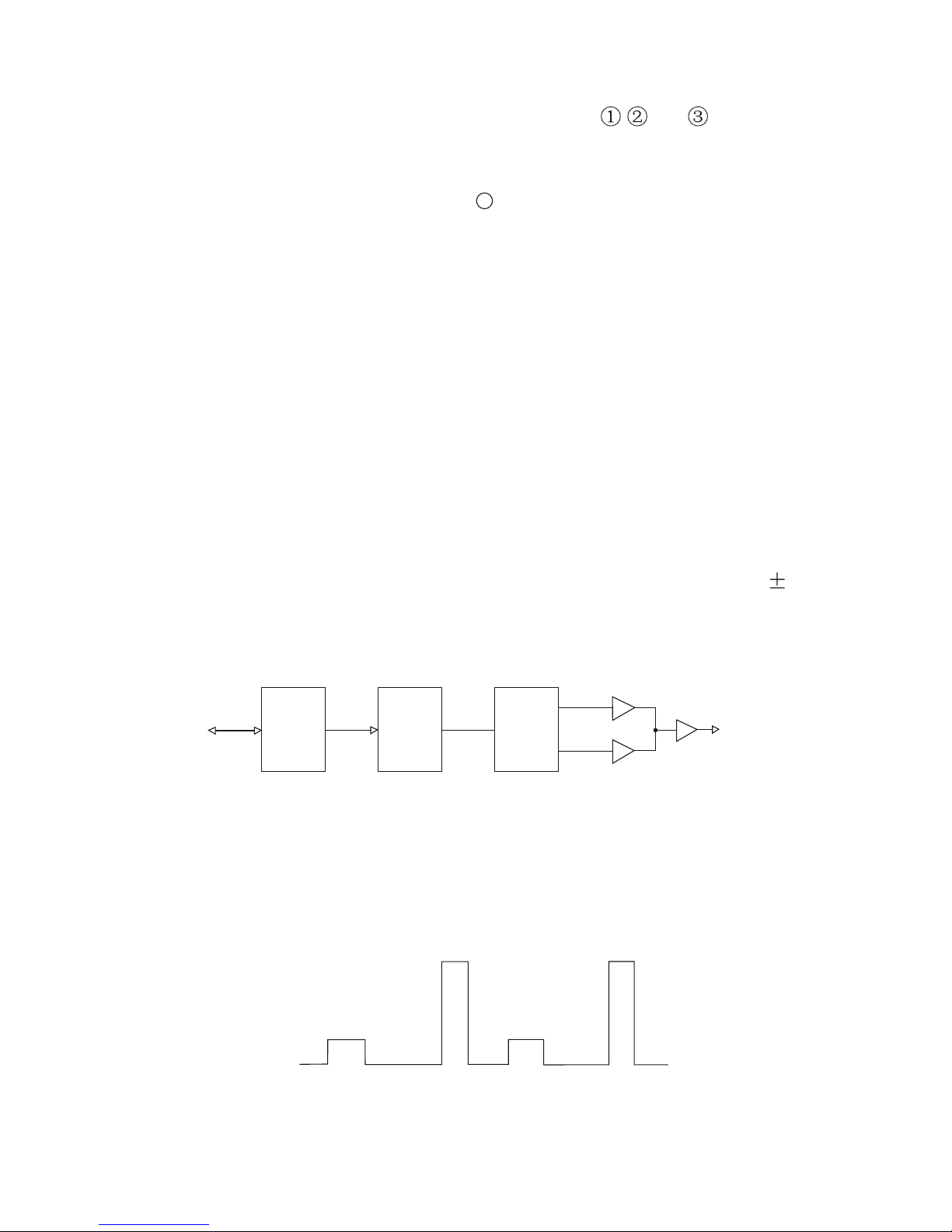
TUNING CONT. Operation (from power-on stand-by)
A square wave is automatically output as a TUNING CONT signal during standby just after power-on the model as follows.
2-5
A
0V
5V
34V
F VT
C VT
KR-1838/1968/1948
FROM PANEL BOARD
P8
CPU
U9
P/S
CONV.
U27
D/A
CONV.
U20
CVT
FVT
#5#3#7
U2
#1
#10
#8
P8
TUNING CONTROL
(TO RF UNIT)
12
Heading and NAV data
Heading data in NMEA format HEADING DATA (HDT, HDG, HDM, VHW)and
NAV data (NMEA-0183)can be input from any NMEA input connection. THE
data from the KEY board(KEY 0912) to P8#3 of MAIN board .
NOTE:
1.If only one NMEA signal input may select any connection, if several connections
have time the signal input, be please main and the most commonly used signal
meets in the connection 1, because the complete signal's input is 1 comes the
synchronization by the connection, i.e. the connection 1 signal is fastest;
2.The NMEA signal after or before radar starting in may, but in signaling process,
if the NMEA port 1 loss of signal, will possibly cause other port data not to be
able to transmit normally. Must remove this kind of condition only to be able again
starting.
Turning on/off antenna rotation
The SPU board controls antenna rotation. In normal operation, the antenna
rotates during the TX condition. However, the antenna can be stopped during
the TX condition thru the Installation setup menu.
13
2.3 Transceiver Unit
MIC
The following description is for reference only.
As a general rule of thumb, the radar requires better noise figure (NF) and better
dynamic range. Both factors, however, are reciprocal. The NF affects long range
performance, while the dynamic range dose short range performance.
To improve noise figure, amplifier and MBS circuit into the MIC, RU-9360.
MIC w/RF amplifier NJT-1968B(MODEL 1338/1668)
IF OUT
(+5V to 35V)(+5V)GND
RF IN
W.G.TO
COAX CONV.
LIMTER
FET AMP
DOUBLEBALANCED
MIXER
POWER FET OSC.
Block Diagram of MIC NJT-1968B (MODEL 1338/1668)
14
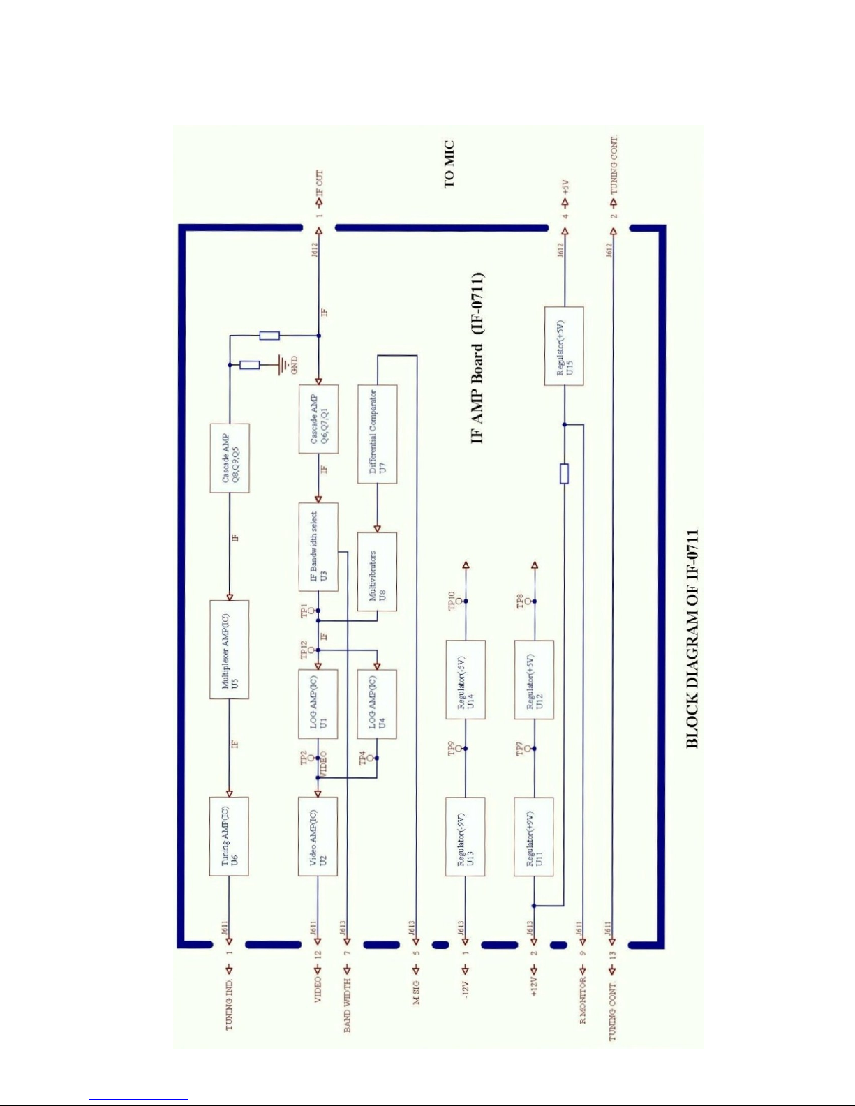
BLOCK DIAGRAM OF IF 0711
15
Modulator
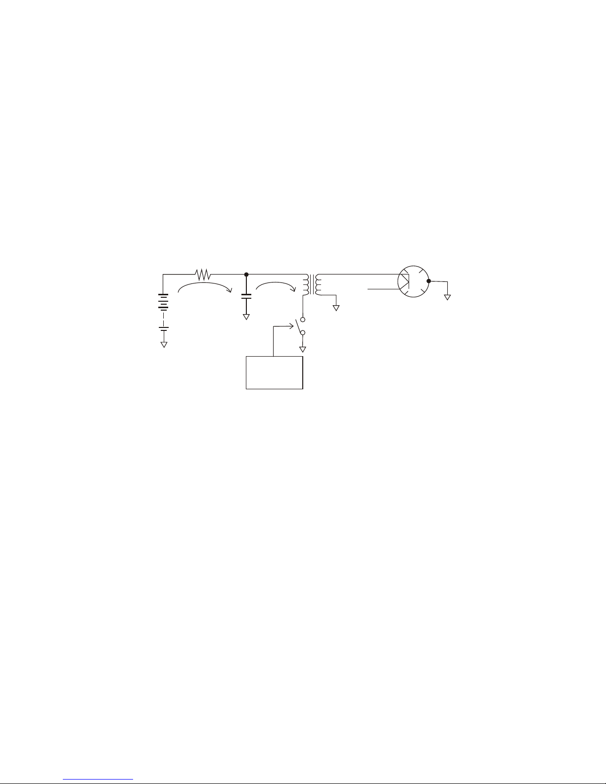
PRINCIPLE OF FET SWITCHING MODULATOR
High voltage is charged into C through R while the magnetron is inactive.
When the trigger is applied to the power MOS-FET, the FET turns on and the high
voltage appears at the primary winding of the pulse transformer. This transformer
boots the voltage, which makes the magnetron oscillate.
One advantage of this method is that the magnetron oscillates only when the FET
is conducive, that is the transmission pulsewidth can be changed by the TX trigger
pulsewidth. Therefore, parts such as relay and coil can be eliminated.
MODULATOR BOARD MOD-0904
The main function of the modulator section is to produce high voltage pulses to
drive the magnetron. To produce these pulse, the MODULATOR Board has a
modulator trigger circuit, modulator pulse generator and booster pulse transformer.
The modulator trigger circuit consists of U805 and associated components. This
circuit generates the pulses which cause modulation FETs Q805,Q806 to conduct.
The pulses are produced when the TX TRIG pulses from the display unit is received and U805 conducts. The voltage of the pulses is raised at pulse transformer
T802 until it is 3.5 kV. This circuit adjusts the electrical curent flowing into the
magnetron so it is 3 A.
The MODULATOR Board also contains the TX high voltage circuit and the magnetron heater circuit. The TX high voltage circuit charges capacitors with 300 V
high voltage produced at the primary windings of T801 and discharges them once
the TX TRIG pulse is received. The magnetron heater circuit produces stable +7.5V.
Modulator section simple block diagram
R
PULSE TRANS
MAGNETRON
HIGH VOLTAGE
MOST-FET
Charge
Discharge
TRIGGER
C
D
16
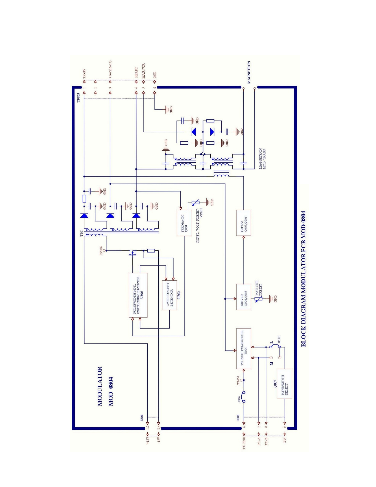
BLOCK DIAGRAM OF MODULATOR PCB MOD 0904
17

2.4 Different Points of Similar PCBs
1. How to set SPU (MAIN 0910) Board
This board is set at factory for use in the KR-1338. For use in the or 1668, change
the factory menu as below.
While pressing and holding down the GAIN(HM-OFF) control, press the [MENU]
key five times to display the factory menu.
1) MAX range
36 nm: KR-1338, 48 nm: KR-1648, 64nm: KR-1668
2) Type
R: Regular, G: German, N:Netherland, K:Korea
3)Model
Selects the Antenna Unit.
KR-1338 KR-1648 KR-1668
4)Language
CHN: Chinese English
5)Default Setting
Default settings (except factory menu) can be restored by selecting Default Setting
and pressing the [ENTER] key three times. Restart radar settings. After changing
the setting, the installation adjustment (heading, timing, etc.) Must be carried out
again.
2.MODULATOR board MOD-0904 A/B
E version of MOD-0904 is not compatible with A version. This is because B has a
larger pulse transformer.
[Factory MENU]
1. Max Range 36 48 64
2. Typ e R G N K
3. Model KR-1338 KR-1648
KR-1668
4. Language ENG CHN
5. Default Setting ENTER 3
<Press MENU key to escape >
M1338-SME-09D
18
 Loading...