

Page 1

KP-622/623/823
˵Ã÷Êé
˵Ã÷Êé
OPERATOR`S MANUAL
3 Series GPS Chart Plotter
R
KP-622/623/823
Page 2

Page 3
P roduct Introduction
1
Page 4

CONTENTS
P 1roduct introduce
Foreword 4
1. Keypad instruction 5
2. Basic Operation 6
2.1 Display 6
Plotter screen 7
Navigation screen 8
Route screen 8
Positioning screen 8
2.2 Operation 9
Turning the power on/off, adjusting the brightness and contrast 9
Waypoint establishment and ship's position storage 9
Delete waypoints 10
Single point navigation and cancel navigation 11
Route setting and route navigation 11
Track record 13
Emergency (MOB) navigation 17
3 Main Menu 18
GPS 18
Route 18
Point 18
Barrier 19
2
Page 5
Alarm 20
Tide 20
Unit 20
Setup 21
In/Out 21
4. AIS function of 3 Series 22
Start AIS function 22
Vessels list 22
The collision alarm 22
Own ships information 23'
Chart Screen 23
View AIS vessels' information on chart screen 24
Check all AIS ships within the scope of Radar 24
Emergency alarm 25
Entry/Departure setting 25
Navigation Terms 26
5. Main performance and specification 27
Performance and characteristics 28
Equipment parameters 28
Equipment configuration 29
Installation 30
3
Page 6
FOREWORDFOREWORD
The ONWA 3 seriesof ONWA GPS navigation aid are specially designed for the
vessel traffic management, ONWA is a professional brand of the domestic and for-
eign navigation products.
The products are designed to be all-sealed and waterproof, can be rapid position-
fixing and resistant to poor environment. The software is powerful by using the
advanced ARM9 processors can be capable to display faster, and the design for
operation is professional and reasonable, can be easy to use. The built-in Large-
capacity map storage space provides intuitive and accurate indication to navigation.
It s applicable to the navigation and position-fixing of various vessels at sea and
'
rivers, as well as the information collection, river management, etc.
For the application for different types of the products please refer to the following
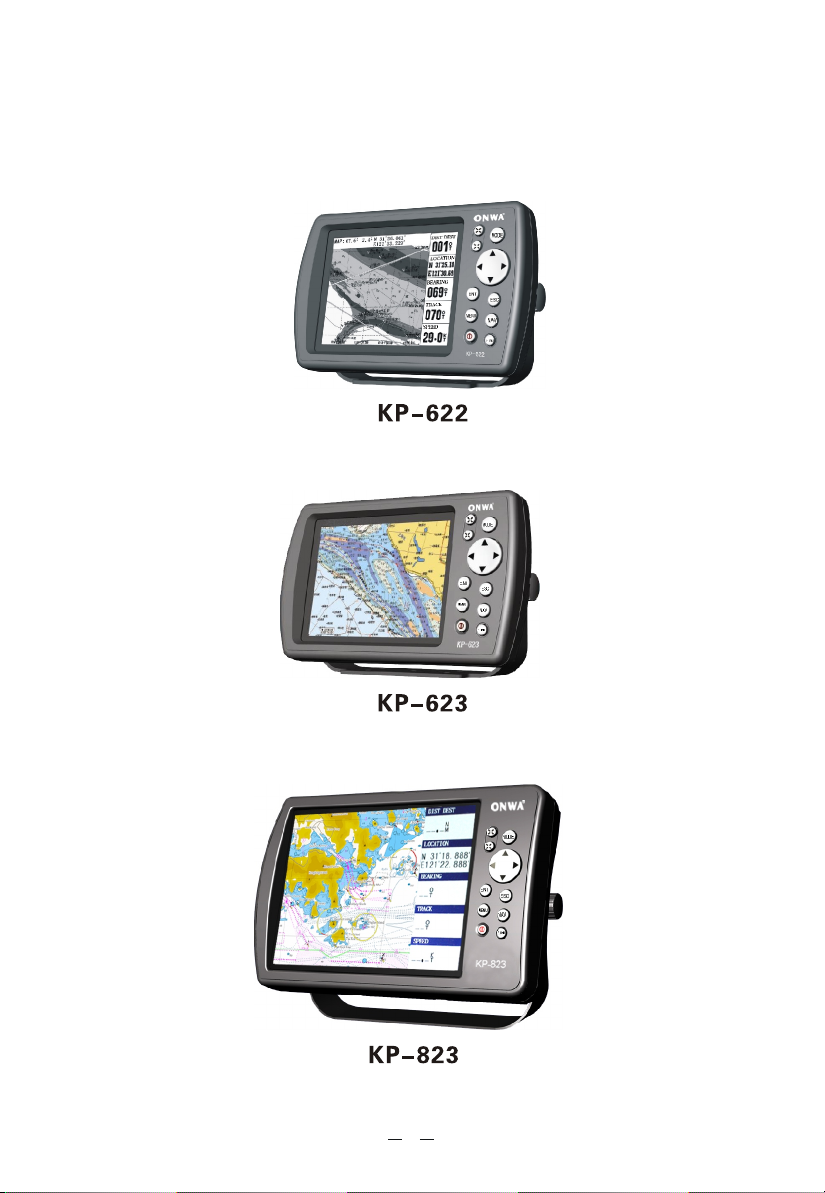
KP-622
pleasure craft
5.7 FSTN 8 grades of grey
5.7 TFT bright, color Available
8.0 TFT bright, color
hydrographic
Type Display AIS interface Application Scope
Available
Inland river, lake and sea
Available
Harbor shipping, fishing,
Inland river, sea and
Harbor shipping, fishing,
Inland river, lake and sea
4
Page 7
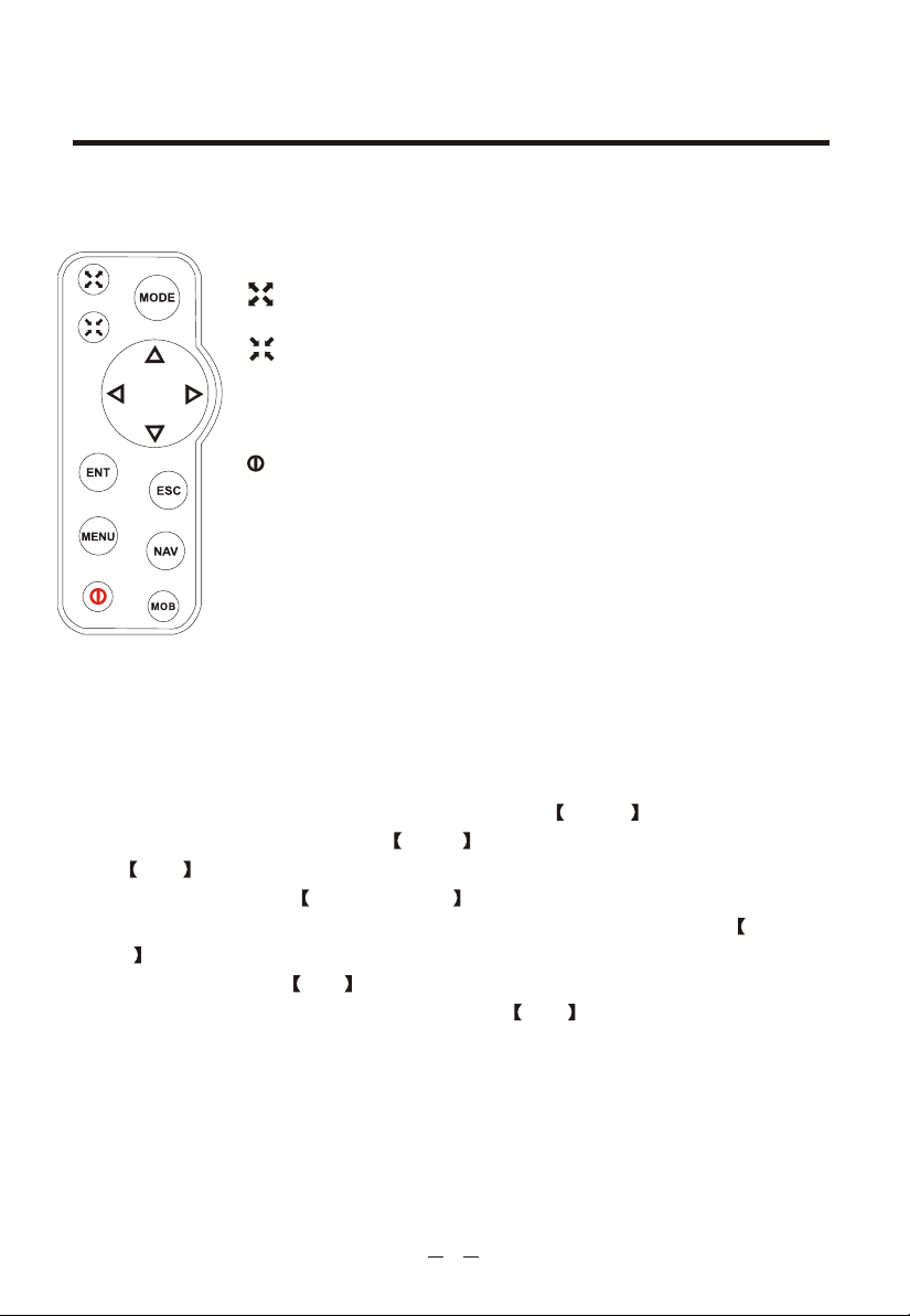
Figure1-1
1. Keypad instruction 1. Keypad instruction
Keypad instruction( Figure 1-1)
MENU: Pressing it displays the menu of the current page,
pressing twice enters the main-menu.
: Enlarges the scale of the maps and charts,16 grades
totally. Display the listed items of the page by revers e-scrolling.
: Reduces the scale of the maps and charts,16 grades totally.
Displays the listed items of the page by scrolling.
NAV: MOB navigation, cursor navigation, achieve way-point
navigation, route navigation, return voyage.
:Turn the power on/off, adjust the back light brightness and
the volume, display the battery capacity.
ESC: Withdraw from the optional operation, or display the
previous page in reverse-cycle order.
ENT: Confirms the input or data.
Arrow: Move the cursor or select the number or letter.
MODE: Display the four main screens circularly, turn over the
listed interfaces.
MOB: The MOB mark denotes man overboard position.
The basic input principles for the equipment : Press MENU key to enter the menu
setting accordingly, then press the Arrow keys to move the cursor to select items,
press ENT to enter.
the required state. Press up/down Arrow keys to select the letter or number.
The number contains from 0 to 9, the letter contains from A to Z. Press left/right
Arrow keys to move the cursor.
During the input, press ESC key at any time to cancel the current operation and
return to the previous menu or operation; Press ENT key to confirm the current
input, and continue to enter the next operation or menu. In relation to the similar
operations, this manual will not repeat again.
5
Page 8
2. BASIC OPERATION2. BASIC OPERATION
2.1 Main Screens
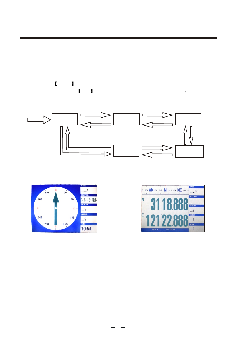
The five main screens are as following: Plotter screen, Navigation screen
(see Figure 2), Route screen, AIS Radar View and Position screen(see Figure 3).
Keep pressing arrow key displays accordingly the four main screens by a posit-
ive cycle, keep pressing exit key displays them by a reverse cycle
Power on
Plotter screen
Navigation
screen
Position screen
Route screen
AIS Radar View
Figure 2 Figure 3
6
Page 9
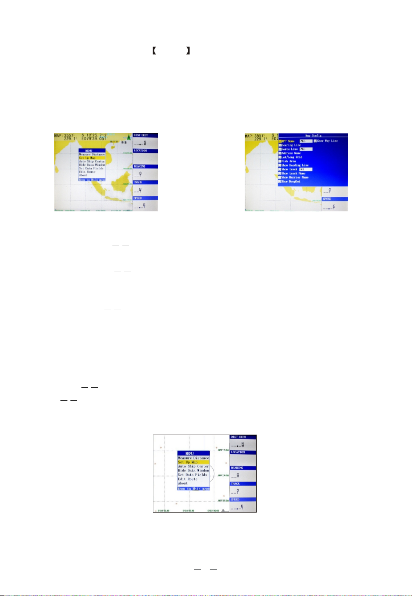
(1) Plotter screen : Pressing MENU key displays the following menu,
see
Figure 4), press [ENT] to enter sub-menu(see Figure 5).
Measure Distance ¯¯Measure the distance from own ship to the target.
Set Up Map ¯¯Hide or display the waypoint name, the direction, the route,
the place name, grid lines, fishing lines, the first flight line, the dynamic track,
history of the track, the name of obstacles, water depth, etc.. Figure 5
Figure 4 Figure 5
Show Ship Center The position of the vessel does not move during the
sailing, keep it centered and move the charts.
Auto Ship Center When the navigation of the vessel is beyond the plotter
screen, the vessel will be automatically centered.
Hide Data Window Hide the data field, enlarge the plotter screen.
Set Data Fields Change the items showed in the data field. May choose to
display the data including:
PDOP, Bearing, Start BRG, Steer, Cross Track, Destin-
ation Distance, Next Waypoint Distance, ETA Destination, ETA Next Waypoint, ETE
Destination, ETE Next Waypoint, Elevation, Location, Destination Location, Next
Location, Speed (SOG), Time, COG, Turn, Destination Waypoint, Next Waypoint,
Pointer, Fishing Area
Edit Route Establish the routes rapidly on the plotter screen.
About the version number, the contact information of the product and service,
and the serial number.
Figure 6
7
Page 10
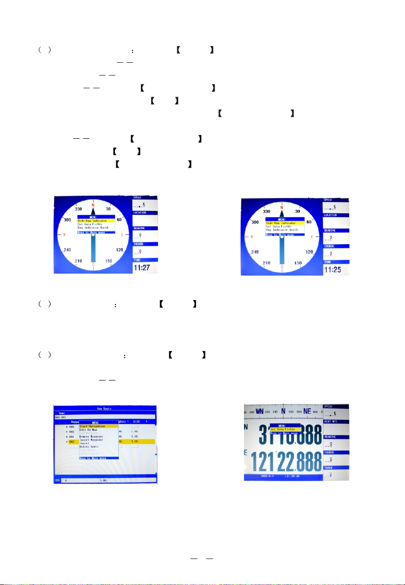
2 Navigation screen Pressing MENU key displays the following menu.
Hide Bug Indicator
Set Data Fields
Hides the markings of initial course.
Change the items showed in the data field . Same as above.
Heading up Press the up/ down Arrow keys to move the cursor to the "hea-
ding up" column, then press ENT key, the top of the compass should be the dir-
ection to the navigation of vessels. Press the left/ right Arrow keys to rotate the
direction of the compass. See Figure 7
North-up Press the up/down Arrow keys to move the cursor to the "north up"
column, then press ENT key, the top of the compass should be the direction of
the north. Press the left/ right Arrow keys to rotate the direction of the compass.
See Figure 8
Figure 7 Figure 8
3 Route screen Pressing MENU key displays the following menu.
Select the corresponding menu item to carry out the following operations: to start
navigation, map editing, add the waypoints, delete waypoints, insert the waypoint,
route reversal, remove the route, copy the route, reverse the track. See Figure 9
4 Position screen Pressing MENU key displays the following menu. See
Figure 10
Set Data Fields Change the items showed in the data field . Same as above.
Figure 10Figure 9
8
Page 11

2.2 Operation
2.2.1. Turning the power on/off, adjusting the brightness and the contrast
Power on :
Pressing and holding the Power key till it beeps turns the power on, the screen
displays pictures.
Power off
Pressing and holding the Power key till it beeps turns the power off, it displays
the countdown screen then disappears after 5 seconds.
Adjusting the brightness and contrast
Shortly pressing the Power key displays "brightness" and "contrast", press
up/down Arrow keys or the Power key to adjust brightness, use the
right/left Arrow keys to adjust the contrast. See Figure 11
2.2.2. Establish waypoints and position storage
Establish a new waypoint on plotter screen by cursor :
Press the MODE key to enter Plotter screen, press the Arrow keys to move
the cursor to the position which required to establish the waypoints, and press
ENT key, then press ENT key again, this equipment will automatically estab-
lish and number the new waypoint . See Figure 12
nput the longitude and latitude to establish a new waypoint
I
Press key MENU twice to enter the main menu, move the cursor to the "Point"
column. Press MENU key and move the cursor to the "New WPT" column,
then press ENT key. Displays the new waypoint screen, it's ready to edit the
waypoint. Move the cursor to the "name" column, press ENT and input the way-
point number or symbol, press the ENT key again to finish. Then move the cursor
to the "position" column,press ENT and input the latitude and longitude, press
ENT to finish.
Figure 11 Figure 12
9
Page 12

Then move the cursor to "OK" column, and press the ENT key to complete
the establishment of a new waypoint. See Figure 13 Position storage and the estab-
lishment of a new waypoint.
Establish a new waypoint by ship's position: get satellite fix, and
the ENT key on
hold either Plotter screen, Navigation screen or Positioning
After press
screen until a beep sound is heard. A new waypoint is established according to the
current ship's position.
2.2.3. Delete the waypoint
Press the MODE key to enter the Plotter screen, and move the cursor to the
waypoint required to be removed, then press the ENT key, it appears "Edit Way-
point screen". Move the cursor to "delete", press the ENT key to delete the way-
point. See Figure 14.
Figure 13
Figure 14
Delete the waypoint with the main menu
Press the MENU key twice to enter the main menu, move the cursor to the
"Point" , then move the cursor to "the waypoint required to be deleted", press
the MENU key, and the menu window pops up. Move the cursor to the "Delete"
column, and press the ENT key
to confirm.
Delete all the waypoints with the main menu
Press the MENU key twice to enter the main menu, move the cursor to the
"Point" column , press the MENU key and move the cursor to " ",
Delete All
press the ENT key , and then move the cursor to the "OK", press the ENT
key to delete all the waypoints.
Figure 15
10
Page 13

2.2.4. Single point navigation and cancel navigation
Single point navigation
Pressing the NAV key at any screen appears the navigation menu. Move the cur-
sor to the " " column and press ENT key to select the single point
navigation.If cursor navigation is required, move the cursor to "cursor navigation"
column and press the ENT key to select cursor navigation. See Figure 16.
Go To Point
Cancel navigation
Pressing the NAV key at any screen appears the navigation menu, select "Stop
Navigation" to cancel navigation operation.
2.2.5. Route setting and route navigation
New routes
1)Press the MENU key twice to enter the main menu, move the cursor to the
"Route" column and press the MENU key to enter the sub-menu, move the cursor
to "New Route" column and press the ENT key, displays the new route screen.
Press ENT and use Arrow keys to set the route name (numeric or alphanumeric),
press the ENT key to confirm the name, move the cursor to the "Waypoint" and
press the ENT key, use the cursor to select the desire waypoint and press
ENT to add it into the route, then press the MENU key to open the menu
window, move the cursor to "Edit on Map" column and press the ENT key, that
is, the establishment of new routes. See Figure 17
Figure 16 Figure 17
11
Page 14

2 ) Press the MODE key to enter the plotter screen, press the MENU key and
move the cursor to the " " column, then press the ENT key, the route
window pops up, move the cursor to "New Route" column, press the ENT key,
appears the new route screen. Pressing the MENU key pops up the menu window,
move the cursor to " " column, and press the ENT key, move the cu-
rsor to cover the waypoints on the charts, and press the ENT key, and then move
the cursor the cover the next waypoint, follow the above operations to establish the
route. See Figure 18.
3 ) Establish routes on the screen: Press the MODE key to enter the
screen, and set the route name, then press the ENT key, move the cursor to the
next column and press the ENT key , displays the list of the waypoints, move the
cursor to the waypoint and press the ENT key, then move the cursor again to the
next waypoint and follow the above operations. Press the MENU key, the menu
window pops up, move the cursor to the "map editor" column, press the ENT key
to complete the establishment of the route.
Edit Route
Edit on Map
Route Route
Delete the route
Press the MENU key twice to enter the main menu, move the cursor to the " Route" ,
then move the cursor to a certain route, press the MENU key and select "
Route
" column, press the ENT key and select "OK", again press the ENT key to
delete the route. See figure 19.
Delete
Figure 18 Figure 19
12
Page 15

route/reverse route navigation
Press the MODE key to enter the screen, then press MENU key and
move the cursor to the "Start Navigation" column (being implemented), or " "
column (in reverse order), and then to begin navigation. See Figure 20
Route
Invert
press ENT
2.2.6. The operation for track recording
This equipment adopts the new way for track recording, it provides a large storage
space for track recording, the simple and intuitive operation, and the strong editing
feature, the specific feature is as following:
39 storage tracks, can be set to display on/off respectively, segmentation edit,
save and copy, there are 4 kinds of lines and 8 colors to choose.
One real-time track record, with two kinds of recording methods, may regulate
the interval, pause etc. at any time during the process of recording.
A total of 40 track lines, 2100 track points for each track , can store 84,000
track points in total.
New track/Stop/Pause
Double-click the MENU key to enter the main menu, move the cursor to the
"Track" column, and then press the right Arrow keys to move the cursor to the
"New", click ENT key to start recording the track, see Figure 21. After the track
record begins, the "New" into "Stop"; the "Record" into "Pause".
If move the cursor to the "Pause" on the left and click ENT key, the "Pause" will
changes
be into "Record" , then track record will be paused, Click ENT key at
the "Record" , the "Record" will be to the "Pause" , then it will continue
to record the .
Note: The track would not be recorded during the period of the pause, there
would be blank displayed on the charts, without track connection.
track
changes changes
changed
Figure 20 Figure 21
13
Page 16

After the beginning of track record, even if it's under the pause state, move the
cursor to the "Stop", click ENT key to turn off the record. And will automatically
name the track record for the user to edit. At the beginning of track record, the
"scale ruler" on the chart screen will be a red background, otherwise be white.
Note: The status of starting, stopping or pausing the track record will be saved,
the orginal state before being shut down will be maintained.
Track record setting
Double-click the MENU key to enter the main menu, move the cursor to the
"Track" column, see Figure 22, the options for the track record method are as foll-
owing: "Mode" and "Interval". The "Mode" includes the two options: "Fill" and
"Wrap". The "Fill" modeis: When a track record is completed, the system will save
the current track and meanwhile start a new track record. The "Wrap" mode is:
When it reaches the 2100 track points for the current record, remove the track point
on the end of track line, and store the newest track point, make a cycle use of a
track's storage space.
Figure 22
Interval
The " " determines the span of the adjacent track points recorded, one is to
determine the span of track record by the "Time"; The other is to determine the
span of track record by the "Dist". Thus, the options for " " include:
the measurement of the record and the interval of the record. The measurement of
the record is , and the corresponding units of measurement are
hh:mm:ss
" " and "nm".
The "Time" mode for the track record is as following: it takes time as the mea-
sure unit for track record interval, and records 1 track point in a specific time int-
erval. The smallest time interval is 1 second, under the recording mode of time, the
track points which change less than 0.001 points at the latitude and longitude will
not be continuously recorded.
"Time" and "Dist"
14
Interval
Page 17

The "Dist" mode for the track record is as following: it takes length as the measure
unit for track record interval, and records 1 track point in a specified distance range.
The smallest distance interval is 0.01 nm (about 18 m).
Choosing a suitable interval value for the track record can make a full use of the
track storage space, e.g., if take 0.5 nm (about 900 m) as the record interval, for a
track record of 2100 track points, it can record at least nm miles of the routes; If
sail at the speed of 10Knots, you can record the track points for 100 hours.
Note The track recording method can be changed during the track record; The
original state before being shut down will be maintained.
Track editing
Double-click the MENU key to enter the main menu, move the cursor to the
"Track" column, and then press the right Arrow keys to move the cursor to the
saving or saved track Memory
" ", click ENT key, and the " " window pops up,
see Figure 22.
Figure 22
Selecting "Type" means to adopt a different way of drawing to display
the tracks on the chart screen, the line the following four kinds
types include
of line : dashed / thin solid line / thick solid line / point solid line. The
"color" selecting refers to use different colors to display the track on the
chart screen, a total of 8 kinds of colors to choose.
Note The track line named as " " or "New " is the tr-
Recording Record
ack line being recorded for real-time track points, can not be edited,
the track lines which have been saved can only be edited after the rec-
ord is "stop".
15
Page 18

Track display on/off
Double-click the MENU key to enter the main menu, move the cursor to the
"Track" column, and then press the right Arrow key to move the cursor to the
track need to be edited, press MENU key, Move the cursor to the " "
column and then press ENT key , this track will be displayed on the charts; Press
ENT key on the " " column, this track will not be displayed on the
charts. The " " and " " option are multiple choice, will not
appear at the same time.
Note whether or not to display the track also depends on the option of "Con-
trol the track display according to the scale", if out of the scale, the track
line will not be displayed. Please refer to the Display tracks by scale section.
Open Display Close Display
Close Display
it is
Open Display
Copy/Delete the track
Double-click the MENU key to enter the main menu, move the cursor to the
"Track" column, and then press the right Arrow key to move the cursor to the
track need to be edited, press MENU key, see Figure 23.
Figure 22
Move the cursor to "Copy" or "Delete" or "Delete all" and then press ENT key,
can respectively copy or delete this track line, or delete all the track lines.
Figure 23
Track back
Double-click the MENU key to enter the main menu, move the cursor to the
"Track" column on the left, and then press the Arrow keys to move the cursor to
the track need to be edited, press MENU key, the "Track editor " window pops
up, Or press the MENU key to enter the "Track menu", Move the cursor to the
"Track back" and press ENT key, then enter the track back navigation. The ship
will be firstly navigated to the nearest point from this track line by the navigator,
and then follow this route through "return the same way" navi-gation, with the na-
vigation data such as steering angle, drift angle, drift distance etc provided by the
navigator to sail along the track line.
16
Page 19

The other way to enter track back navigation is as following: Click the NAV key
at any screen, move the cursor to " " column and press ENT key,
see Figure 24. Press ENT key on the " " column, and then choose
a track line and press the ENT key to enter the track back navigation.
Navigate Track
Navigate Track
Display the track as per the scale
Press MENU key on the charts screen, and move the cursor to " ",
then click the ENT key.
At the left side of the " " option, if is selected, the track can be dis-
played on the charts, for the specific track to be displayed, it depends on whether
or not the track is set to be displayed on; If is selected, whether the track is set
to be displayed on or not, the tracks will not be displayed on the charts.
The scale option is at the right side of the " " option, only when the ch-
art is enlarged to be within the selected scale, the track lines set to be "Track dis-
play on" will be displayed on the chart screen. The "ALL" means under any scale
the track lines set to be "Track display on" will all be displayed on the chart screen.
To set track line to be "Track display on", please refer to Track Display On/Off
section.
Show Track
Show Track
Set Up Map
Delete all the tracks
Press MENU key twice to enter the main menu, move the cursor to the "Track"
column, and then move the cursor to "Track history", then press MENU key, the
menu window pops up, move the cursor to "delete all the history tracks" column,
press ENT key can clear all the tracks.
2.2.7. Emergency (MOB) navigation
In case of any emergency occurs at sea, press the NAV key. Move the cursor to
the "MOB" column and press ENT key; Or press and hold the NAV key, till
the "MOB" confirmation option pops up. Move the cursor to "Confirm" column,
press ENT key, the satellite navigation will in automatic navigation to the eme-
rgency point and also establish the waypoint. See Figure 25
Figure 25Figure 24
17
Page 20

3.THE MAIN MENU FUNTION3.THE MAIN MENU FUNTION
Pressing the MENU key twice at any of the main screens can enter the main
menu, move the cursor to a column, press the right Arrow key to enter that col-
umn for setting or adjusting.
GPS
The satellite distribution is on the left of the upper half screen, the longitude and
latitude of the current location, the year, the month, the day and the time on the
right. The lower half is about the satellite signal strength. The latitude and longit-
ude whose color turns into black color is the positioning latitude and longitude. See
Figure 26
Route
Enter the "Route" column and press the MENU key may establish a new route or
check, route navigation, delete a particular route or delete all, adding the track into
the route. See Figure 27
Figure 27Figure 26
Point
Entering the " " column can establish a new waypoint and make a list of the
existing waypoints. Move the cursor to the "Waypoint list", and then move to the
waypoint required, then press the MENU key can select the operation of "New
waypoint", "Delete waypoints" or "Delete all".
Point
18
Page 21

Barriers
Enter the " " column, two ways to establish the point.
1) Press the MENU key to select " ", press ENT key to enter the
New window, move the cursor to the "symbol" option the "Name"
column, pressing ENT key appears 99 kinds of symbols (see Figure 28), press the
Arrow keys to move the blue box onto the symbol selected, and press ENT
key, move the cursor to the "Location", input the latitude and longitude, move the
cursor to "OK", press ENT key. If need to , press the
MODE key to enter the charts, pressing the MENU key appears the menu wi-
ndow, move the cursor to " " column, pressing the ENT key appears
the map setting window, move the cursor to " " column, press
ENT key , and then press the ESC key.
2) To establish points on the chart: press the Arrow keys to move the
cursor to the position of establishing the , pressing ENT key appears the
" " window, pressing the MENU key appears the menu window,
New WPT
move the cursor to " " column (see Figure 29), pressing the ENT
key appears " " window, move the cursor to the "symbols" of the "Name"
column, pressing ENT key appears 99 kinds of symbols, and then press the
Arrow keys to move the blue box onto the symbol selected, and press ENT
key, move the cursor to the "OK" and press ENT key.
Barrier there is barrier
New Barr
Barrier beside
show barriers on the chart
Set Up Map
Show Barrier Name
barrier
barrier
Insert to Barri
View Barr
Figure 28 Figure 29
Enter the " " column, two ways to delete points.
1) pressing the MENU key appears the menu window, press the Arrow keys to
move the cursor to the "Delete" column or "Delete all" column, and then press the
ENT key.
2) To remove the points on the charts: move the cursor to the point
required to be removed on the chart, pressing ENT key appears the " "
window, move the cursor to the "Delete" and press ENT key.
Barrier there are barrier
barrier barrier
View Barr
19
Page 22

Alarm
Enter the "Alarm" column to review and set the alarm as following: point
alarm, Arrival alarm, alarm, alarm, alarm,
PDOP (accuracy)
Offset Anchor Drag Impact(Collision)
alarm. See Figure 30
Next WPT
Tide
Enter the "Tide" column, move the cursor respectively to "At" column, and press
the ENT key, the tides situation of the major ports along the coast on any parti-
cular date can be found. Move the cursor to the Tide screen, press the left/ right
Arrow keys, the time of the high/low tides on that current day and the tide height
can be found. The vertical axis is representative of the height of tides.See Figure 31
Figure 30 Figure 31
Unit
Enter the "Unit" column to set the distance and speed ( ),
the elevation unit, naming rules and magnetic declination.
Nautical, Statute and Metric
20
Page 23

Setup
Enter the "Setup" column to review and set the manner as following :
System Mode:
Data Source:
Speed Filter
set the filtering levels of the speed according to the needs, suggest that the larger
the winds and waves are, the higher the level is. The specific level can be set acc-
ording to the hull length and antenna height as well as the habits.
Time Zone: Enter the local time zone.
Rotate Map
that is, upper for the north, upper for the East, upper for the South, or upper for the
West.
Remain Space
waypoints, routes, and tracks.
Oil Used Rate
destination
Time Format: Set to display 24-hour or 12 hours. see Figure 32
Marine or Simulator
Inside, SD or Auto
: (continuously adjustable from 0 to 99 levels): The users may
user's
: Users may set up the charts display setting according to the needs,
: Indicate the remaining memory space after the storage of the
: Enter the fuel consumption to estimate the fuel needed to reach the
In/Out
Output NMEA0183, input and output the waypoints, the routes, and the tracks. At the
same time, the user may set it to be the different baud rate. See Figure 33
Figure 32 Figure 33
Press the MENU key to clear all the stored data and save all the data.
21
Page 24

4.THE AIS FUNTION4.THE AIS FUNTION
4.1 Start AIS function
Enter the "Main Menu", select the "In/Out" column, at the " " column
select "Connect AIS ", and then move the cursor to the "OK", press the
ENT key to connect AIS equipment. See Figure 34
Device
4.2 Vessels list
Enter the "Main Menu", and select the "AIS" to check all the AIS vessels received
by the current AIS equipment. See Figure 35
Figure 34 Figure 35
4.3 The collision alarm
Enter the "Main Menu", and select the "Alarm", and then select the scope of the
collision alarm according to the time and distance. See Figure 36
There are
live audio broadcast and also the capability to broadcast the distance, it has to
be indicated in the purchasing order for this optional function if needed.
an optional feature comes with the collision alarm as following: the
Data In/Out
Figure 36
22
Page 25

4.4 Own ship's information
Enter the "vessels list", and press the MENU key, and then select the "
Info
" to check all the information of own ship, see Figure 37.
The own ship's information is also displayed on the upper right of the radar screen,
see Figure 42.
For the own ship's information, such as MMSI, the antenna height, the location,
draught, etc., please consult the suppliers. Before inputting the information, the
system may not be able to work or can only receive the information.
Figure 37 Figure 42
Own Ship
4.5 Chart Screen
Users can check all AIS vessels being received in real-time on the chart screen, as well
as the specific position and track of the own ship on the charts. See Figure 38
The track length of AIS vessels depends on the memory space, generally
not less than 20 track points.
equipment
Figure 38
23
Page 26

4.6 View AIS vessels' information on chart screen
There're two ways to view AIS vessels' information: one is to move the cursor to
select AIS vessel on the charts screen, and press the ENT key. See Figure 39
The other is to select the AIS vessel from the AIS vessels list, and press the ENT
key. See Figure 40
Figure 39 Figure 40
4.7 Check all AIS ships within the scope of Radar
Displays all AIS ships within the current scope of the Radar, the current location
of the own ship is at the center of the map, appearing as a white hollow triangle,
and the vertex angle of the triangle stands for the current direction of the own ship,
the blue hollow triangle stands for the vessels of CLASS B, the green hollow tria-
ngle stands for CLASS A vessels, the green hollow square stands for BASE STAT-
ION, and the vertex angle of the triangle stands for the direction of the vessel, such
as round, and the circle stands for no direction.
The collision alarm setting and the current scope of radar can be displayed on the
upper left corner of the radar, and the scope be adjusted by pressing the key
and key.
The message display frame on the upper right corner of the radar displays the foll-
owing information: the own ship's position, the current time, the current speed /
direction of the own ship.
(AIS screen)
24
Page 27

4.8 Emergency alarm
The information of the emergency alarm received is displayed on the bottom right
corner. The emergency alarm is always available and can not be deleted, if the em-
ergency alarm information is not read, after exiting the alarm menu, the "emergency
alarm" window will pop up a little latter. The warning ship displayed on the Radar
will be yellow and flashing. See Figure 42
Figure 42
The relevant data (including the time, place, the relevant ship s information,
'
etc.) will also be saved by the display terminals, it can be the basis of an-
alysis in the event of any accident.
4.9 Entry/Departure setting
The Entry/Departure setting is for temporarily shut down or restart the co-
llision alarm, when entering the port the collision alarm will be temporarily
closed, when leaving the port the collision alarm will be opened. There are
two ways for Entry/Departure setting
1) Press the MENU key at the Radar window, and select "" or
Out Port
"". See figure 43
2) Press the NAV key at any window, and select "" or "".
In Port Out Port
In Port
See figure 44
Figure 43 Figure 44
25
Page 28

Navigation Terms
Bearing(BRG) The compass direction from your current location to a destination.
Start BRG The desired course between the active from and to waypoints.
Distance (Dist) The distance from current location to a destination.
Dist to Destination The distance from current location to a Goto destination, or
the final waypoint in a route.
Dist to Next The distance from current location to a Goto destination, or the
next waypoint in a route.
PDOP Dilution of Precision reflects the quality of the GPS signals and satellite
geometry.
Elevation Height above mean sea level(MSL).
ETA(Estimate Time of Arrival) The estimated time you will reach your destin-
ation waypoint, based on current speed and track.
ETA at Destination The estimated time you will reach a Goto destination or the
final waypoint in a route.
ETA at Next The estimated time you will reach a Goto destination or the next
waypoint in a route.
Cross Track The distance you are off a desired course in either direction, left
or right.
Pointer an arrow pointing to you destination.
Speed The cureent velocity at which you are travelling, relative to a ground po-
sition. Also referred to as ground speed.
COG The direction of movement relative to a ground position, Also referred to
ground track.
as
Turn The angle difference between the bearing to your destination and your
current track. L indicates you should turn left; R indicates you should turn
right. Waypoint Destination The final waypoint in the route, or the destination
waypoint.
Waypoint Destination The final waypoint in the route. or the destination way-
point.
Waypoint Next The next waypoint in the route.
26
Page 29

5.Main Performance and Specifications5.Main Performance and Specifications
5.1 Performance and characteristics
5.1.1 The GPS function
1) Satellite receiver type: 16 discrete channels receiver, differential signals can be
received
2) Positioning accuracy: 10 meters (CEP) the accuracy of 3 meters (CEP)
3) Speed accuracy: 0.1 Knots (RMS)
4) Positioning time: 15 seconds for warm start, 45 seconds for cold start
5) Update rate for positioning data: once per second
5.1.2 Navigation
1) Up to 18,000 waypoints, including the optional logo, or as geographic information.
2) Up to 50 routes: 50 (300 waypoints for each route)
3) Track Points: 40 Track points, including 1 real-time track record, 39 history track
records, 2100 points for each track, 84,000 points in total, the information of each
point including the time, location and direction
4) 40 track point lines (2100 points for each)
5) Up to 99 kinds of signs for various objects
5.1.3. Data Interface
RS-232 serial port: NMEA2.0 and the data exchange with other equipment.
USB1.0 Slave: To upgrade the software and map data.
27
Page 30

5.1.4. Equipment Parameters
1) The shell: ABS all-sealed and waterproof design, metal stents.
2) Size:
KP-823 262 172 65 mm
KP-622/623 205 125 55 mm
3) Weight:
KP-622/623: 0.6 kgs approx.
KP-823: 0.8 kgs approx.
4) Display
KP-823 8" (162mm 121.5mm) 640 480 dot-matrix, TFT color LCD display
KP-622 5.7" (119mm 97mm) 320 240 dot-matrix 8 grades of gray liquid crys-
tal display.
KP-623 5.7" (119mm 97mm) 640 480 dot-matrix, TFT color LCD display
5) Temperature: -30 to 65 (working temperature), -35 to 75 (Storage
tempe rature)
6) Power Supply :10-38V DC, about 3W for power, with protection.
5.1.5. Configuration
Active GPS Antenna with 10m cable (KA-08) : 1 pc.
1)
Display Mounting : 1 set
2)
3) 8-core data and power cables: 1 pc., see figure
Operator Manual : 1 copy
4)
5) 1A Fuse: 2 pcs.
46
28
Page 31

5.1.6 Installation: (see Figure 45)
Figure 45-a Desktop installation
Figure 45-b installationPanel
29
Figure 45-c Ceiling installation
Page 32

(+)
(+)
(+)
Power
10 38V DC
() (+)
Orange
Yellow
Black
Red
PIN 8 RS 232 RXD
PIN 6 Power +
PIN 7 RS 232 TXD
PIN 1 Power
6
5
7
8
4
1
3
2
Equipment
NMEA 0183
TXD
RXD
()
Brown
Green
Blue
PIN 3 USB+
PIN 5 RTCM RXD or other
PIN 4 USB
AIS
RTCM
DGPS
TXD
()
Wirle
PIN 2 Sound output
PC
USB
()
USB
USB+
1W
8
Figure 46 8-core electrical cable connection diagram
30
Page 33

 Loading...