

Onwa KF-1067 Owner's Manual

˵Ã÷Êé
˵Ã÷Êé
MODEL KF-667MODEL KF-667
OPERATOR`S MANUAL
COLOR VIDEO SOUNDER
KF-667KF-667
SAFETY INSTRUCTIONSSAFETY INSTRUCTIONS
WARNINGWARNING
Immediately turn off the power at the
switchboard if water leaks into the
equipment or something is dropped in
the equipment.
Continued use of the equipment can cause
fire or electrical shock. Contact a ONWA
agent for service.
Do not disassemble or modify the
equipment.
Fire, electrical shock or serious injury can
result.
Do not place liquid-filled containers on
the top of the equipment.
Fire or electrical shock can result if a liquid
spills into the equipment.
Immediately turn off the power at the
switchboard if the equipment is emitting
smoke or fire.
Continued use of the equipment can cause
fire or electrical shock. Contact a ONWA
agent for service.
Keep heater away from equipment.
A heater can melt the equipment’s power
cord, which can cause fire or electrical
shock.
Use the proper fuse.
Fuse rating is shown on the equipment.
Use of a wrong fuse can result in damage
to the equipment.
WARNINGWARNING
WARNINGWARNING
ELECTRICAL SHOCK HAZARD
Do not open the equipment.
Only qualified personnel should work
inside the equipment.
Make sure no rain or water splash leaks
into the equipment.
Fire or electrical shock can result if water
leaks in the equipment.

INTRODUCTION
PRINCIPLE OF OPERATION
SYSTEM CONFIGURATION
1. CONTROLS, INDICATIONS
1.1 Control Description
1.2 Indications
2. BASIC OPERATION
2.1 Turning the Power On/Off
2.2 Adjusting Brilliance
2.3 Display mode Selection, Description
2.4 Adjusting Gain
2.5 Automatic Operation
2.6 Selecting Picture Advance Speed
2.7 Display Range selection
2.8 Erasing Weak Echoes
2.9 Measuring Depth to a Fish School
2.10 A-scope Display
2.11 Menu Operation
2.12 Suppressing interference
2.13 Suppressing Low Level Noise
2.14 Selecting Background
and Echo Colors
2-1
2-1
2-1
2-4
2-4
2-5
2-6
2-7
2-7
2-8
2-11
2-11
2-12
2.15 Alarms
2.16 White Marker
3. INTERPRETING THE DISPLAY
3.1 Zero Line
3.2 Fish School Echoes
3.3 Bottom Echo
3.4 Surface Noise/Aeration
4. MAINTENANCE, TROUBLESHOOTING
4.1 Maintenance
4.2 Basic Troubleshooting
4.3 Transducer Check
4.4 Water Temperature
Sensor (option) Check
MENU TREE
SPECIFICATIONS
3-1
3-1
3-1
3-1
3-2
4-1
4-1
4-3
4-4
4-4
A-1
SP-1
INDEX
1-3
1-1
1-1
2-1
2-5
2-14
TABLE OF CONTENTS
2-12
Index-1

INTRODUCTION
Congratulations on your choice of the ONWA KF-667 Color Video Sounder. We are
confident that you will enjoy many years of operation with this fine piece of equipment.
The KF-667 is just one of the many ONWA developments in the field of echo sounding. The
compact, lightweight but rugged unit is easy to install and operate and is suitable for both fresh
and saltwater applications.
This unit is designed and constructed to withstand the rigors of the marine environment.
However, to obtain optimum performance from this unit, you should carefully read and follow the
recommended procedures for operation and maintenance. No machine can perform to the
utmost of its ability unless it is installed, operated and maintained properly
We would appreciate feedback from you, the end-user,about whether we are achieving our
purposes.
Thank you for considering and purchasing ONWA equipment.
Features
The KF-667 dual-frequency(50KHz and 200KHz)color video sounder has a large variety of
functions, all contained in a splash-proof rugged plastic case that is compact to fit small boats.
The principal features of the KF-667 are
User-friendly design for simplified operation.
A wide variety of display modes: bottom-lock expansion, marker zoom and unique bottom
zoom displays.
Potent 300 W transceiver.
8-color presentation(including background) on a 5.6 diagonal TFT LCD, providing vivid
presentation of underwater conditions.
AUTO function permits unattended range and gain setting operations. The range scale and
gain change automatically so that the bottom is displayed in reddish brown or red on the
lower half of the screen.
A-scope display gives excellent bottom fish discrimination, vital for bottom trawler
and lobster/crab potter.
Digital and analog displays of navigational data.

Alarms: fish, bottom, water temperature (requires appropriate sensor).
Six pulse lengths for excellent performance on both shallow and deep ranges.
Universal 12-24 VDC power supply drawing 30 W of power at maximum.
Water temperature sensor optionally available.
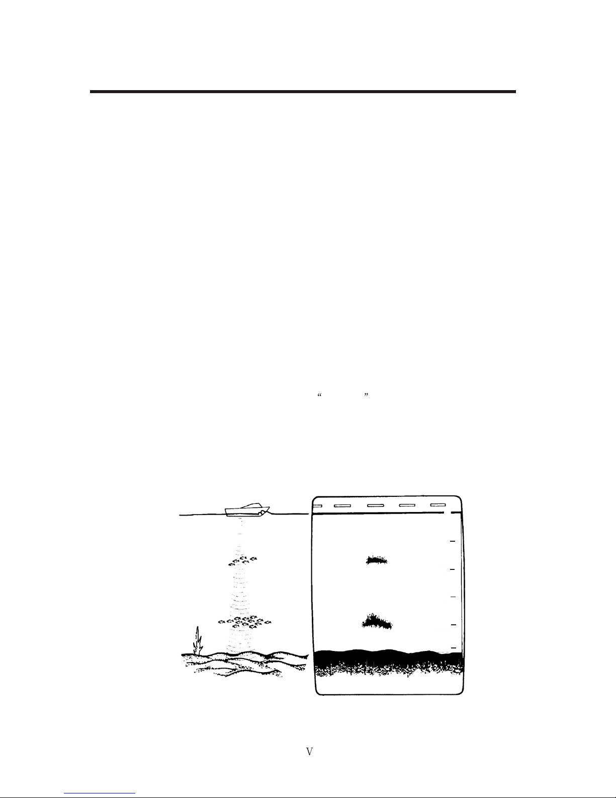
PRINCIPLE OF OPERATION
This Color Video Sounder determines the distance between its transducer and underwater
objects such as fish, lake bottom or seabed and displays the results on a 5.6-inch color screen.
It does this by utilizing the fact that an ultrasonic wave transmitted through water travels at a
nearly constant speed of 4800 feet (1500 meters) per second. When a sound wave strikes an
underwater object such as fish or sea bottom, part of the sound wave is reflected back toward
the source. Thus by calculating the time difference between the transmission of a sound wave
and the reception of the reflected sound wave, the depth to the object can be determined. In a
sense an echo sounder can be thought of as being an extremely sophisticated and quick timer,
since it is capable of resolving time differences shorter than one thousandth of a second.
The entire process begins in the display unit. Transmitter power is sent to the transducer as a
short pulse of electrical energy. The electrical signal produced by the transmitter is converted into
an ultrasonic signal by the transducer and transmitted into the water. Any reflected signals from
intervening objects (such as a fish school) are received by the transducer and converted back
into an electrical signal. It is then amplified in the amplifier section, and finally, displayed on the
screen.
The picture displayed by the Color Video Sounder is made up of a series of vertical scan lines,
one for each transmission, Each line represents a snapshot of what has occurred beneath the
boat. The series of snapshots are accumulated side by side across the screen, and the resulting
contours of the bottom and fish between the bottom and surface are displayed. The amount of
history of objects that have passed beneath the boat over a series of transmission varies from
less than a minute to a few minutes, depending on how you adjust the unit.
0
50
100
150
200
250
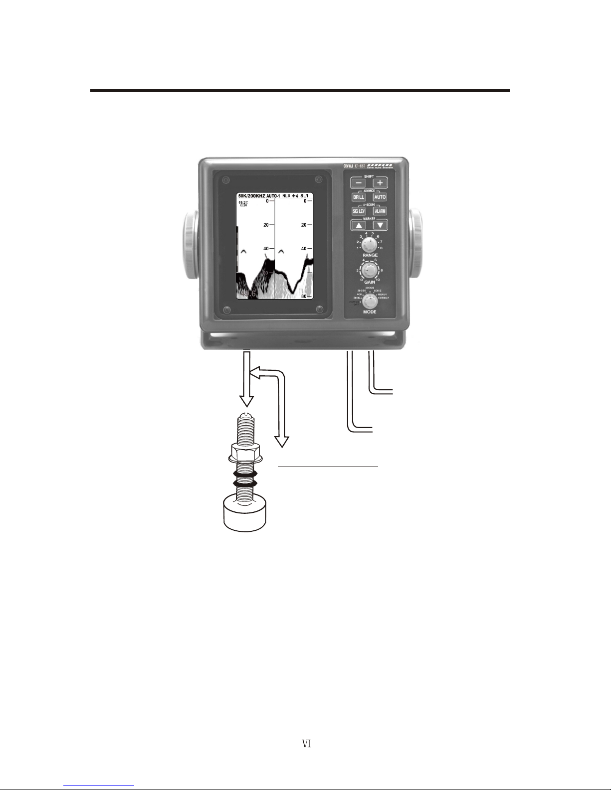
SYSTEM CONFIGURATION
DISPLAY UNIT
KF-667
Ship’s mains
12-24 VDC
External equipment
(GPS navigator, etc.)
Temperature sensor (option)
TRANSDUCER
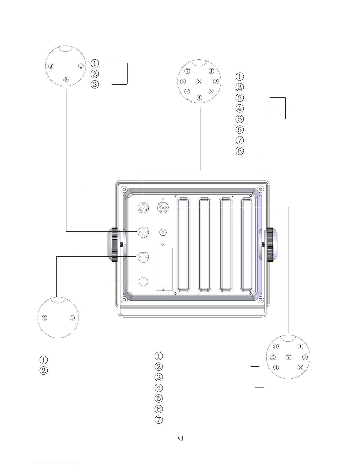
NMEA-0183 input(RX+)
NMEA-0183 input(RX )
NMEA-0183 output(TX+)
NMEA-0183 output(TX )
GND
3.3V
NC
Temp GND
Temp in
TX
GND TD
TX
NC
NC
GND
TD/Temp
I/O
Fuse(3A)
TX
TX
GND
Power
DC12-24V
-VE
Transducer
1. CONTROLS, INDICATIONS
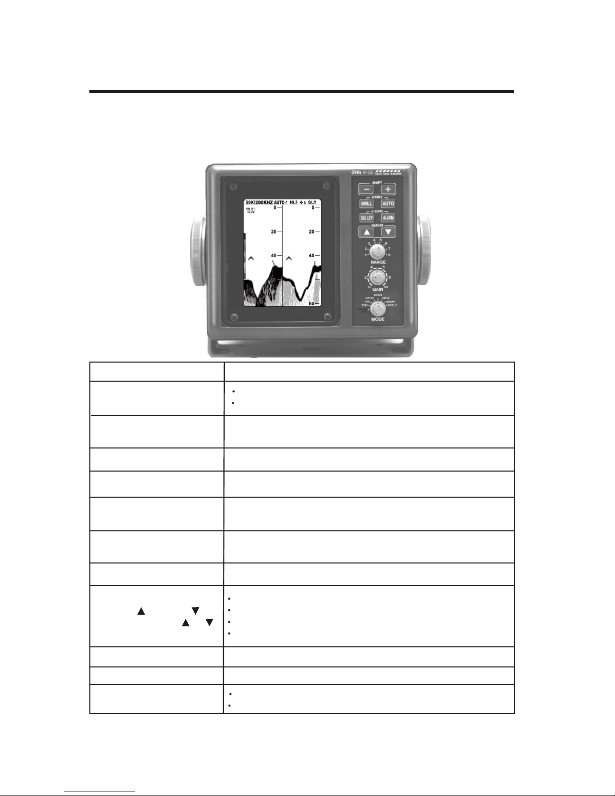
1.1 Control Description
The equipment is so designed that even a first time user can quickly become acquainted with the
operating procedure. Operation of each control or key is acknowledged by an alphanumeric
message or symbol indication on the screen.
Control Function
SHIFT-,SHIFT+ Change display start depth.
(Appears in text as [-],[+].) Select options on menus.
BRILL Adjusts brilliance of display.
AUTO Turns the automatic sounder adjustment feature on/off.
ADVANCE (BRILL+AUTO) Pressing the BRILL and AUTO keys together
selects display advancement speed.
SIG LEV Eliminates low intensity echoes (up to light-blue echoes) in
two steps.
ALARM Open/closes the alarm menu.
A-SCOPE Pressing the SIG LEV and ALARM keys together displays the
(SIG LEV+ALARM) A-scope display at the right 1/4 of the screen.
MARKER ,MARKER
(Appears in text as[ ]or[ ])
Shift the Variable Range Marker (VRM).
Set alarm zone.
Select menu items.
Set white marker.
RANGE Sets the basic range of the display.
GAIN Adjusts receiver sensitivity.
MODE Turns unit on/off
Selects display mode.
1-1
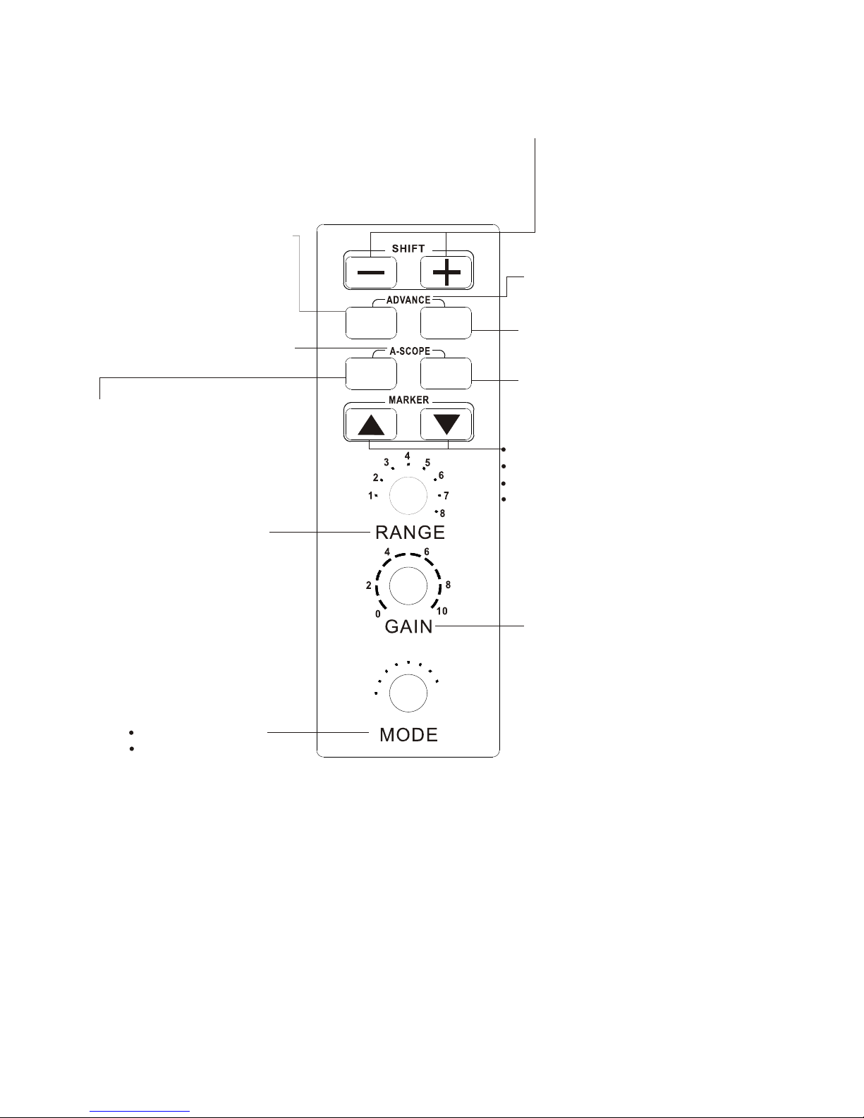
50K
POWER
OFF
200K
200/50
200K/Z
MENU1
MENU2
50K/Z
BRILL
SIG LEV
ALARM
AUTO
Change display start depth.
Select options on menus.
Turns the automatic sounder
adjustment feature on/off.
Adjusts brilliance of display.
Pressing the SIG LEV +
ALARM keys together.
Displays the A-scope display
at the right 1/4 of the screen.
Pressing the BRILL + AUTO
keys together. Selects display
advancement speed.
Open/closes the alarm menu.
Eliminates low intensity echoes
(up to light-blue echoes)
in two steps.
Shift the Variable Range Marker (VRM).
Set alarm zone.
Select menu items.
Set white marker.
Sets the basic range
of the display.
Adjusts receiver sensitivity.
Turns unit on/off
Selects display mode
1-2
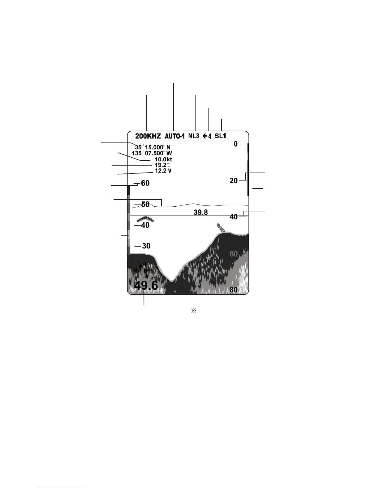
1.2 Indications
Auto Mode
Noise Limiter
Picture Advance Speed
Signal Level
Range scale
Alarm zone
marker
Variable range
marker(green)
w/depth readout
All indications and
markers are displayed
in white unless
noted otherwise.
Depth Requires external equipment.
Water
temperature
Water temperature
scale*
Water temperature
marker*(Color
changes with
HUE setting.)
Color bar
Mode
Nav data*
Voltage
Speed*
1-3
 Loading...