

Page 1
HOBO® ZW Series Wireless Network Quick Start Guide
13542-D MAN-ZW-QSG
This guide explains how to set up a HOBO ZW Series Wireless Network, which consists of a receiver, router nodes, and end-point data
nodes. The receiver is the central data collection hub that receives data from the router nodes and data nodes in the network. Router
nodes can either be standalone routers (no data logging capability) or data nodes doubling as routers (operating in dual mode: data
logging plus routing). End-point data nodes record data only (no routing capability). Follow the steps in this guide to set up these devices.
1
Survey the site and mark the
measurement points
Walk through your site to map out the measurement points,
which are the locations where you want to record sensor data.
This will determine where you need to place either router
nodes operating in dual mode or end-point data nodes. Note
that the real-time communication range possible between
nodes will depend on the obstructions in the path. You may
need to add more router nodes in the path to help data from
the measurement points reach the receiver or another active
router node. Every data node and router comes with a
mounting bracket. The mounting bracket allows you to adjust
the node orientation against the mounting surface so that it
gets better signal reception. For details on choosing the best
location for nodes, refer to the HOBO Data Node Deployment
Guide at http://www.onsetcomp.com/indoor-wireless-hobodata-nodes.
2
Identify power outlets for router nodes
Router nodes require AC power. Locate available outlets in your
site that can be used to provide AC power to the router nodes,
which may be necessary for strengthening the communication
within the network. The more router nodes you use, the more
robust the network is.
3
Start HOBOnode Manager
HOBOware® Pro 3.0 or higher is required for a ZW Series
Wireless Network. Install the software now if you have not
already done so.
1. Open HOBOware. From the Device menu, select Manage
HOBO Data Node Network.
2. Click Yes to enable data node capability in HOBOware.
4
Connect the receiver to the computer
1. Connect the power adapter to the receiver and plug it
into a wall outlet.
2. Insert three AAA batteries into the receiver for backup
power.
3. Connect the small end of the USB cable to the
communication port on the receiver. Plug the large end
into the USB port on the computer running HOBOnode
Manager. Note: The computer used to set up the
network must be the same one used to offload data from
the receiver at the site.
IMPORTANT: The receiver requires continuous power from
the computer to communicate with the other devices in the
network. Do not plug the receiver into a USB port that may
be shut down due to the power settings on the computer.
Disable any power saving options, such as Turn Off Hard
Disks, Hibernation, or Shut Down, on the computer. If you
connect the receiver to a USB port on your computer
monitor, do not enable any energy savings options on the
monitor.
4. The red and green LEDs blink continuously and the
receiver is displayed in the device table in HOBOnode
Manager with a status of CONNECTED as shown below.
(If the receiver does not appear in the device table, make
sure the USB cable is completely plugged in at both ends
or try unplugging the receiver and plugging it back in.)
A message also appears indicating a new receiver has
been detected and asking if you would like to begin
forming a network. Click Form Network Now. The
receiver is now in Form Network mode with both LEDs
staying continuously lit and the Forming Network
progress indicator appearing in HOBOnode Manager.
5
Build a backbone of router nodes
Build a backbone of AC-powered router nodes (dedicated or
dual mode) before adding any battery-powered data nodes to
the network. Start with the router node closest to the receiver
and move steadily to the farthest point, adding one node at a
time and ensuring it is ACTIVE on the network before you
proceed to the next node as described in the following steps.
Note: Leave the logging and connection intervals on the nodes
at the default of 1 minute and 10 minutes respectively until you
have built the complete network. Do not permanently mount a
node until you are sure it is being recognized on the network.
To add a router node to the network:
1. The Forming Network progress indicator should still be
visible in HOBOnode Manager. If it is not, then click the
Form Network button at the bottom of the HOBOnode
Manager window.
2. If this router node will also be recording data, connect
any external sensors.
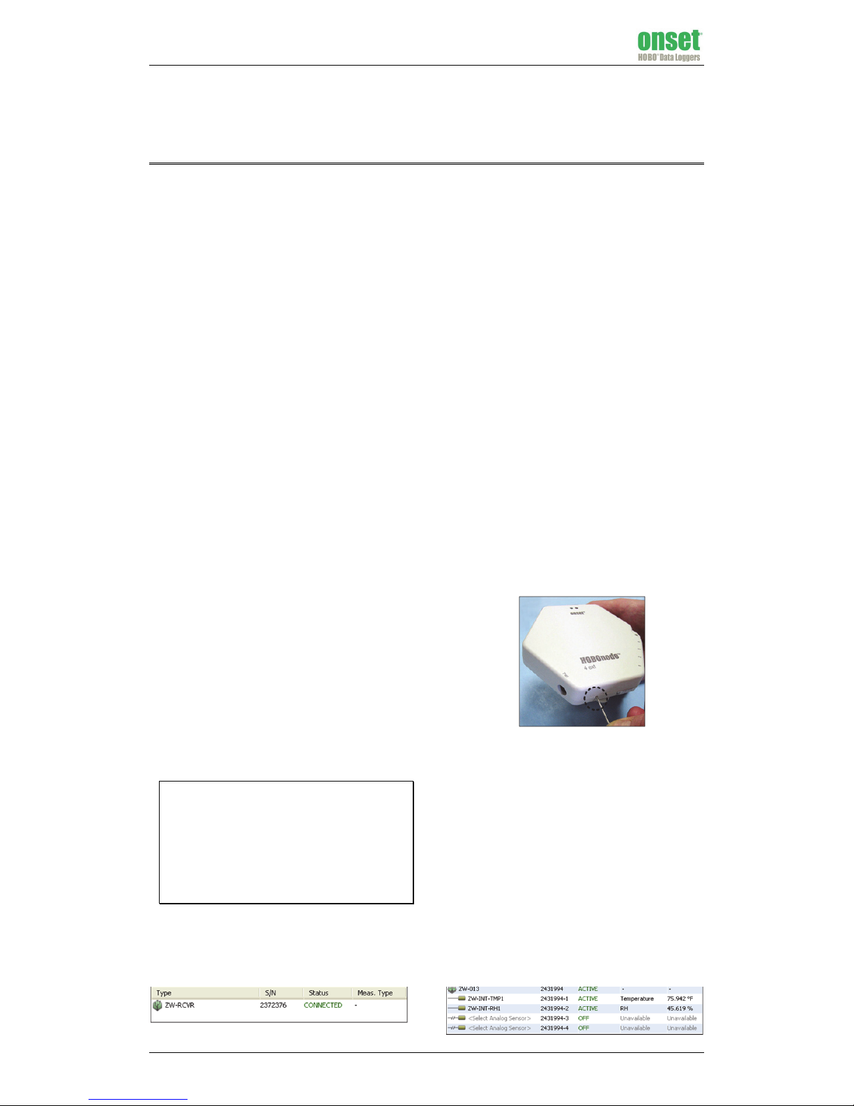
3. Plug in the AC adapter to power the node.With a wire
paper clip, press and hold the reset button located inside
the small hole at the bottom of the case for 5 seconds as
shown below. This will erase any previous network
information stored in the node. The red LED will blink
multiple times, then stop blinking, and then both LEDs
will be lit briefly.
4. Disconnect any power to the node (remove any batteries
and unplug the AC adapter). Wait for one minute, then
plug in the AC adapter to power the node again. Do not
install the batteries.
5. Using the paper clip again, press the reset button once (a
quick 1-second push) to put the node in “Form network
mode.” The green and red LEDs will alternate blinking.
• If the node finds a communication path to the receiver
within a minute, the alternate blinking will stop and
the green LED will blink. The node will display as
ACTIVE in the device table in HOBOnode Manager as
shown below. After a few seconds, both LEDs will light
and remain on while network formation continues. You
can now add backup batteries to the node and mount
it with the mounting bracket. Also consider labeling
the node in HOBOnode Manager and writing the same
label on the node sticker (see “Label nodes” on the
reverse side for more details).
www.GlobalTestSupply.com
Find Quality Products Online at: sales@GlobalTestSupply.com
Page 2
© 2010–2012 Onset Computer Corporation. All rights reserved. Onset, HOBO, and HOBOware are
trademarks or registered trademarks of Onset Computer Corporation. All other trademarks are the
property of their respective companies.
13542-D MAN-ZW-QSG
• If the node is not able to join the network, it will stop
the alternate blinking pattern after a minute and then
start blinking red. Move it to another location or adjust
the orientation of the node against the mounting
surface and repeat step 5 again.
• If the alternate blinking pattern lasts for more than 2
minutes, try resetting the node again (steps 3 and 4)
and then putting it back in Form Network mode (step 5).
6. Repeat steps 2 through 5 until you have placed all router
nodes one at a time, from the closest to the receiver to
the farthest. Before you proceed to the each new node,
identify which existing active node will provide a
communication path from the new node back to the
receiver. Refer to the Signal Attenuation chart in the
HOBO Data Node Deployment Guide to understand the
impact of the obstructions in the path between nodes.
6
Add end-point data nodes
Once all the router nodes are active, you can add end-point,
battery-powered data nodes. Before you deploy an end-point
data node, identify the nearest ACTIVE router node(s) that will
provide connectivity to the receiver. If more than one router
can provide connectivity, then this path redundancy will
improve the self-healing property and robustness of the
network.
1. Make sure the receiver is still in “Form Network” mode.
Click the Form Network button in HOBOnode Manager if
it is not.
2. Connect any external sensors to the data node if
necessary.
3. Add batteries to the node. With a wire paper clip, press
and hold the reset button for 5 seconds to erase any
previous network information that the node may have
been saving. The red LED will blink multiple times and
then stop blinking.
4. Disconnect any power to the node (remove any batteries
and unplug the AC adapter). Wait for one minute, then
install the batteries to power the node again. Do not plug
in the AC adapter.
5. Using the paper clip again, press the reset button once (a
quick 1-second push) to put the node in “Form network
mode.” The green and red LEDs will alternate blinking.
• If the node finds a communication path to the receiver
within a minute, the alternate blinking will stop and
the green LED will blink. The node will display as
ACTIVE in the device table in HOBOnode Manager.
Now you may mount the node with the mounting
bracket. Also consider labeling the node in HOBOnode
Manager and writing the same label on the node
sticker (see “Label nodes” in the next section for more
details).
• If the node is not able to join the network, it will stop
the alternate blinking pattern after a minute and then
start blinking red. Move it to another location and
repeat step 5 again.
• If the alternate blinking pattern lasts for more than 2
minutes, try resetting the node again (steps 3 and 4)
and then putting it back in Form Network mode (step 5).
6. Repeat steps 2 through 4 until you have placed all data
nodes.
7. Once all devices have joined the network and appear in
the device table, click the X in the Form Network
Progress indicator to exit Form Network mode.
7
Customize the network with
HOBOnode Manager
Use HOBOnode Manager to customize the network to work for
your site.
Configure external sensors
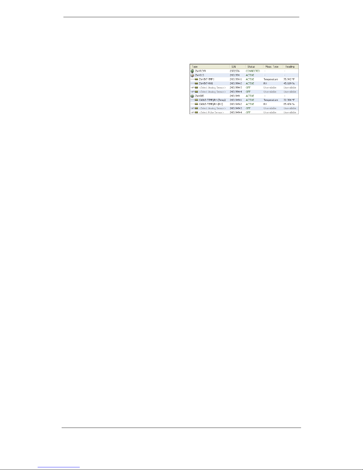
The device table in HOBOnode Manager lists all nodes that
joined the network. Current readings for internal sensors and
any external Temp/RH sensors are automatically displayed in
the table with an ACTIVE status. All additional sensor channels
are disabled by default and listed as OFF in the Status column
as shown below.
If you are using any external sensors other than the external
Temp/RH, you must configure the sensors in HOBOnode
Manager to record measurements.
1. Double-click the row in the table for the sensor you wish
to configure.
2. In the Configure Sensor window, select the appropriate
Sensor Type from the drop-down list. Add a label if
desired.
3. Click OK. The status for that sensor will change to ACTIVE.
If no data or incorrect measurements appear for an external
sensor, make sure the sensor has been configured as described
above and the correct sensor type was selected.
Plot the measurements
Click the checkbox in the Plot column in the device table for any
nodes/sensors you wish to plot (up to 20 maximum). It may
take a few minutes for data to start appearing in the plot.
Adjust logging and connection intervals
By default, data nodes will record measurements once every
minute and send data to the receiver every two minutes. To
change these logging and connection intervals for a device,
double-click that device in the table. Change the intervals and
click OK. You can also change the default intervals in the
Preferences (click the Actions button in HOBOnode Manager
and select Edit Data Node Preferences).
Label nodes
It is helpful to label each node in HOBOnode Manager as you
deploy it and write the same label on the node sticker (included
in the data node or router packaging). Double-click the <Enter
label here> field in the device table in HOBOnode Manager to
add a label to a node. Then, write the same name on the sticker
and affix it to the node.
Remove nodes
To remove a node from the network, double-click the node in
the device table in HOBOnode Manager and then click the
Remove Node button. Unplug the AC adapter if connected and
remove any batteries.
Additional resources
For additional guidelines on deploying the network, including
information about using brackets for spatial orientation of the
nodes and details on the node LEDs, refer to the HOBO Data
Node Deployment Guide available on onsetcomp.com. A list of
frequently asked questions about the ZW wireless system is
also available on onsetcomp.com
Refer to the help system in HOBOware or the HOBOware User’s
Guide for additional details on working with HOBOnode
Manager and the devices in the network, including setting
alarms, setting up a network map, creating groups, exporting
data, and much more.
www.GlobalTestSupply.com
Find Quality Products Online at: sales@GlobalTestSupply.com
 Loading...