

Page 1
Test Equipment Depot - 800.517.8431 - 99 Washington Street Melrose, MA 02176 - TestEquipmentDepot.com
Silicon Pyranometer Smart Sensor (Part # S-LIB-M003)
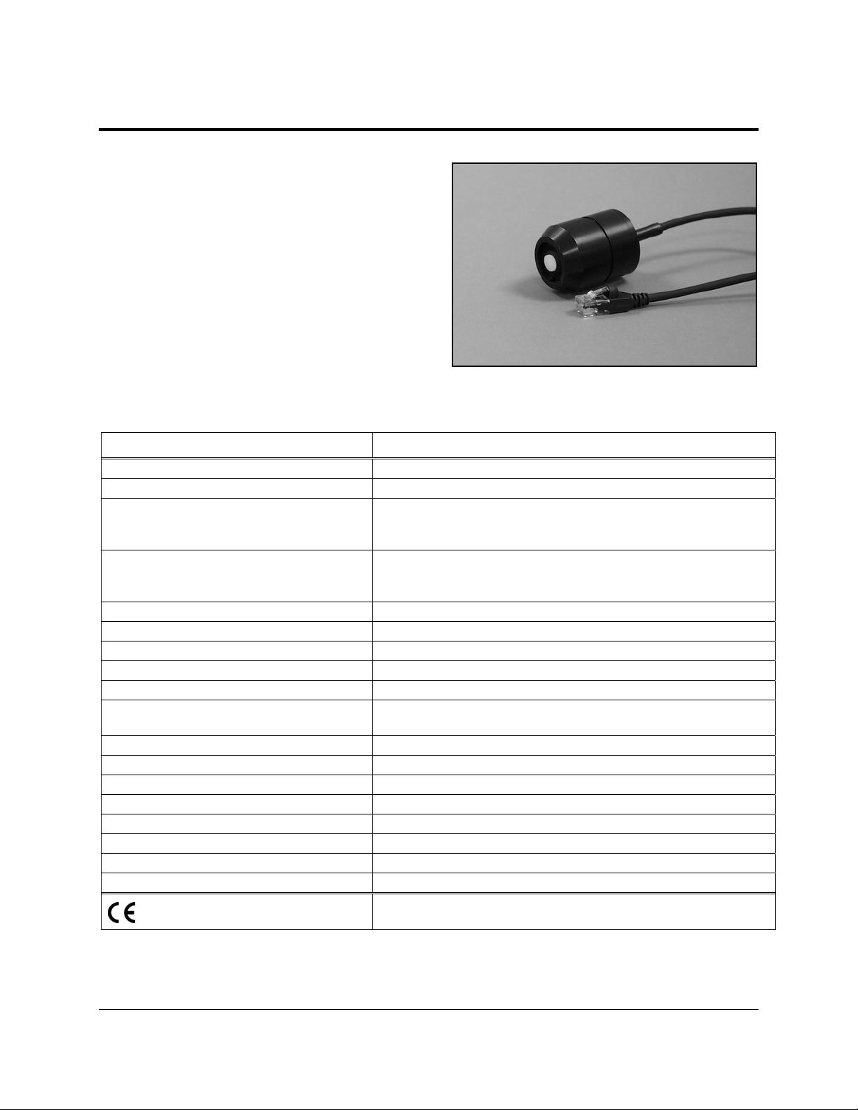
The Silicon Pyranometer smart sensor is designed to
work with the HOBO
®
Weather Station logger. The
smart sensor has a plug-in modular connector that
allows it to be added easily to a HOBO Weather
Station. All calibration parameters are stored inside
the smart sensor, which automatically communicates
configuration information to the logger without the
need for any programming, calibration, or extensive
setup.
Inside this Package
• Silicon Pyranometer smart sensor
Specifications Silicon Pyranometer Smart Sensor
Measurement Range 0 to 1280 W/m2
Spectral Range 300 to 1100 nm (see Figure 4)
Accuracy
Angular Accuracy
Resolution 1.25 W/m2
Drift < ±2% per year
Calibration Factory recalibration available
Operating Temperature Range -40° to +75°C (-40° to +167°F)
Environmental Rating Weatherproof
Housing
Dimensions 4.1 cm height x 3.2 cm diameter (1 5/8 in. x 1 1/4 in.)
Weight 120 g (4 oz)
Bits per Sample 10
Number of Data Channels * 1
Measurement Averaging Option Yes
Cable Length Available 3.0 m (9.8 ft)
Length of Smart Sensor Network Cable * 3.0 m (9.8 ft)
Part Number S-LIB-M003
Typically within ± 10 W/m
sunlight; Additional temperature induced error ± 0.38 W/m
from +25°C (0.21 W/m
Cosine corrected 0 to 80 degrees from vertical (see Figure 5);
Azimuth Error < ±2% error at 45 degrees from vertical, 360
degree rotation
Anodized aluminum housing with acrylic diffuser and O-ring
seal
The CE Marki
relevant directives in the European Union (EU).
ng identifies this product as complying with all
* A single HOBO Weather Station can accommodate 15 data channels and up to 100 m
(328 ft) of smart sensor cable (the digital communications portion of
2
or ± 5%, whichever is greater in
2
/°F from +77°F)
the sensor cables).
2
/°C
© 2001–2010 Onset Computer Corporation. Onset and HOBO are trademarks of Onset Computer Corporation.
Part #: MAN-S-LIB
Doc #: 6708-D
Page 2
Silicon Pyranometer Smart Sensor
Mounting
Accessories
• Light Sensor Mounting Bracket (Part # M-LBB)
• Light Sensor Level (Part # M-LLA)
Bracket Mounting
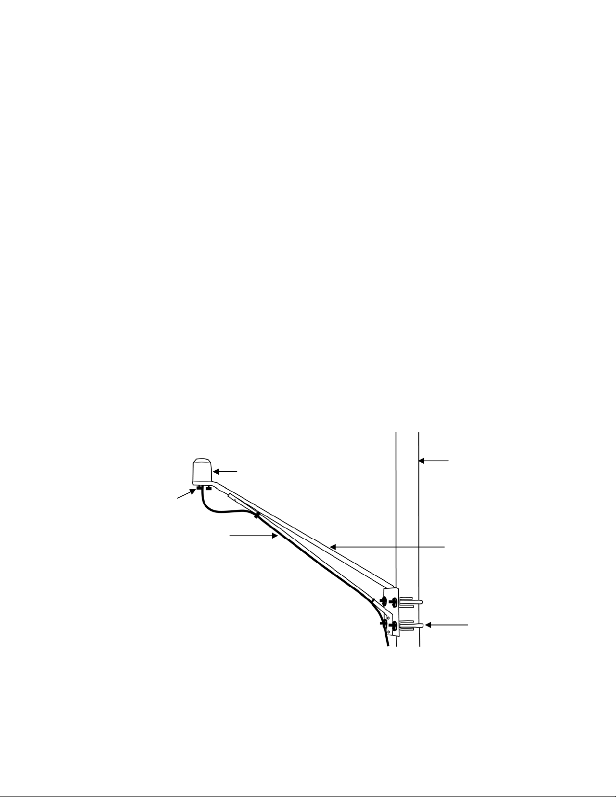
It is recommended that you mount the Silicon Pyranometer smart sensor with the light sensor bracket on a
pole or tripod (see Figure 1). To mount the sensor using the bracket:
1. Attach the light sensor bracket to a 1¼ inch to 1
Note: The bracket can also be mounted on a flat, vertical surface using four screws.
2. Position the Silicon Pyranometer sensor on top of the bracket with its cable running through the
slot in the bracket.
3. Using the two screws supplied, attach the sensor to the bracket through the two holes on either
side of the slot.
Note: Do not completely tighten the screws until you level the sensor.
5
/8 inch pole with the provided U-bolts.
4. Position the bracket so it faces toward the equator, minimizing the chance of shading.
5. Mount the bracket on the mast with the two U-bolt assemblies, mounting it high enough on the
mast to avoid the possibility of shading the sensor.
Note: If you mount the sensor above eye level, use a step ladder or other secure platform when
leveling the sensor so that you can clearly view the Light Sensor Level (Part # M-LLA).
Silicon Pyranometer
Smart Sensor
Thumbscrews
Silicon Pyranometer
Sensor Cable
Mast
Light Sensor Bracket
U-bolt Assembly
Figure 1: Silicon Pyranometer Sensor Bracket Mounting
6. Make sure the screws holding the sensor to the mounting bracket are loose.
Page 2 of 6
Page 3
Silicon Pyranometer Smart Sensor
7. Place the Light Sensor Level on the Silicon Pyranometer smart sensor.
8. Adjust the height of the thumbscrews to level the sensor (start with the thumbscrews protruding
about 1/16
inch from the bracket).
9. Once the sensor is near level, tighten the Phillips head screws.
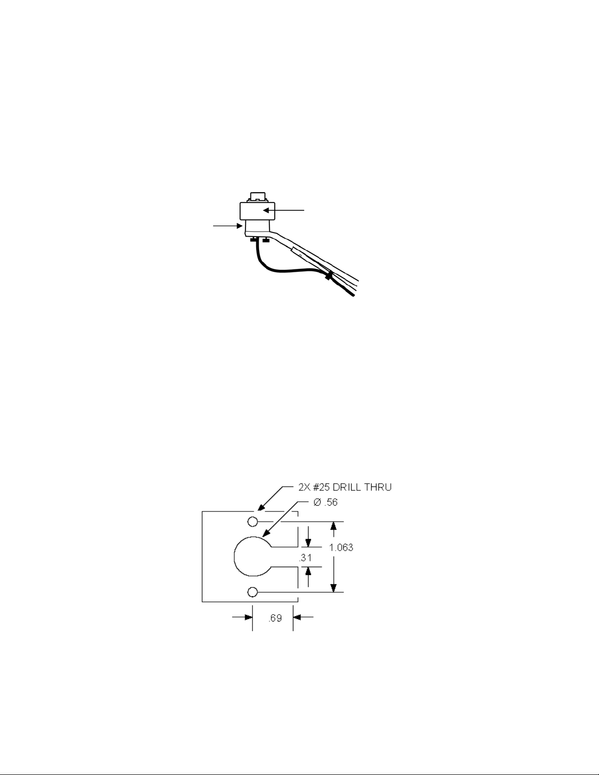
10. Check the level and repeat above steps if necessary (see Figure 2).
11. IMPORTANT: Don’t forget to remove the level when you are done with it.
Light Sensor Level
Silicon
Pyranometer
Sensor
Figure 2: Leveling the Sensor on the Light Sensor Bracket
(Remove for Operation)
Specialized Application Mounting
To mount the Silicon Pyranometer sensor using a mounting plate of your own design:
1. Drill a 0.56 (9/16) inch hole in the middle of the plate, then drill two #25 holes 1.063 (1-1/16)
inches apart on either side of the center hole. Cut a 0.31 (5/16) inch-wide slot in the mounting
plate. See Figure 3. The plate should be a thickness of 1/8 inch or less.
2. Slide the sensor through the 0.31 (5/16) inch-wide slot.
3. Attach the sensor using two 6-32 x 3/8 inch screws and lock washers (not included).
4. Shim the sensor as necessary to level it.
Figure 3: Recommended Mounting Plate Dimensions
Page 3 of 6
Page 4

Silicon Pyranometer Smart Sensor
Mounting Considerations
• Small errors in alignment can produce significant errors. Be certain the sensor is mounted level.
• Mount the sensor where it will not be in a shadow. Any obstruction should be below the plane of
the sensor head. If that is not possible, try to limit obstructions to below 5 degrees, where the
effect will be minimal.
• If possible, avoid placing the sensors in dusty locations. Dust, pollen, and salt residue that collect
on the top of the sensor can significantly degrade accuracy.
• Refer to the HOBO Weather Station User’s Guide for more information about setting up
complete HOBO Weather Stations.
Connecting the Sensor to the Logger
To start using the Silicon Pyranometer smart sensor, stop the HOBO Weather Station logger and insert
the modular jack into an available port. If a port is not available, use a 1-to-2 adaptor, which allows you to
plug two sensors into one port (Part # S-ADAPT). The next time you use the HOBO Weather Station, it
will automatically detect the new smart sensor.
The HOBO Weather Station supports a maximum of 15 data channels; this sensor uses one channel.
Launch the logger and verify the sensor is functioning correctly. See the HOBO Weather Station User’s
Guide for more details about connecting smart sensors to the HOBO Weather Station.
Operation
The Silicon Pyranometer smart sensor supports measurement averaging. When measurement averaging is
enabled, data is sampled more frequently than it is logged. The multiple samples are then averaged
together and the average value is stored as the data for the interval. For example, if the logging interval is
set at 10 minutes and the sampling interval is set at 1 minute, each recorded data point will be the average
of 10 measurements.
Measurement averaging is useful for reducing noise in the data. It is recommended that you use
measurement averaging whenever the Silicon Pyranometer smart sensor is placed in an area where the
light level can vary quickly with respect to the logging interval (for example, during partly cloudy
conditions). Note that fast sampling intervals (less than 1 minute) may significantly reduce battery life.
See the HOBO Weather Station User’s Guide for more details about sensor operation and battery life.
Page 4 of 6
Page 5
Silicon Pyranometer Smart Sensor
Spectral Characteristics
This sensor uses a silicon photodiode to measure solar power per unit area (watts per square meter).
Silicon photodiodes are not ideal for use as solar radiation sensors and the photodiode in this Silicon
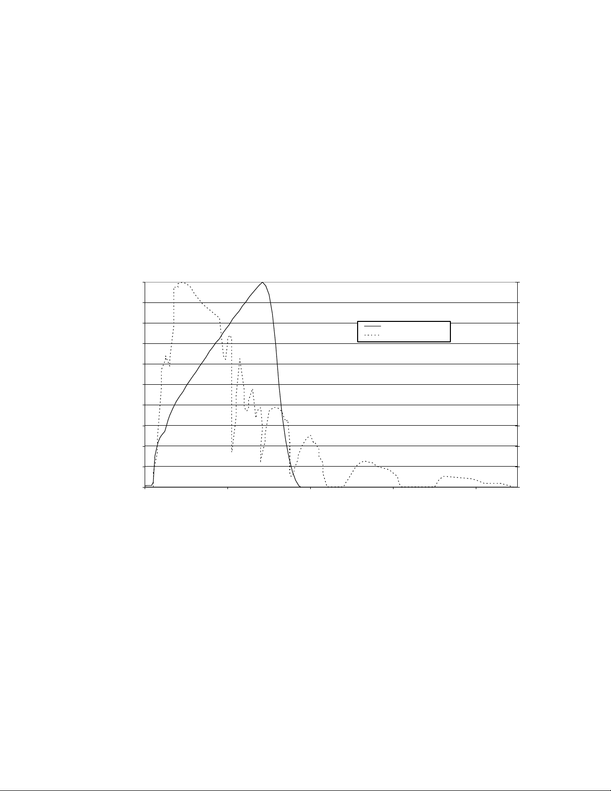
Pyranometer is no exception (see Figure 4). An ideal pyranometer has equal spectral response from 280 to
2800 nm. However, when calibrated properly and used correctly, the Silicon Pyranometer smart sensor
should perform well in most situations.
The sensor is calibrated for use in sunlight (an Eppley Precision Spectral Pyranometer is used as reference
standard). Accordingly, if the sensor is used under natural sunlight, the measurement errors will be small.
Note that significant errors may result from using the sensor under artificial light, within plant canopies,
in greenhouses, or any other conditions where the spectral content differs from sunlight.
Sun's Relative Intensity and the Typical Relative Response of
the Silicon Pyranometer versus Wavelength
1.0
0.9
0.8
0.7
0.6
0.5
0.4
0.3
Silicon Pyranometer
Sunlight
Sun's Relative Intensity
0.2
0.1
0.0
250 750 1250 1750 2250
Wavelength (nm)
Figure 4: S-LIB-M003 Silicon Pyranometer Response Curve
1.0
0.9
0.8
0.7
0.6
0.5
0.4
0.3
0.2
Photodetector Relative Response
0.1
0.0
Page 5 of 6
Page 6
Silicon Pyranometer Smart Sensor
Cosine Correction
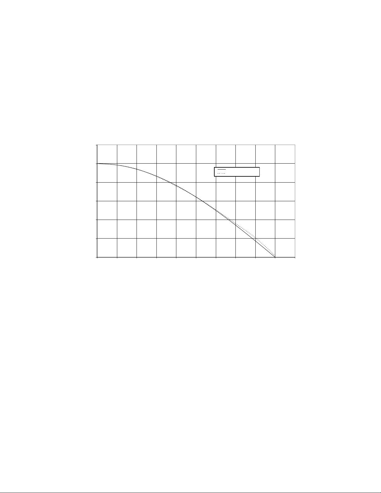
The Silicon Pyranometer smart sensor housing is designed to give an accurate cosine response. Figure 5
shows a plot of relative intensity versus angle of incidence for a typical sensor and for the theoretical ideal
response. Deviation from ideal response is less than 5% from 0 to 70 degrees and less than 10% from 70
to 80 degrees.
Note that as the angle approaches 90 degrees, the ideal cosine response approaches zero. As a result,
small errors in measured intensity will result in very large percentage errors compared to the ideal
response from 80 to 90 degrees.
Typical Cosine Response of Silicon Pyranometer
120
100
80
60
40
Percent Relative Response
20
0
0 102030405060708090100
Angle from Vertical (Degrees)
Ideal Response
Silicon Pyranometer
Figure 5: S-LIB-M003 Typical Cosine Response Curve
Maintenance
Dust on the sensor will degrade sensor accuracy. Periodically inspect the sensor and if necessary, gently
clean the diffuser with a damp sponge. Do not open the sensor as there are no user serviceable parts
inside.
Warning: DO NOT use alcohol, organic solvents, abrasives, or strong detergents to clean the diffuser
element on the Silicon Pyranometer smart sensor. The acrylic material used in the sensor can be crazed by
exposure to alcohol or organic solvents. Clean the sensor only with water and/or a mild detergent such as
dishwashing soap if necessary. It is recommended that you use vinegar to remove hard water deposits
from the diffuser element. Under no circumstances should the sensor be immersed in any liquid.
Verifying Sensor Accuracy
It is recommended that you test the Silicon Pyranometer smart sensor annually for accuracy. If the sensor
is not providing accurate data, it may be damaged or out of calibration. If you are unsure of accuracy,
send the smart sensor back to Onset for testing and possible re-calibration. Only Onset can complete
calibration. Contact Onset or your dealer for a Return Merchandise Authorization (RMA) number before
sending the sensor.
Page 6 of 6
 Loading...