

Page 1
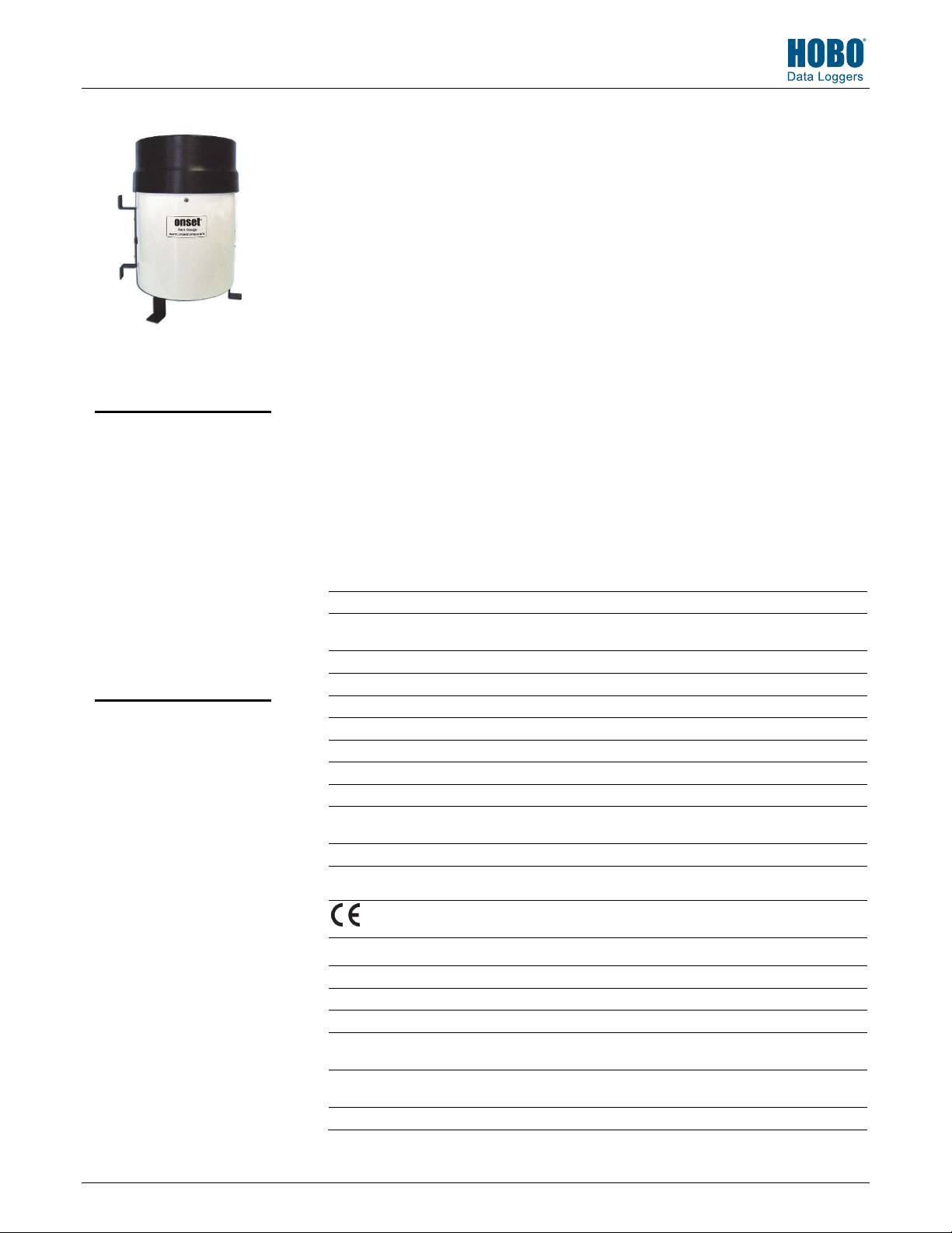
HOBO® Data Logging Rain Gauge (RG3 and RG3-M) Manual
Test Equipment Depot - 800.517.8431
The Data Logging Rain Gauge consists of two major components: a Tipping-bucket Rainfall
Collector, and a HOBO
The collector consists of a black powder-coated aluminum knife-edged ring, screen, and funnel
assembly that diverts rainwater to a tipping-bucket mechanism located in an aluminum
housing. The housing is white powder-coated aluminum designed to withstand years of
exposure to the environment. The tipping-bucket mechanism is designed such that one tip of
the bucket occurs for each 0.01" (RG3) or 0.2 mm (RG3-M) of rainfall. Each bucket tip is
detected when a magnet attached to the tipping-bucket actuates a magnetic switch as the
bucket tips, thus effecting a momentary switch closure for each tip. The spent rainwater then
drains out of the bottom of the housing. The switch is connected to a HOBO
Event/Temperature data logger, which records the time of each tip.
The data logger is a rugged, weatherproof event logger with a 10-bit temperature sensor. It can
record 16,000 or more measurements and tips. It uses a coupler and optical base station with
HOBO Data Logging
Rain Gauge
USB interface for launching and data readout by a computer. Data shuttle options are also
available.
Note: The HOBO Event/Temperature data logger and the Tipping-bucket Collector have
RG3, RG3-M
separate serial numbers. The logger serial number is visible through the logger housing and is
also recorded in the HOBOware data file (.hobo file). The Tipping-bucket Collector serial
Included Items:
• HOBO Pendant® Event
logger
• Mounting Accessories: Two
hose clamps, three screws
number is found on both the collector housing product label and the packing box. Take a
moment and record the serial numbers here: HOBO Event/Temperature Data Logger Serial
Number: _________________ Tipping-bucket Collector Serial Number: __________________
Specifications
- 99 Washington Street Melrose, MA 02176 - TestEquipmentDepot.com
®
Event/Temperature Data Logger.
Required Items:
• HOBOware® 2.1 or later (go
to www.onsetcomp.com/
hoboware-free-download
• Optic USB base station and
coupler (BASE-U-1)
Rain Gauge
Maximum Rainfall Rate 12.7 cm (5 in.) per hour
Calibration Accuracy ±1.0% (up to 2 cm per hour for the RG3-M or up to 1 in. per hour
Resolution 0.2 mm (RG3-M) or 0.01 in. (RG3)
Calibration Requires annual field calibration, see Field Calibration section
Operating Temperature Range 0° to 50°C (32° to 122°F)
Storage Temperature Range -20° to 70°C (-4° to 158°F)
Environmental Rating Weatherproof
Housing 15.24 cm (6 in.) aluminum collector and base
Tipping-bucket Mechanism Stainless steel shaft with brass bearings
Dimensions 25.72 cm height x 15.24 cm diameter (10.125 x 6 in.);
Weight
Part Numbers RG3 (0.01 in. per tip)
Logger
Time Stamp Resolution 1.0 second
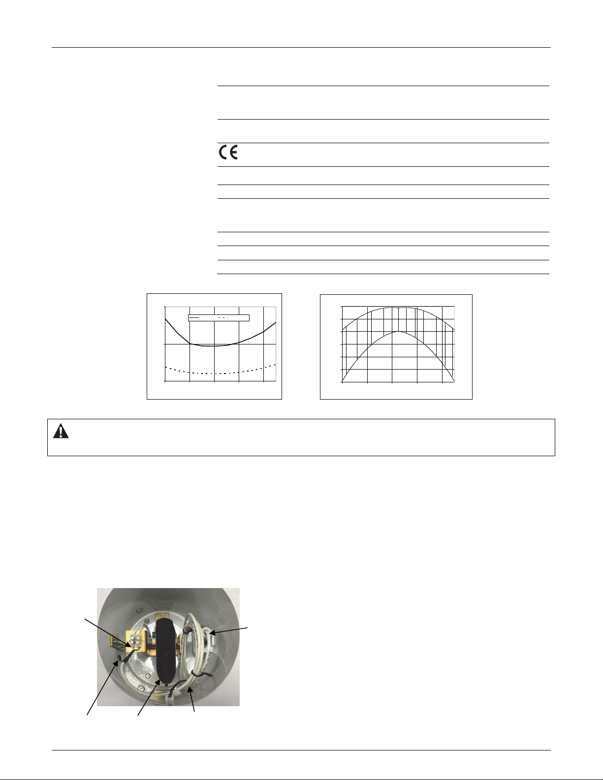
Time Accuracy ±1 minute per month at 25°C (77°F), see Plot B
Operating Range -20° to 70°C (-4° to 158°F)
Environmental Rating (for Logger
Used Outside of Rain Gauge)
NIST Traceable Certification Available for temperature only at additional charge; temperature
Battery CR-2032 3V lithium battery; 1 year typical use
for the RG3)
15.39 cm (6.06 in.) receiving orifice
1.2 Kg (2.5 lbs)
RG3-M (0.2 mm per tip)
The CE Marking identifies this pr
relevant directives in the European Union (EU).
Tested to NEMA 6 and IP67; suitable for deployment outdoors
range -20° to 70°C (-4° to 158°F)
oduct as complying with all
10241-M MAN-RG3/RG3-M
Page 2
Specifications (continued)
HOBO Data Logging Rain Gauge (RG3 and RG3-M) Manual
Memory 64K bytes – 16K to 23K when recording events only; 25K to 30K
Materials Polypropylene case; stainless steel screws; Buna-N O-ring; PVC
Temperature Measurement (see Using the Logger for Temperature Measurement section)
Measurement Range -20° to 70°C (-4° to 158°F)
Accuracy ±0.54°C from 0° to 50°C (± 0.97°F from 32° to 122°F), see Plot A.
Resolution 0.10°C at 25°C (0.18°F at 77°F), see Plot A
Drift Less than 0.1°C/year (0.2°F/year)
Response Time Airflow of 1 m/s (2.2 mph): 10 minutes, typical to 90%
1
Accuracy Resoluti on
0.5
Accuracy/Resolution (°C)
0
-20 0 20 40 6 0
Temperature (°C)
Plot A Plot B
data points when recording events and temperature; see Data
Storage.
cable insulation
The CE Marking identifies this
product as complying with all
relevant directives in the European Union (EU).
A solar radiation shield is required for accurate temperature
measurements in sunlight.
25
0
-25
-50
-75
Timebase Error ( ppm)
-100
-125
-20 0 20 40 60
Temperature (°C)
WARNING: The black powder-coated aluminum knife-edged ring is extremely sharp and can cause injury if not handled properly. Do
not press edge against any body parts as severe cuts and bleeding may occur.
Accessing the Logger
To access the logger, unscrew the thumbscrews that secure the
ring, screen, and funnel assembly to the rain gauge housing.
Logger-to-Rain Gauge Connection
The logger’s black and white input wires are connected to the
tipping-bucket output by a terminal block as shown at left.
Remove the assembly from the housing by pulling the ring up
while holding down the housing. The logger can then be seen
installed in its holder inside the rain gauge housing as shown
below. When reassembling the ring on the logger housing, align
the thumbscrews with the slots (if there are slots in the
housing). Screw the thumbscrews in, making sure they go
through the slots.
Logger Deployment Considerations
Ensure logger cable does not interfere with the operation of
the tipping-bucket mechanism! When logger is not deployed
outside of the rain gauge housing, cable should be neatly coiled
with no sharp bends, secured with cable ties, and placed
between tipping-bucket holder and logger holder (shown at
left). Logger should be placed securely in its holder.
Logger input
connections
(black and
white wires
connected to
bottom
terminal block;
may be under a
rubber
terminal cover)
Data
logger in
holder
Using the Logger for Temperature Measurement
To use the logger to record temperature, it must be deployed
outside of the rain gauge housing in a suitable solar radiation
shield (such as those supplied by Onset) to ensure accurate
temperature measurements.
1. If you have not already done so, unscrew the thumbscrews
that secure the ring, screen, and funnel assembly to the rain
gauge housing. Remove the assembly from the housing by
pulling the ring up while holding down the housing.
Grommet
Tipping-bucket
mechanism
Logger cable coiled and
tied, no interference with
tipping-bucket mechanism
Carefully cut any cable ties that secure the cable.
2
Page 3

HOBO Data Logging Rain Gauge (RG3 and RG3-M) Manual
2. If there is a rubber cover on the terminal block, remove it.
Unscrew the two terminal block screws that secure the
logger’s black and white input wires. Note: Screws do not
have to be completely removed—only enough to slide out
the wires.
3. Remove logger and cable from inside the housing.
4. From outside of housing, feed the wire end of the cable
through the rubber grommet. Slide the wires back into the
terminal block until no bare wire is showing, but only far
enough so that the terminal block screws clamp down on
the bare wire and not the black and white insulation. (The
polarity of the input connection is not important.) Tighten
the terminal block screws and then gently tug the wires to
ensure they are secure. Make sure any excess cable inside
of housing is secured so that it does not interfere with the
operation of the tipping-bucket mechanism! If possible,
create service loop for cable by using two small cable ties to
loop and secure cable to cable tie mount as shown below.
Connect
logger
wires to
terminal
Insert
logger
cable
through
grommet
Tie up excess
cable and
secure it to
cable tie
mount inside
the housing
5. Place the ring assembly back on the housing. If there are
slots in the housing, align the thumbscrews with the slots
when reassembling. Screw the thumbscrews in, making sure
they go through the slots.
Connecting the Logger to a Computer
The HOBO Event/Temperature data logger requires an Onsetsupplied Optic USB Base Station and Coupler (BASE-U-1), and
HOBOware version 2.1 or later software to connect to
computer. If possible, avoid connecting at temperatures below
0°C (32°F) or above 50°C (122°F).
1. Plug the USB connector on the base station into an available
USB port on your computer.
2. Insert the logger and the base station into the coupler, as
shown below. Make sure that the logger is inserted in the
end of the coupler that has the magnet, and that the ridges
on the base station and logger are aligned with the grooves
in the coupler.
Logger
Ridge
Magnet
Base station
Coupler
3. If the logger has never been connected to the computer
before, it may take a few seconds for the new hardware to
be detected.
4. Use the logger software to launch and read out the logger.
Note: You can read out the logger or check its status while it
continues to log, stop it manually with the software, or let it
record data until the memory is full. Refer to the software
user’s guide for complete details on launching, reading out, and
viewing data from the logger.
Logger Triggered Start
The logger can be configured to start logging at your command
using the magnet in the coupler or any strong magnet to trigger
the start.
1. Use the logger software to launch the logger with Trigger
Start selected for the Default Launch Type. Remove the
logger from the coupler.
2. Bring the logger and the empty coupler, or strong magnet,
to the deployment location.
Important: Any magnet can trigger a start. This can be
helpful, but it can also cause a premature start. Keep the
logger away from strong magnetic fields until you are ready
to begin logging.
3. When you are ready for the logger to start logging, insert
the logger into the empty coupler (or place it next to a
strong magnet) and remove it after three seconds.
Important: The logger will not launch if the coupler is
attached to a base station.
4. Verify that the logger’s light is blinking at least every four
seconds.
Internal Events
Like other U-Series loggers, this logger stores internal events
that are unrelated to the external event input. Internal events
are stored when the coupler is attached or detached, when the
battery drops below approximately 2.7V, when the battery rises
above 2.8V, when a host computer is connected, and when the
logger is stopped by a command from the host software.
Logger Operation
A light (LED) on the front of the logger confirms logger
operation. The following table explains when the light blinks
during logger operation.
When: The light:
The logger is logging
The logger is awaiting a
start because it was
launched in Start At
Interval, Delayed Start, or
Trigger Start mode
Blinks once every one to four
seconds (the shorter the logging
interval, the faster the light blinks);
blinks when logging a sample
Blinks once every eight seconds until
logging begins
Inserting Logger into Base Station
3
Page 4
HOBO Data Logging Rain Gauge (RG3 and RG3-M) Manual
Data Storage
The data logger has 64,000 bytes of nonvolatile data storage.
The logger records a time stamp for each tipping-bucket tip.
Data storage requirements per tip are a function of enabled
channels and logging interval. When tips are three to 12 days
apart, 32 bits are required to record a single tip (16,000 tips).
When tips are less than 16 seconds apart, only 22 bits are
required to record a single tip (23,000 tips). In most cases,
25,000 to 30,000 data points (including tips, temperature,
and/or battery measurements) can be logged. For most rain
gauge applications, battery life, not memory capacity, will be
the factor that limits deployment duration.
Protecting the Logger
Do not store the logger in the coupler. Remove the logger from
the coupler when you are not using it. When the logger is in the
coupler or near a magnet, it consumes more power and will
drain the battery prematurely.
Keep the logger away from magnets. Being near a magnet can
cause false coupler events to be logged. It can also launch the
logger prematurely if it was waiting for a trigger start.
If the logger is used in a humid location, periodically inspect the
desiccant and dry it if it is not bright blue. To dry the desiccant,
remove the desiccant pack and leave the pack in a warm, dry
location until the bright blue color is restored. (Refer to the
“Battery” section for instructions on removing and replacing
the logger cap.)
Temperature range Desiccant maintenance schedule
Less than 30°C (86°F) Approximately once per year
30° to 40°C (86° to 104°F) Approximately every six months
Over 40°C (104°F) Approximately every three months
Note! Static electricity may cause the logger to stop logging.
To avoid electrostatic discharge, transport the logger in the rain
gauge housing or in an anti-static bag, and ground yourself by
touching an unpainted metal surface before handling the
logger. For more information about electrostatic discharge,
search for “static discharge” at www.onsetcomp.com.
Battery
The logger requires one 3-Volt CR-2032 lithium battery. Battery
life varies based on the temperature and the frequency at
which the logger is recording data (the logging interval). A new
battery typically lasts one year with logging intervals greater
than one minute or if used for rainfall logging only.
Deployments in extremely cold or hot temperatures, or logging
intervals faster than one minute, may significantly reduce
battery life. Continuous logging at the fastest logging rate of
one second will deplete the battery in as little as two weeks. To
replace the battery:
1. Remove the two screws that secure the end cap to the case
and remove the cap as shown below. The circuit board is
attached to the cap.
Battery Replacement
2. Examine the desiccant pack that is tucked below the battery
holder. If the desiccant is not bright blue, put the desiccant
pack in a warm, dry place until the blue color is restored.
3. Carefully push the battery out of the holder with a small,
nonmetallic blunt instrument.
4. Insert a new battery, positive (+) side facing up.
5. Return the circuit board, desiccan
t pack, and label to the
case, carefully aligning the circuit board with the grooves in
the case so that the battery faces the ridged side of the
case.
6. Replace the end cap, ensuring that the O-ring is seated in
the groove, and not pinched or twisted. Make sure no dirt
or lint is trapped on the O-ring, as this could result in a leak.
7. Re-fasten the screws. Do not over-tighten the screws.
WARNING: Do not cut open, incinerate, heat above
85°C (185°F), or recharge the lithium battery. The
battery may explode if the logger is exposed to extreme
heat or conditions that could damage or destroy the
battery case. Do not dispose of the logger or battery in
fire. Do not expose the contents of the battery to water.
Dispose of the battery according to local regulations for
lithium batteries.
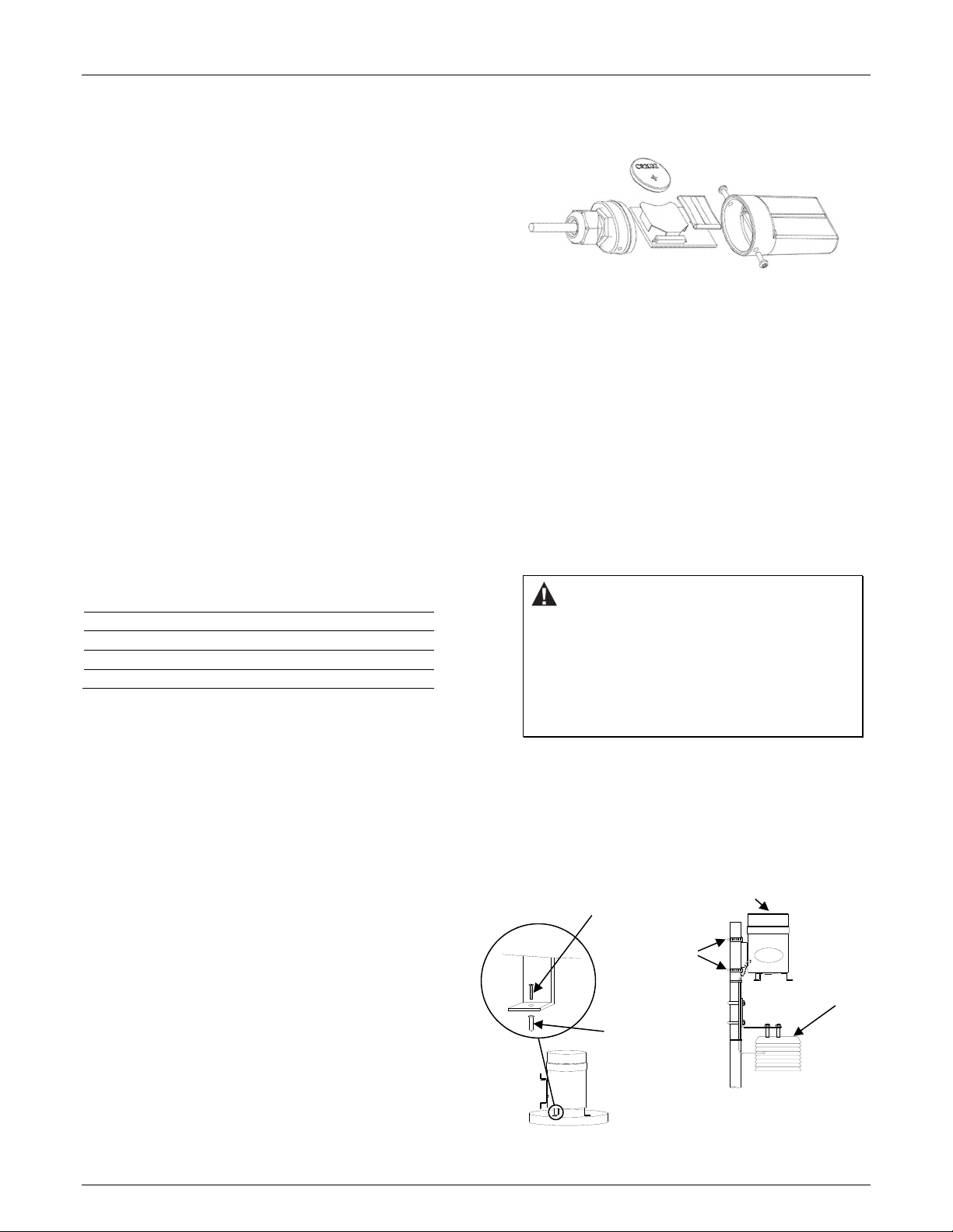
Mounting the Rain Gauge
The rain gauge has provisions for mounting two ways, surface
mounting and pole mounting (see below). Surface mounting is
recommended where possible. Note: The Pole or Mast Mounting
diagram shows the logger deployed outside of the rain gauge
housing, mounted inside an optional solar radiation shield.
Screws
(Supplied)
Screw Plug Insert
(For Concrete Surfaces)
Ensure top of Rain Gauge is
above top of Pole
Hose Clamps
(Supplied)
Optional Solar
Radiation Shield
Surface Mounting
4
Pole or Mast Mounting
Page 5
HOBO Data Logging Rain Gauge (RG3 and RG3-M) Manual
Notice! During shipment, the tipping assembly has been
secured to avoid possible damage to the pivot assembly. Before
installation, remove the rubber band inside the housing to
release the tipping-bucket mechanism. After the rain gauge is
installed, remove the collector ring assembly and verify that the
tipping-bucket mechanism is not in the dead-center position.
Press either end of the tipping-bucket down against the stop to
be sure that it is not centered.
General Mounting Considerations
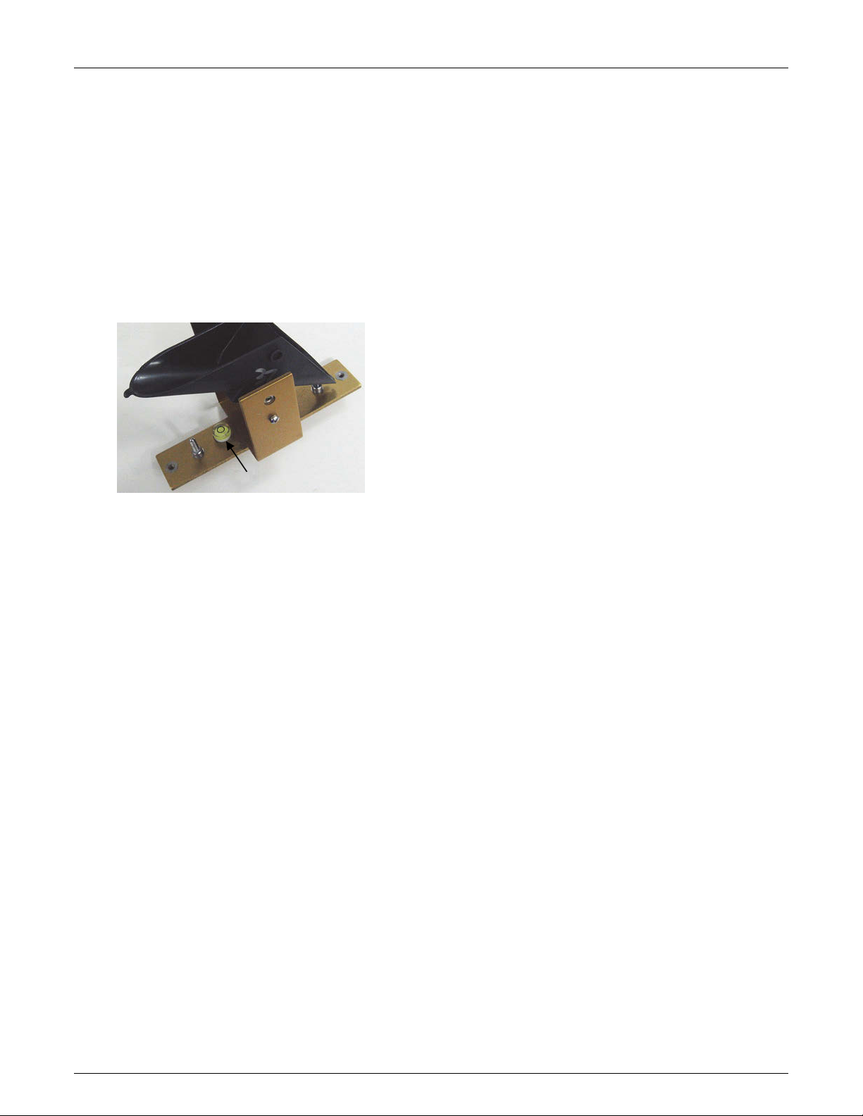
• The rain gauge housing MUST be mounted in a LEVEL
position. Use the bubble level underneath the tippingbucket mechanism shown below. The rain gauge is level
when the bubble is within the circle on the level.
• A clear and unobstructed mounting location is necessary to
obtain accurate rainfall readings. Tall objects can interfere
with accurate rain measurements. It is recommended that
you place the rain gauge away from the obstruction by a
distance greater than three times the height of the
obstruction. If that is not possible, raise the rain gauge as
high as possible to avoid shedding.
• Avoid splashing and puddles. Be sure the gauge is high
enough above any surface that rain will not splash into the
top of the collector.
• Vibration can significantly degrade accuracy of the tippingbucket mechanism. In windy locations make sure that the
bucket will be vibration-free.
• For maximum sensitivity in low-moisture environments you
can remove the collector screen. This eliminates water
retention on the screen which could evaporate before being
measured. The tradeoff is that without the screen, debris
can get into the funnel and clog the orifice. To remove the
screen you need to first remove the spring clip inside the
collector.
Horizontal Surface Mounting
If mounting the Rain Gauge on a horizontal surface
(recommended):
1. The rain gauge housing MUST be mounted in a LEVEL
position, clear of overhead structures, and in a location free
from vibration.
2. Use the rain gauge as a template by placing the housing on
the mounting surface and marking the holes for the three
mounting ‘feet.’ Note: The three mounting holes are
equally spaced on a 16.99 cm (6.688 in.) diameter circle.
3. For wood surfaces, drill three 0.16 cm (1/16 in.) diameter
holes.
4. For concrete, drill three appropriately sized holes with a
masonry bit, and install screw plug inserts.
5. Use shims as required to level the rain gauge.
6. Secure the rain gauge mounting feet with the three screws
supplied with the rain gauge.
Pole or Mast Mounting
If mounting the Rain Gauge on a pole or mast:
1. The rain gauge housing MUST be mounted in a LEVEL
position, clear of overhead structures, and in a location free
from vibration.
2. Ensure that the pole or mast is properly guyed so that
vibration in high winds is kept to a minimum.
3. Ensure that the pole or mast is vertical.
4. Top of rain gauge should be above top of pole.
5. Use the two supplied hose clamps to mount the rain gauge
on pole or mast:
a. Open each hose clamp and place it around the pole.
b. Close the hose clamps until the rain gauge side bracket
easily slides into the clamp.
c. Hold the rain gauge bracket against the pole with the
top of the rain gauge above the top of the pole.
d. Slip the upper clamp over the side bracket and tighten
the clamp until the rain gauge is secure. Note: Be sure
the collector is above the top of the mast so you don’t
get any splashing, wind, shedding, or shadow effects.
e. Install the lower clamp.
f. Ensure that the top of the rain gauge is level and above
the top of the pole.
Maintenance
Clean the filter screen, funnel, and tipping-bucket mechanism
with mild soap and water and a cotton swab. To remove screen
for cleaning, remove the spring clip from inside the collector.
Clean the screen and funnel. Replace the screen and the spring
clip. An accumulation of dirt, bugs, etc. on the tipping-bucket
will adversely affect the calibration. Oil the needle bearings
with light oil on an annual basis. In harsh environments, it is
recommended that you lubricate the needle bearings more
frequently.
Field Calibration
The tipping-bucket mechanism is a simple and highly reliable
device. Absolutely accurate rain gauge calibration can be
obtained only with laboratory equipment, but an approximate
field check can be easily done. The rain gauge must be
calibrated with a controlled rate of flow of water through the
tipping-bucket mechanism. The maximum rainfall rate that the
rain gauge smart sensor can accurately measure is one inch of
rain per hour (36 seconds between bucket tips). Therefore, the
rain gauge should be field calibrated using a water flow rate
equivalent to, or less than, one inch of rain per hour (more than
36 seconds between bucket tips). If the flow rate is increased, a
properly calibrated instrument will read low. Decreasing the
rate of flow will not materially affect the calibration.
5
Page 6
HOBO Data Logging Rain Gauge (RG3 and RG3-M) Manual
The reason for this is obvious if the tipping-bucket assembly is
observed in operation. With water falling into one side of the
tipping-bucket, there comes a point when the mass of the
water starts to tip the bucket. Some time is required for the
bucket to tip (a few milliseconds). During the first 50% of this
tipping time water continues to flow into the filled bucket; the
last 50% of this tipping time water flows into the empty bucket.
The amount of water flowing during the first 50% of time is
error, the faster the flow rate the greater the error. At flow
rates of one inch per hour (20 mm/hr) or less, the water
actually drips into the buckets rather than flowing. Under this
condition, the bucket tips between drips, and no error water is
added to a full moving bucket.
You can follow the instructions in the next section or you can use
the Texas Electronics Field Calibration Kit to easily calibrate the
rain gauge. See http://texaselectronics.com/products/partsaccessories/field-calibration-kit.html.
To Check Calibration
1. Obtain a plastic or metal container of at least one liter
capacity. Make a very small hole (a pinhole) in the bottom
of the container.
2. Place the container in the top funnel of the Rain Gauge. The
pinhole should be positioned so that the water does not
drip directly down the funnel orifice.
3. Follow the instructions for the Rain Gauge model you have:
• RG3: Pour exactly 473 ml of water into the container.
Each tip of the bucket represents 0.01 inch of rainfall.
• RG3-M: Pour exactly 373 ml of water into the container.
Each tip of the bucket represents 0.2 mm of rainfall.
4. If it takes less than one hour for this water to run out, then
the hole (from step 1) is too large. Repeat the test with a
smaller hole.
5. Successful field calibration of this sort should result in one
hundred tips plus or minus two.
6. Adjusting screws are located on the outside bottom of the
Rain Gauge housing. These two socket head set screws
require a 5/64 inch Allen wrench. Turning the screws
clockwise increases the number of tips per measured
amount of water. Turning the screws counterclockwise
decreases the number of tips per measured amount of
water. A 1/4 turn on both screws either clockwise or
counterclockwise increases or decreases the number of tips
by approximately one tip. Adjust both screws equally; if you
turn one a half turn, then turn the other a half turn.
7. Repeat Steps 3–6 as necessary until the Rain Gauge has
been successfully calibrated.
© 2005–2018 Onset Computer Corporation. All rights reserved. Onset, HOBO, and HOBOware are registered
trademarks of Onset Computer Corporation. All other trademarks are the property of their respective companies.
This product has been manufactured by Onset Computer Corporation and in compliance with Onset’s ISO 9001:2015
Quality Management System.
Patent #: 6,826,664 10241-M MAN-RG3/RG3-M
 Loading...