

Page 1
NE570
2
;
Compandor
The NE570 is a versatile low cost dual gain control circuit in which
either channel may be used as a dynamic range compressor or
expandor. Each channel has a full−wave rectifier to detect the average
value of the signal, a linerarized temperature−compensated variable
gain cell, and an operational amplifier.
The NE570 is well suited for use in cellular radio and radio
communications systems, modems, telephone, and satellite
broadcast/receive audio systems.
Features
• Complete Compressor and Expandor in One IC
• Temperature Compensated
• Greater than 110 dB Dynamic Range
• Operates Down to 6.0 V
• System Levels Adjustable with External Components
• Distortion may be Trimmed Out
• Pb−Free Packages are Available*
Applications
• Cellular Radio
• Telephone Trunk Comandor
• High Level Limiter
• Low Level Expandor − Noise Gate
• Dynamic Noise Reduction Systems
• Voltage−Controlled Amplifier
• Dynamic Filters
MAXIMUM RATINGS
Rating Symbol Value Unit
Maximum Operating Voltage V
Operating Ambient Temperature Range T
Operating Junction Temperature T
Power Dissipation P
Thermal Resistance, Junction−to−Ambient
Stresses exceeding Maximum Ratings may damage the device. Maximum
Ratings are stress ratings only. Functional operation above the Recommended
Operating Conditions is not implied. Extended exposure to stresses above the
Recommended Operating Conditions may affect device reliability.
DG CELL IN
RECT IN
DC
THD TRIM
R2 20 kW
R1 10 kW
VARIABLE
GAIN
RECTIFIER
CC
A
J
D
R
q
JA
24 V
0 to +70 °C
150 °C
400 mW
105 °C/W
R
3
R
3
20 kW
4
30 kW
V
1.8 V
R
DC
INVERTER IN
REF
−
+
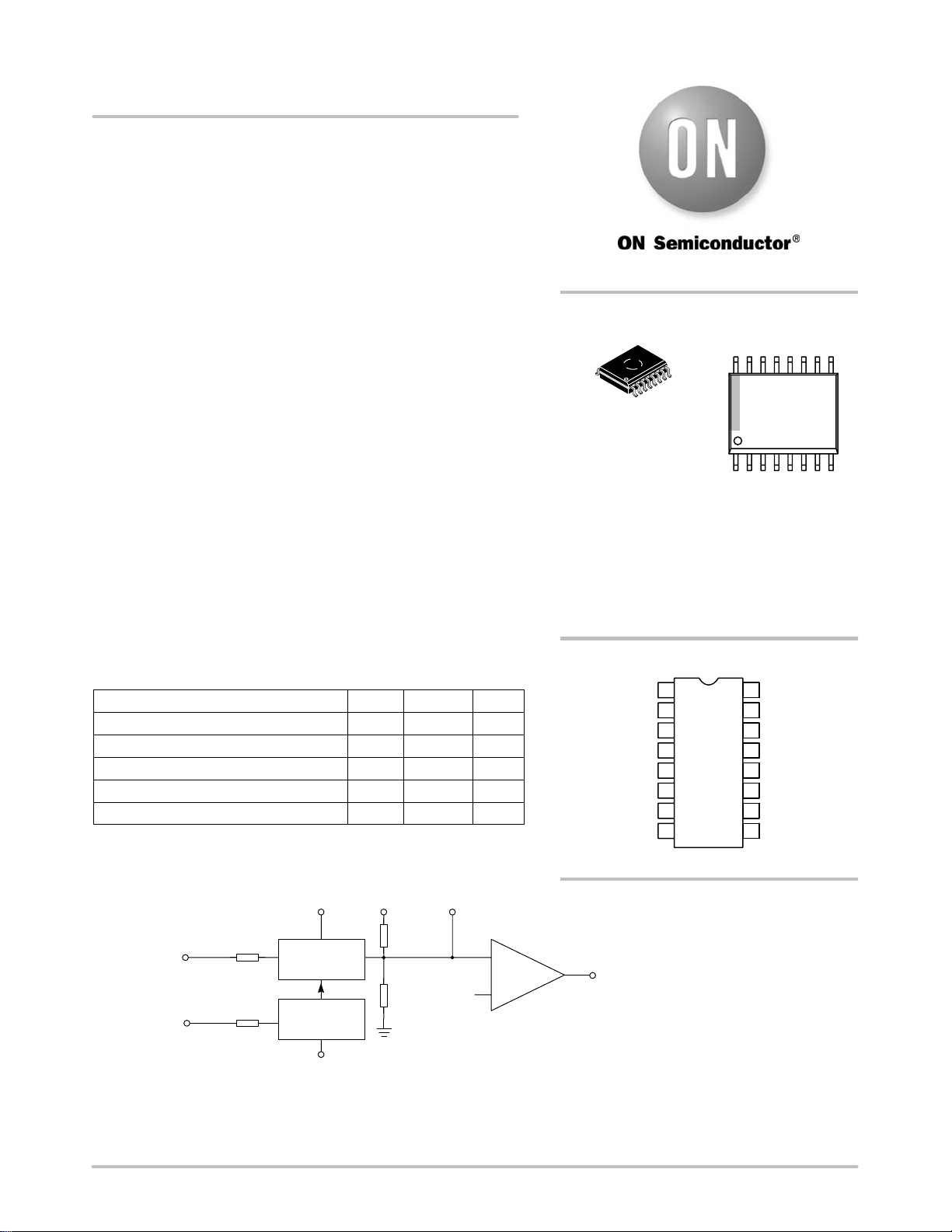
http://onsemi.com
MARKING
DIAGRAM
16
1
SOIC−16 WB
D SUFFIX
CASE 751G
A = Assembly Location
WL = Wafer Lot
YY = Year
WW = Work Week
G = Pb−Free Package
Plastic Small Outline Package
16 Leads; Body Width 7.5 mm
NE570D
AWLYYWWG
1
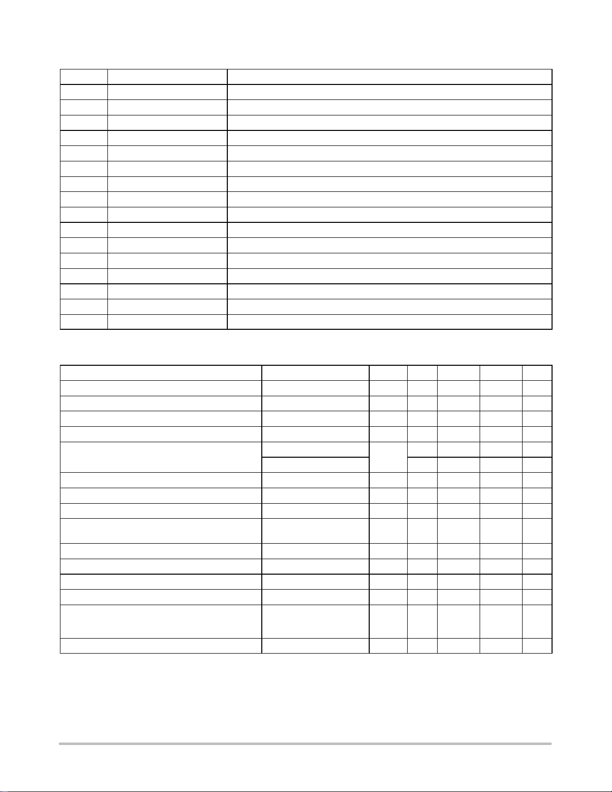
PIN CONNECTIONS
RECT_CAP_1
RECT_IN_1
DG_CELL_IN_1
GND
INV_IN_1
RES_R3_1
OUTPUT_1
THD_TRIM_1
1
2
3
4
5
6
7
8
(Top View)
RECT_CAP_2
16
15
RECT_IN_2
14
DG_CELL_IN_
V
13
CC
INV_IN_2
12
RES_R3_2
11
OUTPUT_2
10
THD_TRIM_2
9
ORDERING INFORMATION
See detailed ordering and shipping information in the package
dimensions section on page 9 of this data sheet.
OUTPUT
RECT CAP
Figure 1. Block Diagram
*For additional information on our Pb−Free strategy and soldering details, please
download the ON Semiconductor Soldering and Mounting Techniques
Reference Manual, SOLDERRM/D.
© Semiconductor Components Industries, LLC, 2006
May, 2006 − Rev. 4
1 Publication Order Number:
NE570/D
Page 2
NE570
PIN FUNCTION DESCRIPTION
Pin Symbol Description
1 RECT CAP 1 External Capacitor Pinout for Rectifier 1
2 RECT IN 1 Rectifier 1 Input
3
DG CELL IN 1
4 GND Ground
5 INV. IN 1 Inverted Input 1
6 RES. R3 1 R3 Pinout 1
7 OUTPUT 1 Output 1
8 THD TRIM 1 Total Harmonic Distortion Trim 1
9 THD TRIM 2 Total Harmonic Distortion Trim 2
10 OUTPUT 2 Output 2
11 RES. R3 2 R3 Pinout 2
12 INV. IN 2 Inverted Input 2
13 V
14
CC
DG CELL IN 2
15 RECT IN 2 Rectifier 2 Input
16 RECT CAP 2 External Capacitor Pinout for Rectifier 2
Variable Gain Cell 1 Input
Positive Power Supply
Variable Gain Cell 2 Input
ELECTRICAL CHARACTERISTICS V
= +15 V, TA = 25 °C; unless otherwise stated.
CC
Characteristic Test Conditions Symbol Min Typ Max Unit
Supply Voltage V
Supply Current No Signal I
Output Current Capability I
CC
CC
OUT
6.0 − 24 V
− 4.3 4.8 mA
±20 − − mA
Output Slew Rate SR − ±0.5 −
Gain Cell Distortion (Note 1)
Untrimmed − 0.3 1.0 %
Trimmed − 0.05 − %
Resistor Tolerance − ±5 ±15 %
Internal Reference Voltage 1.7 1.8 1.9 V
Output DC Shift (Note 2) Untrimmed − ±90 ±150 mV
Expandor Output Noise No signal, 15 Hz to 20 kHz
− 20 45
(Note 3)
Unity Gain Level (Note 4) −1.0 0 +1.0 dBm
Gain Change (Notes 1 and 5) TA = 0°C to +70°C − ±0.1 ±0.2 dB
Reference Drift (Note 5) TA = 0°C to +70°C − ±5.0 ±10 mV
Resistor Drift (Note 5) TA = 0°C to +70°C − +8.0, −5.0 − %
Tracking Error (measured relative to value at unity gain)
equals [VO − VO (unity gain)] dB − V2 dBm
Rectifier Input VCC = +6.0 V
V2 = +6.0 dBm, V1 = 0 dB
V2 = −30 dBm, V1 = 0 dB
−
−
±0.2
+0.2−−0.5, +1.0dBdB
Channel Separation − 60 − dB
1. Measured at 0 dBm, 1.0 kHz.
2. Expandor AC input change from no signal to 0 dBm.
3. Input to V1 and V2 grounded.
4. 0 dB = 775 mV
5. Relative to value at TA = 25°C.
RMS
.
V/ms
mV
http://onsemi.com
2
Page 3
NE570
CIRCUIT DESCRIPTION
The NE570 compandor building blocks, as shown in the
block diagram, are a full−wave rectifier, a variable gain cell,
an operational amplifier and a bias system. The arrangement
of these blocks in the IC result in a circuit which can perform
well with few external components, yet can be adapted to
many diverse applications.
The full−wave rectifier rectifies the input current which
flows from the rectifier input, to an internal summing node
which is biased at V
an external filter capacitor tied to the C
. The rectified current is averaged on
REF
terminal, and
RECT
the average value of the input current controls the gain of the
variable gain cell. The gain will thus be proportional to the
average value of the input signal for capacitively−coupled
voltage inputs as shown in the following equation. Note that
for capacitively−coupled inputs there is no offset voltage
capable of producing a gain error. The only error will come
from the bias current of the rectifier (supplied internally)
which is less than 0.1 mA.
|V
G T
IN
* V
|avg
REF
R
1
or
|V
|avg
G T
IN
R
1
The speed with which gain changes to follow changes in
input signal levels is determined by the rectifier filter
capacitor. A small capacitor will yield rapid response but
will not fully filter low frequency signals. Any ripple on the
gain control signal will modulate the signal passing through
the variable gain cell. In an expander or compressor
application, this would lead to third harmonic distortion, so
there is a trade−off to be made between fast attack and decay
times and distortion. For step changes in amplitude, the
change in gain with time is shown by this equation.
*t
G(t) + (G
initial
t + 10kW C
* G
final
RECT
)e
t
) G
final
The variable gain cell is a current−in, current−out device
with the ratio I
OUT/IIN
controlled by the rectifier. IIN is the
current which flows from the DG input to an internal
summing node biased at V
. The following equation
REF
applies for capacitively−coupled inputs. The output current,
I
, is fed to the summing node of the op amp.
OUT
V
* V
IN
I
+
IN
REF
R
2
+
V
IN
R
2
A compensation scheme built into the DG cell
compensates for temperature and cancels out odd harmonic
distortion. The only distortion which remains is even
harmonics, and they exist only because of internal offset
voltages. The THD trim terminal provides a means for
nulling the internal offsets for low distortion operation.
The operational amplifier (which is internally
compensated) has the non−inverting input tied to V
REF
, and
the inverting input connected to the DG cell output as well
as brought out externally. A resistor , R3, is brought out from
the summing node and allows compressor or expander gain
to be determined only by internal components.
The output stage is capable of ±20 mA output current.
This allows a +13 dBm (3.5 V
) output into a 300 W load
RMS
which, with a series resistor and proper transformer, can
result in +13 dBm with a 600 W output impedance.
A bandgap reference provides the reference voltage for all
summing nodes, a regulated supply voltage for the rectifier
and DG cell, and a bias current for the DG cell. The low
tempco of this type of reference provides very stable biasing
over a wide temperature range.
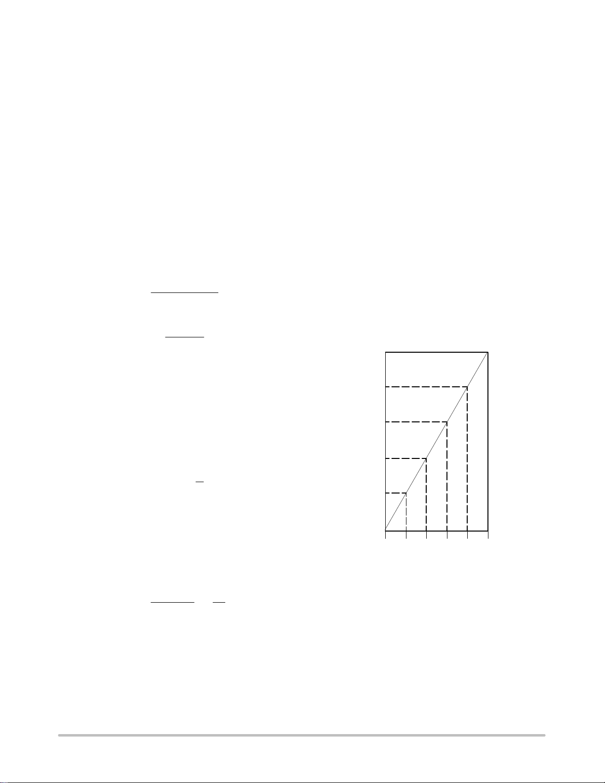
The typical performance characteristics illustration
shows the basic input−output transfer curve for basic
compressor or expander circuits.
+20
+10
0
−10
−20
−30
−40
−50
−60
−70
−80
−40 −30 −20 −10 0 +10
COMPRESSOR OUTPUT LEVEL
COMPRESSOR INPUT LEVEL OR EXPANDOR OUTPUT LEVEL (dBm)
EXPANDOR INPUT LEVEL (dBm)
Figure 2. Basic Input−Output Transfer Curve
OR
http://onsemi.com
3
Page 4

VCC = 15 V
13
NE570
10 mF0.1 mF
6, 11
20 kW
V
1
V
2
3, 14
2.2 mF
2, 15
2.2 mF
20 kW
DG
10 kW
4 1, 16
Figure 3. Typical Test Circuit
INTRODUCTION
Much interest has been expressed in high performance
electronic gain c ontrol c ircuits . F or non−critical appl ications,
an integrated circuit operational transconductance amplifier
can be u sed, b ut w hen h igh−performance is r equired, o ne has
to resort to complex discrete circuitry with many expensive,
well−matched components. This paper describes an
inexpensive inte grated circui t, the NE570 Compandor, which
offers a pair of high performance gain control circuits
featuring low distortion (<0.1 %), high si gnal−to− noise ratio
(90 dB), and wide dynamic range (110 dB).
CIRCUIT BACKGROUND
The NE570 Compandor was originally designed to satis fy
the requirements of the telephone system. When several
telephone channels are multiplexed onto a common line, t he
resulting signal−to−noise ratio is poor and companding is
used to a llow a w ider dynamic range t o be p assed through the
channel. Figure 4 graphically shows what a compandor can
do for the signal−to−noise ratio of a r estri cted d ynamic range
channel. The i nput level range of + 20 dB to − 80 dB is shown
undergoing a 2 −to− 1 c ompressi on w here a 2 .0 dB i nput level
change is c ompress ed i nto a 1 .0 dB o utput l evel c hange b y t he
compressor. The original 100 dB of dynamic range is thus
compressed to a 50 dB range for transmission through a
restricted dynamic range channel. A complementary
expansion on the receiving end restores the original signal
levels and reduces the channel noise by as much as 45 dB.
REF
7, 10
200 pF
V
O
−
+
V
30 kW
5, 12 8, 9
8.2 kW2.2 mF
The significant circuits in a compressor or expander are
the rectifier and the gain control element. The phone system
requires a simple full−wave averaging rectifier with good
accuracy, since the rectifier accuracy determines the (input)
output level tracking accuracy. The gain cell determines the
distortion and noise characteristics, and the phone system
specifications here are very loose. These specs could have
been met with a simple operational transconductance
multiplier, or OTA, but the gain of an OTA is proportional
to temperature and this is very undesirable. Therefore, a
linearized transconductance multiplier was designed which
is insensitive to temperature and offers low noise and low
distortion performance. These features make the circuit
useful in audio and data systems as well as in
telecommunications systems.
INPUT
LEVEL
+20
0 dB
−40
−80
COMPRESSION
NOISE
OUTPUT
LEVEL
EXPANSION
−20
0 dB
−40
−80
http://onsemi.com
4
Figure 4. Restricted Dynamic Range Channel
Page 5

NE570
BASIC CIRCUIT HOOK−UP AND OPERATION
Figure 5 shows the block diagram of one half of the chip,
(there are two identical channels on the IC). The full−wave
averaging rectifier provides a gain control current, IG, for the
variable gain (DG) cell. The output of the DG cell is a current
which is fed to the summing node of the operational
amplifier. Resistors are provided to establish circuit gain and
set the output DC bias.
6, 11
R
20 kW
R
4
INV. INR3
5, 12
3
−
7, 10
+
V
REF
1.8 V
OUTPUT
: PIN 13
V
CC
GND: PIN 4
THD_TRIM
8, 9
R
2
DG_CELL_IN
RECT_IN
3, 14
2, 15
20 kW
R
1
10 kW
C
DG
RECT
I
G
1, 16
30 kW
Figure 5. Chip Block Diagram (1 of 2 Channels)
The circuit is intended for use in single power supply
systems, so the internal summing nodes must be biased at
some voltage above ground. An internal band gap voltage
reference provides a very stable, low noise 1.8 V reference
denoted V
to V
REF
. The non−inverting input of the op amp is tied
REF
, and the summing nodes of the rectifier and DG cell
(located at the right of R1 and R2) have the same potential.
The THD_TRIM pin is also at the V
potential.
REF
Figure 6 shows how the circuit is hooked up to realize an
expander. The input signal, VIN, is applied to the inputs of
both the rectifier and the DG cell. When the input signal
drops by 6.0 dB, the gain control current will drop by a factor
of 2, and so the gain will drop 6 dB. The output level at V
OUT
will thus drop 12 dB, giving us the desired 2−to−1
expansion.
R
3
R
*C
2
IN1
V
IN
*C
IN2
DG
R
R
1
4
−
V
+
REF
V
OUT
Figure 7 shows the hook−up for a compressor. This is
essentially an expander placed in the feedback loop of the op
amp. The DG cell is set−up to provide AC feedback only, so
a separate DC feedback loop is provided by the two RDC and
CDC. The values of RDC will determine the DC bias at the
output of the op amp. The output will bias to:
V
DC +ǒ1 )
OUT
V
OUT
DC +
ǒ
1 )
DC1
R
30 kW
R
DC TOT
DC2
Ǔ
V
4
Ǔ
REF
1.8 V
) R
R
The output of the expander will bias up to:
R
3
Ǔ
V
REF
R
4
Ǔ
1.8 V + 3.0 V
V
DC +ǒ1 )
OUT
V
DC +ǒ1 )
OUT
20 kW
30 kW
The output will bias to 3.0 V when the internal resistors
are used. External resistors may be placed in series with R3,
(which will affect the gain), or in parallel with R4 to raise the
DC bias to any desired value.
R
2
R
1
*C
RECT
*R
*C
DC
DC
*C
F
V
OUT
*C
R
IN
R1R2I
3
R
4
1
B
Ǔ
2
V
IN
NOTES:
ǒ
GAIN =
I
* EXTERNAL COMPONENTS
= 140 mA
B
2R3VIN(avg.)
Figure 7. Basic Compressor
DG
*R
DC
−
+
V
REF
NOTES:
GAIN =
IB = 140 mA
* EXTERNAL COMPONENTS
2 R
3 VIN
R
1 R2 IB
(Avg.)
2
Figure 6. Basic Expander
*C
RECT
http://onsemi.com
5
Page 6

NE570
CIRCUIT DETAILS−RECTIFIER
Figure 8 shows the concept behind the full−wave
averaging rectifier. The input current to the summing node
of the op amp, VIN/R1, is supplied by the output of the op
amp. If we can mirror the op amp output current into a
unipolar current, we will have an ideal rectifier. The output
current is averaged by R5, CR, which set the averaging time
constant, and then mirrored with a gain of 2 to become IG,
the gain control current.
Figure 9 shows the rectifier circuit in more detail. The op
amp is a one−stage op amp, biased so that only one output
device is on at a time. The non−inverting input, (the base of
Q1), which is shown grounded, is actually tied to the internal
1.8 V V
. The inverting input is tied to the op amp output,
REF
(the emitters of Q5 and Q6), and the input summing resistor
R1. The single diode between the bases of Q5 and Q6 assures
that only one device is on at a time. To detect the output
current of t he o p a mp, w e s imply u se t he c ollector c urrents o f
the output devices Q5 and Q6. Q6 will conduct when the
input swings positive and Q5 conducts when the input
swings negative. The c ol l e c t or currents will be i n error by t h e
α of Q5 or Q6 on negative or positive signal swings,
respectively. ICs such as this have typical NPN β’s of 200
and PNP β’s of 40. The α’s of 0.995 and 0.975 will produce
errors of 0.5% on negative swings and 2.5% on positive
swings. The 1.5% average of these errors yields a mere
0.13 dB gain error.
At very low input signal levels the bias current of Q2,
(typically 50 nA), will become significant as it must be
supplied by Q5. Another low level error can be caused by DC
coupling into the rectifier. If an offset voltage exists between
the VIN input pin and the base of Q2, an error current of
VOS/R1 will be generated. A mere 1.0 mV of offset will
cause an input current of 100 nA, which will produce twice
the error of the input bias current. For highest accuracy, the
rectifier should be coupled capacitively . At high input levels
the β of the PNP Q6 will begin to suffer, and there will be an
increasing error until the circuit saturates. Saturation can be
avoided by limiting the current into the rectifier input to
250 mA. If necessary, an external resistor may be placed in
series with R1 to limit the current to this value. Figure 10
shows the rectifier accuracy versus input level at a frequency
of 1.0 kHz.
V+
Q
3
Q
4
D
V−
1
I
2
Q
Q
1
2
I
1
R
1
10 kW
V+
R
5
ERROR GAIN dB
I
+1
G
NOTE:
VIN avg
I
= 2
G
Figure 9. Simplified Rectifier Schematic
0
I = VIN/R
1
R
1
V
IN
−
+
C
R
Figure 8. Rectifier Concept
Q
7
Q
5
R
1
10 kW
R
5
10 kW
Q
6
C
R
V
IN
Q
8
Q
9
−1
−40 −20 0
RECTIFIER INPUT dBm
Figure 10. Rectifier Accuracy
http://onsemi.com
6
Page 7

NE570
At very high frequencies, t h e response of the rectifier will
fall off. The roll−off will be m ore p ronounced a t l ow er i nput
levels due t o t he i ncreasing a mount o f g ain r equired t o s witch
between Q5 or Q6 conducting. The rectifier frequency
response for input levels of 0 dBm, − 20 dB m, and −40 dBm
is shown in Figure 11. The response at all three levels is fl at
to well above the audio range.
INPUT = 0 dBm
0
3
GAIN ERROR (dB)
10 k 1 MEG
FREQUENCY (Hz)
−20 dBm
−40 dBm
Figure 11. Rectifier Frequency Response
vs. Input Level
VARIABLE GAIN CELL
Figure 12 is a diagram of the variable gain cell. This is a
linearized two−quadrant transconductance multiplier. Q1,
Q2 and the op amp provide a predistorted drive signal for the
gain control pair, Q3 and Q4. The gain is controlled by IG and
a current mirror provides the output current.
V+
I
1
140 mA
−
+
R
2
20 kW
V
IN
NOTE:
I
G
I
OUT =
I
1
Figure 12. Simplified DG Cell Schematic
I
IN =
Q
Q
1
2
I
IN
I2 ( = 2 I1 )
280 mA
V
I
IN
G
R
I
2
1
V−
Q
Q
3
4
I
G
The op amp maintains the base and collector of Q1 at
ground potential (V
) by controlling the base of Q2. The
REF
input current IIN (= VIN/R2) is thus forced to flow through
Q1 along with the current I1, so IC1 = I1 + IIN. Since I2 has
been set at twice the value of I1, the current through Q2 is:
I2* (I1) I
+ I1* IIN+ I
IN)
C2.
The op amp has thus forced a linear current swing between
Q1 and Q2 by providing the proper drive to the base of Q2.
This drive signal will be linear for small signals, but very
non−linear for lar ge signals, since it is compensating for the
non−linearity of the dif ferential pair, Q1 and Q2, under large
signal conditions.
The key to the circuit is that this same predistorted drive
signal is applied to the gain control pair, Q3 and Q4. When
two differential pairs of transistors have the same signal
applied, their collector current ratios will be identical
regardless of the magnitude of the currents. This gives us:
I
I
I
C1
C4
+
I
I
C2
C3
plus the relationships IG = IC3 + IC4 and I
+
) I
1
I1* I
IN
IN
= IC4 − I
OUT
C3
will yield the multiplier transfer function,
I
OUT
+
I
G
I
IN
I
1
+
I
V
IN
G
R
I
2
1
This equation is linear and temperature−insensitive, but it
assumes ideal transistors.
4
VOS = 5 mV
3
2
% THD
1
0.34
−6 0 +6
INPUT LEVEL (dBm)
4 mV
3 mV
2 mv
1 mV
Figure 13. DG Cell Distortion vs. Offset Voltage
If the transistors are not perfectly matched, a parabolic,
non−linearity is generated, which results in second
harmonic distortion. Figure 13 gives an indication of the
magnitude of the distortion caused by a given input level and
offset voltage. The distortion is linearly proportional to the
magnitude of the offset and the input level. Saturation of the
gain cell occurs at a +8.0 dBm level. At a nominal operating
level of 0 dBm, a 1.0 mV offset will yield 0.34% of second
harmonic distortion. Most circuits are somewhat better than
http://onsemi.com
7
Page 8

NE570
this, which means our overall offsets are typically about mV.
The distortion is not affected by the magnitude of the gain
control current, and it does not increase as the gain is
changed. This second harmonic distortion could be
eliminated by making perfect transistors, but since that
would be difficult, we have had to resort to other methods.
A trim pin has been provided to allow trimming of the
internal offsets to zero, which effectively eliminated second
harmonic distortion. Figure 14 shows the simple trim
network required.
V
CC
R
3.6 V
6.2 kW
To THD Trim
≈200 pF
Figure 14. THD Trim Network
20 kW
Control signal feedthrough is generated in the gain cell by
imperfect device matching and mismatches in the current
sources, I1 and I2. When no input signal is present, changing
IG will cause a small output signal. The distortion trim is
effective in nulling out any control signal feedthrough, but
in general, the null for minimum feedthrough will be
different than the null in distortion. The control signal
feedthrough can be trimmed independently of distortion by
tying a current source to the DG input pin. This effectively
trims I1. Figure 16 shows such a trim network.
V
CC
R−SELECT FOR
3.6 V
470 kW
100 kW
Figure 16. Control Signal Feedthrough
TO PIN 3 OR 14
Figure 15 shows the n oise p erformance o f the DG c ell. T he
maximum output level before clipping occurs in the gain cell
is plotted along with the output noise in a 20 kHz bandwidth.
Note that the noise drops as the gain is reduced for the first
20 dB of gain reduction. At high gains, the signal to noise
ratio is 90 dB, and the total dynamic range from maximum
signal to minimum noise is 110 dB.
+20
0
−20
−40
OUTPUT (dBm)
−60
−80
−100
110 dB
−40 −20 0
MAXIMUM
SIGNAL LEVEL
VCA GAIN (dB)
90 dB
NOISE IN
20 kHz BW
OPERATIONAL AMPLIFIER
The main op amp shown in the chip block diagram is
equivalent to a 741 with a 1.0 MHz bandwidth. Figure 17
shows the basic circuit. Split collectors are used in the input
pair to reduce gM, so that a small compensation capacitor of
just 10 pF may be used. The output stage, although capable
of output currents in excess of 20 mA, is biased for a low
quiescent current to conserve power. When driving heavy
loads, this leads to a small amount of crossover distortion.
I
1
Q
Q
1
−IN +IN
Q
2
C
Q
3
4
Figure 17. Operational Amplifier
I
2
Q
D
D
C
Q
5
6
1
2
OUT
Figure 15. Dynamic Range
http://onsemi.com
8
Page 9

NE570
ORDERING INFORMATION
Device Package
NE570D SOIC−16 WB 0°C to +70°C 47 Units / Rail
NE570DG SOIC−16 WB
NE570DR2 SOIC−16 WB 0°C to +70°C 1000 Tape & Reel
NE570DR2G SOIC−16 WB
†For information on tape and reel specifications, including part orientation and tape sizes, please refer to our Tape and Reel Packaging
Specifications Brochure, BRD8011/D.
Plastic Small Outline Package;
16 Leads; Body Width 7.5 mm
(Pb−Free)
(Pb−Free)
Temperature Range Shipping
0°C to +70°C 47 Units / Rail
0°C to +70°C 1000 Tape & Reel
†
http://onsemi.com
9
Page 10

NE570
PACKAGE DIMENSIONS
SOIC−16 WB
CASE 751G−03
ISSUE C
16 9
M
B
H8X
M
0.25
0.25 B
14X
D
A
q
E
_
h X 45
81
B16X
M
S
A
T
B
S
A
SEATING
T
PLANE
C
e
A1
L
NOTES:
1. DIMENSIONS ARE IN MILLIMETERS.
2. INTERPRET DIMENSIONS AND TOLERANCES
PER ASME Y14.5M, 1994.
3. DIMENSIONS D AND E DO NOT INLCUDE
MOLD PROTRUSION.
4. MAXIMUM MOLD PROTRUSION 0.15 PER SIDE.
5. DIMENSION B DOES NOT INCLUDE DAMBAR
PROTRUSION. ALLOWABLE DAMBAR
PROTRUSION SHALL BE 0.13 TOTAL IN
EXCESS OF THE B DIMENSION AT MAXIMUM
MATERIAL CONDITION.
MILLIMETERS
DIM MIN MAX
A 2.35 2.65
A1 0.10 0.25
B 0.35 0.49
C 0.23 0.32
D 10.15 10.45
E 7.40 7.60
e 1.27 BSC
H 10.05 10.55
h 0.25 0.75
L 0.50 0.90
q 0 7
__
ON Semiconductor and are registered trademarks of Semiconductor Components Industries, LLC (SCILLC). SCILLC reserves the right to make changes without further notice
to any products herein. SCILLC makes no warranty, representation or guarantee regarding the suitability of its products for any particular purpose, nor does SCILLC assume any liability
arising out of the application or use of any product or circuit, and specifically disclaims any and all liability, including without limitation special, consequential or incidental damages.
“Typical” parameters which may be provided in SCILLC data sheets and/or specifications can and do vary in different applications and actual performance may vary over time. All
operating parameters, including “Typicals” must be validated for each customer application by customer’s technical experts. SCILLC does not convey any license under its patent rights
nor the rights of others. SCILLC products are not designed, intended, or authorized for use as components in systems intended for surgical implant into the body, or other applications
intended to support or sustain life, or for any other application in which the failure of the SCILLC product could create a situation where personal injury or death may occur. Should
Buyer purchase or use SCILLC products for any such unintended or unauthorized application, Buyer shall indemnify and hold SCILLC and its officers, employees, subsidiaries, affiliates,
and distributors harmless against all claims, costs, damages, and expenses, and reasonable attorney fees arising out of, directly or indirectly, any claim of personal injury or death
associated with such unintended or unauthorized use, even if such claim alleges that SCILLC was negligent regarding the design or manufacture of the part. SCILLC is an Equal
Opportunity/Affirmative Action Employer. This literature is subject to all applicable copyright laws and is not for resale in any manner.
PUBLICATION ORDERING INFORMATION
LITERATURE FULFILLMENT:
Literature Distribution Center for ON Semiconductor
P.O. Box 5163, Denver, Colorado 80217 USA
Phone: 303−675−2175 or 800−344−3860 Toll Free USA/Canada
Fax: 303−675−2176 or 800−344−3867 Toll Free USA/Canada
Email: orderlit@onsemi.com
N. American Technical Support: 800−282−9855 Toll Free
USA/Canada
Europe, Middle East and Africa Technical Support:
Phone: 421 33 790 2910
Japan Customer Focus Center
Phone: 81−3−5773−3850
http://onsemi.com
ON Semiconductor Website: www.onsemi.com
Order Literature: http://www.onsemi.com/orderlit
For additional information, please contact your local
Sales Representative
NE570/D
10
 Loading...