

查询MC68194FJ供应商
MC68194
Carrier Band Modem (CBM)
The bipolar LSI MC68194 Carrier Band Modem (CBM) when
combined with the MC68824 T oken Bus Controller provides an IEEE
802.4 single channel, phase–coherent carrier band Local Area
Network (LAN) connection. The CBM performs the Physical Layer
function including symbol encoding/decoding, signal transmission
and reception, and physical management. Features include:
• Implements IEEE 802.4 single channel, phase–coherent Frequency
Shift Keying (FSK) physical layer including receiver blanking.
• Provides physical layer management including local loopback mode,
transmitter enable, and reset.
• Supports data rates from 1 to 10 Mbps. IEEE 802.4 standard uses 5
or 10 Mbps.
• Interfaces via standard serial interface to MC68824 T oken Bus
Controller.
• Crystal controlled transmit clock.
• Recovery of clocked data through phase–locked loop.
• RC controlled Jabber Inhibit Timer.
• Single +5.0 volt power supply.
• A vailable in 52–lead Cerquad package.
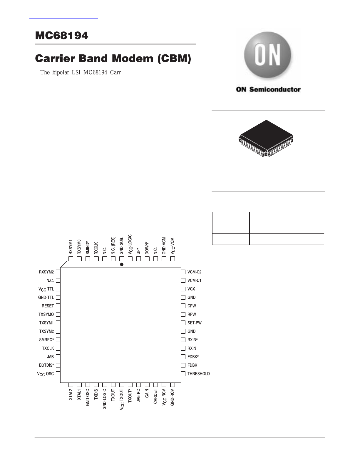
PIN ASSIGNMENTS AND DEVICE MARKING
http://onsemi.com
CERQUAD
FJ SUFFIX
CASE 778B
ORDERING INFORMATION
Device Package Shipping
MC68194FJ CERQUAD 20 Units / Rail
765432152 51 50 49 48 47
8
9
10
11
12
13
14
15
16
17
18
19
20
21 22 23 24 25 26 27 28 29 30 31 32 33
MC68194FJ
AWLYYWW
A = Assembly Location
WL = Wafer Lot
YY = Year
WW = Work Week
MC68194FJR2 CERQUAD 450 Units / Reel
46
45
44
43
42
41
40
39
38
37
36
35
34
Semiconductor Components Industries, LLC, 1999
February , 2000 – Rev. 6
1 Publication Order Number:
MC68194/D

MC68194
TABLE OF CONTENTS
PAGE
SECTION 1 — GENERAL DESCRIPTION
1.1 TOKEN BUS LAN CARRIER BAND NODE OVERVIEW 3. . . . . . . . . . . . . . . . . . . . . . . . . . . . . . . . . . . . . .
1.2 CARRIER BAND MODULATION TECHNIQUE 3. . . . . . . . . . . . . . . . . . . . . . . . . . . . . . . . . . . . . . . . . . . . . .
1.3 MESSAGE (FRAME) FORMAT 4. . . . . . . . . . . . . . . . . . . . . . . . . . . . . . . . . . . . . . . . . . . . . . . . . . . . . . . . . . .
1.4 SYSTEM CONFIGURATION 4. . . . . . . . . . . . . . . . . . . . . . . . . . . . . . . . . . . . . . . . . . . . . . . . . . . . . . . . . . . . .
SECTION 2 — SIGNAL DESCRIPTION TABLE 6. . . . . . . . . . . . . . . . . . . . . . . . . . . . . . . . . . . . . . . . . . . . . . . . . . . . .
SECTION 3 — TRANSMITTER
3.1 OVERVIEW 8. . . . . . . . . . . . . . . . . . . . . . . . . . . . . . . . . . . . . . . . . . . . . . . . . . . . . . . . . . . . . . . . . . . . . . . . . . . .
3.2 TRANSMIT BUFFER 8. . . . . . . . . . . . . . . . . . . . . . . . . . . . . . . . . . . . . . . . . . . . . . . . . . . . . . . . . . . . . . . . . . . .
3.3 JABBER INHIBIT 9. . . . . . . . . . . . . . . . . . . . . . . . . . . . . . . . . . . . . . . . . . . . . . . . . . . . . . . . . . . . . . . . . . . . . . .
3.4 CLOCK GENERATOR 9. . . . . . . . . . . . . . . . . . . . . . . . . . . . . . . . . . . . . . . . . . . . . . . . . . . . . . . . . . . . . . . . . . .
3.4.1 Parallel–Resonant, Fundamental Mode Crystal 9. . . . . . . . . . . . . . . . . . . . . . . . . . . . . . . . . . . . . .
3.4.2 Parallel–Resonant, Overtone Mode Crystal 10. . . . . . . . . . . . . . . . . . . . . . . . . . . . . . . . . . . . . . . . .
3.4.3 External Clock Source 10. . . . . . . . . . . . . . . . . . . . . . . . . . . . . . . . . . . . . . . . . . . . . . . . . . . . . . . . . . .
SECTION 4 — RECEIVER AMPLIFIER/LIMITER WITH CARRIER DETECT
4.1 OVERVIEW 11. . . . . . . . . . . . . . . . . . . . . . . . . . . . . . . . . . . . . . . . . . . . . . . . . . . . . . . . . . . . . . . . . . . . . . . . . . .
4.2 AMPLIFIER 11. . . . . . . . . . . . . . . . . . . . . . . . . . . . . . . . . . . . . . . . . . . . . . . . . . . . . . . . . . . . . . . . . . . . . . . . . . .
4.3 CARRIER DETECT 11. . . . . . . . . . . . . . . . . . . . . . . . . . . . . . . . . . . . . . . . . . . . . . . . . . . . . . . . . . . . . . . . . . . .
SECTION 5 — CLOCK RECOVERY
5.1 OVERVIEW 12. . . . . . . . . . . . . . . . . . . . . . . . . . . . . . . . . . . . . . . . . . . . . . . . . . . . . . . . . . . . . . . . . . . . . . . . . . .
5.2 ONE–SHOT 12. . . . . . . . . . . . . . . . . . . . . . . . . . . . . . . . . . . . . . . . . . . . . . . . . . . . . . . . . . . . . . . . . . . . . . . . . . .
5.3 PHASE–LOCKED LOOP (PLL) COMPONENTS 13. . . . . . . . . . . . . . . . . . . . . . . . . . . . . . . . . . . . . . . . . . .
5.3.1 Phase Detector (PD) 13. . . . . . . . . . . . . . . . . . . . . . . . . . . . . . . . . . . . . . . . . . . . . . . . . . . . . . . . . . . .
5.3.2 Voltage Controlled Multivibrator (VCM) 13. . . . . . . . . . . . . . . . . . . . . . . . . . . . . . . . . . . . . . . . . . . . .
5.3.3 Loop Filter 13. . . . . . . . . . . . . . . . . . . . . . . . . . . . . . . . . . . . . . . . . . . . . . . . . . . . . . . . . . . . . . . . . . . . .
5.3.4 Loop Characteristics 14. . . . . . . . . . . . . . . . . . . . . . . . . . . . . . . . . . . . . . . . . . . . . . . . . . . . . . . . . . . .
SECTION 6 — DATA RECOVERY
6.1 OVERVIEW 14. . . . . . . . . . . . . . . . . . . . . . . . . . . . . . . . . . . . . . . . . . . . . . . . . . . . . . . . . . . . . . . . . . . . . . . . . . .
6.2 RECEIVER END–OF–TRANSMISSION BLANKING 15. . . . . . . . . . . . . . . . . . . . . . . . . . . . . . . . . . . . . . . .
SECTION 7 — SERIAL INTERF ACE
7.1 OVERVIEW 16. . . . . . . . . . . . . . . . . . . . . . . . . . . . . . . . . . . . . . . . . . . . . . . . . . . . . . . . . . . . . . . . . . . . . . . . . . .
7.2 PHYSICAL DA TA REQUEST CHANNEL 16. . . . . . . . . . . . . . . . . . . . . . . . . . . . . . . . . . . . . . . . . . . . . . . . . .
7.2.1 TXCLK — Transmit Clock 16. . . . . . . . . . . . . . . . . . . . . . . . . . . . . . . . . . . . . . . . . . . . . . . . . . . . . . . .
7.2.2 SMREQ* — Station Management Request 16. . . . . . . . . . . . . . . . . . . . . . . . . . . . . . . . . . . . . . . . .
7.2.3 TXSYM0, TXSYM1, and TXSYM2 — Transmit Symbols 16. . . . . . . . . . . . . . . . . . . . . . . . . . . . .
7.3 PHYSICAL DATA INDICATION CHANNEL 16. . . . . . . . . . . . . . . . . . . . . . . . . . . . . . . . . . . . . . . . . . . . . . . .
7.3.1 RXCLK — Receive Clock 16. . . . . . . . . . . . . . . . . . . . . . . . . . . . . . . . . . . . . . . . . . . . . . . . . . . . . . . .
7.3.2 SMIND* — Station Management Indication 16. . . . . . . . . . . . . . . . . . . . . . . . . . . . . . . . . . . . . . . . .
7.3.3 RXSYM0, RXSYM1, and RXSYM2 — Receive Symbols 16. . . . . . . . . . . . . . . . . . . . . . . . . . . . .
SECTION 8 — PHYSICAL MANAGEMENT
8.1 OVERVIEW 17. . . . . . . . . . . . . . . . . . . . . . . . . . . . . . . . . . . . . . . . . . . . . . . . . . . . . . . . . . . . . . . . . . . . . . . . . . .
8.2 RESET 17. . . . . . . . . . . . . . . . . . . . . . . . . . . . . . . . . . . . . . . . . . . . . . . . . . . . . . . . . . . . . . . . . . . . . . . . . . . . . . .
8.3 INTERNAL LOOPBACK 17. . . . . . . . . . . . . . . . . . . . . . . . . . . . . . . . . . . . . . . . . . . . . . . . . . . . . . . . . . . . . . . .
8.4 ST ANDARD OPERATION 17. . . . . . . . . . . . . . . . . . . . . . . . . . . . . . . . . . . . . . . . . . . . . . . . . . . . . . . . . . . . . . .
8.5 IDLE 17. . . . . . . . . . . . . . . . . . . . . . . . . . . . . . . . . . . . . . . . . . . . . . . . . . . . . . . . . . . . . . . . . . . . . . . . . . . . . . . . .
8.6 COMMAND RESPONSE TIMING 17. . . . . . . . . . . . . . . . . . . . . . . . . . . . . . . . . . . . . . . . . . . . . . . . . . . . . . . .
SECTION 9 — ELECTRICAL SPECIFICATIONS TABLES 20. . . . . . . . . . . . . . . . . . . . . . . . . . . . . . . . . . . . . . . . . . .
http://onsemi.com
2
MC68194
SECTION 1
GENERAL DESCRIPTION
1.1 TOKEN BUS LAN CARRIER BAND NODE OVERVIEW
The MC68194 Carrier Band Modem (CBM) is part of ON
Semiconductor’s solution for an IEEE 802.4 token bus
carrier band Local Area Network (LAN) node. The CBM
integrates the function of the single–channel,
phase–coherent Frequency Shift Keying (FSK) physical
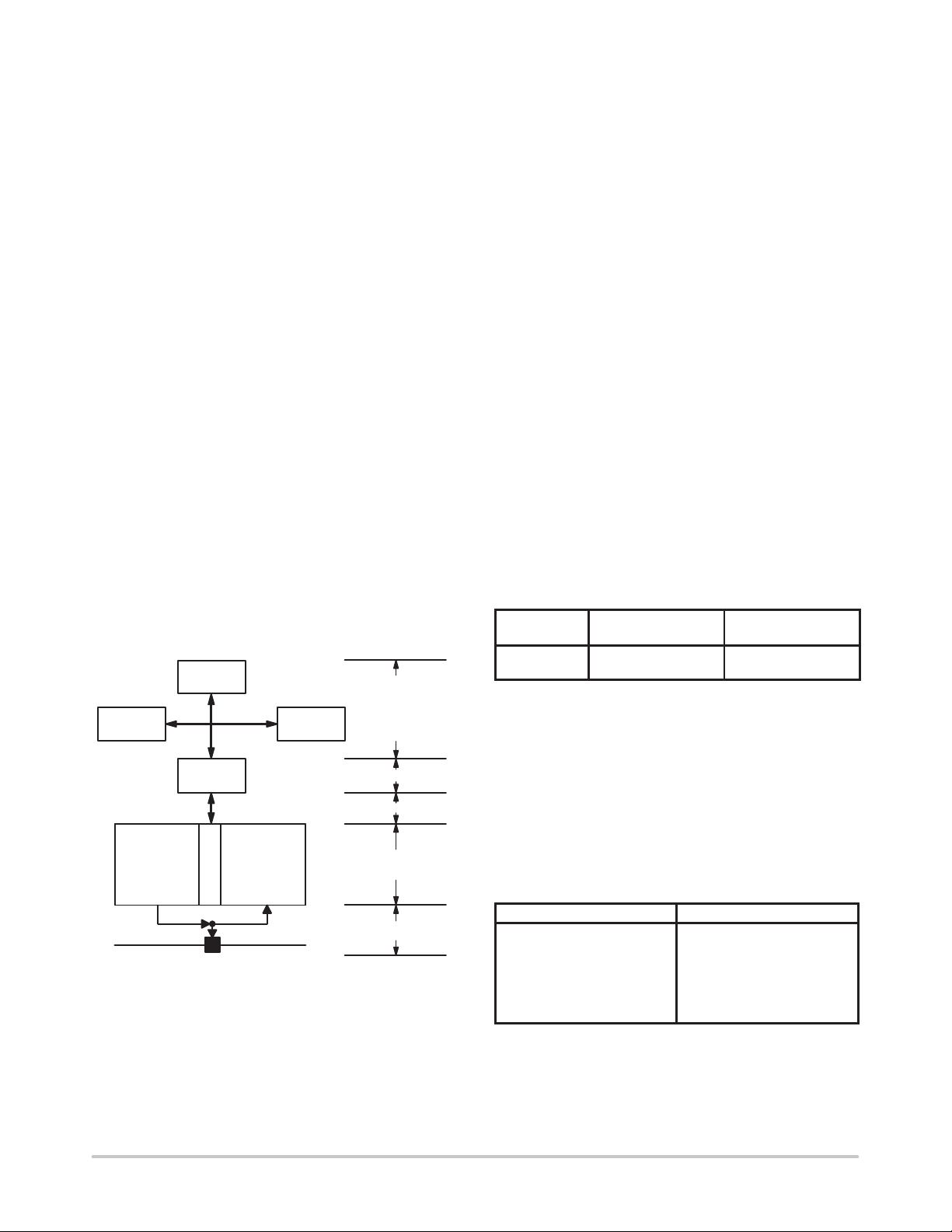
layer. Figure 1–1 illustrates the architecture of a token bus
LAN node as commonly used in Manufacturing Automation
Protocol (MAP) industrial communications. Based on the
ISO–OSI model, the LLC Sublayer and additional upper
layers are typically supported by a local MPU subsystem,
while the IEEE 802.4 token bus MAC Sublayer and Physical
Layer are implemented by the MC68824 Token Bus
Controller (TBC) and MC68194 CBM respectively .
The MC68194 provides the three basic functions of the
physical layer including data transmission to the coax cable,
data reception from the cable, and management of the
physical layer. For standard data mode (also called MAC
mode), the carrier band modem receives a serial transmit
data stream from the MC68824 TBC (called symbols or
atomic symbols), encodes, modulates the carrier, and
transmits the signal to the coaxial cable. Also in the data
mode, the CBM receives a signal from the cable,
demodulates the signal, recovers the data, and sends the
received data symbols to the TBC. Communication between
the TBC and CBM is through a standardized serial interface
inconsistent with the IEEE 802.4 DTE–DCE serial
interface.
MC68000
SYSTEM BUS
INTERFACE
MODULATOR
TRANSMITTER
/
PROCESSOR
TOKEN BUS
CONTROLLER
S
T
DEMODULATOR
A
T
M
I
G
O
M
N
T
MEMORY
/
RECEIVER
TOKEN BUS COAX
LLC
&
UPPER
LAYERS
MAC SUB–LAYER
SERIAL INTERFACE
PHYSICAL
LAYER
MEDIA LAYER
Figure 1–1. IEEE 802.4 T oken Bus Carrier Band Node
The physical layer management provides the ability to
reset the CBM, control the transmitter, and do loopback
testing. Also, an onboard RC timer provides a “jabber”
inhibit function to turn off the transmitter and report an error
condition if the transmitter has been continuously on for too
long. Similar to the data mode, the CBM management mode
makes use of the TBC serial interface.
1.2 CARRIER BAND MODULATION TECHNIQUE
The CBM uses phase–coherent frequency shift keying
(FSK) modulation on a single channel system. In this
modulation technique, the two signaling frequencies are
integrally related to the data rate, and transitions between the
two signaling frequencies are made at zero crossings of the
carrier waveform. Figure 1–2 shows the data rate and
signaling frequencies. An {L} is represented as one half
cycle of a signal, starting and ending with a nominal zero
amplitude, whose period is equal to the period of the data
rate, with the phase of one half cycle changing at each
successive {L}. An {H} is represented as one full cycle of
a signal, starting and ending with a nominal zero amplitude
whose period is equal to half the period of the data rate. In
a 5 Mbps implementation, the frequency of {L} is 5.0 MHz
and for {H} is 10 MHz. For a 10 Mbps implementation, the
frequency of {L} is 10 MHz and for {H} is 20 MHz. The
other possible physical symbol is when no signal occurs for
a period equal to one half of the period of the data rate. This
condition is represented by {off}.
Data Rate
MBPS
5
10
Figure 1–2. Data Rate versus Signaling Frequencies
Frequency of Lower
Tone MHz {L}
5.0
10
Frequency of Higher
Tone MHz {H}
10
20
The specified physical symbols ({L}, {H} and {off}) are
combined into pairs which are called MAC–symbols. The
MAC–symbols are transferred across the serial link. The
encodings for the five MAC–symbols are shown in Figure
1–3. Figure 1–4 shows the phase coherent FSK modulation
scheme for ONE, ZERO, and NON–DA T A. The IEEE 802.4
document does not specify the polarity used to transmit data
on the physical cable. The receiver must operate without
respect to polarity.
Mac–Symbol Encoding
Silence
Pad–Idle Pairs
Zero
One
Non–Data
ND1
ND2
{off off}
{L L} {H H}
{H H}
{L L}
{H L}
{L H}
http://onsemi.com
3

MC68194
Figure 1–3. MAC Symbol Encoding
ONE
LL
L
LH
ND1
1 BIT TIME =
ZERO
H
H
Figure 1–4. Phase–Coherent Modulation Scheme
1.3 MESSAGE (FRAME) FORMAT
1/ BIT RATE
H
ND2
1 BIT TIME
Although the CBM only uses MAC symbols
one–at–a–time, the MAC or TBC is responsible for
combining the above defined MAC symbols into messages
(more correctly called frames). For the purposes of the
CBM, a simplified frame format can be used consisting of:
SILENCE || PAD–IDLE | START DELIMITER | DATA | END
DELIMITER || SILENCE
where:
PAD–IDLE =
alternating {LL} {HH} pairs which must
occur in octets or groups of eight symbols. Pad–idle provides a training signal
for the receiver and occurs at the beginning of every transmission (and between
frames in a multiple frame transmission).
ST ART
DELIMITER
=
a unique pattern of eight symbols (one octet) that marks the beginning of a frame.
The pattern is:
ND1 ND2 0 ND1 ND2 0 0 0
where ND1 is the first symbol transmitted.
DATA =
octets of ZERO/ONE patterns that are the
actual data or “information” contained
within the frame.
END
DELIMITER
=
a unique pattern of symbols that marks
the end of a frame. The pattern is:
ND1 ND2 1 ND1 ND2 1 {I=0/1} {0/1}
where ND1 is the first symbol transmitted. Note that unlike the Start Delimiter, the last two bits of the End Delimiter
octet are not always the same. The
seventh bit of the octet is called the I Bit
or Intermediate bit which = 1 when there
is more to transmit and = 0 at the end of
a transmission.
A single transmission can consist of one or more frames.
In a multi–frame transmission, Pad–Idle is sent between
consecutive frames to separate them. If an End Delimiter
occurs within a multi–frame transmission its I Bit will = 1,
and the last end delimiter will have its I Bit = 0.
The CBM accepts a stream of MAC symbols from the
TBC and modulates the phase–coherent transmit signal
accordingly. Conversely, the CBM receives a
phase–coherent signal stream from the cable, decodes the
MAC symbols, and reports them. On transmission there is
NON-DATA PAIR
a direct one–to–one correlation between MAC symbols
requested and the modulated signal; however, during
reception exceptions can occur. The CBM is allowed to
report Silence or the actual Zero/One pattern during
preamble which is done to allow the receiver to “train” to the
incoming signal. Also, if noise in the system has corrupted
the data, it may show up as an incorrect MAC symbol or the
CBM can report a BAD SIGNAL symbol if an incorrect
combination of ND symbols is detected (ND2 without an
ND1, ND2 followed by ND2, etc.)
1.4 SYSTEM CONFIGURATION
Figure 1–5 illustrates the CBM and peripheral circuitry
required for an IEEE 802.4 carrierband 5 Mbps or 10 Mbps
data rate phase–coherent FSK physical layer. The CBM
communicates with the MAC or TBC through a TTL
compatible serial interface that is consistent with the IEEE
802.4 exposed DTE–DCE interface. Management and
transmission symbol requests are accepted via the CBM
physical data request channel (TXSYM0–TXSYM2,
SMREQ*, and TXCLK). The physical data indication
channel (RXSYM0–RXSYM2, SMIND*, and RXCLK) is
used to send received symbols and management responses
to the MAC.
The periphery circuitry is primarily associated with
interface to the LAN coaxial cable and data recovery. An
external crystal or clock source is required (20 MHz for 5
Mbps data rate or 40 MHz for 10 Mbps data rate) for onboard
timing and transmit clock. Also, an RC timing network sets
the jabber timeout period.
The coaxial cable interface combines the transmit and
receive signal functions. For transmission, the CBM provides
differential drive signals (TXOUT and TXOUT*) whose
signaling is ECL levels referenced to VCC (logic high
+4.1 V , logic low [ + 3.3 V) and a gate signal called TXDIS.
The IEEE 802.4 standard puts specific requirements on the
signal transmitted to the cable:
Between +63 dB and +66 dB (1.0 mV, 75 Ω) [dBmV]
output voltage level.
Transmitter–off leakage not to exceed –20 dB
(1.0 mV, 75 Ω) [dBmV].
Signal transition time window (eye pattern)
dependent on data rate.
Because of this, an external amplifier with waveshaping
is required. The CBM TXOUT/TXOUT* outputs provide
complementary signals with virtually no slew, and the
TXDIS is an enable signal helpful for turning the external
amp off “hard” to meet the low level leakage.
[
http://onsemi.com
4

MC68194
AMPLIFICATI
On the reception side, the CBM requires a pre–amplifier
to receive the low level signal from the cable. The signal
available at the “F”–connector can range from +10 dB to +66
dB (1.0 mV , 75 Ω) [dBmV]. The signal required at the CBM
is about 12 dB above this (net gain through the transformer,
pre–amp, and any filtering). The receiver can be used in full
differential or single–ended mode.
A second part of the receiver function is the signal detect
or carrier detect function. The IEEE 802.4 requires that the
receiver detect a signal of +10 dBmV or above (i.e., be
turned “on”) and report Silence for a signal of +4.0 dBmV
RESET
SMREQ*
TXSYM2
TXSYM1
TXSYM0
TXCLK
SMIND*
RXSYM2
RXSYM1
RXSYM0
EOTDIS*
RXCLK
XTAL1
XTAL2
INTERFACE
DECODER
BUFFER
GENERATOR
SM MODE
BUFFER
SERIAL
OUTPUT
CLOCK
MUX
DAT A COMMANDS
STATION
MANAGEMENT
COMMANDS
PHYSICAL
MANAGEMENT
RECEIVE
DEMODULATOR
TRANSMIT
MODULATOR
LOOPBACK
RECEIVE
MUX
ONE SHOT
RECOVERY
SYNCHRONIZE
AND SQUELCH
CLOCK
AND
or below (i.e., be turned “off”). Therefore, a 6.0 dB (2:1
voltage ratio) range or window is defined in which the signal
detect must switch. The CBM is optimized for this range
(including the pre–amp gain), although it is trimmed via an
external THRESHOLD.
The remaining external components are associated with
clock recovery. A capacitor and resistor (internal R also
provided) set one–shot timing, and an active filter for a PLL
used in clock and data recovery is required. The active filter
can be implemented via an op amp, or if 5.0 volt operation
is required, an alternate charge pump design can be used.
ON
AND
WAVESHAPING
F–CONNECTOR
RECEIVE
PRE–AMP
BUFFER
JABBER
CONTROL
RECEIVE
AMPLIFIER
CARRIER
DETECT
TXDIS
JAB–RC
FDBK*
RXIN
RXIN*
FDBK
TXOUT
TXOUT*
V
CC
JAB
THRESHOLD
GAIN
CARDET
CPW RPW
+5 V
VCM–C1
SET–PW
Figure 1–5. Functional Block Diagram
The clock recovery and data decoder is a synchronous
design which provides superior performance minimizing
clock jitter.
Although primarily intended for the IEEE 802.4 carrier
band, the CBM is also an excellent device for point–to–point
http://onsemi.com
D* U* VCX
PLL
FILTER
data links, fiberoptic modems, and proprietary LANs. The
MC68194 can be used over a wide range of frequencies and
interfaces easily into different kinds of media.
5

MC68194
SECTION 2
SIGNAL DESCRIPTION
Symbol T ype Name/Description
TXSYM0–TXSYM2 TTL/I* TRANSMIT SYMBOLS — These TTL inputs are request channel signals used to send
either serial transmission symbols in the MAC mode or commands in station
management mode. They are synchronized to TXCLK and are normally connected to
the TXSYMX outputs of the MC68824. SMREQ* selects the meaning of these signals
as either MAC mode or management mode.
SMREQ* TTL/I* STATION MANAGEMENT REQUEST — A TTL input that selects the mode of the
request channel signals TXSYMX. Synchronized to TXCLK, SMREQ* is equal to one
for MAC mode and equal to zero for management mode. It is normally driven by the
SMREQ* output of the MC68824.
TXCLK TTL/O TRANSMIT CLOCK — A TTL clock output generated from the crystal oscillator (it is 1/4
of the oscillator frequency) used to receive request channel symbols from the MC68824.
TXCLK is equal to the data rate of the application (5.0 MHz or 10 MHz for IEEE 802.4).
TXSYMX and SMREQ* are synchronized to the positive edge of TXCLK which is
supplied to the MC68824.
RXSYM0–RXSYM2 TTL/O RECEIVE SYMBOLS — These TTL outputs are indication channel signals used to
provide either serial receive symbols in MAC mode or command confirmation/indication
in station management mode. They are synchronized to RXCLK and are normally
connected to the RXSYMX inputs of the MC68824. SMIND* selects the meaning of
these signals as either MAC mode or management mode.
SMIND* TTL/O STA TION MANAGEMENT INDICA TION — A TTL output that indicates the mode of the
CBM and RXSYMX lines. Synchronized to RXCLK, SMIND* is equal to one for MAC
mode and equal to zero for management mode. It is normally connected to the SMIND*
input of the MC68824.
RXCLK TTL/O RECEIVE CLOCK — A TTL clock output used to send indication channel symbols to
the MC68824. Its frequency is nominally equal to the data rate (5.0 MHz or 10 MHz for
IEEE 802.4). RXCLK is generated from a PLL that is locked to the local oscillator during
loopback, station management, or the absence of received data. During frame reception
the PLL is locked to the incoming received data. RXSYMX and SMIND* are
synchronized to negative edge of RXCLK.
EOTDIS* TTL/I* END–OF–TRANSMISSION DISABLE — When low, this TTL input disables the
end–of–transmission receiver blanking required by the IEEE 802.4 Spec, Section
12.7.6.3. When high the blanking works in accordance with the spec requirements.
TXOUT,TXOUT* ECL/O TRANSMIT OUTPUTS — A differential output signal pair (MECL level referenced to
VCC) used to drive the transmitter circuitry . The silence or “off” state is both outputs one
(high). The output data stream is phase–coherent FSK encoded.
TXDIS OC TRANSMIT DISABLE — An open collector output used to disable transmitter circuitry .
This output is high when the transmitter is off (TXOUT and TXOUT* both high).
JAB TTL/O JABBER — A TTL output signal generated from the jabber–inhibit timer. When equal
to one, JAB indicates the timer has timed–out and an error has occurred.
RESET TTL/I* RESET — A TTL input signal that when high asynchronously resets the CBM.
*All TTL inputs include a 15 kΩ pullup resistor to VCC.
http://onsemi.com
6

MC68194
Signal Description (Cont.)
Symbol Type Name/Description
RXIN, RXIN* I RECEIVER INPUTS — A differential input signal pair for the receiver amplifier/limiter.
These inputs may be used differentially or single ended.
FDBK, FDBK* DC FEEDBACK BYPASS — These two points are provided to bypass dc feedback
around the receiver amplifier.
THRESHOLD I THRESHOLD ADJUST — The receiver threshold detect is trimmed with this pin.
GAIN O GAIN — This output can be used to monitor the receiver amplifier output signal. Used
only for test purposes.
CARDET O CARRIER DETECT — This output can be used to filter the internal signal that is
sampled to sense carrier detect.
RPW, CPW I PULSE–WIDTH RESISTOR/CAPACITOR — A resistor and capacitor set a one–shot
pulse width used in the clock recovery circuitry.
SET–PW O PULSE WIDTH TEST POINT — Output test point used for adjusting clock recovery
one–shot pulse width.
UP*, DOWN* ECL/O PLL PHASE DETECTOR OUTPUTS — UP* and DOWN* are the pump–up and
pump–down outputs, respectively, of the PLL digital phase detector. They are MECL
levels referenced to +5.0 volts and are used to drive inputs to an active filter or charge
pump for the PLL.
VCX I VCM CONTROL — The control voltage applied to the PLL voltage controlled
multivibrator.
VCM–C1, VCM–C2 I VCM CAPACITOR — VCM capacitor inputs. VCM frequency is 4X RXCLK.
JAB–RC I JABBER–INHIBIT RC — A resistor–capacitor network connected to this pin sets the
jabber–inhibit time constant.
XTAL,1 XTAL2 I CLOCK CRYSTAL — Oscillator circuit inputs may be used with a crystal or an external
clock source. Oscillator frequency is 4X data rate.
VCC–VCM VCM POWER — 5.0 ± 5% volts for VCM.
VCC–TXOUT TXOUT POWER — 5.0 ± 5% volts for TXOUT/TXOUT*.
VCC–OSC OSCILLATOR POWER — 5.0 ± 5% volts for oscillator.
VCC–RCV RECEIVER POWER — 5.0 ± 5% volts for receiver amplifier/limiter.
V
CC
VCC–TTL TTL POWER — 5.0 ± 5% volts for TTL output buffers.
GND–TTL, GND–VCM,
GND–LOGIC, GND–OSC,
GND–RCV, GND–SUBS, GND
LOGIC POWER — 5.0 ± 5% volts for remaining logic.
GROUND — Reference voltage for TTL buffers, VCM, internal logic, oscillator, receiver/
limiter, substrate respectively. Two additional grounds are used to isolate signals.
http://onsemi.com
7
MC68194
SECTION 3
TRANSMITTER
3.1 OVERVIEW
The transmitter function includes the serial interface
decoder, transmit modulator , transmit buffer , jabber inhibit,
and clock generator. (Although the clock generator is not
used exclusively by the transmit function, the generator will
be discussed here.) The MC68194 receives request channel
symbols on the TXSYMX pins which are synchronized to
TXCLK. As is described in the Serial Interface discussion,
MAC transmit symbols are input serially (CBM in MAC
mode), decoded, and used to modulate an output signal. The
Serial Interface Decoder is used both for MAC mode to
decode data transmit commands (symbols) and
management mode to decode management commands. The
decoded transmit commands or symbols are used by the
Transmit Modulator to generate phase–coherent signaling
as discussed in the CBM General Description. The transmit
buffer receives the modulated signal and drives differential
output signals.
The clock generator provides TXCLK and internal clocks
of 2 times (2X) and 4 times (4X) TXCLK. The 4X clock is
actually the oscillator frequency. These clocks are used to
receive the TX symbols and generate the modulated signal.
3.2 TRANSMIT BUFFER
The modulated transmit data stream drives the TXOUT
and TXOUT* pins of the MC68194. These pins are
complementary outputs with closely matched edge
transitions. This is useful in helping meet the IEEE 802.4
carrierband requirement for a transmit jitter of less than
"
1% of the data rate. TXOUT and TXOUT* are generally
used to drive a differential amplifier which is used to achieve
the necessary output level at the cable and meet the rise/fall
time window (or “eye” pattern) of the IEEE 802.4. A third
output called TXDIS is available to gate the amplifier
circuitry on or off.
The TXTOUT and TXTOUT* have ECL levels
referenced to VCC (Figure 3–1). Levels are typically 4.11 V
for a high and 3.25 for a low. Pulldown resistors are required
with the outputs specified to drive a maximum load of 220
Ω to ground reference.
Operation of the transmit outputs is controlled in the
following manner:
1. Management mode — The TX outputs are always
disabled while the CBM is in management mode. When
leaving management mode the TX outputs remain
disabled if a RESET command has been issued and an
ENABLE TRANSMITTER and DISABLE
LOOPBACK commands have not been issued.
Resetting the CBM enables internal loopback and
disables the transmitter .
2. MAC (data) mode — After leaving management mode,
the CBM can function in internal loopback (for test) with
the transmitter disabled, out of loopback with transmitter
disabled (receive only), or in standard data mode with the
TX outputs controlled by the modulator.
TXDIS
VCC–TXOUT
TXOUT
RP
TX AMP
TXOUT*
RP
Figure 3–1. Transmitter Outputs
3. Jabber inhibit activated — If the jabber inhibit fires, it
forces the CBM into management mode and disables the
TX outputs. This condition can only be cleared by a reset
condition.
The TXDIS output is an open collector switched current
source. TXDIS sinks a nominal 0.5 mA when the
TXOUT/TXOUT* outputs are enabled. TXDIS is off or
high impedance when the transmitter is disabled.
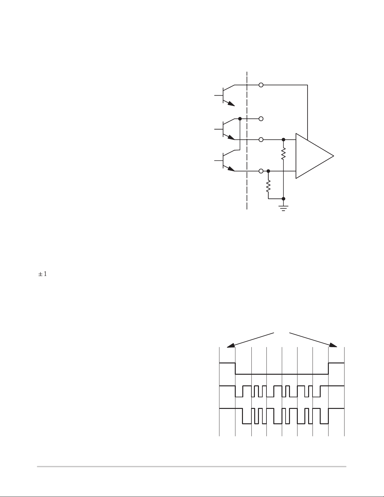
The signaling on the TX outputs and TXDIS is shown in
Figure 3–2. The “off” or silence condition is both TXOUT
outputs high and TXDIS also high. The figure shows an
example of the signal pattern for both leaving and entering
a silence condition.
SILENCE
0
TXDIS
TXOUT
TXOUT*
Figure 3–2. Transmitter Output Signaling
11 ND1 ND21
OFFOFF
http://onsemi.com
8

MC68194
3.3 JABBER INHIBIT
The jabber inhibit function prevents the transmitter from
transmitting indefinitely . An external resistor and capacitor
pair tied to the CBM JAB–RC pin set the maximum time that
the transmitter is allowed to transmit. When transmission is
attempted for a period longer than the specified time, the
jabber inhibit function forces the transmitter to shut down
and alerts the system that this has been done by generating
a PHYSICAL ERROR indication on the serial interface
indication channel. The error indication is removed only
after a reset has occurred on the RESET pin or after a RESET
command has been received on the station management
interface. The ENABLE TRANSMITTER and DISABLE
LOOPBACK commands can then be used to re–enable the
transmitter outputs. While the PHYSICAL ERROR
indication is present, the normally–low JAB pin of the
MC68194 will be high. This TTL output may be used to turn
off external transmitter circuitry or an isolation relay.
A block diagram of the jabber inhibit function is shown in
Figure 3–3. When edges are present on the TXDATA line,
the jabber capacitor is allowed to charge. When the
transmitter stops transmitting, the capacitor is discharged.
The circuit looks for any edges in the previous 16 TXCLKs
before deciding whether to charge or discharge the
capacitor. When the capacitor voltage reaches the reference
threshold, the comparator switches and the jabber output is
latched. The jabber output is fed back internally and disables
the transmitter. This signal is also brought out to the JAB pin
for use in disabling external transmitter circuitry.
For the IEEE 802.4 spec, the jabber timeout must be 0.5
sec ± 25%. An RC time constant of 265 millisec. will give
about a 0.5 sec timeout. The maximum resistor size is 125
kΩ. Components should be 10% tolerance or better.
Common values are R = 120 kΩ and C = 2.2 µF.
3.4 CLOCK GENERATOR
The clock generator is used to generate all of the transmit
timing, TXCLK, and internal CBM timing for station
management and loopback. The generator consists of a
crystal oscillator/buffer that drives B2 and B4 stages. The
oscillator frequency must be four times (4X) the serial data
rate. As an example, the IEEE 802.4 5 Mbps carrier band
(TXCLK = 5.0 MHz) requires an oscillator frequency of 20
MHz. The basic circuit is a single transistor Colpitts
oscillator as shown in Figure 3–4.
The oscillator is used in one of three modes depending on
the data rate and the application:
1. With a parallel–resonant, fundamental mode crystal.
2. With a parallel–resonant, overtone mode crystal.
3. With an external clock source.
The fundamental mode can typically be used up to
frequencies of about 20 MHz; this is crystal dependent and
some crystal types can be used as high as 40 MHz. Beyond
the fundamental mode upper limit, an overtone mode crystal
is used. An alternative to a crystal is an external clock source
such as an integrated crystal clock to drive the CBM.
3.4.1 Parallel–Resonant, Fundamental Mode Crystal
Figure 3–4 shows the external crystal and capacitors C1
and C2 used for fundamental mode operation. The crystal
must be parallel resonant with a maximum series resistance
of 30 Ω.
This configuration is normally used for the IEEE 802.4
5 Mbps carrierband standard. The required transmit
frequency stability is ± 100 ppm (0.01%). It is suggested that
a crystal with a total frequency tolerance (calibration
tolerance, temperature variation, plus aging) of ± 50 ppm to
± 60 ppm be used. The remaining frequency budget is
reserved for the CBM and other components over
temperature and power supply variation.
The series combination of C1 and C2 should be equal to
the specified crystal load (typically 20 pF or 32 pF).
Additionally, C1 and C2 should be large enough to swamp
out the CBM device capacitance. The XTAL1 input
capacitance is typically 1.5 pF to 2.0 pF, and C1 should be
at least an order of magnitude greater (C1 > 20 pF). Also, C1
must be greater than the crystal load capacitance because of
the series combination of C1 and C2. Generally the ratio
C1:C2 is from 1:1 to 3:1.
+ 5 V
D
TXDATA
DELAY
TXCLK ONE OF 16
V
CC
Q
D
CLK
R
CLK
Figure 3–3. Jabber Inhibit Block Diagram
R JAB
JAB RC
PIN
Q
PHYSICAL MANAGEMENT
OR HARDWARE RESET
http://onsemi.com
C JAB
+
–
V REF
9
+ 5V
D
CLK
R
JAB PIN
Q
INTERNAL
JABBER INHIBIT

MC68194
For a 20 pF crystal load:
20 pF = C1C2/(C1 + C2)
and
C2 = 20 pF [C1/(C1 – 20 pF)]
T ypical values are C1 = 60 pF and C2 = 30 pF.
It is suggested that best results will be had with close
tolerance (5%) NPO ceramic capacitors — trimming should
not be required. If trimming is necessary, a third trimming
capacitor C3 can be placed in series with the crystal.
Capacitors C1 and C2 will have to be increased in value
because the crystal load now becomes C1 and C2 and C3 in
series. For help in designing the capacitor network the user
is directed to Design of Crystal and Other Harmonic
Oscillators, B. Parzen, Wiley, 1983.
3.4.2 Parallel–Resonant, Overtone Mode Crystal
Figure 3–4 also shows the network used for overtone
mode operation. The crystal is still parallel resonant, but
must be specified for overtone (harmonic) operation at the
desired frequency . A low series resistance of less than 30 Ω
is recommended.
VCC–OSC
CBM
20 kΩ
FUNDAMENTALOVERTONE
XTAL
L1
Figure 3–4. Crystal Oscillator Schematic Shows
C1
C2
C3
Configurations For Both Overtone and
Fundamental Modes
C1
C2
GND–OSC
XTAL1
XTAL2
Q1
TO
BUFFER
20 kΩ
800 µA
operating frequency the tank circuit impedance will appear
capacitive; therefore, the load to the crystal is C1 in series
with the capacitive reactance of the tank circuit.
This series combination should be equal to the desired
crystal load. Typically, C2 will increase in value as
compared to the fundamental mode situation because of the
cancelling effects of L1. Again the user is directed to the
above reference for optimum selection of components.
3.4.3 External Clock Source
Figure 3–5 shows the connection used for a TTL
compatible external clock source. XTAL1 and XTAL2 are
tied together defeating transistor Q1. External resistor R1 =
2.0 kΩ assures a high level greater than 3.0 V at an input
current of 800 µA. The TTL driver must be capable of
sinking 2.5 mA.
VCC–OSC
V
CC
TTL
CLOCK
OSC
Figure 3–5. TTL Compatible Clock Source Driving
2.5 mA
R1 = 2 kΩ
XTAL1
XTAL2
GND–OSC
CBM
20 kΩ
20 kΩ
Q1
CBM
TO
BUFFER
800 µA
The IEEE 802.4 for 5 Mbps or 10 Mbps data rate carrier
band requires a transmit frequency stability of ± 100 ppm
(0.01%). The external clock source must be specified for this
stability over temperature.
Inductor L1 and capacitor C2 form a tank circuit that is
parallel resonant at a frequency lower than the desired
crystal harmonic but above the next lower odd harmonic. C3
= 0.01 µF is a dc blocking capacitor to ground. At the
http://onsemi.com
10

MC68194
SECTION 4
RECEIVER AMPLIFIER/LIMITER WITH CARRIER DETECT
4.1 OVERVIEW
The IEEE 802.4 spec provides that the incoming signal
range for good signal is +10 dB (1.0 mV, 75 Ω) [dBmV] to
+66 dB (1.0 mV, 75 Ω) [dBmV] available at the modem
connector. The IEEE 802.4 further specifies that the modem
will report silence for any signal below +4.0 dB (1.0 mV, 75
Ω) [dBmV]. Therefore, the receiver function must amplify
any signal of +10 dBmV and above to limiting for good data
recovery , and the signal detect must switch within the +4.0
dBmV to +10 dBmV window, that is, it must be “off” for
+4.0 dBmV and below, and be “on” for +10 dBmV and
above. The MC68194 requires a pre–amplifier of about 12
dB in front of the onboard amplifier and carrier detect
function. Clock and data recovery are extracted from the
amplified/limited incoming signal, and the carrier detect is
used to control the clock and data recovery function based
on presence of good signal.
4.2 AMPLIFIER
Figure 4–1 shows a simple block diagram of the receiver
amplifier. Internally, dc feedback is used to bias the
amplifier, and connection points FDBK and FDBK* are
provided to ac bypass the feedback. With both receiver
inputs RXIN and RXIN* available, the device can be wired
either for differential or single–ended operation.
Differential is preferred for low noise.
FDBK
RR
RXIN*
RXIN
FDBK*
R
R = 7.5 kΩ (ALL RESISTORS OF EQUAL VALUE).
R
An external preamplifier with gain of about 12 dB is used
with the onboard amplifier. The pre–amp can drive the CBM
either single–ended or differentially . The onboard amplifier
output signal is used in two ways. One path adds an
additional limiter stage and is used to drive the clock and
data recovery stages. The second path is used to develop
carrier detect.
In the signal window where carrier detect must be active,
the internal amplifier remains in the linear (non–limiting)
range. Its output is fullwave rectified, and the rectified signal
is compared to an onboard threshold that is temperature and
voltage compensated. The rectified signal is also brought out
to an external lead called CARDET. A capacitor can be
added at this pin which combines with the series 125 Ω
resistor to form a low pass filter. This filtering is used to
knock any high frequency noise off of the signal. The output
of the comparator is a series of pulses (when the signal
amplitude is sufficiently large) which are digitally
integrated in the internal squelch signal.
4.3 CARRIER DETECTION THRESHOLD
The carrier detect threshold is internally generated and
compensated for power supply and temperature variation.
The THRESHOLD pin is provided to adjust the threshold
via an external resistor tied to VCC.
GAIN
125 Ω
OR
NOR
V
th
THRESHOLDCARDET
CARDET
CARDETS
V
CC
TO RXMUX
TO SQUELCH
PRE–AMP
FDBK
RXIN*
RXIN
FDBK*
(A) Receiver Used in Differential Mode
GAIN
OR
R
T
RR
V
th
R
R = 7.5 kΩ (ALL RESISTORS OF EQUAL VALUE).
Figure 4–1. Receiver Amplifier With Carrier Detect
R
(B) Receiver Used in Single–Ended Mode
http://onsemi.com
11
125 Ω
THRESHOLDCARDET
NOR
CARDET
CARDETS
V
CC
TO RXMUX
TO SQUELCH

SECTION 5 – CLOCK RECOVERY
SELEC
PAIR
5.1 OVERVIEW
The clock recovery circuitry is a key part of the receive
function providing RX clock, a 2 times (2X) RX clock, and
a 4 times (4X) RX clock for data recovery and to send
receive symbols to the MAC. Figure 5–1 is a simplified
functional schematic of the clock recovery logic. The clock
recovery is fed by the output stage of the receive amplifier.
The phase–coherent signal contains frequency components
equal to 1X and 2X the serial data rate. Figure 5–2 shows an
example of timing for a 5 Mb/s serial data rate. The RXOUT
signal drives a one–shot with a time period of 75% of 1/2 bit
time; this locks out edges caused by the higher frequency
component. The one–shot is non–retriggerable and is
triggered on both positive and negative going edges. This
produces a pulse for every edge of the lower frequency.
The output of the one–shot is divided by 2 to produce a
50% duty cycle signal equal in frequency to the lower
frequency of the phase–coherent signal. In turn, the B2
flip–flop output runs through a multiplexer to a
phase–locked loop (PLL) system. The multiplexer selects
the RXOUT signal when carrier detect is present; otherwise
the local oscillator divided by 4 is selected.
The PLL system consists of a digital phase detector, an
active loop filter, a voltage–controlled multivibrator
(VCM), and a divide–by–4 feedback counter. When in phase
lock, the output of the divide–by–4 feedback counter is
locked to the reference clock. In turn, the VCM 4 times clock
is also aligned with the reference clock as shown in Figure
5–2.
The 4 times clock from the VCM, the 2 times clock, and
the 1 times clock are all in phase (when the PLL is
phase–locked) with the reference clock, and are used to do
data recovery. Note that the reference clock can be 180 ° out
of phase with the bit time boundaries (Figure 5–2). This does
not affect the 2X and 4X clocks which are used to sample the
data. However, RXCLK can be out of sync with the bit time
boundaries and special circuitry in the data recovery logic
detects and corrects this condition.
When no valid input signal is available from the receive
amplifier (carrier detect is not asserted), the multiplexer
selects the local clock as a reference. This has the advantages
of:
1. Supply a RXCLK when no data is present.
2. Holding the PLL in frequency lock so that only
phase–lock must be achieved when switching to the RX
signal.
3. Providing a smooth transition for RXCLK when moving
from the local oscillator (at the beginning of a frame) and
vice versa (at the end of a frame). The PLL acts as an
integrator.
The IEEE 802.4 provides a P AD–IDLE or training signal
at the beginning of any transmission. The PAD–IDLE for
phase–coherent FSK is an alternating one and zero pattern,
and the PLL is capable of being locked–in well within the 24
MC68194
bit times (3 octets). The design goal is to be locked–in within
12–16 bit times. Data recovered during this lockup time at
the
Figure 5–1. Clock Recovery Logic
beginning of a transmission can be invalid because the PLL
clocks are not sync’ed. As a result the data recovery logic
forces silence for 17–18 bit times after the carrier detect
switches the reference clock (via the multiplexer) at the
beginning of a received transmission.
5.2 ONE–SHOT
As previously stated, the one–shot is used to lock out the
transitions due to the higher frequency component of the
phase–coherent signal. The one–shot is non–retriggerable
and fires off both edges of the incoming RXOUT signal. The
time period should be set to 75% of half the bit time. As an
example, the 5 Mb/s data rate has a 200 nsec bit time and the
one–shot period then has a period of 75 nsec.
(4X BIT RATE)
T
LOCAL
OSC B 4
RXOUT
DATA
RECOVERY
ONE
SHOT
R
EXT
+ 5 V
RXOUT
75% OF 1/2
BIT TIME
ONE–SHOT
REF CLK
(B2)*
VCM
(IN LOCK)
*NOTE: Ref clock can also be 180° out of phase with bit time.
Figure 5–2. Clock Recovery Timing Signals
CPWRPW
C
EXT
BIT TIME
1/2
MUX
B
2
“1”
PD
SET
D*
–
PW
“0” “ND1”
B
4
U*
C1
OP
AMP
“1” “0” “ND2”
CBM
2X CLOCK
4X CLOCK
Q
VCM
C2
VCM
C
VCM
ACTIVE FILTER
ND
VCX
http://onsemi.com
12

MC68194
Figure 5–3 shows the arrangement of the external timing
capacitor and resistor. The internal resistor R
INT
may be
used with or without an external resistor. A test pin is also
provided (SET–PW) to monitor the pulse width.
For 5 Mbps operation, typically RPW = 1.5 kΩ and C
PW
=33 pF.
CBM
R
= 300 Ω
INT
SET–PW
NEEDED
ONLY
FOR
TEST
Figure 5–3. One–Shot Timing Components
5.3 PHASE–LOCKED LOOP (PLL) COMPONENTS
(TP)
PW
R
PW
R
EXT
600 mV
PW
+ 5 VC
C
EXT
The PLL consists of a digital phase detector (PD), an
active loop filter, a VCM, and a divide–by–4 feedback path.
Figure 5–4 shows the fundamental elements of the PLL with
their gain constants. The basic PLL allows the output
frequency ƒo to be “locked–on” to the input frequency ƒ
with a fixed phase relationship and to track it in frequency.
When “in lock” the inputs to the phase detector have zero
phase error. The input frequency is referenced to ƒo/4.
A PLL follows classic servo theory and equations. In the
following discussion a working knowledge of a PLL is
assumed. For more background and applications
information on PLL, the user is directed to Application Note
AN535.
∅i(s)
∅o(s)/4
DETECTOR
ƒo/4
PHASE
K
p
∅e(s)
B
K
FILTER
K
ƒ
4
n
VCM
K
o
∅o(s)
ƒ
∅e(s) = ( 1 / [ 1 + G(s) H(s)] ) ∅i(s)
∅o(s) = ( G(s) / [ G(s) H(s)] ) ∅i(s)
where:
G(s) = Kp Kƒ K
H(s) = Kn Kn = 1 / N = 1/4
o
Reference: App Note AN535
Figure 5–4. PLL Elements and Loop Equations
5.3.1 Phase Detector (PD)
The phase detector produces a voltage proportional to the
phase difference between ∅i(s) and ∅o(s)/4. This voltage
after filtering is used as the control signal for the VCM. The
PD has pump–up UP* and pump–down DOWN* outputs
with a typical 800 mV logic swing. UP* produces a low level
pulse equal in width to the amount of time the positive edge
of ∅i (REF CLOCK) leads the positive edge of ∅o/4
(VCM/4). DOWN* produces a low level pulse equal in
width to the amount of time the positive edge of ∅i lags
∅o/4. Both pulses will not occur on the same clock cycle as
∅o/4 must either lead or lag ∅i when the PLL is out of lock.
When in–lock, both outputs produce a very narrow pulse or
negative spike.
The gain of the phase detector is equal to (reference app
note AN532A):
Kp = (Logic swing)/2π = 800 mV/2π = 0.127 V/radian
5.3.2 V oltage Controlled Multivibrator (VCM)
The operating frequency range of the VCM is determined
by the capacitor tied to pins VCM–C1 and VCM–C2. The
capacitor should be selected to put the desired operating
frequency in the center of the VCM tuning range.
The transfer function of the VCM is given by:
Ko = Kv/s
where Kv is the sensitivity in radians per second per volt. K
is found by:
[(Upper frequency limit) – (Lower frequency limit)]2
Kv+
(Control voltage tuning range)
i
= 2π (nƒ)/nVCX rad/s/V
then
Ko = 2π (nƒ)/(nVCX)s rad/s/V
5.3.3 Loop Filter
Since a Type 2 system is required (phase coherent output,
see reference AN535), the loop transfer function of Figure
5–4 takes the form:
G(s) H(s) = [K (s+a)] / s
o
Writing the loop transfer function (from Figure 5–4) and
2
relating it to the above form:
G(s) H(s) = [KpKvKnKƒ] / s = [K (s+a)] / s
Having determined Kp, Ko, and that Kn = 1/4 then K
(filter transfer function) must take the form:
Kƒ = (s+a) / s
An active filter of the form shown in Figure 5–5A gives
the desired results, where:
Kƒ = (R2 C s+1) / R1 C s (for large A)
The active filter can also be implemented as shown in
Figure 5–5B using an alternate approach of a charge pump.
The advantage of the charge pump design is that it can be
implemented using only a single 5.0 volt supply . Its transfer
function is:
v
p
2
ƒ
http://onsemi.com
13

MC68194
S
CR
Kƒ = (RC s +1) / C s
R
UP*
DN*
R
PULLDOWN
Figure 5–5A. Active Filter Using Op Amp
1
R
PULLDOWN
R
V
CC
MPSH81
Figure 5–5B. Charge Pump/Filter
1
FILTER
2
2
–
3
+
R
2
C
UP*
C
LOWPASS
R
5.3.4 Loop Characteristics
If an active filter as shown with an op amp is used, the
V
DD
7
A
4
6
R
LOWPASS
VCX
C
LOWPAS
general PLL loop transfer function now becomes:
G(s) H(s) = Kp Kƒ Ko K
n
= Kp [(R2 C s+1) / R1 C s] (Kv/s) (1 / N)
Its characteristic equation is set to the form:
C.E. = 1 + G(s) H(s) = 0
= s2 + (Kp Kv R2) s / (R1 N) + Kp Kv) / (R1 C N)
Relating to the standard form (s2 + 2ξωns + ωn2) and
solving:
2
= (Kp Kv) / R1 C N 2ξωn = (Kp KvR2) / R1 N
ω
n
where
ωn = Natural frequency
ξ = damping factor.
If a change pump loop filter is used, the general PLL loop
MPSH81
MPS2369
DN
transfer function alternately becomes:
G(s) H(s) = Kp Kƒ Ko K
n
= Kp[(R C s + 1) / C s] (Kv / s) (1 / N)
Its characteristics equation is set to the form:
C.E. = 1 + (Gs) (Hs) = 0
= s2 + (Kp Kv R) s / (N) + (Kp Kv) / (C N)
C
Relating to the standard form (s2 + 2ξωns + ω
n
2
) and
solving:
VCX
2
= (Kp Kv) / C N 2ξωn = (Kp Kv R) / N
ω
n
SECTION 6 – DATA RECOVERY
6.1 OVERVIEW
The RXOUT signal from the receive amplifier and clocks
generated by the clock recovery logic are used by the data
recovery logic. The MC68194 recovers the data from the
encoded receive signal by opening sampling windows
around the 1/4 and 3/4 bit time positions and looking for
edges in the received signal (refer to Figure 6–1 for the
encoded data representations). A data ONE has transitions
only at the 0 and 1/2 bit time positions. A data ZERO has
transitions at the 0, 1/4, 1/2, and 3/4 bit time positions. A
NON–DA T A symbol has transitions at the 0, 1/4, and 1/2 bit
time positions (ND1) or at the 0, 1/2, and 3/4 bit time
positions (ND2). NON–DATA symbols should always
occur in pairs; each pair is made up of one of each type of
NON–DATA encoded symbols as shown in Figure 6–2
(ND1 followed by ND2).
BIT TIME
0.5
0 0.25
0.75
ONE
Figure 6–1. Encoded Data Representation
ZERO
ND1 ND2
ONEs, ZEROs, and NON–DATA pairs can be easily
decoded by keeping track of the 1/4 and 3/4 bit time position
transitions. The ONEs, ZEROs, and NON–DATA pairs are
then reported on the RXSYMX pins as described in the serial
interface discussion. Two other conditions can also be
reported while receiving in MAC mode — BAD SIGNAL
and SILENCE. BAD SIGNAL is reported when a ND1
symbol is not followed immediately by a ND2 symbol or
when a ND2 symbol is received and not immediately
preceded by a ND1 symbol.
SILENCE is reported when one of four conditions occurs:
1. When the amplitude of the received signal is not large
enough to trigger the on–chip carrier detect circuit.
Reporting SILENCE when the carrier detect signal is not
asserted prevents the chip from responding to low level
noise.
2. When in internal loopback mode and SILENCE is being
requested on the TXSYMX pins, SILENCE will be
reported on the RXSYMX pins. An internal digital
carrier detect is used during loopback and this signal is
negated when SILENCE is requested on the request
channel.
3. During the PLL training period at the beginning of a
transmission. When an incoming signal first triggers the
http://onsemi.com
14

MC68194
carrier detect in the amplifier, the PLL must lock to the
new reference clock (generated from the data stream).
During the lockup time, recovered data may not be valid.
The data recovery logic forces SILENCE for a fixed
period of time (17–18 bit times).
4. During end–of–transmission blanking. See Section 6.2.
The P AD–IDLE at the beginning of a transmission is used
as a training signal as described in the clock recovery
section. After the PLL has achieved lock, the recovered
clock at this point may be in phase or 180° out of phase with
the bit time clock at the sending end. This creates a problem
for RXCLK and the data recovery logic because symbols
would be decoded as the wrong combination of 1/2 bit time
transitions.
Logic in the data recovery circuitry corrects for this
situation. If the clock is 180° out of phase, the PAD–IDLE
sequence (ONE, ZERO, ONE, ZERO, ONE, ...) will be
decoded as a sequence of NON–DATA symbols. Refer to
Figure 6–2. In normal data reception, NON–DA T A symbols
occur only in pairs; there are never three or more in a row.
Therefore, three or more NON–DA T A symbols occurring in
a row indicate that the bit time clock is 180° out of phase and
the bit time clock (RXCLK) must be slipped as shown in
Figure 6–3. The clock frequency and phase have now been
recovered and symbol decode proceeds as described below .
6.2 RECEIVER END–OF–TRANSMISSION BLANKING
The IEEE 802.4 requires that the physical layer recognize
the end of a transmission and report silence to the MAC for
a period thereafter. This period of silence is referred to as
blanking and must meet the following conditions:
1. Blanking must begin no later than 4 MAC–symbol times
after the last MAC–symbol of the End Delimiter (i.e., the
last End Delimiter of the transmission).
2. Blanking must continue to a point at least 24
MAC–symbol times but not more than 32 MAC–symbol
times from the last MAC–symbol of the End Delimiter.
The MC68194 provides this function by recognizing the
last End Delimiter of a transmission (I Bit = 0, see Section
1.3). The CBM reports silence for 32 symbols after the last
symbol of the End Delimiter.
The blanking function can be disabled for test purposes or
non–IEEE 802.4 applications via the EOTDIS* input.
G
PAD–IDLE
SEQUENCE
BIT TIME
CLOCK IN
PHASE
BIT TIME
CLOCK 180°
OUT OF
PHASE
ZERO ZERO
ND1
ONEONE
ND2ND2
Figure 6.2 Training Sequence Decoded With
In–Phase and Out–Of Phase Clocks
BIT TIME
RECEIVED
SIGNAL
NON DATA
INDICATOR
DATA
CLOCK
ND2
ND2
CLOCK SLIPPED
1/2 BIT TIME
ZEROND1 ND1 ZERO
Figure 6–3. Clock Slip T o Bring In Phase With
Data Stream
ZEROONE ONE
http://onsemi.com
15

MC68194
SECTION 7 – SERIAL INTERF ACE
7.1 OVERVIEW
The serial interface is composed of the Physical Data
Request Channel and the Physical Data Indication Channel.
The serial interface is used to pass commands and data
frames to and from the CBM.
7.2 PHYSICAL DATA REQUEST CHANNEL
Five signals comprise the physical data request channel.
Three of these signals (TXSYM2, TXSYM1 and TXSYM0)
are multiplexed and have different meanings depending on
the mode of SMREQ*. When SMREQ* is equal to one, the
MAC mode is selected. When SMREQ* is equal to zero, the
physical layer management mode is selected.
7.2.1 TXCLK — Transmit Clock
The transmit clock can be from 1.0 to 10 MHz. TXSYM2,
TXSYM1, TXSYM0 and SMREQ* are synchronized to
TXCLK. The IEEE 802.4 standard for carrier band allows
for 5.0 or 10 MHz clocks.
7.2.2 SMREQ* — Station Management Request
SMREQ* directs the physical layer to be in MAC or
physical layer management mode. In MAC mode SMREQ*
= 1 and in management mode SMREQ* = 0.
7.2.3 TXSYM0, TXSYM1, and TXSYM2 — Transmit
Symbols
In physical layer management mode TXSYM2,
TXSYM1 and TXSYM0 have the meanings shown in
Figure 7–1.
State TXSYM2 TXSYM1 TXSYM0
RESET
DISABLE LOOPBACK
ENABLE TRANSMITTER
SERIAL SM DATA/IDLE
Figure 7–1. Request Channel Encoding for Physical
Management Mode (SMREQ* = 0)
The CBM supports only four station management
commands (RESET, LOOPBACK DISABLE, ENABLE
TRANSMITTER and IDLE) encoded on lines TXSYM2,
TXSYM1 and TXSYM0. The CBM does not support the
SMDATA commands, but responds with a “NACK”. In
MAC mode, the encoding for TXSYM2, TXSYM1, and
TXSYM0 are shown in Figure 7–2.
Symbol TXSYM2 TXSYM1 TXSYM0
ZERO
ONE
NON–DATA
PAD–IDLE
SILENCE
Where:
ZERO is binary zero.
ONE is binary one.
NON–DA T A is a delimiter flag and is always present in pairs.
PAD–IDLE is one symbol of preamble/interframe idle.
SILENCE is silence or no signal.
1
1
0
0
0
0
1
0
1
1
0
1
0
0
0
0
1
1
1
1
1
0/1
0
1
X
X
X
7.3 PHYSICAL DATA INDICATION CHANNEL
Five signals comprise the physical data indication
channel. Three of these signals (RXSYM2, RXSYM1 and
RXSYM0) are multiplexed and have different meanings
depending on the state of SMIND*. When SMIND* is equal
to one, the physical layer is in MAC mode and when
SMIND* is equal to zero, the physical layer is in
management mode or an error has occurred.
7.3.1 RCXLK — Receive Clock
The receive clock can be from 1.0 to 10 MHz. RXSYM2,
RXSYM1, RXSYM0, and SMIND* are synchronized to
RXCLK. The IEEE 802.4 standard for carrier band
networks allows 5.0 or 10 MHz clocks.
7.3.2 SMIND* — Station Management Indication
SMIND* indicates whether the physical layer is in MAC
mode (SMIND* = 1) or management mode (SMIND* = 0)
of operation. When in MAC mode of operation, the physical
layer has RXSYM2, RXSYM1, and RXSYM0 encoded
indicating data reception. When in management mode of
operation, the physical layer RXSYM2, RXSYM1 and
RXSYM0 are encoded to confirm response to received
commands or to indicate a physical error (jabber inhibit).
7.3.3 RXSYM0, RXSYM1 and RXSYM2 — Receive
Symbols
The encoding for RXSYM2, RXSYM1, and RXSYM0 in
physical management mode is shown in Figure 7–3:
State RXSYM2 RXSYM1 RXSYM0
NACK (non–acknowledgement)
ACK (acknowledgement)
IDLE
Physical Layer Error
*Indicates RXSYM0 contains the SM RX data when responding to a serial
data command.
1
0
0
1
0
1
0
1
*
*
1
1
Figure 7–3. Indication Channel Encoding For Physical
Management Mode (SMIND* = 0)
The encoding of RXSYM2, RXSYM1, and RXSYM0 in
MAC mode is shown in Figure 7–4.
Symbol RXSYM2 RXSYM1 RXSYM0
ZERO
ONE
NON–DATA
SILENCE
BAD SIGNAL
0
0
1
1
0
0
0
0
1
1
0
1
X
X
X
Where:
ZERO is the received data zero.
ONE is the received data one.
NON–DA T A is a delimiter flag and is always present in pairs.
SILENCE is silence or no signal.
BAD SIGNAL is received bad signal.
X = Don’t care.
Figure 7–4. Indication Channel Encoding For MAC
Mode (SMIND* = 1)
Figure 7–2. Request Channel Encoding For MAC Mode
(SMREQ* = 1)
http://onsemi.com
16

MC68194
SECTION 8
PHYSICAL MANAGEMENT
8.1 OVERVIEW
The MC68194 supports four physical management
commands on the request channel: RESET, DISABLE
LOOPBACK, ENABLE TRANSMITTER, and IDLE. The
serial data station management commands are not
implemented in the MC68194. These unimplemented
commands are typically used to set up and read registers or
control bits within a more complex modem. The CBM does
not have registers and does not require the SMDATA
commands. Upon reception of a SMDATA command, the
CBM will respond with a NONACKNOWLEDGEMENT
(NACK) and a response byte in accordance with the IEEE
DTE–DCE Interface Standard. The data in the response byte
is all ZEROs. Receipt of a RESET , DISABLE LOOPBACK,
or ENABLE TRANSMITTER command will abort the
SMDATA response.
8.2 RESET
The RESET command performs the same function as the
RESET pin; the internal loopback mode is enabled, the
transmitter outputs are disabled and TXDIS is enabled, and
the jabber inhibit timeout is cleared. In addition the RESET
command will generate an ACKNOWLEDGEMENT
response (ACK) on the RXSYMx pins.
The RESET pin is an asynchronous function. When taken
high it resets the CBM as described above leaving the CBM
ready to respond to the physical data request channel.
NOTE: For the MC68194 to respond properly to
commands after a hardware reset, the request channel must
either be in MAC mode upon exiting the hardware reset or
the request channel must go to MAC mode briefly before
going to management mode. If the MC68194 is in
management mode upon exiting the hardware reset, it
remains reset and does not recognize the command because
it is waiting for a MAC mode to management mode
transition. This situation can be corrected by either exiting
hardware reset with the request channel in MAC mode or
putting the request channel in MAC mode briefly before
issuing any management commands. See Section 8.6 for
command response timing.
8.3 INTERNAL LOOPBACK
The internal loopback mode is provided for testing the
CBM. In this mode a multiplexer selects the internal
transmitter signal to drive the clock recovery and data
recovery portions of the receive circuitry. This transmit
signal is taken just prior to the output buffer stages of the
transmitter circuit.
The loopback mode can only be selected via RESET
(management command or external pin). Loopback mode is
exited upon receipt of the management command
DISABLE LOOPBACK. The CBM will respond with ACK
to this command.
A normal sequence of events to test the CBM then would
be:
1. Initialize the CBM via a RESET command or hardware
reset.
2. Return to MAC mode and send test data. The CBM is full
duplex.
3. In management mode, send DISABLE LOOPBACK
command to exit loopback.
Following the test the modem can be setup for standard
operation.
8.4 STANDARD OPERATION
Standard operation requires that the transmitter be
enabled as well as disabling loopback. The transmitter is
automatically disabled on RESET. Three things must
happen after a RESET before transmissions can begin:
1. Loopback mode must be exited with the DISABLE
LOOPBACK command. The MC68194 responds to this
command with the ACK management response.
2. The transmitter must be activated with the ENABLE
TRANSMITTER command. The MC68194 responds to
this command with the ACK management response.
3. The MC68194 must exit the management mode and
enter the MAC data mode.
The CBM is now ready to send and receive data, i.e., the
CBM is in MAC or data mode, loopback is disabled, and the
transmitter is enabled.
8.5 IDLE
The CBM provides the IDLE response when an IDLE
management command is received. In addition, the IDLE
response is returned for all invalid, as opposed to
unimple–mented (SMDATA) commands.
8.6 COMMAND RESPONSE TIMING
The MC68194’s management command/response
operation is:
1. ACK response to RESET, DISABLE LOOPBACK, and
ENABLE TRANSMITTER within 2 clock periods. As
shown in Figure 8–1, the precise response time depends
on the relative phase of the TXCLK and the RXCLK
signals. If they are in phase, the response will be
available at the RXSYMx pins 1.5 clocks after the
command is latched. If the clocks are 180° out of phase,
the delay will be 2 clocks. The command should be held
on the TXSYMX pins until the response is received on
the RXSYMX pins.
2. The IDLE command and all invalid commands will
produce the IDLE response with the same delay as
described above.
3. The SMDATA command response timing is shown in
Figure 8–2. The NACK response to the SMDATA
command is available on the RXSYMX pins in 2.5 or 3
http://onsemi.com
17

MC68194
clock periods depending on the relative phases of the
TXCLK and RXCLK signals. When NACK becomes
valid, RXSYM0 is low creating a start bit for the
response byte. NACK is held for 9 clock periods with
RXSYM0 low (start bit plus 8 ZERO data bits). NACK
is held for one additional clock with RXSYM0 high. This
is the stop bit and mark the end of the SMDA T A response
byte. 12.5 or 13 clock periods after receiving the
SMDATA command the NACK response is removed.
In management mode, RXCLK is always locked to
TXCLK. These clocks may be in phase or 180° out of phase
as discussed above. This uncertainty exists because the
clock recovery PLL can lock to either phase of the local
clock. The response delays relative to TXCLK may
therefore differ by 1/2 clock period. The MC68194 must
leave management mode, enter MAC mode, and return to
management mode for a phase change to occur . The relative
phase of the two clocks will not change while in
management mode.
Because the clock recovery PLL requires a training period
when first entering management mode, the PLL must have
sufficient time to lock to the new clock source (TXCLK)
before being required to provide a response. To provide
enough time for the PLL to lock up, the MC68194 delays
16.5 to 17 clock periods before entering station management
mode (SMIND* = 0) after the station management mode is
selected (SMREQ* = 0). Refer to Figure 8–3 for the timing
diagram. During this delay, the MAC mode SILENCE
response will be present on the RXSYMX pins.
Users must be aware that when first requesting
management mode there will be this added delay before the
mode is entered and a response is available. If a management
command is sent along with the station management mode
request (SMREQ* = 0) and held on the TXSYMX pins until
the CBM enters station management mode, the proper
response will be available on the RXSYMX pins
immediately except in the case of SMDATA commands.
SMDATA commands must not be requested on the
TXSYMX pins until after SMIND* indicates that station
management mode has been entered.
http://onsemi.com
18

TXCLK
MC68194
TXSYMx
RXCLK (1)
IN PHASE
RESPONSE (1)
RXSYMx
RXCLK (2)
OUT OF PHASE
RESPONSE (2)
RXSYMx
VALID COMMAND
VALID RESPONSE
Figure 8–1. Parallel Command Response Time
TXCLK
TXSYMx
RXCLK (1)
IN PHASE
RESPONSE (1)
RXSYMx
START
RXCLK (2)
OUT OF PHASE
RESPONSE (2)
RXSYMx
VALID SMDA TA COMMAND
VALID SMDATA RESPONSE
8 ZERO DATA BITS
BIT
VALID SMDATA RESPONSE
8 ZERO DATA BITS
START
BIT
VALID RESPONSE
STOP
BIT
STOP
BIT
TXCLK
SMREQ*
RXCLK (1)
IN PHASE
SMIND* (1)
RXCLK (2)
OUT OF PHASE
SMIND* (2)
Figure 8–2. SMDA TA Command Response Time
Figure 8–3. Station Management Request
Response Time
http://onsemi.com
19

MC68194
SECTION 9
MC68194 CARRIER BAND MODEM
ELECTRICAL SPECIFICA TIONS
MAXIMUM RATINGS (Limits Beyond Which Device Life May Be Impaired)
Characteristic
Supply Voltage V
TTL Input Voltage V
TTL Output Voltage (Applied to output HIGH) V
ECL Output Source Current I
Storage Temperature
Cerquad
Junction Temperature
Cerquad
GUARANTEED OPERATING RANGES
Characteristic Symbol
Supply Voltage V
Operating Temperature (Cerquad in still air) T
DC ELECTRICAL CHARACTERISTICS
Limits
Characteristic Symbol
TTL INPUTS (TXSYM0–TXSYM2, SMREQ*, RESET, EOTDIS)†
(TA = 0–70°C, VCC = 5.0 Vdc "5%)
Input HIGH Voltage V
Input LOW Voltage V
Input HIGH Current I
Input LOW Current I
†All TTL inputs include a 15 k–ohm pullup resistor to VCC.
TTL OUTPUTS (TXCLK, RXSYM0–RXSYM2, SMIND*, RXCLK, JAB)
(TA = 0–70°C, VCC = 5.0 Vdc "5%)
Output HIGH Voltage
Output LOW Voltage V
Output HIGH Current I
Output LOW Current I
ECL OUTPUTS (TXOUT, TXOUT*)
(TA = 25°C, VCC = 5.0 Vdc)
Output HIGH Voltage V
Output LOW Voltage V
OPEN COLLECTOR OUTPUT (TXDIS)
(TA = 25°C, VCC = 5.0 Vdc)
Output LOW Current I
Output HIGH Leakage Current I
RECEIVER (SINGLE–ENDED OPERATION)
GAIN Output Voltage HIGH G
GAIN Output Voltage LOW G
Input Signal (for limiting) RV
Detected Threshold V
PHASE DETECTOR OUTPUTS (UP*, DOWN*)
Phase Detector Output Voltage HIGH PD
Phase Detector Output Voltage LOW PD
IH
IH
IL
V
OH
OL
OH
OL
OH
OL
OL
OH
VOH
VOL
thres
VOH
VOL
IL
IN
Min Typ Max
2.0 Vdc
2.7 Vdc VCC = MIN, IOH = MAX
4.10 Vdc R
3.28 Vdc R
450 550 µA VOL = 3.0 Vdc
4.2 Vdc IOH = 5.0 mA
3.6 Vdc IOL = 5.0 mA
+17 dBmV GAIN output = 600 mV
+18 dBmV R
4.0 Vdc IOH = 10 mA
3.3 Vdc IOL = 10 mA
Symbol Value Unit
CC
IN
OUT
out
T
stg
T
J
CC
A
Unit Test Conditions
0.8 Vdc
20 µA VCC = MAX, VIN = 2.7 Vdc
–0.7 mA VCC = MAX, VIN = 0.4 Vdc
0.5 Vdc VCC = MIN, IOL = MAX
–0.4 mA
8.0 mA
50 µA VOH = 5.0 Vdc
0 to +7.0 Vdc
0 to +5.5 Vdc
0 to +5.5 Vdc
50 mAdc
–55 to +165 °C
165 °C
Value
Min Typ Max
4.75 5.0 5.25 Vdc
0 25 70 °C
pulldown
pulldown
THRES
= 220 Ω
= 220 Ω
= 120 kΩ to V
Unit
CC
http://onsemi.com
20

MC68194
DC ELECTRICAL CHARACTERISTICS (cont.)– OTHER PARAMETERS – (T
POWER SUPPLY DRAIN CURRENT
Limits
Characteristic Symbol
Power Supply Drain Current I
VCM
VCM Oscillator F
Frequency F
VCM Tuning Ratio TR 4.0
VCX Tuning Range V
ONE–SHOT
SET–PW Output Voltage HIGH PW
SET–PW Output Voltage LOW PW
Timing Current IT 0.8 4.0 mA
Internal Resistor R
Timing Reference V oltage
(measured at RPW pin)
External Timing Resistor R
External Timing Capacitor C
JABBER TIMER
RC Threshold High JAB
RC Output V
Jabber Resistor R
Jabber Capacitor C
CRYSTAL OSCILLATOR
Input HIGH Voltage V
Input LOW Voltage V
OL
JAB
CC
osc1
osc2
CX
V
CX
VOH
VOL
V
ref
EXT
EXT
JAB
JAB
int
VIH
VOL
IH
IL
Min Typ Max
220 270 mA No outputs loaded, TTL inputs
40 MHz C
20 MHz C
2.6 4.6 Vdc
4.2 Vdc IOH = 5.0 mA
3.6 Vdc IOL = 5.0 mA
300 Ohms
1.2 1.3 1.4 Vdc IT = 0.8 mA
1.5 kΩ For 5.0 Mb/s data rate.
33 pF For 5.0 Mb/s data rate.
4.25 Vdc IIN = 5.0 µA Max
0.4 Vdc IOL = 10 mA
120 125 kΩ For 0.5 sec timing
2.2 µF For 0.5 sec timing
3.0 Vdc XTAL1 & XT AL2 tied together
= 25°C, VCC = 5.0 Vdc)
A
2.0 Vdc XTAL1 & XTAL2 tied together
AC ELECTRICAL CHARACTERISTICS††
(TA = 0–70°C, VCC = 5.0 Vdc "5%)
Limits
Characteristic Symbol
TXCLK Period t
RXCLK Period t
TTL Rise/Fall Time t
TXSYMX, SMREQ* Setup Time
(to TXCLK)
TXSYMX, SMREQ* Hold Time
(to TXCLK)
RXSYMX, SMIND* Delay Time
(to RXCLK)
XTAL1,2 to TXCLK Delay t
TXOUT, TXOUT* Rise/Fall Time t
UP*, DOWN* Rise/Fall Time t
TXDIS Rise/Fall Time t
††See Figure 9–2 for AC test load.
TXperiod
RXperiod
TTL
"
t
setup
t
hold
t
RXSYM delay
TXCLK delay
TXOUT
PD
"
TXDIS
"
Min Typ Max
180 200 220 @ 5.0 MHz, Figure 9–1A.
180 200 220 @ 5.0 MHz, PLL locked to TXCLK,
4.0 ns Figure 9–1A.
15 25 ns Figure 9–1A.
–9.0 0 ns Figure 9–1A.
0 2.5 5.0 ns Figure 9–1B.
18 ns Figure 9–1C. XTAL1 and XTAL2 tied
"
1.5 ns R
1.5 ns R
35 ns 2.0 kΩ pullup to VCC. Do not use
Unit Test Conditions
open.
= 24 pF, RXCLK = 5.0 MHz,
vcm
VCX = 3.6 Vdc
= 68 pF, RXCLK = 10 MHz,
vcm
VCX = 3.6 Vdc
Unit Test Conditions
Figure 9–1B.
together and driven with external
source.
pulldown
pulldown
Figure 9–2 test load.
= 500 Ω
= 500 Ω
http://onsemi.com
21

MC68194
RXSYM0–RXSYM2,
SMREQ*
RXCLK
1.5 V 1.5 V
TXCLK
t
setup
t
hold
1.5 V
tTX
period
t
TTL–
0.5 V
(A) TXSYMX, SMREQ* Setup and Hold Timing to TXCLK
RXSYM0–RXSYM2,
SMIND*
1.5 V
tRX
period
1.5 V
t
RXSYM delay
1.5 V
2.5 V
1.5 V
t
TTL+
XTAL1, XTAL2
TXCLK
(B) RXSYMX, SMIND* Delay Timing to RXCLK
2.5 V
1.5 V
t
TXCLK delay
2.5 V
(C) TXCLK Delay Timing to XTAL1, XTAL2
Figure 9–1. AC Test Waveforms
CBM
15 pF
INCLUDES JIG AND PROBE
CAPACITANCE
TEST POINT
500 Ω
Figure 9–2. TTL, TXOUT, TXOUT*, Up* & Down* AC Test Load
http://onsemi.com
22

800
8
2000
MC68194
600
ns
400
200
0
0
100
200
CAP pF
1500
1000
500
RESISTOR
300
Figure 9–3. One Shot Pulse Width versus Rext/Cext
1000
100
(MHZ)
VCM FREQ
10
1
10 100
CAPACITANCE (pF)
4.6 Vdc
3.6 Vdc
2.6 Vdc
Figure 9–5. VCM Frequency versus Capacitance
800
400
6
4
RXCLK FREQUENCY (MHz)
2
0
1
34562
VCX (VOLTS)
Figure 9–4. VCM Frequency versus Control V oltage
(VCC = 5.0 Vdc & C = 68 pF)
24
23
22
20
19
18
THRESHOLD (dBmV)
17
16
40
201000
60 80 100 12021140 160 1801
RESISTOR (Kohm)
200 220
Figure 9–6. Detected Threshold versus
Threshold Resistor
600
ms
400
200
0
10
R = 120 kΩ
2
TIMING CAP (µF)
43
Figure 9–7. Jabber Time Constant versus Capacitance
http://onsemi.com
23

–A–
R
0.51 (0.020) AST
M
MC68194
P ACKAGE DIMENSIONS
FJ SUFFIX
J–LEAD CERQUAD PACKAGE
CASE 778B–01
ISSUE O
N
–B–
S
B
0.51 (0.020) AST
M
S
B
NOTES:
1. DIMENSIONING AND TOLERANCING PER ANSI
Y14.5M, 1982.
2. CONTROLLING DIMENSION: INCH.
3. DIMENSION R AND N DO NOT INCLUDE GLASS
PROTRUSION. GLASS PROTRUSION TO BE 0.25
(0.010) MAXIMUM.
4. ALL DIMENSIONS AND TOLERANCES INCLUDE
LEAD TRIM OFFSET AND LEAD FINISH.
DIM MIN MAX MIN MAX
A 0.785 0.795 19.94 20.19
B 0.785 0.795 19.94 20.19
C 0.165 0.200 4.20 5.08
D 0.017 0.021 0.44 0.53
F 0.026 0.032 0.67 0.81
G 0.050 BSC 1.27 BSC
H 0.090 0.130 2.29 3.30
J 0.006 0.010 0.16 0.25
K 0.035 0.045 0.89 1.14
N 0.735 0.756 18.67 19.20
R 0.735 0.756 18.67 19.20
S 0.690 0.730 17.53 18.54
MILLIMETERSINCHES
F
K
H
C
J
G
D 52 PL
S
ON Semiconductor and are trademarks of Semiconductor Components Industries, LLC (SCILLC). SCILLC reserves the right to make changes
without further notice to any products herein. SCILLC makes no warranty , representation or guarantee regarding the suitability of its products for any particular
purpose, nor does SCILLC assume any liability arising out of the application or use of any product or circuit, and specifically disclaims any and all liability ,
including without limitation special, consequential or incidental damages. “Typical” parameters which may be provided in SCILLC data sheets and/or
specifications can and do vary in different applications and actual performance may vary over time. All operating parameters, including “Typicals” must be
validated for each customer application by customer’s technical experts. SCILLC does not convey any license under its patent rights nor the rights of others.
SCILLC products are not designed, intended, or authorized for use as components in systems intended for surgical implant into the body, or other applications
intended to support or sustain life, or for any other application in which the failure of the SCILLC product could create a situation where personal injury or
death may occur. Should Buyer purchase or use SCILLC products for any such unintended or unauthorized application, Buyer shall indemnify and hold
SCILLC and its officers, employees, subsidiaries, affiliates, and distributors harmless against all claims, costs, damages, and expenses, and reasonable
attorney fees arising out of, directly or indirectly , any claim of personal injury or death associated with such unintended or unauthorized use, even if such claim
alleges that SCILLC was negligent regarding the design or manufacture of the part. SCILLC is an Equal Opportunity/Affirmative Action Employer .
0.15 (0.006)
SEATING
–T–
PLANE
0.18 (0.007) AST
M
S
B
PUBLICATION ORDERING INFORMATION
NORTH AMERICA Literature Fulfillment:
Literature Distribution Center for ON Semiconductor
P.O. Box 5163, Denver, Colorado 80217 USA
Phone: 303–675–2175 or 800–344–3860 Toll Free USA/Canada
Fax: 303–675–2176 or 800–344–3867 Toll Free USA/Canada
Email: ONlit@hibbertco.com
Fax Response Line: 303–675–2167 or 800–344–3810 T oll Free USA/Canada
N. American Technical Support: 800–282–9855 Toll Free USA/Canada
EUROPE: LDC for ON Semiconductor – European Support
German Phone: (+1) 303–308–7140 (M–F 1:00pm to 5:00pm Munich Time)
Email: ONlit–german@hibbertco.com
French Phone: (+1) 303–308–7141 (M–F 1:00pm to 5:00pm Toulouse T ime)
Email: ONlit–french@hibbertco.com
English Phone: (+1) 303–308–7142 (M–F 12:00pm to 5:00pm UK T ime)
Email: ONlit@hibbertco.com
EUROPEAN TOLL–FREE ACCESS*: 00–800–4422–3781
*Available from Germany, France, Italy, England, Ireland
CENTRAL/SOUTH AMERICA:
Spanish Phone: 303–308–7143 (Mon–Fri 8:00am to 5:00pm MST)
Email: ONlit–spanish@hibbertco.com
ASIA/PACIFIC : LDC for ON Semiconductor – Asia Support
Phone: 303–675–2121 (Tue–Fri 9:00am to 1:00pm, Hong Kong Time)
T oll Free from Hong Kong & Singapore:
001–800–4422–3781
Email: ONlit–asia@hibbertco.com
JAPAN: ON Semiconductor, Japan Customer Focus Center
4–32–1 Nishi–Gotanda, Shinagawa–ku, T okyo, Japan 141–8549
Phone: 81–3–5740–2745
Email: r14525@onsemi.com
ON Semiconductor Website: http://onsemi.com
For additional information, please contact your local
Sales Representative.
http://onsemi.com
24
MC68194/D
 Loading...