

Onkyo TX-7430 Service Manual
SER
IAL
TX·7430
NO. 32 58
-
ONKYO
,
~
,
SERVICE MANUAL
aUARTZ
SYNTHESIZED
TUNER AMPLIFIER
MODEL TX-7430
SAFETY-RELATED COMPONENT WARNING!!
COMPONENTS IDENTIFI ED BY MARK
AM
SCHEMATIC DIAGR
CRITICAL FOR RISK OF FIRE AND ELECTRIC SHOCK.
REPLACE THESE COMPONENTS WITH ONKYO PARTS
WHOSE PARTS NUMBERS APPEAR AS SHOWN IN THIS
MANUAL.
MAKE LEAKAGE-CURR ENT OR RESISTANCE MEASUREMENTS TO DETERMINE THAT EXPOSED PARTS
ARE ACCEPTABLY INSULATED FROM TH E SUPPLY
CIRCUIT BEFORE RETURNING THE APPLIANCE TO
TH E CUSTOMER.
AND IN THE PARTS LIST ARE
L.
ON THE
TABLE OF CONTENTS
Specification s 2
Service procedures 3
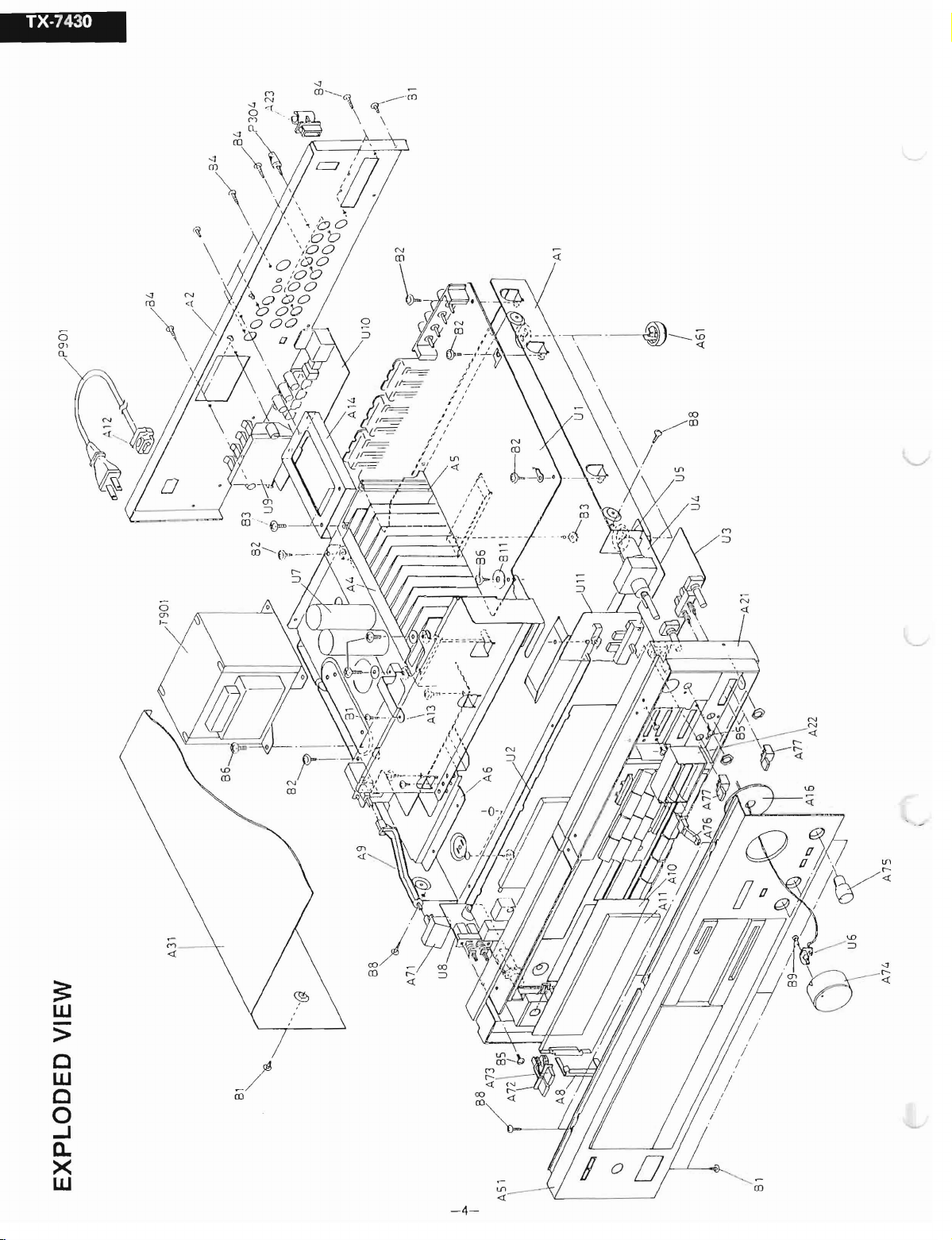
Exploded view _. . . . . . . . . . . . . . 4
Parts list . . . . . . . . . . . . . . . . . . . . . . . . . . . . . . . . 5
Circuit descriptions 6
Block diagram - Amp. section
- Tuner section Block diagram
Packing view
Adjustment procedures __ .
Pc bca rd view/parts list
Power amp. . . . . . . . . . . . . . . . . . . . . . . . . .
FM
/AM tun er 25
Display . . . . . . . . . . . . . . . . . . . . . . . . . . . . . . 29
Preamp. . _. . . . . . . . . 30
Remot e cuntrol . . . . . . . . . . . . . . . . . . . . . . . . 31
Switch
Spea ke r 32
Volume 32
Schematic diagram
Amp. section " 23
Tuner section 27
Disassembling prccedu res 33
of
IC 14
..
. . . . . . . . . . . . . . . . . . . . . . . .
- . . . . . . . . . . . . . . . 12
.,
. . . . . . . . . .
..
..
..
..
13
17
18
21
3 1
ON
AUDIO
KYO
COMPONfNTS
®
- 1-
SPECIFICATIONS
AMPLlr-IER
Power
Musi c ~1
Continuous
Total
ll arm o ni c Dis tor tio n:
IM
Distort
D~rllping
FroClu8
RIAA
Ouvia tio n:
Se
ns iti vit v
Pho
no
Signal-lo-Noisu
Tone
COIlIIOls:
MUl
ing:
Output
Power
Power
ioll
:
Factor:
11
CY
Responso:
aud
Ovet lo ad :
SECTION
:
Output
:
Outp
lmp
cd a n co :
Ratio:
45
channels
than
2
x
2 x 78
2 x 70
ut:
2 x 55
0.08% at rated
0.08% at 1
0
.08
0.08 % at 1
35 at 8
20 - 30
20 Phono
CD/Tape
Tape Rec:
120mV
Phono: 85dB
CD/Tape:
Bass: ±
Treble:
-20dB
watts
per
driven
0.08% TH D.
126
watts
watts
watts
watts
watt
% at
rate
watt
ohms
.000
20.000
:
Play:
150mV/3
RMS
channel,
. from
at 4
ohrns.
at 8 ohms,
at 4
ohms,
at 8
ohrns,
power
outpur
d
power
ouput
Hz ± 1
dB
Hz ± 0
.8dB
2.5mV/50
150mV/50
.5
at 'l kHz,
(at
10rnV
75dB
95dB
80dB
±10dBatl0kHz
min.
20Hz
1kHz
1kHz
1kHz
1kHz
kohms
0.08%
input
10dB
RMS.
to
20kHz.
(DIN)
(DIN)
(DIN)
(DIN)
kohms
kohms
(phono)
THD
, A
(IHF
A-202)
(A
weighted)
(IHF
at
100Hz
at 8 ohrns,
w ith no
weighted)
A-202)
both
more
TUNER
FM
Tuning
Usabio
50cJO
Captut e Ralio:
Imago Hei
Ir: Rojocli
Signal
Selecti vity
AM
ll arruo
Fro
St oreo Separ arion:
AM:
Tuning
Usable
Image Rejo
IF Rejeclion
Signal
Harm onie
GENERAL
Dimensions
SECTION
:
Rango :
Sunsiti
Ouio rinp
ectiou
oll
-lo
-Noiso Rati o:
Suppression
nic
DIslortion
quuncv
Rosp
Rango :
Sensitivitv:
clion
-Io-Noise
Otstoulou:
vitv:
Snnsitivitv
R~lio:
onso
Ralio
(W
Weight:
Ratio:
Ratio:
:
:
Hario:
:
Ratio :
x H x
87 .5 - 108
Mono
Stereo: 18
:
Mono:
Stereo:
1
.5dB
85dB
90dB
Mono
Stereo:
50dB
50dB
Mono
Stereo: 0.30%
30 45dB
30dB
522
30~V
<lOdB
40dB
40dB
0.7%
D):
.0MHz
:
:
DIN
(±300kHz. 40kHz
:
15.000Hz ± 1.5dB
at 1kHz
at
100
- 10
- 1611 kHz
435
x 11 0 x
17
-1/S"x <1
7.5 kg .. 16 .5 Ibs.
(50kHz
12.8dBf.
1
75
23~V(S/N
75
18
37.2dBf
72dB
66dB
0.15
.000Hz
(9kHz
-3/S
.0\lV
ohms
.0dBf.
ohms
.0dBt.
%
steps)
3<15
steps)
(S/N
.
m[n
"x
13-1/r
1.2~V.
26d
DIN
2
.2~V.
46dB.
DIN
2.2~V.
20~V.
dev.)
75
ohms
B.
40kH z Devi
75
ohms
40kHz
75
ohms
75
ohms
.)
Devi .)
Spec
llicatiorts arid Ieatures are
subject
to
chanqe
without
-2-
notice.
TX·7430
Remote
Tr
ansmiu
ign
S
Power
Dim ensrions (W x H x
Control
er:
nl range:
supply:
transmitter
0)
:
RC
-82S
Inlrar
ed
Appr
o x. 5
Two
"AA"
64 x 18 x
meters
baueries
149
2-1/2" x 11/16" x 5-7/8
110
Weight
:
grams 3.9 oz.
SERVICE PROCEDURES
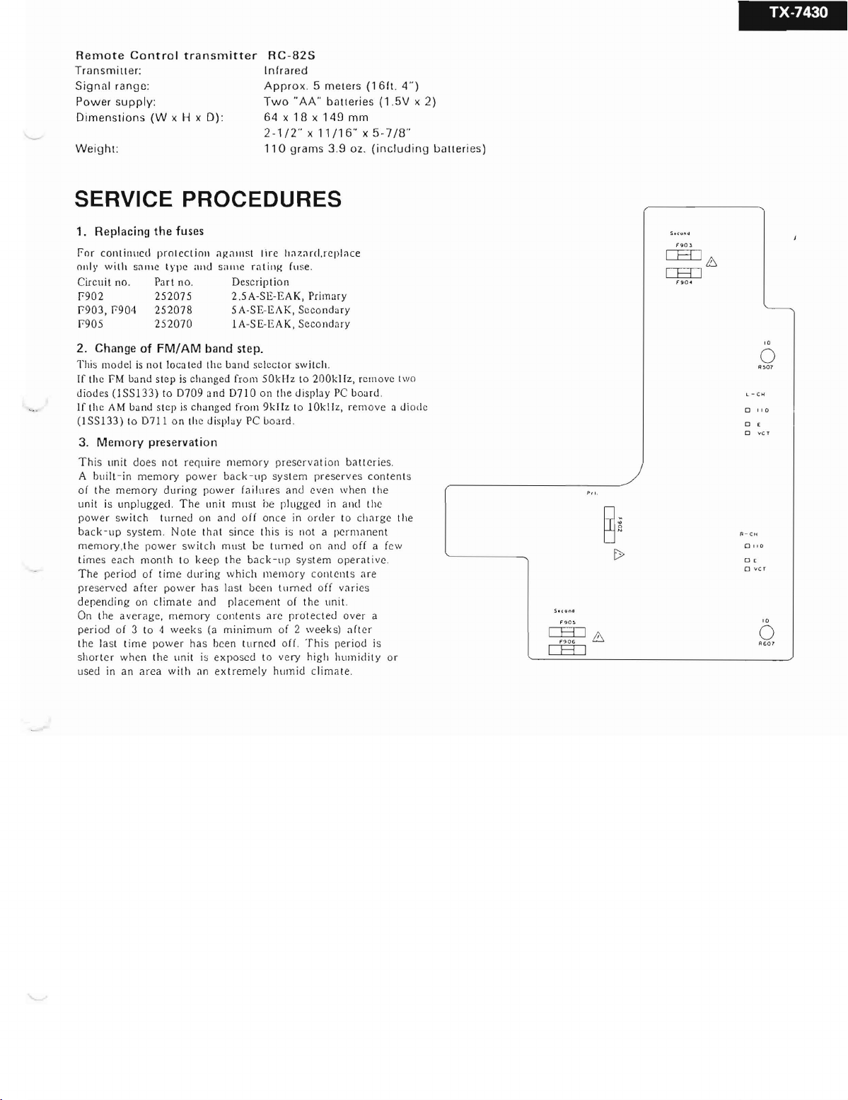
1. R
eplacing
f or co nt
0111\' w ith saure tvp e
Circu it no.
f9
02
f903
, P9 04
P905
2 .
Change
This mo de l is not loca red Ihe band sclcc to r sw ilch.
If th e PM b
died es
If th e AM
(lS
S133)
3.
Memory
Th
is un it
A hu ilt-in me
01 th e m
unit
is unplugged. The unit
power sw itch t
ba ck
-up
mem ory ,the pow
times
each mont
The per
prese rved
d
cpen
din g on
On the
peri od of 3 10 4
the last tim e pow
shor l
er
used
in an a rca
the
fuses
inucd
prrn
cc tion ;);:;Ullst lir c ha za rd.re plnce
and
s.uuc
rat
ing (use.
Part
no. Des
25207
5
252078
252070
of
FM/AM
and
(lSS133)to07
step is eha nged from
band
stcp is chungcd from
10
0711
preservati
does 1I0t req uir e m
mory power
emory
system. No te rhnt since t h is is not a
iod of ti me
after
climate and
average,
whe n
the
band
09 and
on
the displuy PC board.
on
durin
g p
urn
ed Oll and
er
switch rnust be
h 10
keep
dur
ing
pow
er
has
mem ory conten ts are p ro tec ted
wee
ks (a mi
er
ha s been
un it is ex
with
an ex tremely
cripti
2.5A-SE
5A-SE-EAK,
lA-SE-EAK
step.
50k
0710
on the display PC boar d.
9kH
emor
y pr
bac
k- up sy stem prese
ower lailur
rnust
he pl
oll
on ce in o rde r to
the ba ck
whic
h mem ory co
la st
been
placement
nimu
m of 2
turncd
pos
cd to ve ry high
on
-EAK, Pri
Hz 10 200k Hz, rcm ovc rwo
z to 1
eserva
es
and
turn
-u
p systern o pe ra
turned off va r ies
of th e
off. T his pe
humid
mary
Sec
ondary
, Scc
ondary
0kHz,
tion baucries .
eve
ugge
d in
ed
00
nte
unit.
wee
clima te.
rves
n when t he
and
perma
and o ff a few
nts ar e
over
ks) af ter
hum
mm
rernov
char
riod
idit y o r
(1
6ft.
(l
.5V x 2 )
(in
clutl
e
01
co n ten ts
the
ge th e
nent
tive
.
a
is
4")
"
ing
diodc
uaueri
es)
o I I 0
o ,
o
Pli
.
0 11 0
0'
o vc r
TX·1430
o
0 '
Q
;:
W
-
>
C
W
C
o
--I
a.
><
w
-4-

PARTS LIST
REF.NO
Al
A2
A3
A4
A5
A6
A8
A9
A
I0
A l l
A12
A13
AI4 27 14 1123A
A15
A2 1 27
A22
A23 27
A3 1 28 18
A51 l AOO1121
A52
A61 27 175 13 0
A71 2832
A72 28
A73
A74 28
A75
A76
A77
BI 834
B2
B3 838 4
B4
B5
B6
B7
88
B9
BIO
.
PART NO.
27100
121 A
27
1209
43 A
27 130470
27 13046 8A
27
16020
1
27130
469
27
190
359
27273030C
28 133
176A
2
8130242A
27
300750
27141122
272702
16
110338
27110339
27
190525
27
190526
190
105
4356A
28
184357A
lA
OI0 12 1
28140
220
2796
283 227 95 A
322469
28322304 -1
28322
470
2832230
283
28322928
28322929
2832292
28322925
28322926A
28322927
83 1
834
82 1
8304
82 1
833430080
8800
830
322
92 2B
22923B
430068
1300
4008
4301
4300
40089
4200
11
440109
5-1
4
88
08
6
4
A
A
8
8
A
9
DESCRIPTION
Chassis
Back p anel
Bracket , shie lded
Bracket , rad iat or
Radiat or
Bracke
t, power tr ansforrner
Holder, dial plat e
Join t L
Back
platc
Dial plate
~
Strainrclicf
Bracket
F
Brack et R
Spacer
Fro nt bracket ass 'y < S>
Front br acket ass'y < B>
H
older,
slide r < S>
Hold er, slider < B>
H
old
er, ante nna
Top cove r <
Top cover < B>
Fr
ont
Fro nt panel ass'y < B>
pane
S>
l ass'y <
S>
Cushion
Leg
Knob,
Power < S>
Kno b, Power < B>
Knob,
Speaker A <
Knob
, Speakcr A <8'>
Kriob , Spcaker B <5>
Knoh, Speaker II
Knob, Volun••
Knob. Volume < B>
Knob, Ton e < S>
Kno b, T on e < B>
Knob, Slide <5>
Knob, Slide < B>
Knob , Push <S>
Knob , Push < B>
3T rS+6 B(BC),
3Tn \'+8f\, Tapping scrcw
4TTB"'SC(BC), Tap ping screw
31TS+I0B
3P+6 FN(B C) , Pan hcad screw
4TTC+8C(B C) ,
2P+4F(B C) , Pan
3TTP+
8P(BC),
Rivet
4TT
C+I 0C(BC),
5>
<B>
$'
Tappi
ng scrcw
(B(' ), Tapplug screw
Tapp
ing screw
hcad
Tapping
Tapping screw
screw
screw
PART
REF .NO.
Bll
F90 2
F90 3, 1"904
1"
905,
F906
P304
P901
Q508
, Q608
Q509,
Q609
Q902, Q905
T901
UI
NO.
870060
252074
252078
252070
250600
44
253 128B or
2531
30A
220 178 3,
2201 784 or
2
201786
220
1773,
220
1774 or
220
1776
2201 754,
220
1755
22014040
220
2300
I A0085 69 ·2A
,
r
1405
199
U2 I A00 8570·2A
IA
0085
71·
U3
U4
U5 1A01 3573-1
U6
U7
UR I A01 3576·1A
U9 I AO
UI0
Ull
NOTE :
I AO
l
A013574
lA0
I A008578·2
1A00 85 79-2
<B>:
Only Black mo del
<
S>:
Only Silver mo de l
2A
I3572
·1
·1
08575-2A
I3577
·1 A
DESCRIPTION
Flat washer
~
2A-SE- EAK, Fuse, prirnary
~
5A-SE-EAK , Fuse, secondary
~
1A-SE-EAK, Fuse , secon
Termin
al GND
~
AS-CEE, Power
2SC3854(0),
2SC3854(Y)
2SC3854(P)
2SAI490(0),
2SA
I490(Y
2S AI4
90(
2SD I9 13( R) ,
2SDI9
13(S),
2SDI
406(Y)
2S DI
406(G
.6.
NPT-955G, Power tran sform er
NAAR-2869-2 A, FM/AM
pc b
oard
NADlS-2870-2A
b
oard
ass'y
NAAF-2871-2A,
board
ass'y
NAAF-2872-1, Volum
ass'y
NAETC-2873-1 , V
pc board ass'y
NAD IS-287 4-1, Vol
pc
boa
rd ass' y
NAPS-2
and
power supp
NASW-2876-1A,
pc
boar
d ass'y
NAETC-2877 -1A,
pc bo ar d ass' y
NA
ETC-2878-2,
terminal pc
NAAF-2879-2,
or
) or
P)
R)
ass'y
875
-2A, Power
board
supply
or
, Display pc
Prearnplif'ier pc
olum
ume indicato
ly pc
boar
Speake
Speaker
Remote co ntro l
ass' y
Switch
ass'y
NO TE: THE
CO MPON
CR IT ICA L F
S
HOCK. REPLACE
SPECIFIED .
dary
cor d
tune
r
e pc boa rd
e rno to r
amplifi
er
d ass'y
r switc h
term ina l
pc
boa
rd
OR
r
ENTS
IDENTIF
RI SK O F FI R E AN D
ON LY W IT H P
IE D BY
MARK~
ELE
ART
AR
CTI C
NU MBE RS
E
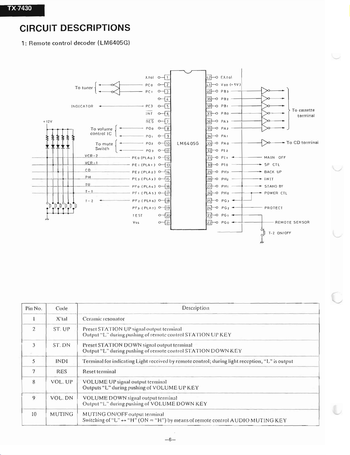
CIRCUIT DESCRIPTIONS
1:
Remote
control
decoder
(LM6405G)
• 12V
Ta
INDIC fl TOR
r
---.-L!J
tun nr {
Ta v
ca n
VCR - 2
VCR - ,
c.p
P H
T- I
T - 2
Ta
Sw
~
alu
tra
itc
f----
me [
l lC
mut
e [
h
..
x.i o t
PCo
pc
,
PC]
IN
T
~ E S
PO o
po,
p o>
p o ,
PEo
(PLA
O )
I (P
LA'
PE
PE > (P LA 2 )
P E , ( PL fI , )
P F> ( PL fI
Ph (PLfl7)
TEST
Vss
o---E
)
.)
LM 64
05G
E X
V
oo(
PB'
PB
PB I
P Oo
P
A'
PA>
PA '
PAO
P
I2
Pl
PI O
PH,
PH,
PHI
PG ,
PG2
P
G,
PG o
.la
2 -
I
l
'5V)
- - f-- -
-I
,----- -
--I
'------j
-
~---
f---
-
~---
-~
---
-
-t-
- - - ..
-
-t---r-
..
-+-- - -
-
~---
- - -
-PHo
-I
;>0
-j
)
0--
-j
;,.0---
M
..
SP CTL
..
BACK UP
I N I T
STAND
POWER CTL
PROTEC
-+---
t
- - -
- -
Ta casset te
- Ta CD t erm inal
AIN
OFF
BV
T
RE MOTE S
T- 2 ON IOFF
t
erminal
ENSOR
!'ill No . Code
-- - - - - -
I
2
3 5
5
7
8
9
10
X't al Ccr.unic rcso ua to r
ST.
ur
1'.
D N
(NDI
RE
VO L.
VOL.
MUTIN
S
U!'
DN
--
G
----
Pr
oset
STATION
"L"durin
O ut put
l'r
esct S
TATION DOWN
Output"L"
T
erminal
Re
V
OLUME
Outputs
V
OLUM
OUlpUI " LU
MUTI
Switching of
Ior
set
termin
"L"
E D OWN signal ou tp ur t
NG O N/OFF
---
U!'
sigIlai o u tp ut
g pu
shin
g of rc mo tc co n tro l ST AT ION LiI'
sig na l
durin
g pu
shillg
o f rc
indic ntiug Ligh t recci v
al
U!'
signa l o u tpur tc
during
push
ing o f
durin
g pu
shing
o f
VOI.UMEDOWN
o Ul
pull
erlllinal
" L"
++"
H"
(ON
= "
ter
min
outpur termin
mote
co u tro l ST ATIO
ed
by rcmotccout
rmiu
al
VOLLiME
erm
inal
H")
by nieans o f
-6-
Descrlpti on
al
al
ur
KEY
KE Y
renr
KEY
N D O WN K
rol ;
during
ote
co n tro l A
EY
liglu
rec
cption,"L" is
UDI
O M
UTIN
G K
output
EY
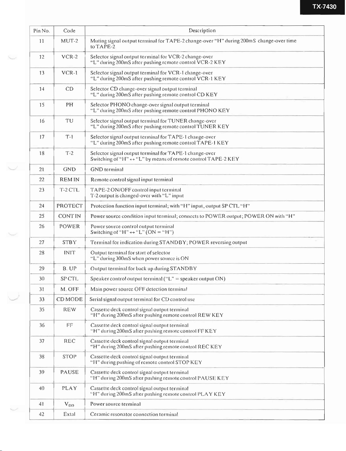
TX-7430
Pin
No .
11
12
13
14
15
16
17
18
21 G ND
22
23 T -
Code
MUT-2
VCR-2
V
CR
C D
PH
T U
1'
-1
1'-2
REMIN
2CTL
-1
Muting
loTAPE-2
Selector
"L"
during
Select
or
during
" L"
Select
or
"
L"
during
Select
or
"L"
during
Selector
"L"
during
Selcctor
during
" L"
Select
or
Swit
ching of
GND
terminal
R
cmote
TAPE-
20N/OFF
1'-2
outpur
signal
out
put
signa l output te
200mS
aftcr
signal ou tput
200mS
afr
CD
changc-over
200 mS aft
PHONO
sign al outpu t t
signa l outpu t t
signal ou tpu l
change-over
200mS
after pushing
200mS
aftcr pushing
200mS
after pushing remote
" J-I"+-> " L" by
control
is
signa l
chang
control
ed-ov
terminal
terminal
er pushing remote
cr
terminal
for T A
rminul for
pu
shing
signa l
pu
shing remote control
erminal
erminal
input
input
cr
VCR-
rcmote
for
VCR
outpur
sign al
remote
for
TUNER
renr
ote
forTA PE
for TAI'E-1 cha nge-ovc r
mcans
o f rem ote co ntro!
terminal
terminal
wiih "L"
input
Descrlprion
PE-2
cha nge-o ve r ''\-'1''
2 cha nge-ove r
contr
ol
VCR-2
-I change- ov cr
control
VCR
terminal
out
C D
put
terminal
co utrol
PHONO
cha nge -o vc r
control
TUN
-I change- o vc r
cont
rol
TAPE-I
during
KEY
-1
KEY
KEY
KEY
ER
KEY
KEY
TA PE-2 KE Y
200mS
chang
e-over
tim e
24
25 CO
26
27
28
29
30 SP
31 M .
33
35
36
37
38
39
PRO
POWER
STBY
C D
PAUSE
TECr
NT
INIT
UP
B .
CTL
OFF
MO
REW
Fr
REC
STOI'
Pror
Power
IN
Power
Switching
T
Output terminal
" L" c1ur
O utpu t
Speaker control
Main pow
D E
S
Cassette deck
"H"
-
C
" H"
Casse tte d e ck c
" H"
Cassc tte
"H"
Ca
"/-I"
eeti on
so urce
so urce
erminal for
ing
terminal for
erial
signal
during
asse
ue deck
tluring
durin
deck contr
ehrring pu
ssett
e d
timing 200mS
function
of
300mS
er
outpur termin
200m
200mS
g 200mS afte r pu
eck
condiiion
control
"H"
+->
incli
cati
for
out pur
sour
cc
controi
S aft
control
ontrol
shing
control
input
input
outpur
"L"
on
during
stnrt
wh cn pow
back
terminal ("L
OFF
signal
er pushing
signa l outpu l te rmina l
after
pu
signnl o utpur
ol
signal
of
rcin
signal o utpur t
after pushing
terminal;
(ON = "H
of selector
up
det
al f
shing
shing rem
or c co ntro l ST O P K
with
"
terminal ; conn
terminal
")
STANDI3Y; POWER
er
so urcc is
during STANDI3Y
cction termina
or
CD
ou tpur t
rernor e
rern orc
o utput
rem
ON
" = spea ke r o utput O N)
co ntro l usc
erminal
conrr
cont
terminal
ore
cont
terrninnl
erminal
ote
cout
J-I
"
input , out
ccts to
I
ol
rol
rol
rol
REW
rr
REC
EY
PAUS
put
POWER
rever
KEY
K
EY
KEY
E K
SI'
CTL
" H"
output ; POWER
sing
outp u r
EY
ON
with " H"
--
40
41
42
PLAY
Von
Extal
Cass
ette c1eck
1-1 " during 200m
"
P
ower
so
urce
Ccr
ami
c re
sonator connccti
contr
ol signal ou tpur t
S a fter pu sh ing renr ot e
terminal
on
terminal
ermin
al
cont roll'LA Y KEY
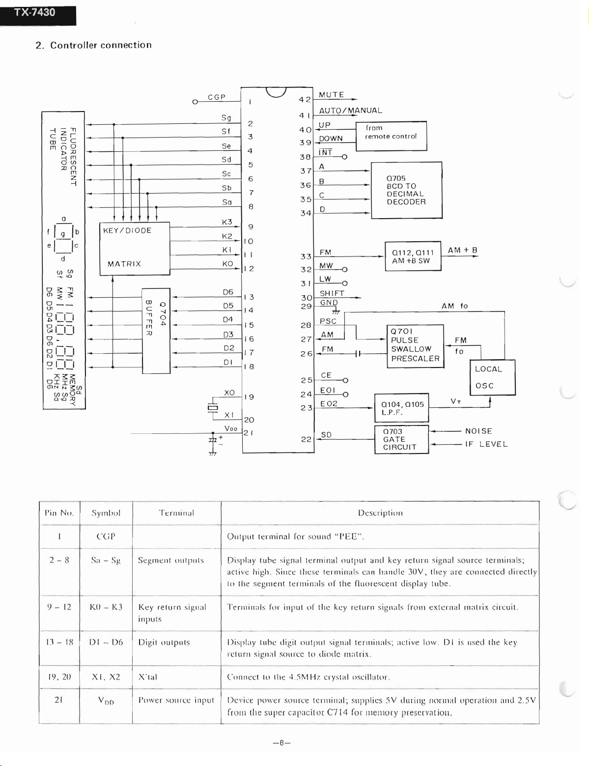
TX-7430
2.
Controller
connectio n
-;
--"
z r
c
~ c
rn
()O
rn
!>JJ
-:i m
O (J)
JJ()
rn
z
-;
0
f
I g ib
el
le
--
d
(J) _ (J)
<0
0
;:: -"
(J)
::E3:
0
__
(Jl
~ CD
GlI-I-1
o ~ -
(J)
0 1- 1- 1
N - -
~ CD
;>;
;:: ;::
OII
m
O)N
N
~(f)
(J) (J) o c>-
0<0
JJ
-<
-.
KE
Y/O
MATRIX
/OOE
-
rn
L......-
C
-q
-"
m
.o
l
MUT E
4 2
AUTO/MA NUAL
4 1
UP
4 0
DO
30
29
27
25
22
WN
INT
A
B
C
0
FM
MW
LW
SHIFT
~
P S C I
AM I
FM
.
CE
EOI
E
02
SO
3 9
38
37
36
35
34
3 3
32
3 1
28
2 6
24
2 3
Irorn
re
mot
e con trol
070
5
BCD TO
DECIMAL
ECODE
D
~
R
0 1
12
, 0 1 11
AM +B SW
AM + B
AM
10
Q7 01
PULSE FM
1
1--
SWALLOW
PRESCALER
10
I
LOCAL
~
~
I
01
0 4,
0105
L.P. F.
07
I
GATE
CIRCUIT
I
0 3
I
.
VT
NOIS E
IF L EVE L
OSC
t
2
3
4
5
6
8
9
10
I I
12
13
14
/5
/6
17
18
19
20
2 1
\J
I
7
CGP
\..T
Sg
SI
Se
Sd
Se
Sb
So
K3
K2
KI
KO
-
0
--J
0
.l>
-
-
06
05
04
03
02
0 1
XO
5
X I
T
Voo
!
~
I' in No .
I
2 - 8 S;l - SI'
lJ - 12 -KO - K J
D-
IlJ, 20
2 1
I S
Sym bo l
(
'(J
-
IJI
X 2
X I .
V
DO
P
1)6
Te
Segme nt
retu rn sig ll<!l
K ey
in pui s
ou
D igit
X 'l al
Po w
er
rmi
nal
O u tp ut t
- - -
- - - -
Oll
I put s
tpu
ls D isplay tu bc digil
sot I rce
inpu
Displ
ay t ube
ac ti vc hi gh. Sincc Ih esc
to th e seg
Te
rmiuat
rc tur n signal so urcc
Conu
ec t
Dev
t
ice
[ro ru the super capaci tor C7 14 Ior memo ry preservat ion.
..
erm
inal
Io r sound
te
s i g n ~
meut
s ro r in p ut o f t hc
10 t he 4
pow c r so 1I rce
rmina
1
terminuls
out pul signal
to di odc
.5M
H z
tc rmi nal ; sli ppl ie5
- 8-
Dcscri
'
'I'E
E'' .
l ou tp u r
ermi
nal-, can h,lIl d le JO
t
of
ih e tl u
or
ret u rn sigllals
key
te n u iua is:
matri
x.
cry
sral osci l
p tion
rc
ruru
an d kc y
escen t di spla y
nc ti ve lo w. 0 1 is uscd th e key
lutor.
5V
dnr
signa l source te
V,
th e y are co nncc rcd d
tub
e.
lr
om extc ru al
il lg no rma l operanon and
maui
rmi
nals:
x circuit.
irec
2.5 V
t ly
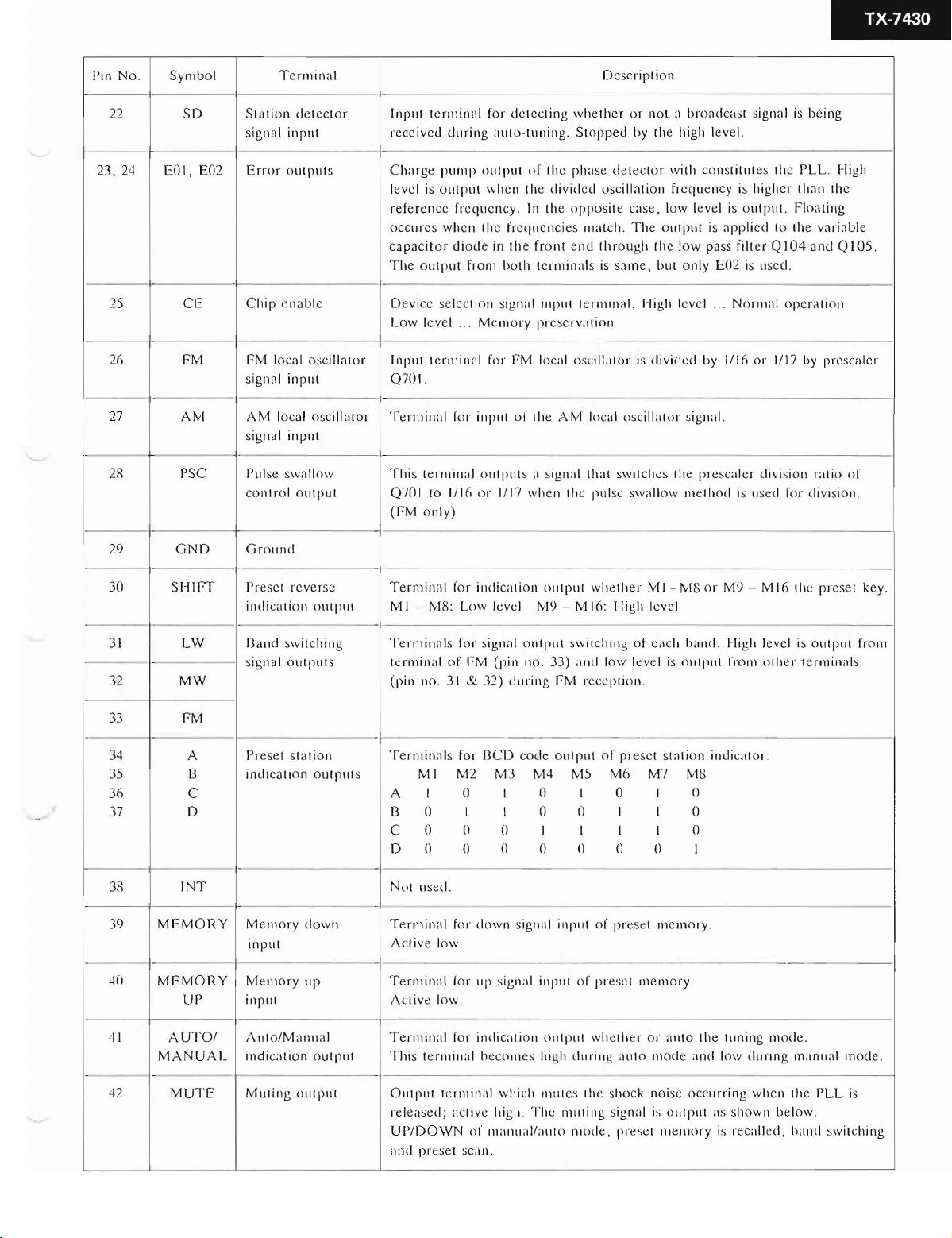
TX-7430
Pin No .
22
Symb
SO
ol
Te rmina l
Sta tion det e
signal input
Err
2:\, 24 EOI, E02
25 CE Chip
26
27
FM FM local ose illato r
AM
or o u rp u rs
enab
slgnal
input
A M loeal osc illa ro r
signa l
inp
2R PSC Pu lse swallow
com ro l ou tpu t
etor
Input termi nal for de tee ting
reeeiv ed d uri ng uu
Char
ge pum p ou tp ur of thc phas e detecror with
level is o utpu t whc n
io-
tu ning.
t he dividcd oscillation frcqu c ucy is highcr rhan
refc ren cc frcqu cn cy. In th e op pos iie case , low le vel is output. Floa ting
occ urcs whcn thc frcq ucucies match . T he o
tor
ca paci
T he
diode in rhe fro nt
ou lpu t fro m bot h tcrm iuals is sa me , but o nly E0 2 is usc tl.
le Deviee selcction signal inp ut t
l. ow le vel ... Mem ory pre sc rv.u ion
Input termin al
[or FM loeal osc ill.uor
Q7()1.
Termin
ut
al
for inp ut o f ihe
Thi s t
ermin
al
outpu
Q70 1
to 1/10 o r 1/17 whe n rhc pu lse swa llow meihod is used [or d ivision.
A M local oscill.uor signal.
ts a signal t luu swirchcs t he pre sc.iler division r.uio of
(FM only)
Dc scripiion
whethcr
Stopped
or not a brondcast signal is bcing
by t he high level.
utp
end
thr
ou gh rhc low pass filler Q
ermin
al .
High lcvcl
is divided by I/l o o r
--- ---
cons
i i ru res th e PL L. High
ih
c
ur is npp licd 10 the varia ble
I04
a nd Q
I05
... No rma l op era no n
1/17 by prcscalcr
.
29
30 S
31
32
33
34
35
30
37
3R INT
39
,.j()
4 \
-
42
G NO
HIFT
LW
MW
r-M
A
B
C
0
MEMO
ME M
RY Merno ry down
OR
UP
AUTO
I
MANUAL
MUTE
Grou
nd
Pre set rcve rsc
indieatio n ou tp ur
Ba nd switching
signal o urputs
Prese t sra rion
indica rion OUlpU
inpu t
Mem ory up
Y
inpu
t
A u
to/Ma
indi
cation
Mur ing o ut
nu al
outp
pu l
Te rmina l fo r ind ienn on ou tp ul whei her
MI - M8: Low lcvcl M9 - M 10: High
Terminal
terminal of FM (pi n
(pin no . 3 1
Te
IS
A
n
C
0
Not
Terminal
s for signal o utpul switehing of cach band . High level is outp ul frorn
11
0.
& 32) duriug r M rece prio n
rmi na ls for
MI M2
I
()
() ()
() ()
uscd.
ßCO
code o utpur of pre sc t stutio n indic.
M3 M4 M5 MIl M7 MS
()
I
I
I
()
()
for
down signal
Acriv e low.
T
ermin
al for
up signa l inpu t
Ac iive low.
-
Te
rmina l Ior irul ica tion
T his t
erm
ur
O utput t
inal becom es hig h dm ing ,1
ermin
al which
released; nctivc high . T in: muti ug signal is outpur as show n below .
UP/OOWN
ancl
preset
of manu ul/au to moc le , presel Illelllory is reeall ed , b.uid swirching
scan.
---
MI - MS o r
-
M9 - MI Il the prese t key.
level
33) .md low lcve l is out put lro rn o rher t e rm inals
..
-
-
uor.
()
I 0 I
()
0 I I 0
I I I
I
() ()
()
inp ut o f p re set
()
mc m
()
()
I
ory.
of pre sc t mem ory.
output
mute
whe t her or auto i he tuni ng mod e.
11
10 morle a nd low (hlring munu nl mo de ,
s rhe shoc k noisc oeeurrin g whcn rhe PLL is
TX·7
430
Control key and diode matrix connections
K3('1) K2(
' -
Sg(2)
Sr(3)
S
e(4)
S
d(5)
Sc(6)
Sb(
7) HI -l l L
Sa( H)
--
M4 /M 14 M3 /
MH
/MI
H
S I-
f1n
A U
TO
MAN
UAL
l'NIJ
'l0/'ik
Hz ' LW2 ' L W I
[) I (I H) ' I3A N I) 0
Dio
de
111"1
z .
rix
DANDI
.. ..
....
•
n A N DII,
lO
/lIkH
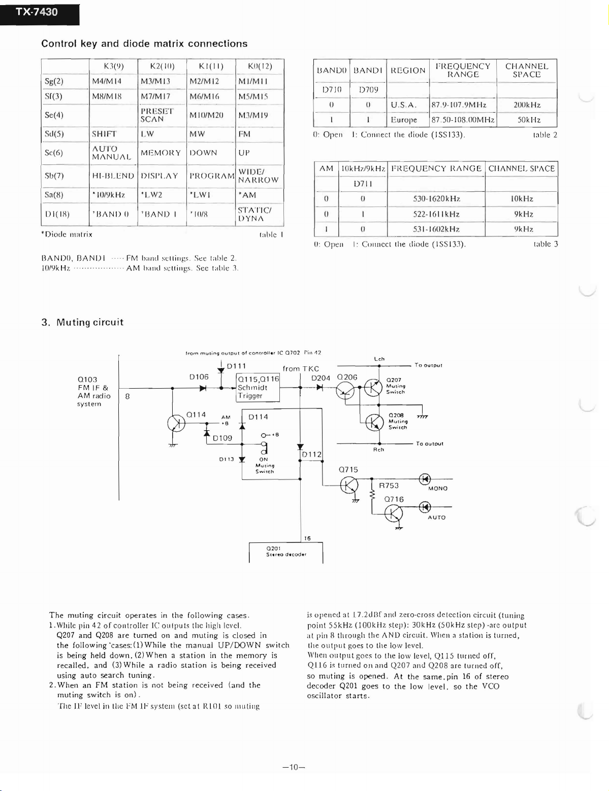
3. Muting circuit
01 03
FM IF &
AM rad io
svstam
111)
MIJ
7/M17
M
-
I'IU
,SET
SC
A N
_ .
LW M W
M
EM
I) IS I'
OI ~ Y
I.A
Y
M2/M 12 MI
MU
MIIJIM20
---
I)
OWN
I'R O GI ~ A
--
' I
' IJA N D I
"M
I" I/\(I oc llillgs . Se e tnble 2 .
AM
I
,,"
\(I oe ll illgs . See tub le 3.
8
11tH
lro m
0 106
KI
M I(,
mUl
(II)
--
-
in9 Ou
..
M
- -
- -
IPU!
5/M1
M
----
M3/M
_-
" M
UI'
W I
N A R
---
'A
-----
ST
DY
0 ' c o o
,-
- -
KII( 12)
/MII
5
IY
-.
DEI
IW
M
AT
IC/
N A
rnblc I
trou
--
-,
W
-
er rc
070
from
llA
N DIl BA N D I
-- - _ .
D7 J0
0: Open I : Conue ct
A M
lJ
0
--
I
11
: O pen I: Councct the diode ( 1
2 ri1\ '12
TKC
020
4
1)70 '1
0
0
1 I Europe 87 .50-
IOkH ,J9
kH
z
D711
0
1
11
Lch
FI~E
I
~E GI O N
U S .A . R7.'1- 107.'1M Hz 200k H,.
the
diocle (I S
FI~ E Q
UE N C Y I
530- 1620 kH z 10kH z
522
53 1- I
.-
QUEN C Y
AN
G E S
H
-
I08
.00 M H z
SI3
3) . tnhle 2
~A N GE
- 16 1l k
Hz
W2k
Hz
.'1.'1
133).
C I IA NN E L
I'A
CE
50k
Hz.
CII ANN EL SI'AC E
9k
Hz
'1k Hz
iable 3
The rnuting
1.Wb ile pi1l 4 2 of co ut roll er IC ou t pu ls thc high lcvc l.
Q207
the foll ow ing "cascs
is
recalled. and
using
2.
When
muti
Thc IF levcl in th c I:M
cir
cuit
ope rat es in the fo llo
and
being
held
aut
o search
Q208 ar e
down.
(3)
Whil
tumed
.f
Ü
While
(2)When
e a
tuning
on and
radi
.
an FM st a tion is not being rec
ng s
witch
is on) .
110
systcru (
wing
case s ,
muting
is
clo
the ma nu al UP/DOWN
a st at ion in th e m
o sta t ion is be ing rec e ived
eive
d (a nd
sct
a t
IUOI
SO
llllll
sed in
emory
the
ili g
0 20 1
S
tereo
swi t ch
is
011 2
0 7 15
16
dec
oder
is 0 I'C llC U a t 17 .Zd Br
po int 55 k Hz
a
t p iu R th rough the A ND circuit. Wheu a sla t ion is tur ued ,
tlie o
utp
ut goe s to lhe 10
"'h
en o utput gocs 10 t he 1
Q I 16 is tu rn ed
so
rnut
ing is
decod er Q201 g
osc illa tor st
Reh
R7 5 3
and
(100kHz
art
step) :
Oll
and
Q207
operred.
At
oes
to th e low level . so
s ,
zer o -c
30kHz.
11'
levcl .
011'
level,
nn d Q2 08are
the
M
ONO
ross
d ct c
ctiouc
(5 0 kHz. st cp ) -ar c o utp ut
Q1l
5 t ur ncd of'I,
sarne
, pin 16 of
tunr
the
irc
uit
ed o ff,
ster
VCO
(Iuning
eo
-1
0-
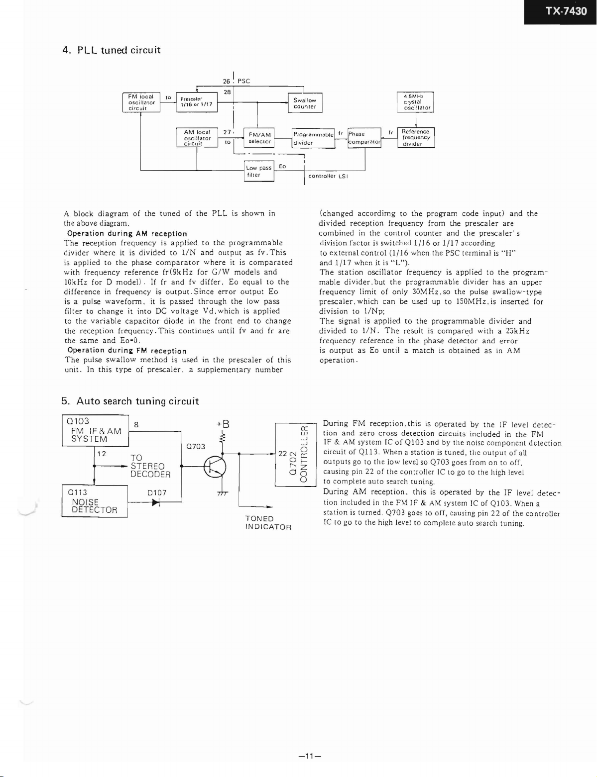
4.
PLL
tuned
A
block
the
Operation
The
div ider
is applied
with
10kHz
difference
is a
filter
to
the
the
Operation
The
unit
diagram
above
diagram.
reception
wnere
to
frequency reference
for
in Ireq uency is
pulse
waveforrn
t o
change
the
variable
reception
sarne
and
pulse
. In th is t
circuit
of
the
tuned
during
AM
phase
. it is
it
into
capacitor
.
w
metho
of
pre
reception
c
ornpar
oe
y .
This continues
reception
scaler
frequency
it is divi ded to lIN
the
D rnodel l . If fr
frequenc
Eo·O
du r in g FM
s
wallo
ype
of
the
is
applied
fr (9k H z for G
and
output.Since
passed t hr
volt
diode
d is
aror
fv di
age
in
used
to
and
where it is
Vd ,
the
in
. a supplernent
PLL
the
ffer
ough
front
the
26 I
outpur
/W
. Eo
err
which
unt
r-
sc
is
shown
in
pro gr
arnmable
as fv .
This
cornparated
model
s a nd
equal
to
or outpur Eo
the
low
pass
is
applied
en d to
and
scaler
ary
change
fr
of
number
il fv
pr e
the
are
thi
TX·7430
(chan
ged
acc
ordirng
divided
combined
divi si
to
and 1
The stat
m
frequency limit
pr
divi
The
divided
frequ
s
is
operation
recept ion
in
the contro! counter
on
Iac
ex
able
escaler i which
outpur
ror is s
tern
al con tro l
/17
when it is " L ").
ion osc illat or
div
ider .but
sion
to
1/Np;
sign a l is
t o l
/N
ency re fere nce in
as Eo
.
to
frequency
wit
ch ed
(I/!6
the prograrnm
of
only
can
be
applied
. T he
until
the
program
from
1/16
or
whe n th e PSC t
frequenc
to
result
a
30MHz.
used
the progr
the
phase
rnatch
y is
up to
is compared
is obta ined as in AM
the
an d
1/!7
app
abl
e d
so
the
ISOMHz.is
ammab
derector
code
input)
presca
ler
the
presca
acco rding
ermin
al is "H "
lied
to
ivider
pulse
le
divider
with a
and
and
the
are
ler' s
the
program
has
an
upper
swallow-type
insert
ed for
and
25kHz
e
rro
r
-
5.
Auto
Q103
FM
IF&AM
SY
STEM
Q113
N
OI
SE
DETECTOR
search
12
tuning
8
TO
STEREO
DE
CODER
D10 7
1""1
circuit
07
03
P
+B
2
TONED
INDICATOR
2N
OCC
r-- f--
06
During
FM
ti on a nd
IF & AM systern IC o f Q
circuit of Q113 .
0
cc
w
-.J
-.J
ou t pu ts go t o th e l
caus ing p in
u
(0
co mp lete 3U to sea rch t
During
AM
tion
included
station
is
JC
to go to th e high level to co mplete aut o search tu ni ng.
recept
zero cr
tumed
ion .this
oss
Whe n a sta tion is tuned , the o utp u r o f a ll
ow
22
of
the
recepti
in th e FM
. Q
703
is opera ted b y
detecti
on ci rc u its incl ud ed in
I03
and by th e
level so Q
con
on.
703
tro lle r IC t o go to the high leve l
unin
g.
this
is
IF
& AM
go es to
off,
no
goes from o n to off,
operared
system
JC o f Q
causin
g pin 22 of th e co
the
IF
leve
the
I03.
IF
the
level
When
isc co mponent d
by
l
dere
FM
ete
a
ntr
c-
ct io n
derec-
oll er
-11-
 Loading...