

Page 1
✔
✔
✔
HTC-V10X_En.book Page 1 Wednesday, July 21, 2004 2:49 PM
Contents
Introduction ........................... 2
5.1ch Home Theater System
HTC-V10X
HTE-V10X
PR-155X (AV controller)
DV-S155X (DVD Player)
HTP-V10X
SWA-V10X (Subwoofer)
ST-V10X (Speakers)
Instruction Manual
Connections ........................ 19
Setting Up ............................ 30
Enjoying Sound................... 34
Listening to the Radio ........ 41
Setting the Time .................. 47
Using the Timer Functions
Advanced Setting................ 59
Troubleshooting .................. 66
.. 50
Thank you for purchasing an Onkyo 5.1ch Home
Theater System. Please read this manual thoroughly
before making connections and turning on the power.
Following the instructions in this manual will enable
you to obtain optimum performance and listening
enjoyment from your new 5.1ch Home Theater System.
Please retain this manual for future reference.
Miscellaneous .....................69
En
Page 2
HTC-V10X_En.book Page 2 Wednesday, July 21, 2004 2:49 PM
WARNING:
TO REDUCE THE RISK OF FIRE OR ELECTRIC
SHOCK, DO NOT EXPOSE THIS APPARATUS
TO RAIN OR MOISTURE.
CAUTION:
TO REDUCE THE RISK OF ELECTRIC SHOCK,
DO NOT REMOVE COVER (OR BACK). NO
USER-SERVICEABLE PARTS INSIDE. REFER
SERVICING TO QUALIFIED SERVICE
PERSONNEL.
Important Safety Instructions
1. Read these instructions.
2. Keep these instructions.
3. Heed all warnings.
4. Follow all instructions.
5. Do not use this apparatus near water.
6. Clean only with dry cloth.
7. Do not block any ventilation openings. Install in
accordance with the manufacturer’s instructions.
8. Do not install near any heat sources such as radiators, heat registers, stoves, or other apparatus
(including amplifiers) that produce heat.
9. Do not defeat the safety purpose of the polarized
or grounding-type plug. A polarized plug has two
blades with one wider than the other. A grounding
type plug has two blades and a third grounding
prong. The wide blade or the third prong are provided for your safety. If the provided plug does
not fit into your outlet, consult an electrician for
replacement of the obsolete outlet.
10. Protect the power cord from being walked on or
pinched particularly at plugs, convenience receptacles, and the point where they exit from the
apparatus.
11. Only use attachments/accessories specified by the
manufacturer.
12.
Use only with the cart, stand, tripod, bracket, or table specified
by the manufacturer, or sold
with the apparatus. When a cart
is used, use caution when moving the cart/apparatus combination to avoid injury from tipover.
13. Unplug this apparatus during lightning storms or
when unused for long periods of time.
14. Refer all servicing to qualified service personnel.
Servicing is required when the apparatus has been
damaged in any way, such as power-supply cord
or plug is damaged, liquid has been spilled or
objects have fallen into the apparatus, the apparatus has been exposed to rain or moisture, does not
operate normally, or has been dropped.
PORTABLE CART WARNING
S3125A
WARNING
RISK OF ELECTRIC SHOCK
DO NOT OPEN
The lightning flash with arrowhead symbol, within an
equilateral triangle, is intended to alert the user to the
presence of uninsulated “dangerous voltage” within
the product’s enclosure that may be of sufficient
magnitude to constitute a risk of electric shock to
persons.
The exclamation point within an equilateral triangle is
intended to alert the user to the presence of important
operating and maintenance (servicing) instructions in
the literature accompanying the appliance.
AVIS
RISQUE DE CHOC ELECTRIQUE
OUVRIR
NE PAS
15. Damage Requiring Service
Unplug the apparatus from the wall outlet and
refer servicing to qualified service personnel
under the following conditions:
A. When the power-supply cord or plug is dam-
aged,
B. If liquid has been spilled, or objects have
fallen into the apparatus,
C. If the apparatus has been exposed to rain or
water,
D. If the apparatus does not operate normally by
following the operating instructions. Adjust
only those controls that are covered by the
operating instructions as an improper adjustment of other controls may result in damage
and will often require extensive work by a
qualified technician to restore the apparatus to
its normal operation,
E. If the apparatus has been dropped or damaged
in any way, and
F. When the apparatus exhibits a distinct change
in performance this indicates a need for service.
16. Object and Liquid Entry
Never push objects of any kind into the apparatus
through openings as they may touch dangerous
voltage points or short-out parts that could result
in a fire or electric shock.
The apparatus shall not be exposed to dripping or
splashing and no objects filled with liquids, such
as vases shall be placed on the apparatus.
Don’t put candles or other burning objects on top
of this unit.
17. Batteries
Always consider the environmental issues and follow local regulations when disposing of batteries.
18. If you install the apparatus in a built-in installation, such as a bookcase or rack, ensure that there
is adequate ventilation.
Leave 20 cm (8") of free space at the top and sides
and 10 cm (4") at the rear. The rear edge of the
shelf or board above the apparatus shall be set 10
cm (4") away from the rear panel or wall, creating
a flue-like gap for warm air to escape.
2
Page 3
HTC-V10X_En.book Page 3 Wednesday, July 21, 2004 2:49 PM
Precautions
1. Recording Copyright —Unless it’s for per-
sonal use only, recording copyrighted material
is illegal without the permission of the copyright holder.
2. AC Fuse —The AC fuse inside the HTC-V10X
is not user-serviceable. If you cannot turn on
the HTC-V10X, contact your Onkyo dealer.
3. Care —Occasionally you should dust the
HTC-V10X all over with a soft cloth. For stubborn stains, use a soft cloth dampened with a
weak solution of mild detergent and water. Dry
the HTC-V10X immediately afterwards with a
clean cloth. Don’t use abrasive cloths, thinners,
alcohol, or other chemical solvents, because
they may damage the finish or remove the
panel lettering.
4. Power
WARNING
BEFORE PLUGGING IN THE UNIT FOR THE
FIRST TIME, READ THE FOLLOWING SECTION CAREFULLY.
AC outlet voltages vary from country to country. Make sure that the voltage in your area
meets the voltage requirements printed on the
HTC-V10X’s rear panel (e.g., AC 230 V, 50 Hz
or AC 120 V, 60 Hz).
Memory backup
The HTC-V10X uses a battery-less memory
backup system in order to retain radio presets and
other settings when it’s unplugged or in the case of
a power failure. Although no batteries are required,
the HTC-V10X must be plugged into an AC outlet
in order to charge the backup system.
Once it has been charged, the HTC-V10X will
retain the settings for several weeks, although this
depends on the environment and will be shorter in
humid climates.
However, the clock and timer settings are cancelled.
For British models
Replacement and mounting of an AC plug on the
power supply cord of this unit should be performed
only by qualified service personnel.
IMPORTANT
The wires in the mains lead are coloured in accordance with the following code:
Blue: Neutral
Brown: Live
As the colours of the wires in the mains lead of this
apparatus may not correspond with the coloured
markings identifying the terminals in your plug,
proceed as follows:
The wire which is coloured blue must be connected
to the terminal which is marked with the letter N or
coloured black.
The wire which is coloured brown must be connected to the terminal which is marked with the letter L or coloured red.
IMPORTANT
The plug is fitted with an appropriate fuse. If the
fuse needs to be replaced, the replacement fuse
must approved by ASTA or BSI to BS1362 and
have the same ampere rating as that indicated on
the plug. Check for the ASTA mark or the BSI
mark on the body of the fuse.
IF THE FITTED MOULDED PLUG IS UNSUITABLE FOR THE SOCKET OUTLET IN YOUR
HOME THEN THE FUSE SHOULD BE
REMOVED AND THE PLUG CUT OFF AND
DISPOSED OF SAFELY. THERE IS A DANGER
OF SEVERE ELECTRICAL SHOCK IF THE
CUT OFF PLUG IS INSERTED INTO ANY 13
AMPERE SOCKET.
If in any doubt, consult a qualified electrician.
For European Models
Declaration of Conformity
We,
ONKYO EUROPE
ELECTRONICS GmbH
LIEGNITZERSTRASSE 6,
82194 GROEBENZELL,
GERMANY
declare in own responsibility, that the ONKYO product
described in this instruction manual is in compliance with the
corresponding technical standards such as EN60065,
EN55013, EN55020 and EN61000-3-2, -3-3.
GROEBENZELL, GERMANY
ONKYO EUROPE ELECTRONICS GmbH
I. MORI
3
Page 4
HTC-V10X_En.book Page 4 Wednesday, July 21, 2004 2:49 PM
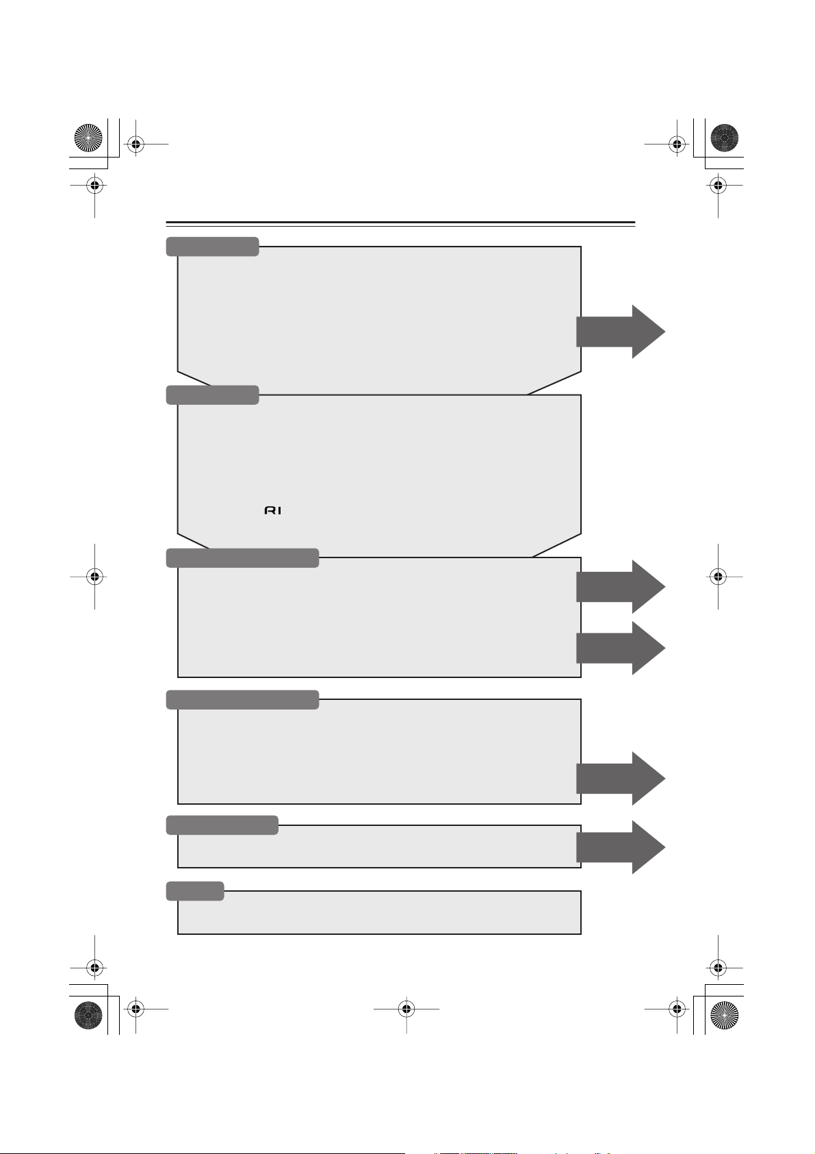
Table of Contents (Basic)
Introduction
Important Safety Instructions....................................................................... 2
Precautions ....................................................................................................3
Features.......................................................................................................... 6
Caring for the HTC-V10X............................................................................... 7
Supplied Accessories ................................................................................... 8
Preparing the Remote Controller ...............................................................11
Index to Parts and Controls........................................................................ 12
What is Home Theater? ...............................................................................18
Connections
Connecting the AV Controller (PR-155X) and the subwoofer (SWA-V10X) ......... 19
Connecting the subwoofer (SWA-V10X) and the speakers (ST-V10X) ................. 20
Connecting the AV controller (PR-155X) and the DVD player (DV-S155X) ......... 22
Connecting an MD recorder .................................................................................... 23
Connecting a CD recorder, tape deck, or VCR........................................................ 24
Listening to TV surround sound.............................................................................. 25
Connecting to other digital components.................................................................. 25
About System functions........................................................................................... 26
Connecting an cable ........................................................................................ 27
Connecting the supplied FM and AM indoor antennas (aerials)............................. 28
Advanced
Setting Up and Playing
Turning on the PR-155X .............................................................................. 30
Setup............................................................................................................. 31
First Time Setup (for European models) ................................................................. 31
Changing the input source setting ........................................................................... 32
Setting the multi channel audio output .................................................................... 33
Playing a Connected Source ......................................................................34
Muting the sound ..................................................................................................... 34
Listening through headphones................................................................................. 34
Listening to the Radio
Auto Preset Memory — Automatically storing the stations (only for FM)............. 41
Using RDS (European models only) ....................................................................... 42
Switching between Auto and Mono mode............................................................... 42
Preset Memory – Receiving and programming your favorite stations.................... 43
Setting ACCUCLOCK to Use a Specific Station .................................................... 45
Listening to a preset station ..................................................................................... 46
Erasing a preset station ............................................................................................ 46
Setting the Time
Setting the Time ...........................................................................................47
Displaying the Clock ................................................................................... 49
Others
Troubleshooting........................................................................................... 66
Specifications .............................................................................................. 69
Advanced
Advanced
Advanced
Advanced
4
Page 5
HTC-V10X_En.book Page 5 Wednesday, July 21, 2004 2:49 PM
Table of Contents (Advanced)
Operating the TV from Remote Controller .................................................64
Advanced Setting Up
Setting the Distance to the Speakers ........................................................62
Balancing the Speaker Volume Levels....................................................... 63
Enjoying the Surround Sound
About surround sound ..............................................................................................35
Selecting a surround mode .......................................................................................36
Viewing the display..................................................................................................38
Adjusting each speaker’s relative volume balance temporarily ...............................39
Using the Late Night function (only for Dolby Digital discs) .................................39
Adjusting the subwoofer level..................................................................................40
Using the DIMMER function........................................................................40
Recording .....................................................................................................58
Entering Characters
Naming the preset stations .......................................................................................59
Changing the characters ...........................................................................................60
Using the Timer Functions
Using Sleep Timer....................................................................................................50
Programming a timer................................................................................................52
Switching the timer on (activating) or off (deactivating) .........................................56
Checking the timer settings ......................................................................................57
5
Page 6
■
*3
HTC-V10X_En.book Page 6 Wednesday, July 21, 2004 2:49 PM
Features
Receiver features
• Dolby
*1
Pro Logic II, Dolby Digital, DTS
• 5.1 channel surround sound playback for videos, TV, games and DVDs
•Five Onkyo Micro Fiber (OMF) Diaphragm
Aero Acoustic Drive technology
*4
•A compact six-channel amplifier and integrated subwoofer simplify connections. The
included remote controller facilitates operations.
• Three (3) optical digital inputs
• Three (3) analog inputs
• 5.1 multi channel input enables you to connect a DVD-audio player
• Thirty (30) preset station memory
•Auto preset FM memory
•Program timer for multiple timer playback and recording settings (up to four modes)
•Five Onkyo-proprietary listening modes
• Inputs support a sampling frequency of 96kHz
•A system remote controller that features a TV pre-programming function
• Included color-coded cables for easy connections
• RDS (Radio Data System)
*2
decoders
*3
speakers, plus a subwoofer that features
and a powerful low range with super bass effects
*1 Manufactured under license from Dolby Laboratories. “Dolby”, “Pro Logic” and the double-D symbol
are trademarks of Dolby Laboratories.
*2 “DTS,” and “DTS Digital Surround” are registered trademarks of Digital Theater Systems, Inc.
Proprietary OMF Diaphragm speaker unit
The speaker unit features an OMF (Onkyo Micro Fiber) diaphragm. This diaphragm, which
is specially constructed from advanced materials, is designed to optimize board vibration
(in particular, by being light weight, highly rigid and limiting internal loss). The diaphragm
also reduces low-range noise and improves transient properties. The subwoofer and speakers are housed in a wooden cabinet that improves acoustic performance.
*4 Aero Acoustic Drive technology has been developed by Onkyo to maximize subwoofer effi-
ciency. The subwoofer features powerful low range sound and generates impressive super
bass effects.
The SWA-V10X duct configuration features a long, thin slot that allows the speaker to
apply a sufficient load to the air, enabling the subwoofer’s special low range capabilities.
This technology also minimizes unnecessary noise, such as a wind hiss, which can affect
sound quality, and broadens the low range.
In catalogs and on packaging, the letter added to the end of the product name indicates the color of the
HTC-V10X. Specifications and operation are the same regardless of color.
6
Page 7
■
HTC-V10X_En.book Page 7 Wednesday, July 21, 2004 2:49 PM
■
■
Caring for the HTC-V10X
Caring
Wipe the HTC-V10X occasionally with a dry silica or soft cloth. For heavier dirt, after dampening a soft cloth in a weak solution of mild detergent and water and wringing it out dry, wipe off
the dirt. Then, dry immediately with a clean cloth. Do not use rough material, thinners, alcohol
or other chemical solvents or cloths since these could damage the finish, remove the panel lettering, or cause discoloration. If you are using a chemical cloth, always follow the instructions
that come with the cloth. For dust accumulated on grilles, use a vacuum cleaner or brush it off.
Use with a TV set or computer
In general, Braun tubes used for color television sets and computers are extremely sensitive and
can be affected even by the magnetism of the earth. If a speaker system is used near them, therefore, discoloration or distortion of pictures will occur. To allow use with a color television set or
computer, this speaker system is provided with magnetic shielding. Even so, discoloration may
still result, depending on the installation environment. If discoloration occurs, turn off the
power of the television set or computer, wait for 15 to 30 minutes and then turn it on again. This
activates the self-demagnetizing function of the television set or computer, improving the display condition.
Note:
If discoloration persists even after performing this remedy, move the speaker apart from the
television set or computer. Discoloration may also be caused when a magnet or other magnetizing object exists near the television or computer because of the combined effect.
Precaution on use
This system can handle the specified input power when it is used for ordinary music reproduction. If the following abnormal signals are fed to the unit, however, an overcurrent may flow in
the internal circuits, causing burning or breakage of the wires even if the input power is below
the specified rating.
• Noise produced when FM station is not tuned in
• Sound produced when fast-forwarding cassette tape deck
• High-frequency sound generated by an oscillator, an electronic musical instruments, etc.
• Oscillating amplifier signals
• Special test signals produced by audio checking CD, etc.
• Sound produced when connecting or disconnecting audio connection cables (Always turn off
the amplifier’s power before connecting or disconnecting cables.)
•Howling when a microphone is used
7
Page 8
HTC-V10X_En.book Page 8 Wednesday, July 21, 2004 2:49 PM
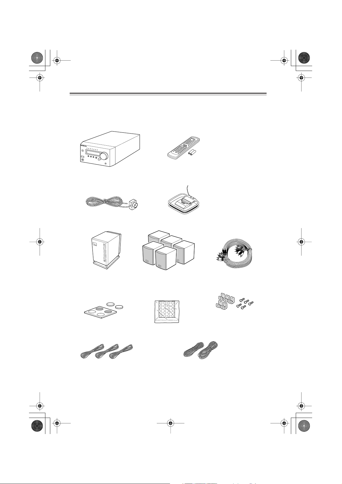
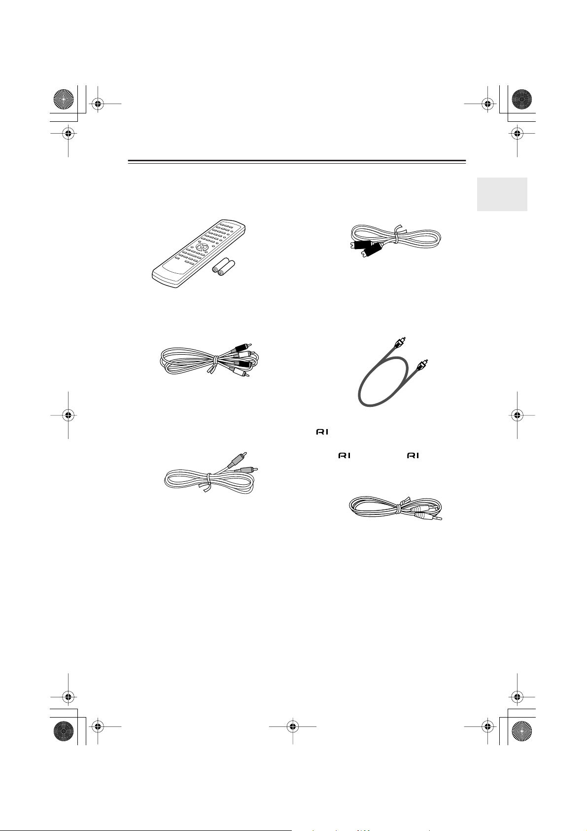
Supplied Accessories
Make sure your box contains everything listed below.
If any pieces are missing, contact the nearest Onkyo service station.
The number of each item indicated in brackets.
•AV Controller (PR-155X) [1]
• FM indoor antenna [1]
Receives FM radio signals.
• The shape may vary depending on
• Remote controller (RC-568S) [1]
Batteries (size AA/R6) [2]
• AM indoor antenna [1]
Receives AM radio signals.
the area which it was purchased.
• Subwoofer (SWA-V10X) [1] • Speakers (ST-V10X) [5]
P
O
W
E
R
S
WA
-
P
V
O
W
1
E
0
R
E
X
D
S
U
BW
O
O
F
E
R
• Subwoofer cork spacers
[1set: 4 pieces]
To be attached to the bottom
of the subwoofer.
• Speaker cork spacers
[1set: 20 pieces]
To be attached to the
bottom of the speakers.
• Instruction Manual
(this manual) [1]
• Manual for DV-S155X
[1]
• Multi-splitter cable (3m) [1]
Connects the PR-155X and
SWA-V10X.
• Speaker installation brackets [5]
and screws [5]
• Speaker cables (for front left/
right, and center) 3.5 m [3]
• Speaker cables (for surround) 8 m [2]
Note:
The HTC-V10X functions at an optimal level when the SWA-V10X subwoofer, ST-V10X
speakers, PR-155X AV controller, and DV-S155X DVD player are used together. Any malfunction that occurs when you use the PR-155X with other speakers, or use the speakers with
another amplifier, may not be covered by the warranty.
8
Page 9
HTC-V10X_En.book Page 9 Wednesday, July 21, 2004 2:49 PM
Supplied Accessories —Continued
• Remote controller for the DV-S155X
(RC-522DV) [1]
Batteries (AA/R6) [2]
•Audio connection cable 0.6 m [1]
Tr ansmits analog signals.
• Composite video cable 1.5 m [1]
Tr ansmits video signals.
•S Video connectioncable [1]
Tr ansmits S video signals.
• Optical cable 1.0 m [1]
Tr ansmits digital audio signals.
• cable 0.6 m [1]
This cable is used to connect the PR-155X and
DV-S155X.
To use , in addition to an connection,
you must make an analog audio connection
(RCA) between the PR-155X and DV-S155X.
9
Page 10
HTC-V10X_En.book Page 10 Wednesday, July 21, 2004 2:49 PM
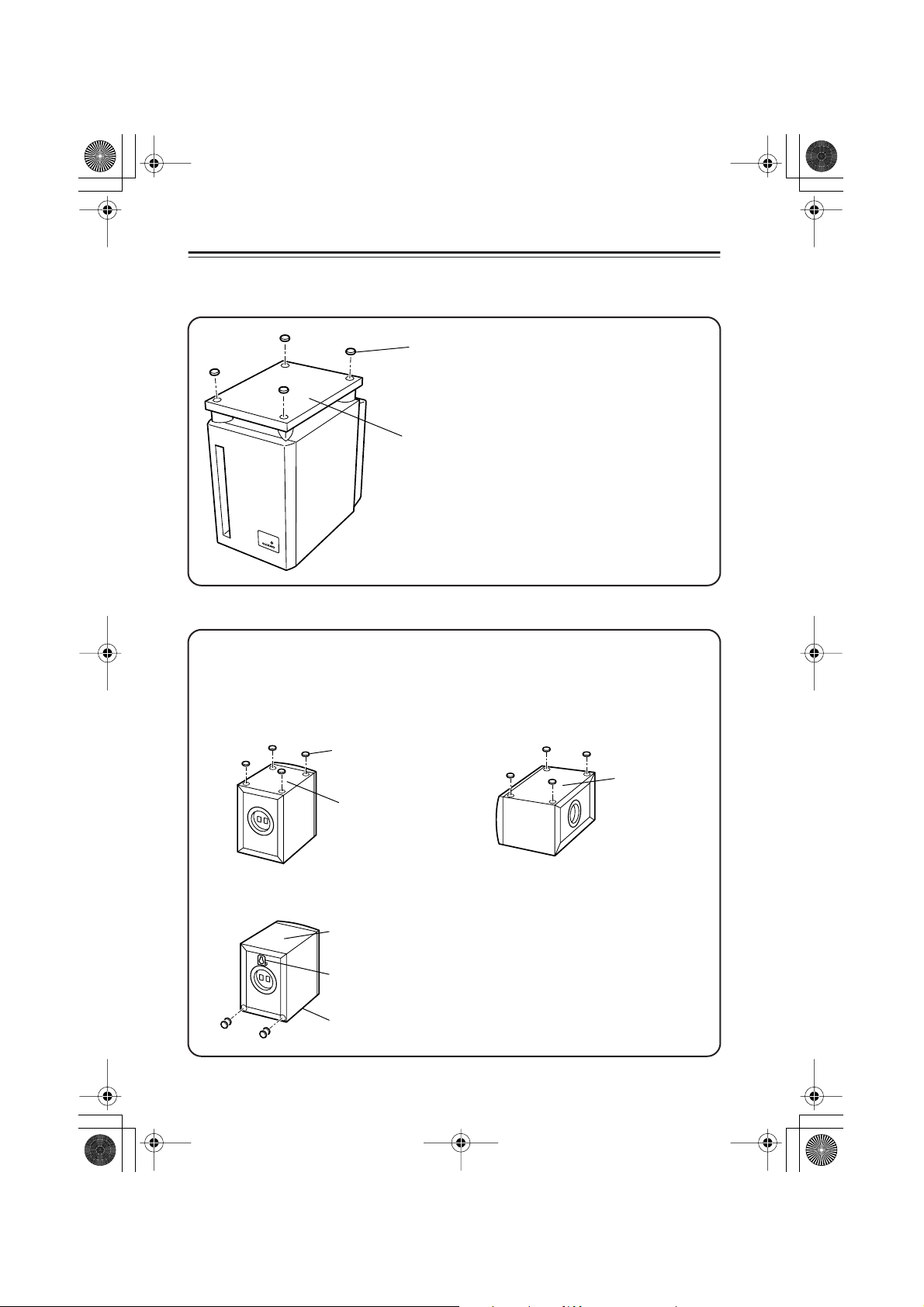
Supplied Accessories —Continued
Using the included cork spacers
• Cork spacer for the subwoofer (SWA-V10X)
■
Cork spacer
We recommend that you use the
included cork spacers so you can
enjoy superior sound.
The cork spacers also prevent the
subwoofer from slipping.
Bottom of SWA-V10X
• Cork spacers for the speakers (ST-V10X)
We recommend that you use the included cork spacers so you can enjoy superior sound.
The cork spacers also prevent the speakers from slipping.
•To mount the speakers on a wall, first read the section in the instruction manual that
describes the included installation brackets.
Positioning vertically Positioning horizontally
Cork spacer
Side of ST-V10X
Mounting on a wall
10
Bottom of ST-V10X
Bottom of ST-V10X
Installation bracket
Top of ST-V10X
Wall-mount the speakers upside
down. Layer two spacers and attach
them to two locations. The plaques
rotate so that you can position the
speakers upside down.
Page 11
■
HTC-V10X_En.book Page 11 Wednesday, July 21, 2004 2:49 PM
■
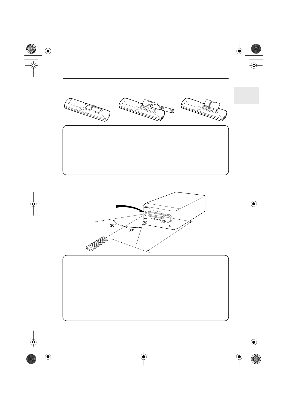
Preparing the Remote Controller
Inserting the batteries
12 3
1 Detach the battery cover.
2 Insert two size-AA/R6 batteries.
Be sure to match the + and – ends of the batteries with to diagram inside the battery
compartment.
3 Attach the battery cover.
• Do not mix new batteries with old batteries or different kinds of batteries.
•To avoid corrosion, remove the batteries if you do not intend to use the remote controller
for a long time.
Using the remote controller
PR-155X
Remote control
sensor
About 5 m (16 feet)
Point the remote controller toward the PR-155X’s remote control sensor.
• Place the unit away from strong light, such as direct sunlight or inverted fluorescent light,
which can prevent proper operation of the remote controller.
• Using another remote controller of the same type in the same room or using the unit near
equipment that uses infrared rays may cause operational interference.
• Do not put any object (such as a book) on the remote controller. The buttons of the remote
controller may be pressed by mistake, which drains the batteries.
• Make sure the audio rack doors do not have colored glass. Placing the unit behind such
doors may prevent proper remote controller operation.
• If there is an obstacle between the remote controller and the remote control sensor, the
remote controller will not operate.
11
Page 12
HTC-V10X_En.book Page 12 Wednesday, July 21, 2004 2:49 PM
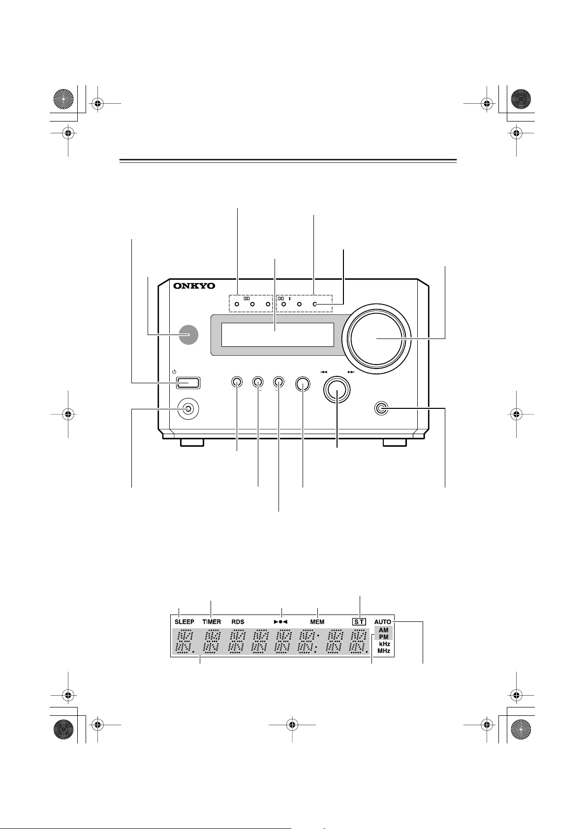
Index to Parts and Controls
Front panel
Input signal indicator (orange)
Lights up when a signal is being input.
STANDBY/ON button
Tu r ns on the power to the PR-155X
or places the unit in Standby mode.
Remote control sensor
Point the remote controller
toward the remote sensor to
operate the PR-155X. (page 11)
AV CONTROLLER
Display
DTSPCM DIGITAL DSP STEREO(GRN
Surround indicators (green)
Light up to indicate a Surround mode.
MULTI CH indicator (red)
Lights up when a multi channel signal is
being input.
PL
MULTI IN(RED
■
■
MASTER VOLUME control
Adjusts the sound level.
)
)
MASTER VOLUME
Subwoofer Level Control
(SW LVL CTRL) button
Changes the subwoofer level.
PHONES jack
This is a standard
stereo jack for connecting stereo
headphones.
Display
SLEEP indicator
Lights up when the
sleep timer is active.
STANDBY
STANDBY / ON
PHONES
SW LV L CTRL
MEMORY button
Press and hold this button while the FM/AM
indicator appears to
switch to Menu mode.
TIMER indicator
Lights up when the respective
timer is set.
Tuned indicator
MEMORY
TIMER
CLEAR
INPUT button
Selects an input source.
TIMER button
Switches the Timer mode.
INPUT
MULTI JOG
PUSH TO ENTER
MULTI JOG dial
Use this dial to select and
confirm an option.
MEM (memory)
indicator
SURROUND
-
PR
15 5
X
SURROUND
MODE button
Selects a surround mode.
ST (stereo) indicator
12
Multi-purpose display
AUTO indicatorAM/PM indicators
Page 13
HTC-V10X_En.book Page 13 Wednesday, July 21, 2004 2:49 PM
Index to Parts and Controls —Continued
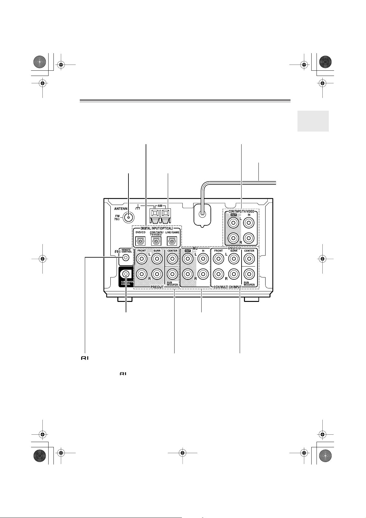
Rear panel
■
DIGITAL INPUT jacks
Using optical cables, connect these jacks
to the DV-S155X DVD player and other
components that feature digital outputs.
FM antenna connector
Connect the included FM
indoor antenna or FM
outdoor antenna here.
AM antenna connector
Connect the included AM
indoor antenna or AM outdoor antenna here.
CDR/TAPE/TV/VIDEO IN/OUT jacks
Connect these jacks to the audio input
and output jacks of a CD recorder, tape
deck, TV, and/or VCR.
Power cord
SUBWOOFER CONTROL jack
Connect this jack to the SUBWOOFER
CONTROL jack on the SWA-V10X
subwoofer, using the Multi-splitter
cable included in the package.
jack
Connect this jack to the DV-S155X to
link and control then together.
Connecting only the cable does not
link the system completely. You will also
need to connect analog audio cables.
MD IN/OUT jacks
Connect these jacks to
the audio input and output of an MD recorder.
PREOUT jacks
Connect these jacks to
the MAIN IN jacks on
the SWA-V10X subwoofer using the Multisplitter cable included in
the package.
DVD/CD input jacks
Connect these jacks to the audio
output jacks on the DVD player.
You can connect a DVD player that
supports multi channel output.
13
Page 14
HTC-V10X_En.book Page 14 Wednesday, July 21, 2004 2:49 PM
Index to Parts and Controls —Continued
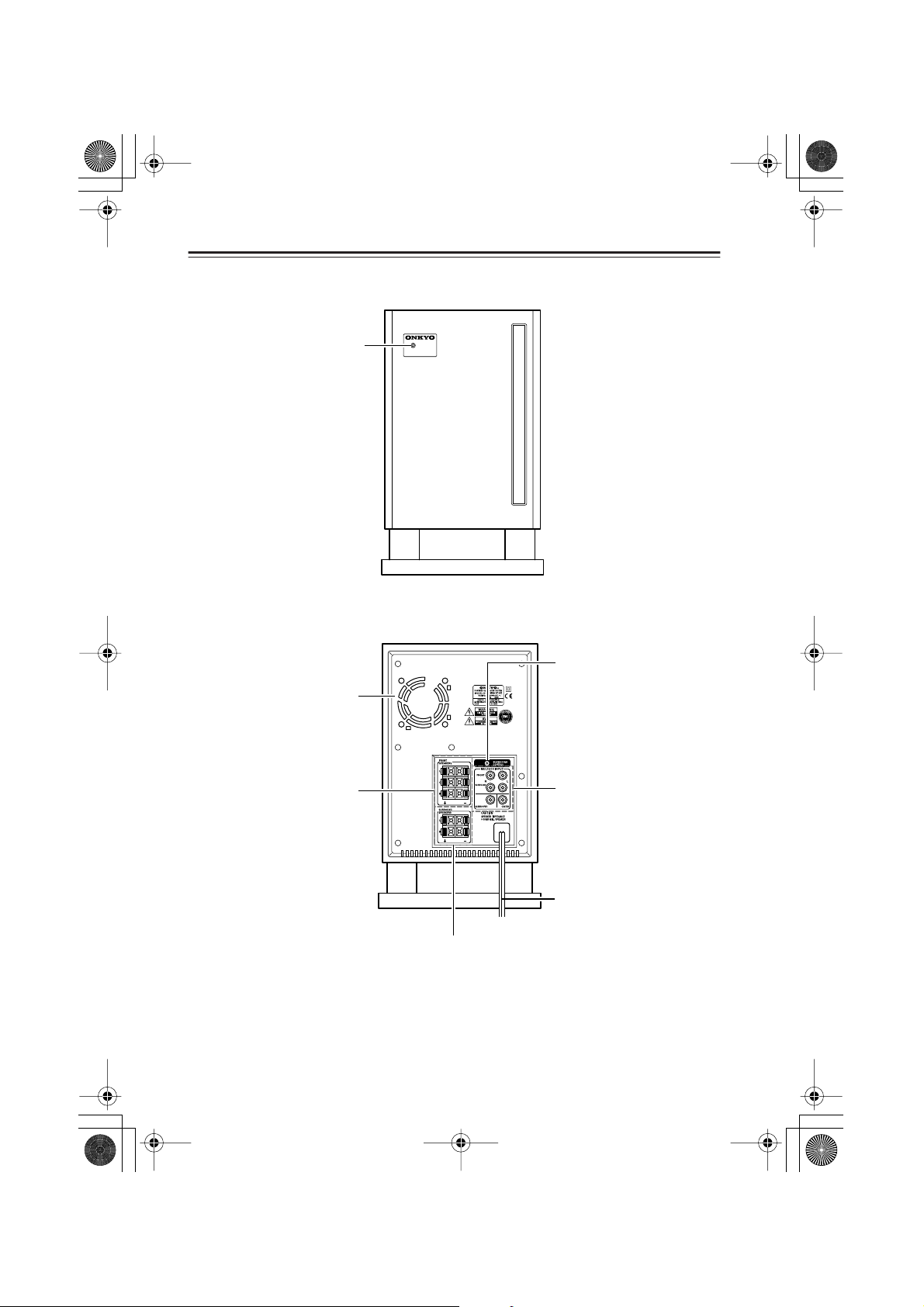
Subwoofer SWA-V10X (front panel)
POWER indicator
Lights up green when
the power is turned on.
Subwoofer SWA-V10X (rear panel)
POWER
SWA-V10X
POWERED SUBWOOFER
■
■
Cooling fan
This fan starts rotating when
the output exceeds a certain
threshold to release the heat
inside the subwoofer.
FRONT SPEAKERS connectors
Connect the front left/right
speakers to the L/R connectors and the center speaker
to the C connector.
14
SUBWOOFER CONTROL
jack
Connect this jack to the
PR-155X SUBWOOFER
CONTROL jack.
MULTI CH INPUT jacks
Connect these jacks to the
PR-155X PREOUT jacks.
Power cord
SURROUND SPEAKERS connectors
Connect the surround left/right speakers here.
Page 15
■
HTC-V10X_En.book Page 15 Wednesday, July 21, 2004 2:49 PM
Index to Parts and Controls —Continued
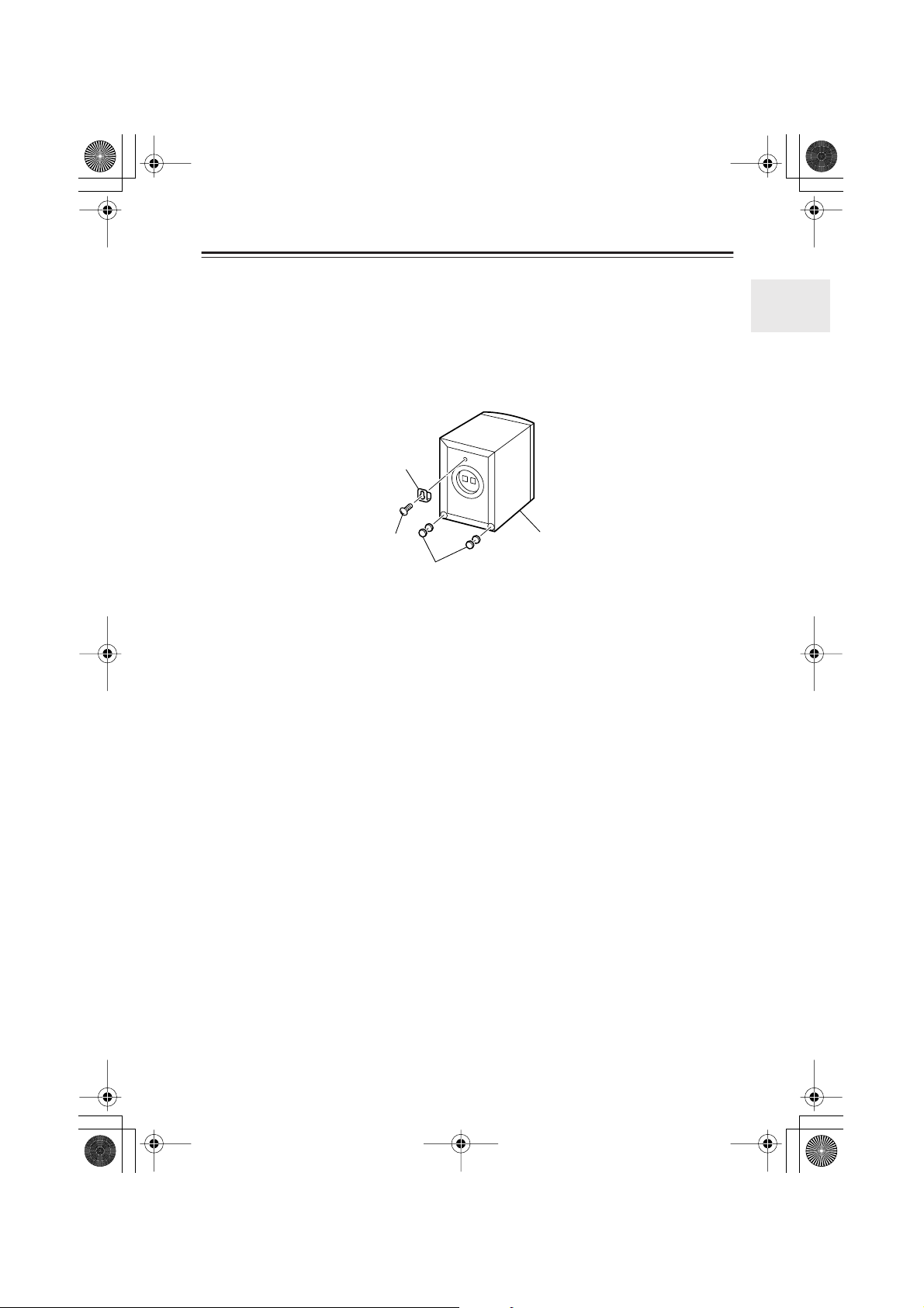
Using the installation brackets
Attaching the brackets
Wall-mount the speakers upside down. Use the included screws to attach the brackets to the
back of the speakers. To increase stability, layer two included cork spacers and attach them in
two locations as shown in the illustration. The plaques rotate to allow you to position the speakers upside down.
Installation bracket
Installation screw
Cork spacers
Caution:
Before you mount the speakers on a wall, check the strength of the wall. The supporting
strength of the screws varies depending on the wall material and the position of the studs. Use
the longest and thickest screws possible, with a head diameter of 4 mm to 10 mm and a thread
diameter of 4 mm or less. (Onkyo recommends that you consult a professional home electronics
installer.)
ST-V10X
15
Page 16
HTC-V10X_En.book Page 16 Wednesday, July 21, 2004 2:49 PM
Index to Parts and Controls —Continued
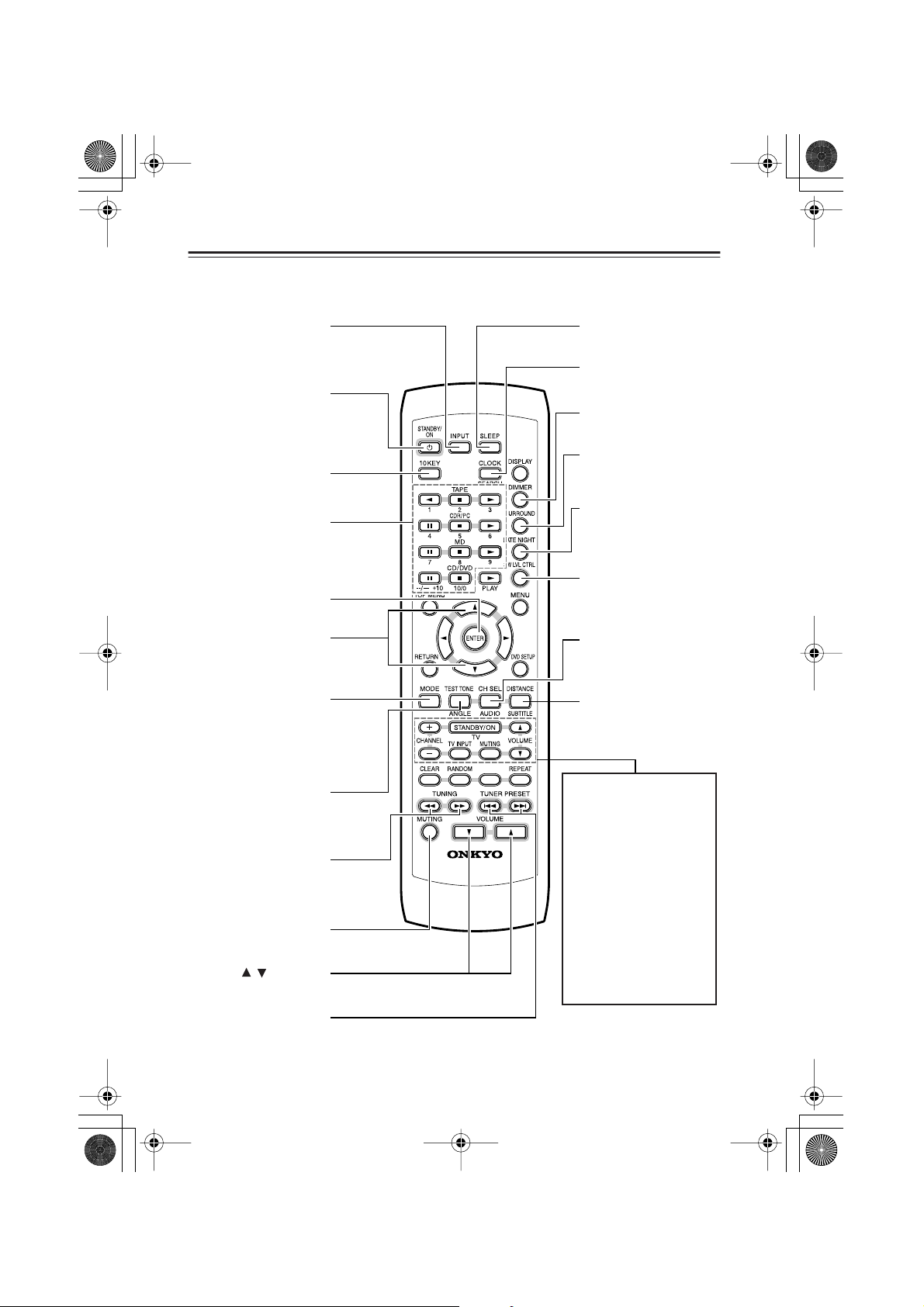
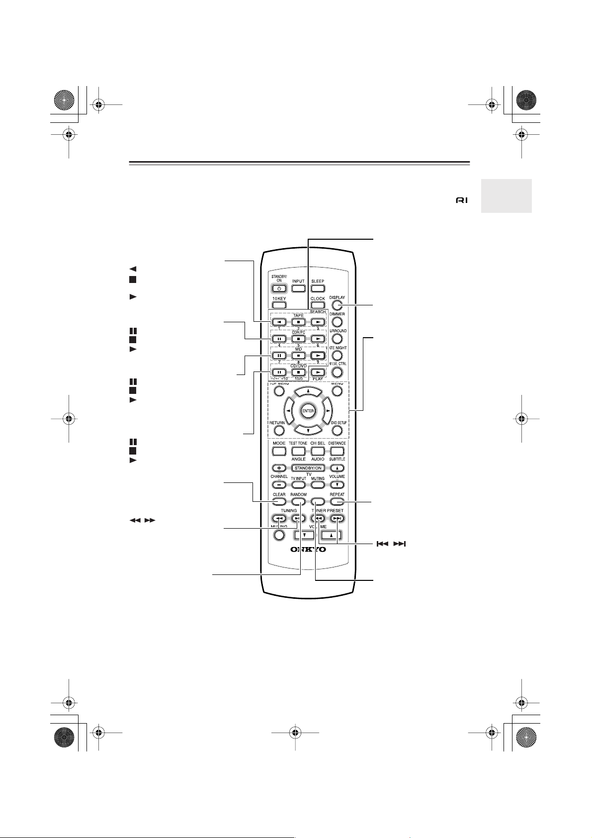
Remote controller (RC-568S)
■
INPUT button
Selects the input source.
STANDBY/ON button
Switches between power
standby and on.
10KEY button
Press this button before
pressing the number buttons.
Number buttons
Function as number buttons for 10 seconds after
you press the 10KEY button to enable you to select
a preset station, etc.
ENTER button
Confirms settings.
▲/▼ buttons
Adjust the speaker distance
and level for the speaker
settings.
MODE button
Switches between Auto and
Mono FM mode during FM
reception. During multi
channel signal input,
switches between Auto and
Multi channel input.
TEST TONE button
Outputs a test tone for setting speaker levels.
TUNING buttons
Select a station (Auto Tuning).
MUTING
Mutes the sound temporarily.
VOLUME buttons
Adjusts the volume.
/
RC-568S
SLEEP button
Sets the sleep timer.
CLOCK button
Displays the current time.
DIMMER button
Adjusts the brightness
of the front display.
SURROUND button
Selects the surround
mode.
LATE NIGHT button
Changes the dynamic
range for lower listening
volume.
SW LVL CTRL button
Adjusts the subwoofer
level.
CH SEL button
Selects a speaker for
changing its output
level.
DISTANCE button
Sets a distance for each
speaker.
MEMORY
TV operation buttons
To use these buttons, you
need to program the TV’s
remote control code. Refer to
page 64 for more information.
STANDBY/ON button
Tu r ns the TV on and off.
TV MUTING button
Mutes the TV volume.
TV CHANNEL +/– buttons
Selects a TV channel.
TV VOLUME ▲/▼ buttons
Adjusts the TV volume.
TV INPUT button
Selects the TV input.
TUNER PRESET button
Select a preset station.
16
Page 17
■
HTC-V10X_En.book Page 17 Wednesday, July 21, 2004 2:49 PM
Index to Parts and Controls —Continued
Remote controller (RC-568S)
The following buttons on the remote controller are available when the unit is connected to an
Onkyo separate collection series component (DV-S155X, K-501A or CDR-201A) via the
connector.
Number buttons
Function as number buttons
for 10 seconds after you press
the 10KEY button. While
Tape deck operation buttons
: Plays the B side of a tape.
: Stops playback, recording,
fast forward, or fast rewind.
: Plays the A side of a tape.
CDR/PC operation buttons
:Pauses playback.
: Stops playback.
: Starts playback.
MD recorder operation buttons
:Pauses playback or recording.
: Stops playback or recording.
: Starts playback or resumes
recording.
CD/DVD player operation buttons
:Pauses playback.
: Stops playback.
: Starts playback.
CLEAR button
Erases programmed tracks.
/ buttons
Fast forward / fast reverse a
DVD/CD/MD/CDR.
RANDOM button
Starts Random playback.
MEMORY
RC-568S
these buttons are functioning
as number buttons, you can
use them to select a track on
the CD player, MD recorder,
or CD recorder.
DISPLAY button
Changes the information
being displayed.
DVD player operation buttons
TOPMENU
: Displays the highest
menu screen on a
MENU: Displays a DVD
RETURN
DVDSETUP
ENTER: Confirms the set-
▲/▼/√√√√/®®
REPEAT button
Starts repeat playback.
Locate a desired track on a
DVD, CD, MD, or CDR.
MEMORY button
Press this button to start programming.
DVD.
menu screen.
: While the initial
setup screen or
menu is displayed,
pressing this button
moves the cursor to
the previous item.
: Displays the setup
screen.
ting.
®®
: Move the cursor up,
down, left, or right
to select an option.
/ buttons
For more information on each function, refer to the instruction manual for the corresponding
components.
Tip:
For 10 seconds after you press the 10KEY button, the buttons with blue labels (1–9, --/---+10,
10/0, ANGLE, AUDIO, SUBTITLE, SEARCH) will assume the function indicated below them.
17
Page 18
■
HTC-V10X_En.book Page 18 Wednesday, July 21, 2004 2:49 PM
What is Home Theater?
Enjoying home theater
The HTC-V10X creates a three-dimensional audio experience by moving and panning sound
among multiple speakers. This enables you to enjoy the atmosphere and acoustics of theaters
and concert halls (i.e., 5.1 channel surround playback) while you relax at home.
All speakers have the same features. Two speakers serve as the front left and right speakers. One
speaker serves as the center speaker, and two speakers serve as the surround left and right
speakers.
Depending on the audio-encoding of a particular DVD disc, you can enjoy DTS or Dolby Digital playback. You can also enjoy Onkyo’s proprietary DSP surround sound for TV or MD playback (see page 35).
Front speakers
Output complete audio signals. In the 5.1ch environment, they
serve as posts that support the acoustic field.
Subwoofer
Outputs only the bass
range sound.
Center speaker
Outputs tight audio, clearly
framing the acoustic field. In
movies, dialog and narration are generally output.
Surround speakers
Add a realistic theater atmosphere and convey
3D sound movements and special audio effects.
Connecting the HTC-V10X
• Connect the AV Controller (PR-155X) and the subwoofer (SWA-V10X) (page 19).
• Connect the subwoofer (SWA-V10X) and the speakers (ST-V10X) (page 20).
• Connect the AV Controller (PR-155X) and the DVD player (DV-S155X) (page 22).
• Connect your MD recorder or CD recorder to the PR-155X to play an MD or CD in a 5.1ch
environment (pages 23–24).
Positioning the speakers
Refer to the explanation of each speaker’s role and the speaker position examples (page 21).
Setting up the speakers
To enjoy optimal surround sound, set up the speakers correctly (pages 62–63).
18
Page 19
Incomplete
Insert completely
■
HTC-V10X_En.book Page 19 Wednesday, July 21, 2004 2:49 PM
Connections
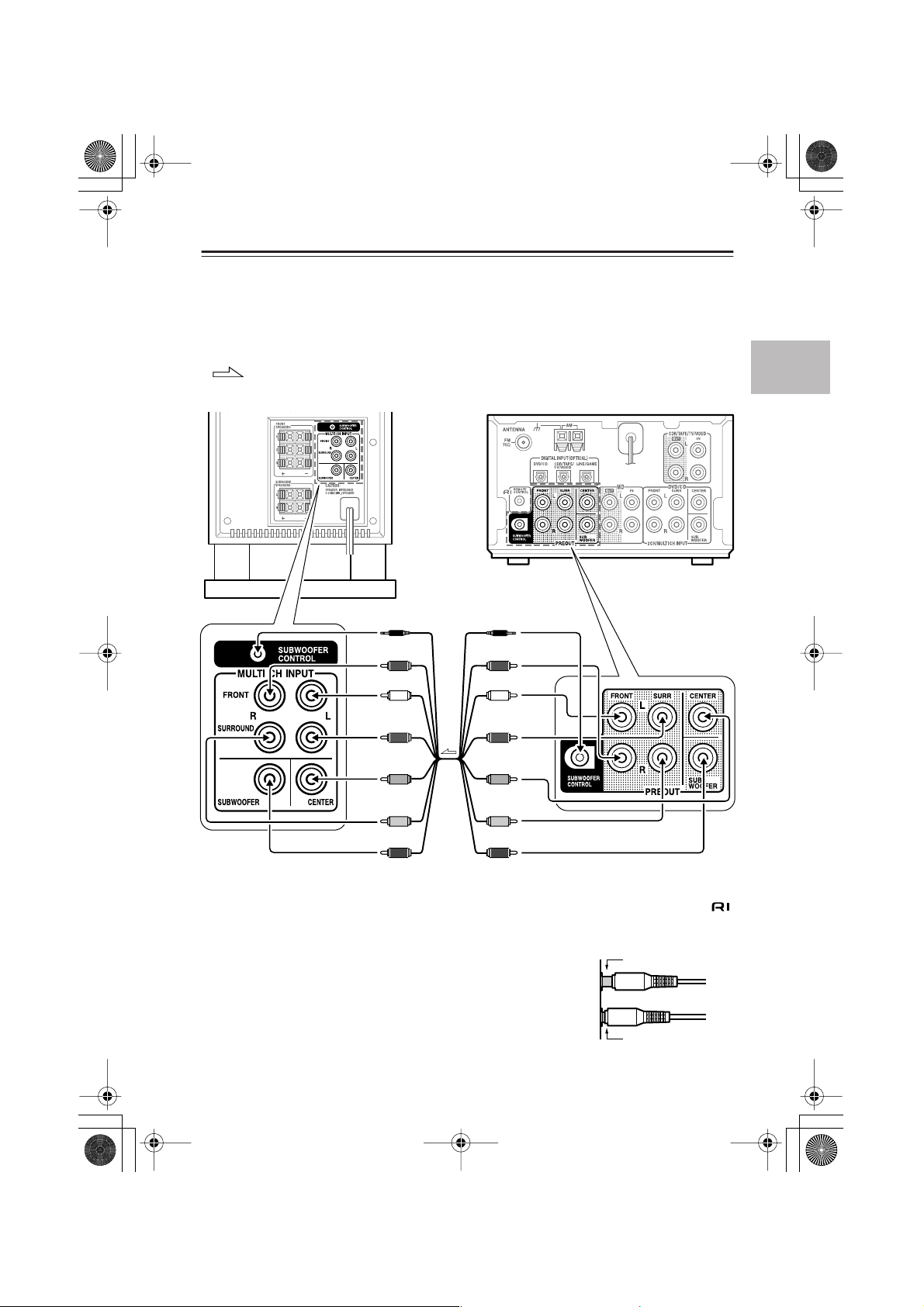
Connecting the AV Controller (PR-155X) and the subwoofer (SWAV10X)
Refer to the diagram below to connect the jacks using the included multi-splitter cable.
Do not connect the power plug yet.
: signal flow
SWA-V10X
PR-155X
SUBWOOFER
CONTROL (black)
FRONT R (red) FRONT R (red)
FRONT L (white)
SURR L (blue) SURR L (blue)
CENTER (green)
SURR R (grey) SURR R (grey)
SUBWOOFER (purple) SUBWOOFER (purple)
To SWA-V10X’s MAIN IN jack To PR-155X’s PRE OUT jack
SUBWOOFER
CONTROL (black)
FRONT L (white)
CENTER (green)
Be sure to use the SUBWOOFER CONTROL jack. Do not confuse this jack with the
REMOTE CONTROL jack.
• Plug in all cables completely. Otherwise, noise or malfunction
may occur.
• Do not bundle the multi-splitter cable with the speaker cables.
Otherwise, tonal quality may deteriorate.
19
Page 20
■
HTC-V10X_En.book Page 20 Wednesday, July 21, 2004 2:49 PM
Connections —Continued
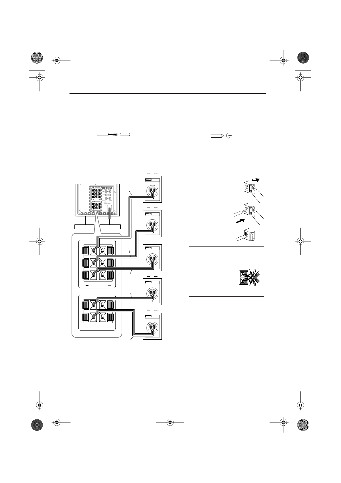
Connecting the subwoofer (SWA-V10X) and the speakers (ST-V10X)
Before connecting the speakers
Prepare the included speaker cables as follows:
1 Remove the tip of the plastic shield of the speaker cables. 2 Twist the core wires.
Connecting the front, center, and surround speakers
All the ST-V10X speakers have the same features. Two speakers serve as the front left and right
speakers; one speaker serves as the center speaker; and two speakers serve as the surround left
and right speakers.
Connecting the cords to the
SWA-V10X
FRONT
SPEAKERS
L
C
R
SURROUND
SPEAKERS
L
white
green
red
blue
MODEL
Front left
speaker
(ST-V10X)
MODEL
Center
speaker
(ST-V10X)
MODEL
Front right
speaker
(ST-V10X)
MODEL
Surround left
speaker
(ST-V10X)
speaker connectors:
1 Press the lever.
2Insert the core
wires into the
slot.
3 Release the lever.
WARNING!
To prevent any circuit malfunction, do
not let the core
wires of the + and –
(or L and R) cords
contact each other.
NO
R
gray
MODEL
Surround right
speaker
(ST-V10X)
• Connect the speaker’s “+” connector to the subwoofer’s “+” connector, and the speaker’s
“–” connector to the subwoofer’s “–” connector using the color-coded speaker cables.
• Connect the colored speaker cables to the “+” connectors.
• If you connect the cords to the wrong connectors (“+” to “–”) or connect the speakers to the
wrong channels (L to R), the audio will sound unnatural.
20
Page 21
HTC-V10X_En.book Page 21 Wednesday, July 21, 2004 2:49 PM
Connections —Continued
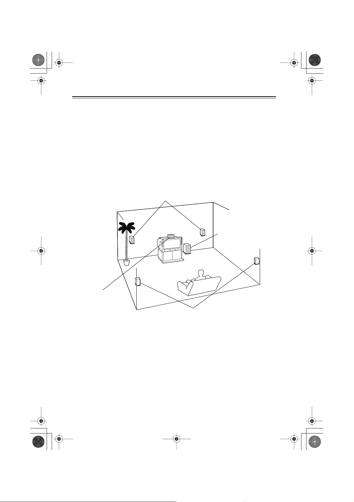
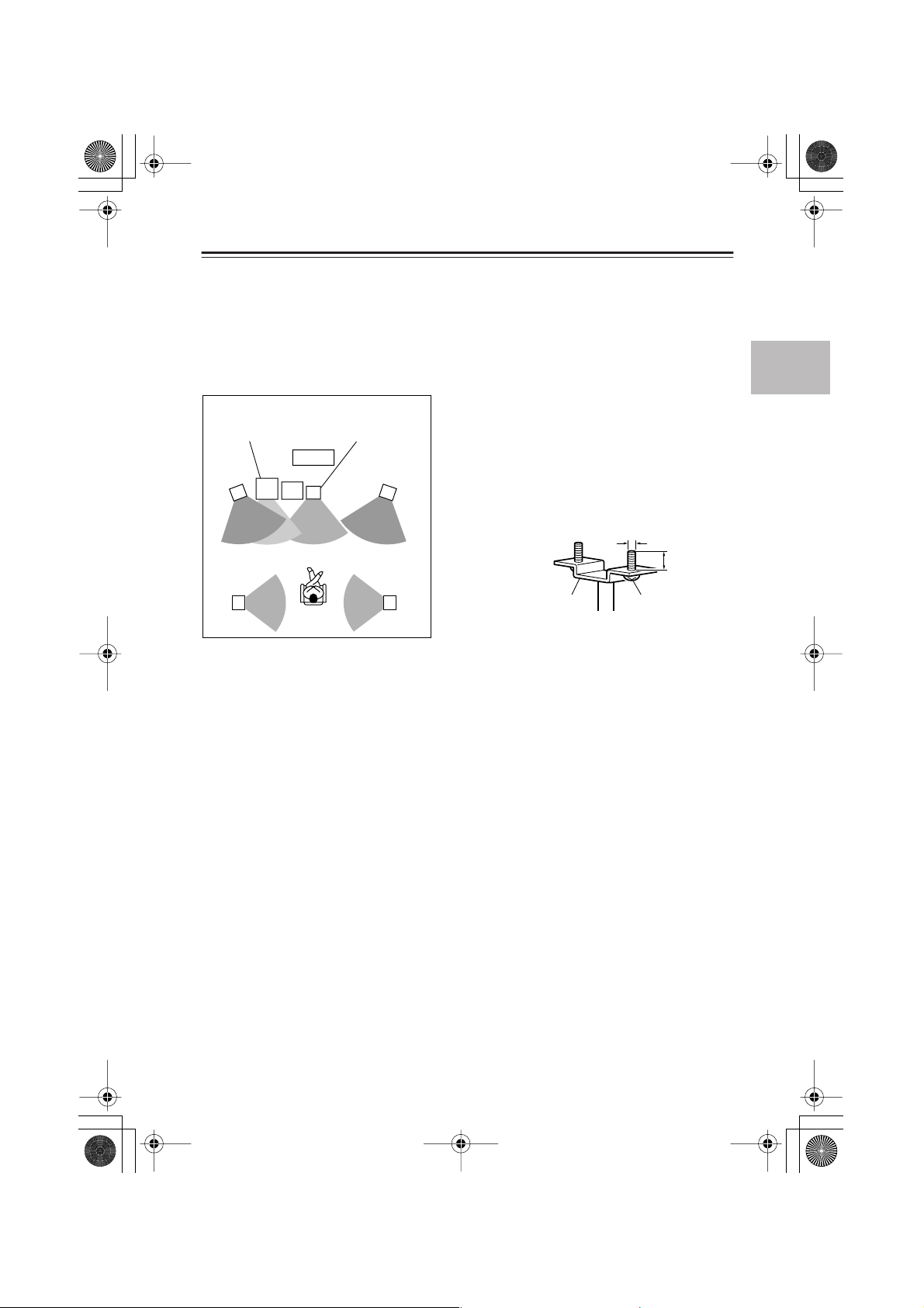
Basic positioning example and the role of each speaker
Although recommended speaker positions vary depending on the room size and wall material,
this section offers a basic positioning example and explains the function of each speaker.
Even if you cannot precisely follow the example below, you can still enjoy optimal surround
sound by specifying the distance from the listener to the speakers (page 62). You can also adjust
the volume level of each speaker to suit your preference (page 63). (Make these settings after all
connections are completed.)
Speaker Setup Example
Subwoofer
SWA-V10X
Front left
speaker
ST-V10X
TV
PR-155X
Center speaker
ST-V10X
Front right
speaker
ST-V10X
Using optional speaker stands or brackets
Each satellite speaker has one M5 screw hole on the
back, and two 60 mm M5 screw holes on the bottom. To secure the bottom surface, use optional
stands or brackets.
If you use a stand or brackets, use M5 screws with
an effective screw length of 7–12 mm, depending on
the thickness of the stand.
5 mm
Surround left
speaker
ST-V10X ST-V10X
Listening
position
Surround right
speaker
Bracket (available
at hardware stores)
Wall-mounting the speakers
7–12 mm
M5 screw
Use the included wall-mount brackets (page 15).
Center speaker
Place the center speaker as close as possible to the screen and position it so that the sound is
directed at the listener’s ears.
The center speaker enriches the sound image by framing the sound effects and panning sound
output from the front left and right speakers. In movies, generally, dialog and narration are output from this speaker.
Front left and right speakers
Place the front speakers in front of the listener.
• Position the speakers at the same height as the center speaker.
• Position the speakers so that the audio will be directed at the listener’s ears. It is recommended that you place the speakers symmetrically.
Surround speakers
Place the surround speakers to the sides or rear of the listener.
The surround speakers enhance the atmosphere of theaters or halls by conveying the threedimensional movement of sound and re-producing environmental sounds (that represent the
background) and special effect sounds (for example, that bring a scene to a climax).
Subwoofer
Place the subwoofer near the front speakers.
The subwoofer has a great advantage in producing powerful, super bass effects.
Locate the subwoofer at about one-third the width of the wall for a better bass sound.
Caution:
Do not place the satellite speakers on the edge of a desk or rack. Otherwise, they may fall, causing injury.
21
Page 22
Incomplete
Insert completely
■
■
HTC-V10X_En.book Page 22 Wednesday, July 21, 2004 2:49 PM
Connections —Continued
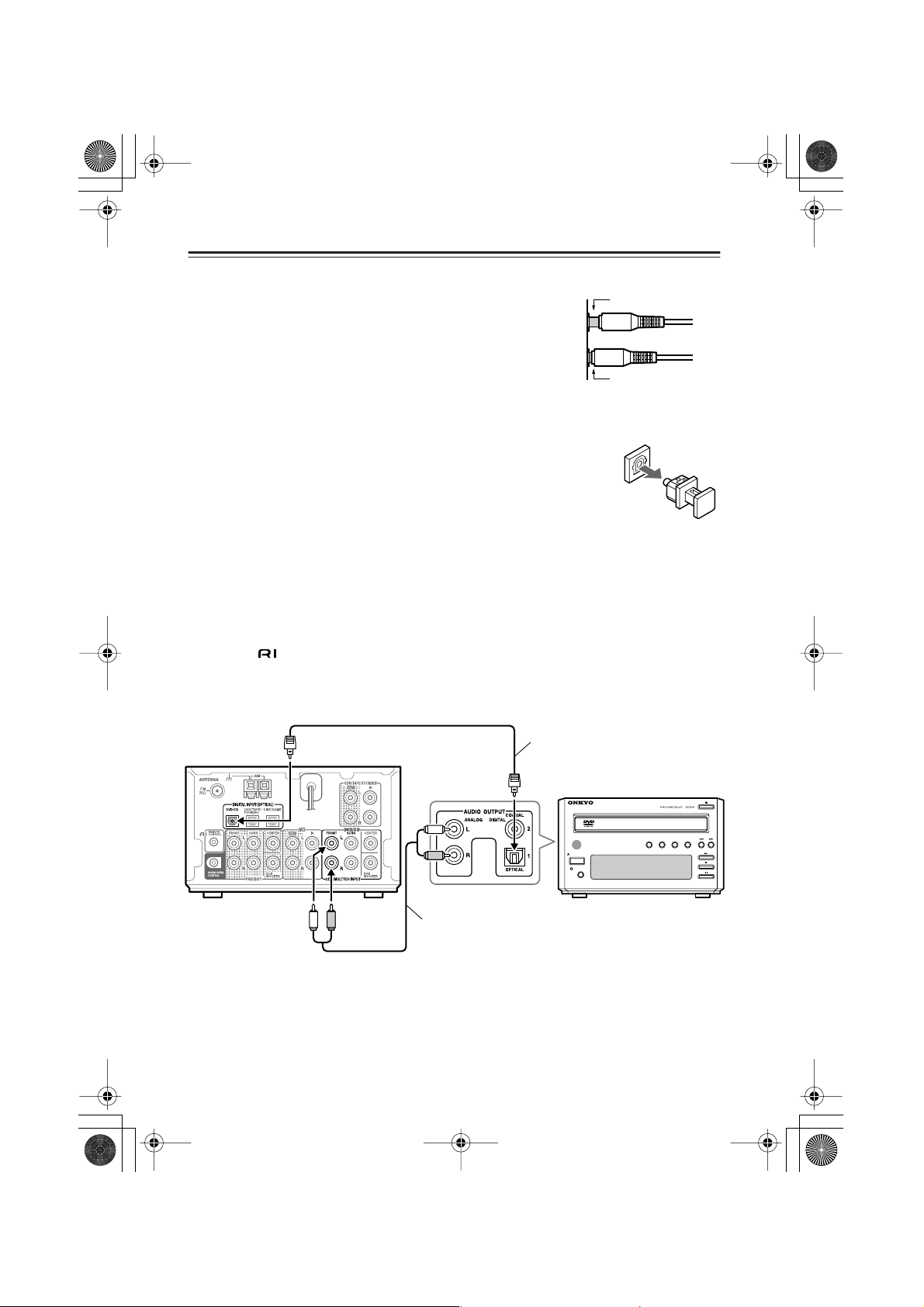
Before making connections
• Be sure to insert the cable plugs completely into the jacks. If
the connection is incomplete, noise or malfunction may occur.
• Do not bundle the audio connection cables with the power
cable and/or speaker cables. Otherwise, tonal quality may deteriorate.
• When you use an optical cable, do not bend or coil it tightly.
Otherwise, noise or malfunction may occur.
• After all connections are completed, insert the power cable
plug into the appropriate AC outlet (page 30).
• The DIGITAL INPUT jack has a protective cap installed. When you use
this jack, remove the cap. When you are not using this jack, be sure to
replace the cap.
Connecting the AV controller (PR-155X) and the DVD player (DVS155X)
You can connect the audio output from the DV-S155X to these jacks.
Connect the PR-155X DIGITAL INPUT (OPTICAL) DVD/CD jack to the DV-S155X DIGITAL OUTPUT jack using the included optical cable.
To make an connection to other Onkyo components, connect the PR-155X DVD/CD 2CH
INPUT jacks to the DV-S155X AUDIO OUTPUT L/R jacks using an audio connection cable.
Connect the video output from the DVD player directly to the TV.
22
PR-155X
Audio connection cable
Optical cable
STANDBY
/
ON
STANDBY
DISPLAY
DVD PLAYER
REPEAT
DV-S155X
DIMMERPROGRESSIVERANDOM
DV-S
155X
Page 23
■
HTC-V10X_En.book Page 23 Wednesday, July 21, 2004 2:49 PM
Connections —Continued
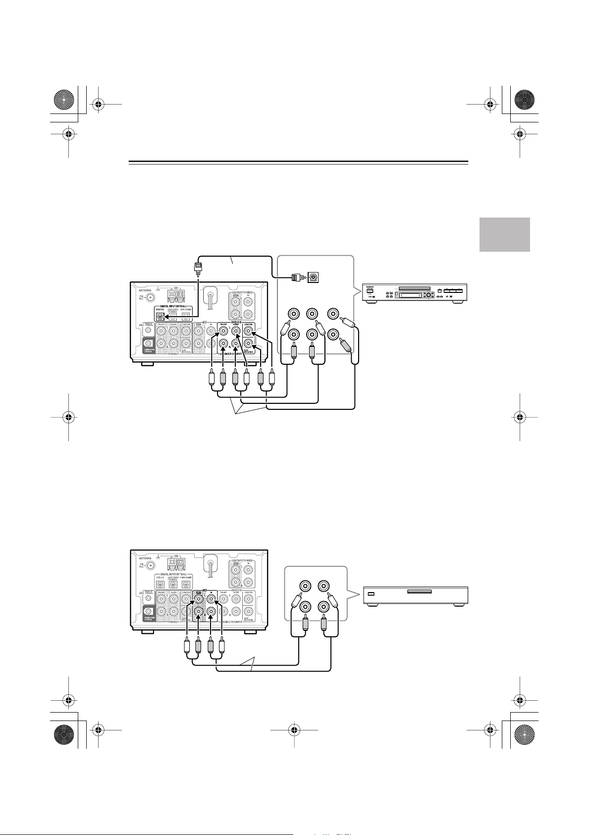
Connecting an optional DVD player that supports analog multi channel playback
Connect the PR-155X DIGITAL INPUT (OPTICAL) jack (DVD/CD) to the optical digital output jack on a DVD player using an optical cable. Also, connect the PR-155X MULTI CH
INPUT jacks to the multi-audio output jacks on the DVD player using audio connection cables
or analog multi channel cables.
(DVD Audio and Super Audio CDs will output only analog audio. Be sure to make both analog
and digital connections.) You must also change the multi channel output setting (page 33).
Option cable
DIGITAL
OUTPUT
PR-155X
PROGRESSIVE
TOP MENU MENU
S
O
R
R
U
FRONT
OUTPUT
MULTI
SURR CENTER
L
R
SUB
WOOFER
PROGRESSIVE SCAN
RETURN SETUP
C
P
U
R
S
E
T
H
N
T
E
O
SUPER AUDIO CD & DVD AUDIO / VIDEO PLAYER
DV-SP502
Audio connection cables
Connecting an MD recorder (MD jacks)
You can connect the MD jacks to the audio input/output on an MD recorder. (The following figure illustrates how to connect an optional Onkyo component.)
Connect the PR-155X MD IN jacks to the audio output jacks on an MD recorder using an audio
connection cable.
Connect the PR-155X MD OUT jacks to the audio input jacks on the MD recorder using an
audio connection cable.
Since audio data is recorded on two channels on an MD, Dolby digital and other digital audio
playback are unavailable through this connection, even if the connection is digital. However,
you can enjoy surround sound, such as Dolby Pro Logic II, using only an analog connection.
PR-155X
Audio connection
cables
AUDIO
IN
AUDIO
OUT
L
R
23
Page 24

■
HTC-V10X_En.book Page 24 Wednesday, July 21, 2004 2:49 PM
Connections —Continued
Connecting a CD recorder, tape deck, or VCR (CDR/TAPE/TV/VIDEO
jacks)
You can connect the audio input and output of a CD recorder, tape deck, TV, or VCR to these
jacks. Connect the video output from the VCR directly to the TV.
(The following illustration is an example of connecting optional Onkyo products.)
Connect the PR-155X’s CDR/TAPE/TV/VIDEO IN jacks to the audio output jacks of the connecting component, using an audio connection cable.
To connect a recording component, connect the PR-155X CDR/TAPE/TV/VIDEO OUT jacks
to the audio input jacks on the connecting component using an audio connection cable.
To listen to digital playback from the connected component, connect the PR-155X DIGITAL
INPUT (OPTICAL) CDR/TAPE/TV/VIDEO jack to the digital audio output of the connecting
component using an optical cable.
To connect an Onkyo CDR-201A, connect the PR-155X to the DIGITAL OUTPUT 2 jacks on
the CDR-201A.
• Since audio data is recorded on two channels on a CD-R, CD, or cassette tape, Dolby digital
and other digital audio playback is unavailable through this connection, even if the connection is digital. However, you can enjoy surround sound, such as Dolby Pro Logic II, using
only an analog connection.
•To connect -compatible Onkyo components, you will need to make an appropriate input
source setting on each component (page 32).
PR-155X
24
Optical cable
Audio connection cable
AUDIO
IN
DIGITAL
OUTPUT
L
R
AUDIO
OUT
STANDBY / ON
DISPLAY
AUDIO CD RECORDER
MULTI JOG
CD
INPUT
STANDBY
EDIT / NO YES
REC
FINALIZE
DUBBING
PUSH TO ENTER
CDR-201A
Page 25

■
■
HTC-V10X_En.book Page 25 Wednesday, July 21, 2004 2:49 PM
Connections —Continued
Listening to TV surround sound (CDR/TAPE/TV/VIDEO jack)
Connect the PR-155X DIGITAL INPUT (OPTICAL) CDR/TAPE/TV/VIDEO jack to the digital audio output on the TV using an optical cable.
If the TV does not feature a digital audio output jack, connect the PR-155X CDR/TAPE/TV/
VIDEO IN jacks to the analog audio output on the TV using an audio connection cable.
PR-155X
Optical cable
Audio
output
L
R
Digital
output
Connecting to other digital components (DIGITAL INPUT (OPTICAL)
LINE/GAME jack)
You can connect this jack to a personal computer or game machine that features a digital audio
output.
Connect the PR-155X DIGITAL INPUT (OPTICAL) LINE/GAME jack to the digital output on
your personal computer or game machine using an optical cable. If your personal computer
does not feature an optical digital output, you can install an audio processor card to make a digital connection available.
Tip:
Check the digital audio output setting of the connecting device. The Dolby Digital or DTS signal output setting on some of DVD-compatible game machines may be set to off.
PR-155X
Optical cable
Digital
output
Game machine
Personal computer
25
Page 26

■
HTC-V10X_En.book Page 26 Wednesday, July 21, 2004 2:49 PM
Connections —Continued
About System functions ( functions)
If you connect Onkyo sepatate collection series components using the cables and audio
connection cables, you can use the following system functions. An cable is a special system
cable designed for use with Onkyo products.
Connecting the Onkyo sepatate collection series DVD player, MD recorder and CD recorder:
Connecting the system components
(Connecting the Onkyo sepatate collection series components)
Auto Power On
When you turn on the power to or start playing one of the components connected to the PR-155X, the PR155X turns on automatically. When you turn the power to the PR-155X on or off, all connected components also turn on or off respectively.
Direct Change
When you start playback on a component connected to the PR-155X, the PR-155X automatically selects
the component as the input source.
Remote Controller Operation
You can operate the components connected
to the PR-155X using the supplied remote
controller.
Program Timer
You can program a timer on the PR-155X so
that playback or recording will start automatically on the specified component at the
specified time.
CD Synchro Recording
If you set the CD recorder in Record Ready
mode, starting playback the CD will automatically start recording.
Refer to pages 19–25 for more information.
Refer to page 17 for more information.
Refer to page 50 for more information.
Refer to the instruction manual for the CD
recorder for more information.
• Incorrect connections will not enable system functions. Refer to pages 19–25 and connect the
audio connection cables and cables correctly.
• Refer to the instruction manuals for the connected components for more information on system functions.
26
Page 27

■
HTC-V10X_En.book Page 27 Wednesday, July 21, 2004 2:49 PM
Connections —Continued
Connecting an cable
If you are using an Onkyo product that has an jack, you can use the system functions.
• Use the included remote controller to operate the system functions. Point the remote control-
ler toward the remote sensor of the PR-155X.
• Please refer to the instruction manual for each component when you make connections.
Example
PR-155X (AV controller)
AV CONTROLLER
STANDBY
SW LV L CTRL
STANDBY / ON
PHONES
CD recorder (CDR-201A), etc.
AUDIO CD RECORDER
INPUT
STANDBY / ON
STANDBY
DISPLAY
DVD player (DV-S155X)
DVD PLAYER
STANDBY
/
ON
STANDBY
DISPLAY
DTSPCM DIGITAL DSP STEREO
MEMORY
TIMER
CLEAR
(
)
GRN
PL
FINALIZE
MASTER VOLUME
(
)
MULTI IN
RED
INPUT
MULTI JOG
SURROUND
PUSH TO ENTER
CD
EDIT / NO YES
REC
DUBBING
DIMMERPROGRESSIVERANDOM
REPEAT
PR
MULTI JOG
PUSH TO ENTER
CDR-201A
DV-S
-
155X
155X
• Use the jack to connect an Onkyo component that has an jack.
• If the device has two jacks, each jack has the same function. You can use either one of
them.
•Just connecting an cable does not enable the system functions. Make sure to
connect the audio connection cables correctly.
27
Page 28

■
■
HTC-V10X_En.book Page 28 Wednesday, July 21, 2004 2:49 PM
Connections —Continued
Connecting the supplied FM and AM indoor antennas (aerials)
AM indoor antenna (aerial)
FM indoor
antenna (aerial)
Insert into the hole.
Push up and
hold the lever.
Insert the end
of the cord.
Release the lever to
secure the connection.
Adjusting the position of the FM indoor antenna (aerial)
While listening to an FM program, extend the antenna (aerial) and move it in various directions
until the clearest signal is received. Then secure the antenna (aerial) with push pins in the position with the least distortion.
Adjusting the position of the AM indoor antenna (aerial)
While listening to an AM program, set the antenna (aerial) in the direction and position where
you receive the clearest sound.
Position it as far away as possible from the unit, TVs, speaker cables, and power cords (mains
leads).
Note:
Insert one end of the AM antenna (aerial) cord into either AM antenna (aerial) connector, and
the other end into the other connector. There is no difference between one end of the AM
antenna (aerial) cord and the other end — unlike the speaker cables, which have positive and
negative poles.
Connecting an AM outdoor antenna (aerial)
An outdoor antenna (aerial) will be more
effective if it is stretched horizontally above
a window or outside.
Leave the supplied AM indoor antenna
(aerial) connected.
AM indoor antenna
(aerial)
Note:
To avoid the risk of lightning and electrical
shock, grounding is necessary.
28
Outdoor antenna (aerial)
insulated
antenna cable
Page 29

HTC-V10X_En.book Page 29 Wednesday, July 21, 2004 2:49 PM
Connections —Continued
Directional Iinkage
Do not use the same antenna (aerial) for both
FM and TV (or VCR) reception, since the FM
and TV (or VCR) signals can interfere with
each other. If you must use a common FM/TV
(or VCR) antenna (aerial), use a directional
linkage type splitter.
■
To AV Controller
Directional linkage
type splitter
To TV (or VCR)
29
Page 30

■
■
HTC-V10X_En.book Page 30 Wednesday, July 21, 2004 2:49 PM
Turning on the PR-155X
Before plugging in the PR-155X
Make sure that all connections explained on pages 19–25 are complete (the connection to the
TV is required).
Turning on the PR-155X may cause a momentary power surge, which might interfere with other
electrical equipment, such as computers. If this happens, connect the power cable to a wall outlet on a different circuit.
Tip:
Do not place the DV-S155X or CD recorder on top of the PR-155X, since they tend to become
heated.
Turning on the PR-155X
Display
AV CONTROLLER
DTSPCM DIGITAL DSP STEREO
(
)
GRN
PL
MULTI IN
MASTER VOLUME
(
)
RED
STANDBY/
ON
STANDBY/ON
STANDBY
STANDBY / ON
PHONES
SW LV L CTRL
MEMORY
CLEAR
INPUT
TIMER
MULTI JOG
PUSH TO ENTER
SURROUND
-
PR
155X
The remote controller buttons used in the following step are illustrated inside a gray rectangle
().
STANDBY
STANDBY / ON
Press STANDBY/ON on the PR-155X or the
remote controller to turn on the power to the
PR-155X.
The display and indicators on the PR-155X lights up
and the POWER indicator of the subwoofer (SWA-
PR-155X
V10X) lights up.
30
Page 31
■
■
HTC-V10X_En.book Page 31 Wednesday, July 21, 2004 2:49 PM
Setup
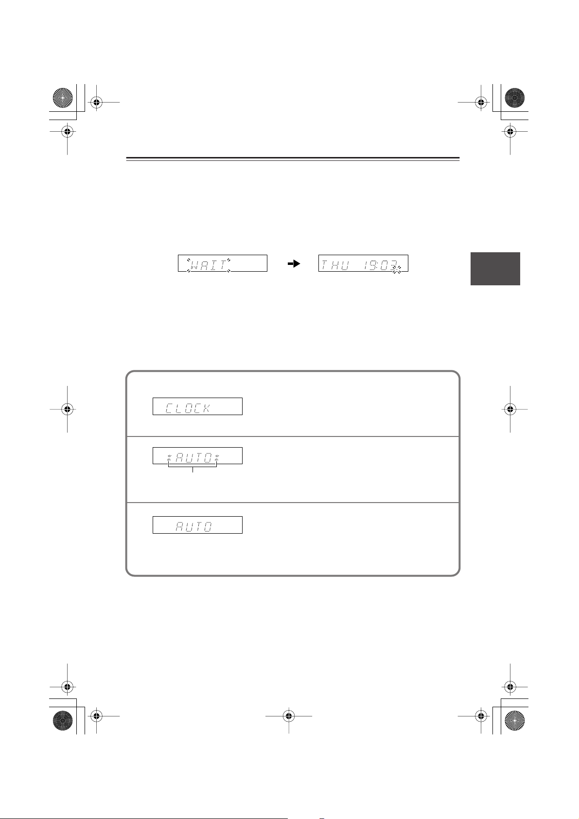
First Time Setup (for European models)
The very first time you turn on the PR-155X, the ACCUCLOCK function automatically sets the
clock by using the CT (Clock Time) information present in RDS radio broadcasts. While the
clock is being set, “WAIT” flashes on the display, as shown. It may take up to five minutes to set
the clock.
When the clock has been set, the message “CLOCK ADJUSTED” scrolls across the display,
then the day and time are displayed for a while, as shown.
The ACCUCLOCK function automatically updates the clock daily at 2 A.M., 3 A.M. and 2
P.M..
If the clock has not been set correctly, see “Setting the Time” on page 47.
Turning Off ACCUCLOCK
If you don’t want ACCUCLOCK to automatically update the clock at 2 A.M., 3 A.M. and 2
P.M. everyday, you can turn it off as follows.
1
2
These asterisks appear when
the ACCUCLOCK function is on.
3
Press TIMER button repeatedly until “CLOCK”
appears on the display, as shown.
Press MULTI JOG.
“*AUTO*” appears on the display, as shown. If
“MANUAL” appears, rotate MULTI JOG to select
“*AUTO*”.
To turn off ACCUCLOCK, press MEMORY button.
The asterisks disappear, indicating that the ACCUCLOCK function is off. To turn the ACCUCLOCK
function on again, press MEMORY button so that
asterisks appear.
31
Page 32

■
HTC-V10X_En.book Page 32 Wednesday, July 21, 2004 2:49 PM
Setup —Continued
Changing the input source setting
If you have connected an component (excluding the DV-S155X) to the DVD/CD or CDR/
TAPE/TV/VIDEO jacks, you must change the input source setting for the system to function correctly. If you have connected a game machine to the LINE jack, you may switch the
input source setting to the connected component.
AV CONTROLLER
DTSPCM DIGITAL DSP STEREO
PL
STANDBY
SW LV L CTRL
MEMORY
STANDBY / ON
PHONES
TIMER
CLEAR
21 3,4
Example: Switching from “CDR” to “TAPE”:
INPUT
1
MEMORY
2
MULTI JOG
3
PUSH TO ENTER
(
)
GRN
MASTER VOLUME
(
)
MULTI IN
RED
INPUT
MULTI JOG
SURROUND
PUSH TO ENTER
-
PR
155X
Press INPUT to display the current
input source.
The unit displays the current input source
(CDR).
Press MEMORY to display the
parameter.
The unit displays “NAME SEL” for one
second.
Rotate MULTI JOG to select the connected component.
In this example, select “TAPE.”
CDR TAPE
VIDEO TV
LINE GAME
DVD DVD M, In CD
(See the
next page.)
32
4
MULTI JOG
PUSH TO ENTER
Press MULTI JOG.
The unit displays “COMPLETE” and the
input source changes accordingly.
Page 33

■
HTC-V10X_En.book Page 33 Wednesday, July 21, 2004 2:49 PM
Setup —Continued
Setting the multi channel audio output
You do not need to set the multi channel audio output if you are using the DV-S155X.
If you have connected an optional DVD player (that supports multi channel audio on DVD
Audio or Super Audio CDs) via analog multi channel connection, you need to set the multi
channel output on the PR-155X.
STANDBY
STANDBY / ON
PHONES
AV CONTROLLER
SW LV L CTRL
DTSPCM DIGITAL DSP STEREO
MEMORY
CLEAR
(
)
GRN
PL
MULTI IN
INPUT
TIMER
(
)
RED
MULTI JOG
PUSH TO ENTER
MASTER VOLUME
SURROUND
-
PR
155X
21 3,4
INPUT
1
MEMORY
2
MULTI JOG
3
PUSH TO ENTER
Press INPUT repeatedly to display “DVD.”
Press MEMORY to display “NAME SEL.”
The unit displays “NAME SEL” for one second.
Rotate MULTI JOG to display “DVD M. In.”
DVD: Select this option if you have connected a DVD player
that does not support analog multi channel audio. (This
is the default setting.)
DVD M. In: Select this option if you have connected a DVD player
that supports analog multi channel audio.
MULTI JOG
4
Press MULTI JOG.
The unit displays “COMPLETE” (meaning the setting procedure is
now complete).
PUSH TO ENTER
Tip:
If you have selected “DVD M. In,” you may be able to switch the following options using the
remote controller’s MODE button.
Auto: If you select this option, digital signals will take playback priority. However, if no digi-
tal signal is input, the unit will play analog multi channel signals. To make this function
available, you must make both digital and analog multi channel connections.
Multi: Select this option to play multi channel audio. Even if a digital signal is input, the unit
will play the analog multi channel audio.
33
Page 34

HTC-V10X_En.book Page 34 Wednesday, July 21, 2004 2:49 PM
Playing a Connected Source
■
■
AV CONTROLLER
DTSPCM DIGITAL DSP STEREO
STANDBY
SW LV L CTRL
STANDBY / ON
1
PHONES
MEMORY
CLEAR
(
)
GRN
PL
MULTI IN
INPUT
TIMER
(
)
RED
MULTI JOG
PUSH TO ENTER
MASTER VOLUME
SURROUND
3
-
PR
155X
1
MUTING
RC-568S
3
The remote controller buttons used in the following step are illustrated inside a gray rectangle ( ).
INPUT
1
PR-155X
2
3
MASTER VOLUME
Press INPUT on the PR-155X or on
the remote controller to select a
component to play back.
Start playing the selected component.
Adjust the volume level using MASTER VOLUME on the PR-155X or
VOLUME on the remote controller.
You can set the volume to MIN, 1 through
96, or MAX. The unit is designed for your
home theater system and features a wide
and detailed range of volume.
Muting the sound
To cancel mute mode, press MUTING again.
(Muting mode is also cancelled when you press VOLUME or
STANDBY/ON button.)
Listening through headphones
PHONES
34
Press MUTING on the remote controller.
The unit displays “MUTING” and mutes
the sound.
Connect the mini plug of the stereo headphones to the PHONES jack on the PR-155X.
Be sure to lower the volume level before connecting
the headphones. When you connect the headphones,
the surround mode switches to “Stereo,” stereo audio is
output from the headphones, and the power to the
SWA-V10X is turned off.
Page 35

■
HTC-V10X_En.book Page 35 Wednesday, July 21, 2004 2:49 PM
Enjoying the Surround Sound
About surround sound
The surround sound of the HTC-V10X enables you to enjoy the audio ambience of a movie theater or concert hall in your room.
To listen to surround sound, you need to set up the speakers (pages 62–63).
The PR-155X offers the following surround modes:
The PR-155X’s surround indicators show which
speakers are active in each listening mode.
Front left Center Front right
Surround
left
Surround
right
Subwoofer
STEREO
Sound is output from the front left and right
speakers and the subwoofer.
DOLBY DIGITAL
DTS (Digital Theater System)
This surround mode enables you to experience the acoustics and ambience of theaters
or concert halls.
You can enjoy DOLBY DIGITAL sound during the playback of DVDs, LDs, and CDs
with the mark. You can enjoy DTS
sound during the playback of discs with the
mark.
DOLBY PRO LOGIC II
This surround mode comprises two categories: Movie mode suitable for movies, and
Music mode suitable for music playback.
In Movie mode, the surround channel sound,
which is usually monaural and narrowbanded, will be played in stereo, creating the
impression of sound movement. Also, in this
mode, two-channel music tracks will produce
more natural-sounding acoustics through the
surround channel.
You can enjoy DOLBY PRO LOGIC II sound
during playback of VHS and DVD videos that
have the mark, and during some
TV programs.
Music mode is suitable for stereo music CDs
and live concert DVDs.
Onkyo’s original Digital Signal Processing (DSP) modes
You can use Onkyo’s original surround mode
during analog or PCM playback.
HALL
This mode is suitable for classical and opera
music. The center channel is cut and the surround channels are emphasized to widen the
stereo image. It simulates the natural reverberation of a large hall.
LIVE
This mode is suitable for acoustic instrumental sounds, vocals, and jazz music. By emphasizing the front stereo image, it simulates the
acoustics in front of a stage.
STUDIO
This mode is suitable for rock and popular
music. Lively sounds with powerful acoustics
will make you feel as if you are in a club.
ALL CH ST
This mode is useful for background music.
The front and surround channels will create a
stereo image.
FULL MONO
In this mode, all speakers output monaural
audio signals. This allows you to hear a consistent sound quality regardless of your position in the room.
35
Page 36

HTC-V10X_En.book Page 36 Wednesday, July 21, 2004 2:49 PM
Enjoying the Surround Sound —Continued
Selecting a surround mode
Input signal indicator Surround mode indicator
AV CONTROLLER
DTSPCM DIGITAL DSP STEREO
(
)
GRN
PL
MULTI IN
MASTER VOLUME
(
)
RED
■
1
STANDBY
SW LV L CTRL
STANDBY / ON
PHONES
The remote controller buttons used in the following step are illustrated inside a gray rectangle
().
INPUT
1
PR-155X
2
SURROUND
3
Digital input signal (orange)
(No Surround indicator
lights up for analog inputs.)
MEMORY
TIMER
CLEAR
SURROUND
INPUT
MULTI JOG
PUSH TO ENTER
SURROUND
PR
1
3
-
155X
Press INPUT on the PR-155X or remote
controller to select a component to play
back.
The unit displays the playback component, and a
surround indicator shows the current Surround
mode.
Playback component Volume
Play the selected component.
Press SURROUND on the PR-155X or
remote controller to select a Surround
mode.
Repeatedly pressing SURROUND switches the
Surround mode. Available modes vary with the
type of input signal. (See the next page.)
(
)
DTSPCM DIGITAL DSP STEREO
GRN
PL
MULTI IN
(
)
RED
Selected Surround
mode (green)
3
Example: Listening to Dolby Digital audio in Stereo
Tips:
When you listen to Dolby Digital audio with the DOLBY D listening mode, or a DTS
source with the DTS listening mode, no Surround mode indicator will light up.
You cannot change Surround mode during multi channel audio playback.
36
Page 37

HTC-V10X_En.book Page 37 Wednesday, July 21, 2004 2:49 PM
Enjoying the Surround Sound —Continued
Playback source and available surround modes
Playback source
format
Input source
listening
mode
STEREO
PL II MOVIE
(PRO LOGIC II Movie)
PL II MUSIC
(PRO LOGIC II Music)
DOLBY D
(DOLBY DIGITAL)
DTS
HALL (DSP)
LIVE (DSP)
STUDIO (DSP)
ALL CH ST (DSP)
FULL MONO (DSP)
Analog/PCM
Cassette tape deck,
Video tape,
Audio CD,
FM broadcast,
AM broadcast
*1
● ●●●
●●
●●
●
Dolby Digital
Other than 2/0 2/0
DVD video DVD video,
●
●
●
●
●
●
DTS
Audio CD, LD
*1 If the source signal is 96 kHz, you can select only STEREO surround mode.
• If the source signal is from a monaural AM broadcast or TV, and if you select PL II MOVIE
or PL II MUSIC, the sound may be output mostly from the center speaker.
To obtain surround effects from monaural sound sources, select other surround modes.
•You cannot change Surround mode during multi channel audio playback. Select “DVD” or
“DVD M.In” Auto as described on page 33.
37
Page 38

HTC-V10X_En.book Page 38 Wednesday, July 21, 2004 2:49 PM
Enjoying the Surround Sound —Continued
Viewing the display
AV CONTROLLER
DTSPCM DIGITAL DSP STEREO
(
)
GRN
PL
(
)
MULTI IN
RED
■
MASTER VOLUME
MULTI JOG
STANDBY
SW LV L CTRL
STANDBY / ON
PHONES
Repeatedly pressing MULTI JOG on the PR-155X switches
MEMORY
CLEAR
INPUT
TIMER
MULTI JOG
PUSH TO ENTER
the display indication as follows. (If you stop pressing MULTI
JOG for a few seconds, the PR-155X displays the initial indication.)
PUSH TO ENTER
If the audio signal is analog:
Playback source and volume ↔ Surround mode
If the audio signal is PCM:
Playback source and volume Surround mode Sampling frequency
(This stands for Sampling Frequency.)
If the audio signal is Dolby Digital or DTS:
Playback source and volume Surround mode
* The format indicators represent the following:
A:This digit indicates the number of front channels
included in the input signal.
ACB
3: Three channels, including front left, center, and front
right speakers.
2: Two channels, including front left and front right speak-
ers.
1: Monaural (one channel)
SURROUND
-
PR
155X
Sampling frequency
MULTI JOG
Format*
B: This digit indicates the number of surround channels included in the input signal.
2: Two channels, including surround left and surround right speakers.
1: Monaural (one channel)
0: None
C: This digit indicates whether the input signal includes LFE (Low Frequency Effect).
1: LFE included. (The subwoofer effect is strong.)
: No LFE included. (The subwoofer effect is weak.)
For example, “3/2.1” means that three front channels, two surround channels, and LFE
were recorded separately in this 5.1-channel source.
38
Page 39

HTC-V10X_En.book Page 39 Wednesday, July 21, 2004 2:49 PM
Enjoying the Surround Sound —Continued
■
■
Adjusting each speaker’s relative volume
balance temporarily
You can adjust the relative volume of each speaker.
•For information on the SWA-V10X subwoofer setting, refer
to page 40.
• This adjustment is cancelled when the PR-155X enters
standby mode.
• During multi channel playback, this adjustment is retained
even if the PR-155X enters standby mode.
1
2
3
During playback, press CH SEL on the remote controller
to select the speaker you wish to adjust.
L: Front left speaker C: Center speaker R: Front right speaker
SR: Surround right speaker SL: Surround left speaker
SW: Subwoofer
Press ▲/▼ on the remote controller to adjust the volume
level of the selected speaker.
Pressing ▲ increases the level, and pressing ▼ decreases the level.
You can set the level in the range of –12 to +12. You can set the
subwoofer level in the range of –30 to +12.
Press CH SEL.
If you press CH SEL while the subwoofer is selected, the unit displays the standard screen.
LATE NIGHT
2
1,3
Using the Late Night function (only for Dolby Digital discs)
This function enables you to narrow the dynamic range of Dolby Digital sound. If you
lower the volume, for example, to watch a movie late at night, this function will enable you
to hear soft sounds more clearly.
This function is cancelled when you place the PR-155X in Standby mode.
Press LATE NIGHT.
Each press of LATE NIGHT toggles between ON and OFF.
Notes:
• The Late Night function is effective only for Dolby Digital discs.
• The effect of the Late Night function varies depending on the Dolby
Digital sound source. Some sources may produce little or no effect.
39
Page 40

■
HTC-V10X_En.book Page 40 Wednesday, July 21, 2004 2:49 PM
Enjoying the Surround Sound —Continued
Adjusting the subwoofer level
You can adjust the SWA-V10X subwoofer volume level using the PR-155X or the remote controller. This setting is cancelled when the PR-155X enters standby mode.
AV CONTROLLER
DTSPCM DIGITAL DSP STEREO
(
)
GRN
PL
MULTI IN
MASTER VOLUME
(
)
RED
DIMMER
STANDBY
STANDBY / ON
PHONES
SW LV L CTRL
MEMORY
CLEAR
INPUT
TIMER
MULTI JOG
PUSH TO ENTER
SURROUND
SW LVL CTRL
-
PR
155X
▲/▼
SW LVL CTRL
The remote controller buttons used in the following step are illustrated inside a gray rectangle
().
SW LVL CTRL
Adjust the subwoofer level by pressing SW LVL CTRL.
Each press of the button changes the volume level in three steps as
follows:
0 +3 (default setting) +6
PR-155X
Alternatively, press ▲/▼ on the remote controller or rotate MULTI
JOG on the PR-155X to adjust the level in the range of +12 to –30.
• If you set the subwoofer level to –30, the volume level of the subwoofer will be minimal.
Using the DIMMER function
Press DIMMER on the remote controller to change the display
brightness.
Each press of the button changes the display brightness as follows:
Normal Dim Very Dim
40
Page 41

■
HTC-V10X_En.book Page 41 Wednesday, July 21, 2004 2:49 PM
■
Listening to the Radio
Auto tuning (only from the remote controller)
With FM, press and hold down TUNING on the remote controller for a moment, then release the button. The frequency automatically increases (or decreases) and the next available station
is tuned in. (The stations are not programmed at this time.)
To program radio broadcast stations, follow one of the methods below:
• Auto Preset Memory: The PR-155X receives available FM stations consecutively and automatically stores them.
• Preset Memory: The PR-155X receives your favorite stations and stores them to the desired
preset numbers.
Note:
If the PR-155X has been unplugged or a power outage continues for more than two weeks, the
preset stations and names may be erased. In this case, you will need to program them again.
Auto Preset Memory — Automatically storing the stations (only for
FM)
STANDBY
STANDBY / ON
PHONES
AV CONTROLLER
SW LV L CTRL
DTSPCM DIGITAL DSP STEREO
MEMORY
CLEAR
(
)
GRN
PL
MULTI IN
INPUT
TIMER
(
)
RED
MULTI JOG
PUSH TO ENTER
MASTER VOLUME
SURROUND
-
PR
155X
21 3,4
INPUT
1
MEMORY
2
Press INPUT to select FM.
The unit displays “FM” and a frequency.
Press and hold down MEMORY until “NAME IN” or “PR
WRITE” appears.
41
Page 42

HTC-V10X_En.book Page 42 Wednesday, July 21, 2004 2:49 PM
Listening to the Radio —Continued
■
■
MULTI JOG
3
PUSH TO ENTER
Rotate MULTI JOG to select AUTO
PR.
Press MULTI JOG to start Auto Pre-
4
MULTI JOG
set Memory.
flashes. The unit displays the frequency value and starts searching for the
next available station.
PUSH TO ENTER
• Up to 20 stations are automatically pro-
grammed to preset numbers, in order,
starting with the lowest frequency.
Note:
All FM stations previously stored in memory will be replaced with the new Auto Preset Memory stations.
Using RDS (European models only)
When tuned into an RDS (Radio Data System) station that’s broadcasting PS (Program Service
Name) information, the RDS indicator lights up and the name of the station appears on the display.
Only European models support RDS, and only in areas where RDS is used.
Switching between Auto and Mono mode
42
FM STEREO
indicator lights up
AUTO
indicator
To receive FM stereo broadcast stations, press MODE
on the remote controller to turn on the “AUTO” indicator.
• When the unit receives an FM stereo broadcast in
Auto mode, the ST (stereo) indicator lights up.
Tips
• At a frequency with weak radio signals or with a lot
of noise, the ST indicator does not light up.
If the ST (stereo) indicator is flashing, press MODE
again to turn off the AUTO indicator and switch to
monaural reception. In this way, you can reduce
noise and intermission.
• If the reception is poor, adjust the direction of the
indoor antenna or move the antenna near a window
or find a location with strong signals. If the situation
does not improve, install an outdoor antenna.
Page 43

■
HTC-V10X_En.book Page 43 Wednesday, July 21, 2004 2:49 PM
Listening to the Radio —Continued
Preset Memory – Receiving and programming your favorite stations
You can preset up to 30 AM and FM stations. If you try to program more stations, the unit displays “MEM FULL” and you will be unable to program them.
STANDBY
STANDBY / ON
PHONES
AV CONTROLLER
SW LV L CTRL
DTSPCM DIGITAL DSP STEREO
MEMORY
CLEAR
(
)
GRN
PL
MULTI IN
INPUT
TIMER
(
)
RED
MULTI JOG
PUSH TO ENTER
MASTER VOLUME
SURROUND
-
PR
155X
4,5 1 2,3,5
INPUT
1
2
MULTI JOG
PUSH TO ENTER
Press INPUT repeatedly to select FM or AM.
Press MULTI JOG to select the frequency display.
Preset display
Frequency display
3
MULTI JOG
Rotate MULTI JOG to select the desired broadcast
station (frequency).
Rotating MULTI JOG changes the frequency as follows:
Counter-clockwise: decreases the frequency.
PUSH TO ENTER
Clockwise: increases the frequency.
Tip:
When the unit receives the station, the (tuned) indicator
lights up.
43
Page 44

HTC-V10X_En.book Page 44 Wednesday, July 21, 2004 2:49 PM
Listening to the Radio —Continued
2.
3.
4
5
MEMORY
MEMORY
Tuned Light up
Flashing
MULTI JOG
PUSH TO ENTER
MULTI JOG
Or
PUSH TO ENTER
Disappear
Press MEMORY.
The “MEM” indicator lights up and the preset
number appears.
Note:
If you do not proceed to the next step within
ten seconds of pressing MEMORY, the unit
displays the previous frequency screen.
Select the desired preset number, and
program the station to that number.
Rotate MULTI JOG to display the desired preset number in the position of the flashing “--”
indicator.
• If the selected preset number already has a
station programmed, the indicator flashes
faster. If you preset a station, the programmed station will be overwritten.
• Press MEMORY or MULTI JOG to display
“COMPLETE” and confirm the station
selected in Step 3.
Tip:
Repeat Steps 3 – 5 to program the desired stations.
Alternatively, you can follow the procedure below:
1. Select the desired station (frequency), press and hold MEMORY until “PR WRITE” appears.
Press MULTI JOG.
Rotate MULTI JOG to select the desired preset number, then press MULTI JOG.
44
Page 45

■
HTC-V10X_En.book Page 45 Wednesday, July 21, 2004 2:49 PM
Listening to the Radio —Continued
Setting ACCUCLOCK to Use a Specific Station
The ACCUCLOCK function normally uses the FM station with the strongest signal to set the
clock. If the clock cannot be set properly using that station, you can specify which FM station
the ACCUCLOCK function should use. This must be an FM station that supports RDS CT
(Clock Time) information.
1
2
3
4
5
TIMER
MULTI JOG
PUSH TO ENTER
MULTI JOG
PUSH TO ENTER
MULTI JOG
PUSH TO ENTER
MULTI JOG
PUSH TO ENTER
Press TIMER button.
“CLOCK” appears on the display.
If the clock has already been set, a timer option appears instead. In this
case, you’ll need to press TIMER button repeatedly until “CLOCK”
appears.
Press MULTI JOG.
“AUTO” appears on the display. If “MANUAL” appears, rotate
MULTI JOG to select “AUTO”.
Press MULTI JOG.
The display appears as shown.
Rotate MULTI JOG to tune into the FM station.
The RDS indicator appears when tuned into a station that supports
RDS, as shown.
Press MULTI JOG.
While the clock is being set, “WAIT” flashes on the display. It may
take a few minutes to set the clock. When the clock has been set, the
message “CLOCK ADJUSTED” scrolls across the display, then the
day and time are displayed for a while.
Notes:
• If the clock has not been set correctly, specify another FM station
and try again, or set the clock manually (page 47).
• If you don’t want the clock to be updated automatically, you can turn
off the ACCUCLOCK function (page 31).
Tip:
If you press MEMORY after step 3, the unit starts to search appropriate frequency automatically.
45
Page 46

HTC-V10X_En.book Page 46 Wednesday, July 21, 2004 2:49 PM
Listening to the Radio —Continued
Listening to a preset station
■
STANDBY
STANDBY / ON
PHONES
AV CONTROLLER
SW LV L CTRL
DTSPCM DIGITAL DSP STEREO
MEMORY
TIMER
CLEAR
(
)
GRN
PL
MULTI IN
INPUT
(
)
RED
MULTI JOG
PUSH TO ENTER
MASTER VOLUME
SURROUND
10 KEY
1
Number
buttons
-
PR
155X
12
The remote controller buttons used in the following step are illustrated inside a gray rectangle
().
INPUT
1
PR-155X
2
MULTI JOG
PUSH TO ENTER
Preset display
Frequency display
Press INPUT on the PR-155X, or
INPUT on the remote controller
repeatedly to select FM or AM.
Select the desired preset number.
Operation on the PR-155X
Press MULTI JOG to display the preset
number, then rotate MULTI JOG again.
Operation on the remote controller
Press the 10KEY button, then press the
number buttons to select the desired preset
station. Alternatively, press the /
buttons to receive the desired station.
5: Press the [5] button.
12: Press [-/-+10], [1], then [2].
25: Press [-/-+10], [2], then [5].
• If you operate the remote controller during AM reception, noise may be induced.
Erasing a preset station
■
MEMORY
TIMER
CLEAR
46
• Select the preset station you wish to erase (see the steps described
above).
• Press and hold down MEMORY, then press TIMER. The preset indicator shows “P---” and the preset station is erased.
Page 47

■
HTC-V10X_En.book Page 47 Wednesday, July 21, 2004 2:49 PM
Setting the Time
Setting the clock
This manual uses the 24-hour clock display in its explanation of how to set the clock. You can
also switch the clock to a 12-hour display.
For European models
If you cannot set the clock by using the ACCUCLOCK function, you can set it manually. In
this case, the ACCUCLOCK function will not automatically update the clock each day.
Caution:
• In the event of a power outage, or if the power cable is disconnected from the AC outlet, the
clock indication turns off. In this case, please set the clock again.
• When using the clock functions, make sure that the power cable is connected to a proper AC
outlet that supplies power all the time.
STANDBY
STANDBY / ON
PHONES
AV CONTROLLER
SW LV L CTRL
DTSPCM DIGITAL DSP STEREO
MEMORY
CLEAR
11
(
)
GRN
PL
MULTI IN
INPUT
TIMER
(
)
RED
MULTI JOG
PUSH TO ENTER
MASTER VOLUME
SURROUND
–
4
-
PR
155X
The unit should be turned on during this procedure. If you do not press any button for
eight seconds during the procedure, the unit displays the standard screen.
1
TIMER
Press TIMER on the PR-155X repeatedly
to display “CLOCK.”
When “CLOCK” appears, press MULTI JOG.
If the unit displays “AUTO,” rotate MULTI
JOG to select “MANUAL,” then press MULTI
JOG.
MULTI JOG
PUSH TO ENTER
47
Page 48

HTC-V10X_En.book Page 48 Wednesday, July 21, 2004 2:49 PM
Setting the Time —Continued
2
3
4
Displays the input source.
MULTI JOG
PUSH TO ENTER
MULTI JOG
PUSH TO ENTER
MULTI JOG
PUSH TO ENTER
MULTI JOG
PUSH TO ENTER
Flashing
Rotate MULTI JOG to select a day of the
week.
While the desired day of the week is flashing, press
MULTI JOG.
Rotate MULTI JOG to set the time.
Start the clock.
Match the date, time etc., then press MULTI JOG.
The unit displays the input source.
Notes:
Switching between 24-hour and 12-hour display
1. Repeatedly press TIMER on the PR-155X to
select “24H/12H.”
The unit displays “24H/12H.”
2. Press MULTI JOG.
3. Rotate MULTI JOG to select 24 H (24-hour dis-
play) or 12H (12-hour display).
4. Press MULTI JOG to confirm the selection.
48
Page 49

HTC-V10X_En.book Page 49 Wednesday, July 21, 2004 2:49 PM
Displaying the Clock
• Press CLOCK on the remote controller.
If the clock is not set, “ADJUST” flashes. Please set the clock (see page 47).
CLOCK
Displaying the current time
When the unit is turned on, press
CLOCK on the remote controller to
display the current day and time. Press
CLOCK again to return to the previous
screen.
Clock disappears
When the unit is in Standby mode, press
CLOCK on the remote controller to display the current day and time. The clock
disappears after eight seconds. (Power
saving mode)
49
Page 50

■
HTC-V10X_En.book Page 50 Wednesday, July 21, 2004 2:49 PM
Using the Timer Functions
Using Sleep Timer
At the specified time, the PR-155X enters Standby mode.
SLEEP
Press SLEEP on the remote controller repeatedly to specify the time
required until the unit enters Standby mode.
The unit displays “SLEEP 90,” which means the unit
will enter Standby mode in 90 minutes.
Each press of the button shortens the time duration by
10 minutes.
• The SLEEP indicator lights up while the Sleep Timer
is activated.
Checking the remaining time
If you press SLEEP while the Sleep Timer is active, the unit displays the time remaining
until the unit enters Standby mode.
If you press SLEEP while the unit displays 10 minutes or less of remaining time, the Sleep
Timer will be cancelled.
Canceling Sleep Timer
Press SLEEP repeatedly until the unit displays “SLEEP OFF,” or place the unit in Standby
mode, then turn the unit on again.
50
Page 51

HTC-V10X_En.book Page 51 Wednesday, July 21, 2004 2:49 PM
Using the Timer Functions —Continued
Selecting a Timer
You can program up to four Timers.
Types of Timer
• Play Timer: The selected component starts playback at the specified time.
• Rec Timer: The selected component starts recording at the specified time.
Rec Timer can record on a connected MD recorder or tape deck that is
equipped with an connector. Specify the input source correctly.
Selecting a playback source
As a playback source, you can select either AM or FM on the PR-155X, and the connected
component that features the timer function.
As a recording source, you can select AM or FM on the PR-155X.
Setting a day of the week
Timers can function only once (Once Timer) or function on a specified day of the week at a
specified time (Every Timer).
You can set Every Timer to function everyday, or on specified consecutive days of the
week, such as every Monday through Friday, or every Saturday and Sunday, etc.
Example:
Timer 1: To use this timer to wake up with, set it as follows:
Play Timer ➔ Every Timer ➔ Everyday ➔ 7:00 -7:30
Timer 2: To use this timer to record radio programs weekly, set it as follows:
Rec Timer ➔ Every Timer ➔ Monday ~Saturday ➔15:10 - 15:30
Timer 3: To use this timer to record a radio program this Sunday, set it as follows:
Rec Timer ➔ Once Timer ➔ Sunday ➔ 10:00 - 12:00
Notes:
•You cannot change the current clock time or the end time of the timer program during
timer playback or recording.
•You cannot program a timer unless you set the current time. Be sure to set the clock first.
• Make sure that you connect a component to the PR-155X correctly before you program a
timer to play or record on the connected component. If the connection is incomplete,
timer playback or recording will not be performed.
About timer indication
If a timer has been programmed, the TIMER indicator
lights up. If the indicator lights up when you press
TIMER repeatedly to display the type of timer, it means
that the corresponding timer has been programmed.
If the specified time for two timers overlaps:
• The timer that starts earlier has priority.
• If two timers start at the same time, the timer with the lower timer number has priority.
Timer 1: 9:00 - 10:00
Timer 2: 8:00
Timer 3
Timer 4: 12:00 - 12:30
- 10:00 Priority (This timer starts earlier.)
: 12:00 - 13:00 Priority (This timer number is lower.)
51
Page 52

■
HTC-V10X_En.book Page 52 Wednesday, July 21, 2004 2:49 PM
Using the Timer Functions —Continued
Programming a timer
Before programming a timer for AM or FM broadcast, first preset the desired station
(page 41).
Notes:
• If the clock has not been set, you cannot program a timer.
• If you do not operate the unit for more than 60 seconds while you are programming a timer,
the unit displays the standard screen.
AV CONTROLLER
DTSPCM DIGITAL DSP STEREO
PL
STANDBY
SW LV L CTRL
MEMORY
STANDBY / ON
PHONES
TIMER
CLEAR
17
Only the unit’s buttons are used for this procedure.
Selecting a timer number
1
TIMER
Selecting a type of timer
2
MULTI JOG
PUSH TO ENTER
MULTI JOG
PUSH TO ENTER
MULTI JOG
PUSH TO ENTER
Press TIMER repeatedly to select the
number of the timer you wish to set.
Select from Timer 1 - 4, then press MULTI
JOG.
Tip:
The TIMER indicator lights up in the upper-left
corner if a timer has been programmed.
Rotate MULTI JOG to select Play or Rec
Timer.
When the unit displays the desired timer, press
MULTI JOG. With Rec Timer, recording will
start on a connected Onkyo MD recorder or
tape deck.
(
)
GRN
MASTER VOLUME
(
)
MULTI IN
RED
INPUT
MULTI JOG
SURROUND
PUSH TO ENTER
-
PR
155X
1
–
6
52
Or
Page 53

HTC-V10X_En.book Page 53 Wednesday, July 21, 2004 2:49 PM
Using the Timer Functions —Continued
Selecting a component to play
3
MULTI JOG
PUSH TO ENTER
If you have selected FM or AM
MULTI JOG
PUSH TO ENTER
Selecting a recording component (Only for Timer recording)
MULTI JOG
PUSH TO ENTER
MULTI JOG
PUSH TO ENTER
MULTI JOG
PUSH TO ENTER
MULTI JOG
PUSH TO ENTER
Rotate MULTI JOG to select a component to start playing with the timer.
When the unit displays the desired component, press MULTI JOG.
For Rec Timer, you can select FM or AM.
Rotate MULTI JOG to select a preset
station number.
When the unit displays the desired preset station number, press MULTI JOG.
Rotate MULTI JOG to select the
desired recording component.
You can select “MD,” “TAPE,” or “MD and
TAPE.” Select the desired component(s),
then press MULTI JOG.
•“TAPE” appears only if you have selected
“TAPE” as the input source, as described
on page 32.
53
Page 54

HTC-V10X_En.book Page 54 Wednesday, July 21, 2004 2:49 PM
Using the Timer Functions —Continued
Specifying a day of the week
4
MULTI JOG
PUSH TO ENTER
MULTI JOG
PUSH TO ENTER
With “ONCE,” the timer works
once on the specified day of
the week.
MULTI JOG
PUSH TO ENTER
MULTI JOG
PUSH TO ENTER
With “EVERY,” the timer
works on the specified day
every week.
Rotate MULTI JOG to select “ONCE” or
“EVERY.”
With “ONCE,” the timer works once. With
“EVERY,” the timer works weekly.
After selecting one of the options, press
MULTI JOG.
Rotate MULTI JOG to select a day of the
week.
When the unit displays the desired day of the
week, press MULTI JOG.
Rotate MULTI JOG to select a day of the
week.
When the unit displays the desired day of the
week, press MULTI JOG.
MON TUE FRI
SUN
DAYS SET
WED THU
*
SATEVERY DAY
* You can specify consecutive days of the week.
If you have selected “DAYS SET,” you can specify
consecutive days of the week.
I Rotate MULTI JOG to select the first day
of the week you wish to program.
MULTI JOG
PUSH TO ENTER
MULTI JOG
PUSH TO ENTER
54
MULTI JOG
PUSH TO ENTER
MULTI JOG
PUSH TO ENTER
When the unit displays the desired day of the
week, press MULTI JOG.
II Rotate MULTI JOG to select the last day
of the week you wish to program.
When the unit displays the desired day of the
week, press MULTI JOG.
In this example, the timer recording starts at the
specified time on every Tuesday through Sunday.
Page 55

HTC-V10X_En.book Page 55 Wednesday, July 21, 2004 2:49 PM
Using the Timer Functions —Continued
■
Specifying the On time
5
MULTI JOG
PUSH TO ENTER
Setting the Off time
6
MULTI JOG
PUSH TO ENTER
Placing the unit in Standby
7
mode.
STANDBY
STANDBY / ON
PUSH TO ENTER
PUSH TO ENTER
MULTI JOG
MULTI JOG
Rotate MULTI JOG to specify the timer
On time.
When the unit displays the desired time, press
MULTI JOG.
Notes
• When you set the On time, the Off time is
automatically set to an hour later.
• If an MD recorder is programmed to start
recording by a timer, the first few seconds of
the signal may not be recorded. Program the
On time to a value that is about one minute
earlier than the desired On time.
Rotate MULTI JOG to set the timer Off
time.
When the unit displays the desired time, press
MULTI JOG.
Turn off the power to place the unit in
Standby mode.
Press STANDBY to place the unit in Standby
mode.
• During timer recording, the unit is muted
and the subwoofer (SWA-V10X) is not
turned on. If you wish to audition the sound
during recording, press MUTING to cancel
mute mode. The subwoofer is turned on and
you will be able to hear the sound.
Notes:
• If you wish to record FM or AM analog signals to an MD recorder, be sure to select
“Analog In” for the MD’s recording input source.
• Unless the unit is in Standby mode, the timer will not work at the programmed time. Be
sure to place the unit in Standby mode by pressing STANDBY so that the timer will
work.
Cancelling the timer programming operation
Press TIMER.
55
Page 56

■
HTC-V10X_En.book Page 56 Wednesday, July 21, 2004 2:49 PM
Using the Timer Functions —Continued
Switching the timer on (activating) or off (deactivating)
•Follow the steps below to cancel the programmed timer, to enable the cancelled timer, or to
perform timer recording again.
• The timer will not work unless the clock is set.
AV CONTROLLER
DTSPCM DIGITAL DSP STEREO
PL
STANDBY
STANDBY / ON
PHONES
SW LV L CTRL
MEMORY
CLEAR
INPUT
TIMER
12
Only the unit’s buttons are used for this procedure.
1
2
TIMER
MULTI JOG
PUSH TO ENTER
Press TIMER repeatedly to display the
desired timer number.
If the TIMER indicator is lit above the timer
number, the timer has been On (activated).
Rotate MULTI JOG to switch between
On (activating) and Off (deactivating).
The unit displays the standard screen two seconds after you switch the setting.
MULTI IN
(
)
GRN
(
)
RED
MULTI JOG
PUSH TO ENTER
MASTER VOLUME
SURROUND
-
PR
155X
56
Or
Page 57

HTC-V10X_En.book Page 57 Wednesday, July 21, 2004 2:49 PM
Using the Timer Functions —Continued
Checking the timer settings
■
STANDBY
STANDBY / ON
PHONES
AV CONTROLLER
SW LV L CTRL
DTSPCM DIGITAL DSP STEREO
MEMORY
CLEAR
(
)
GRN
PL
MULTI IN
INPUT
TIMER
(
)
RED
MULTI JOG
PUSH TO ENTER
MASTER VOLUME
SURROUND
-
PR
155X
1 1,2
1
TIMER
2
MULTI JOG
PUSH TO ENTER
MULTI JOG
PUSH TO ENTER
Press TIMER repeatedly to display the
desired timer number.
Press MULTI JOG.
If the TIMER indicator is lit above the timer
number, the timer has been On (activated).
Press MULTI JOG to check the next setting.
Press MULTI JOG repeatedly to check the subsequent settings.
Notes:
•You can also edit the settings, rotating
MULTI JOG while you are checking them.
• If the timer has been Off, and if you edit the
setting, the timer automatically turns On.
If all settings are correct and you do not need to
make any changes, press the TIMER button to
display the standard screen.
57
Page 58

HTC-V10X_En.book Page 58 Wednesday, July 21, 2004 2:49 PM
Recording
The copyright laws prohibit using your recordings without consent of the copyright owner,
except for the purpose of your personal entertainment.
STANDBY
STANDBY / ON
PHONES
AV CONTROLLER
SW LV L CTRL
DTSPCM DIGITAL DSP STEREO
MEMORY
TIMER
CLEAR
(
)
GRN
PL
MULTI IN
INPUT
(
)
RED
MULTI JOG
PUSH TO ENTER
MASTER VOLUME
SURROUND
1
-
PR
155X
1
The remote controller buttons used in the following step are illustrated inside a gray rectangle
().
INPUT
1
PR-155X
Prepare the recording component.
2
• Place the recording component in record standby mode.
• Adjust the recording level on the recording component.
• Refer to your recorder’s instruction manual for information on signal-synchronized
recording (i.e., synchronized recording using input signal detection), or information
on recording via its analog inputs.
Press INPUT on the PR-155X or the
remote controller to select the recording source component.
58
Start recording.
3
Start playing the source component selected in Step 1.
Notes:
•For digital recording, you need to connect the digital output of the source component
to the digital input of the recording component.
• Do not change the input selection during recording. Otherwise, the recording cannot
be made correctly.
• Set the input source (page 32) to perform Synchro recording, or other system recording using Onkyo components that feature the connector.
•You cannot perform digital CD Synchro recording from the DV-S155X to an Onkyo
MD recorder.
Page 59

HTC-V10X_En.book Page 59 Wednesday, July 21, 2004 2:49 PM
Entering Characters
■
Naming the preset stations
You can name the preset stations using up
to 8 characters.
•You can use the following characters:
_ A B C D E F G H I J K L
M N O P Q R S T U V W X Y
Z " ' & ( ) [ ] * + , - / = ?
0 1 2 3 4 5 6 7 8 9
_ represents a space.
Note:
You cannot edit the name while the unit is receiving RDS.
First select the preset station you wish to name.
MEMORY
1
MULTI JOG
2
PUSH TO ENTER
STANDBY
STANDBY / ON
PHONES
Press and hold down MEMORY to display “NAME IN.”
Press MULTI JOG.
AV CONTROLLER
DTSPCM DIGITAL DSP STEREO
PL
SW LV L CTRL
MEMORY
TIMER
CLEAR
1,5 2
(
)
GRN
MASTER VOLUME
(
)
MULTI IN
RED
INPUT
MULTI JOG
SURROUND
PUSH TO ENTER
-
PR
155X
–
4
3
4
5
MULTI JOG
PUSH TO ENTER
MULTI JOG
PUSH TO ENTER
MEMORY
Select a character.
Press MULTI JOG to select a character.
Press MULTI JOG to enter the character.
Repeat Steps 3 and 4 to enter up to eight characters.
Tip
• If you wish to leave the name blank, press
MULTI JOG while no character is displayed.
Press and hold down MEMORY to store
the name.
59
Page 60
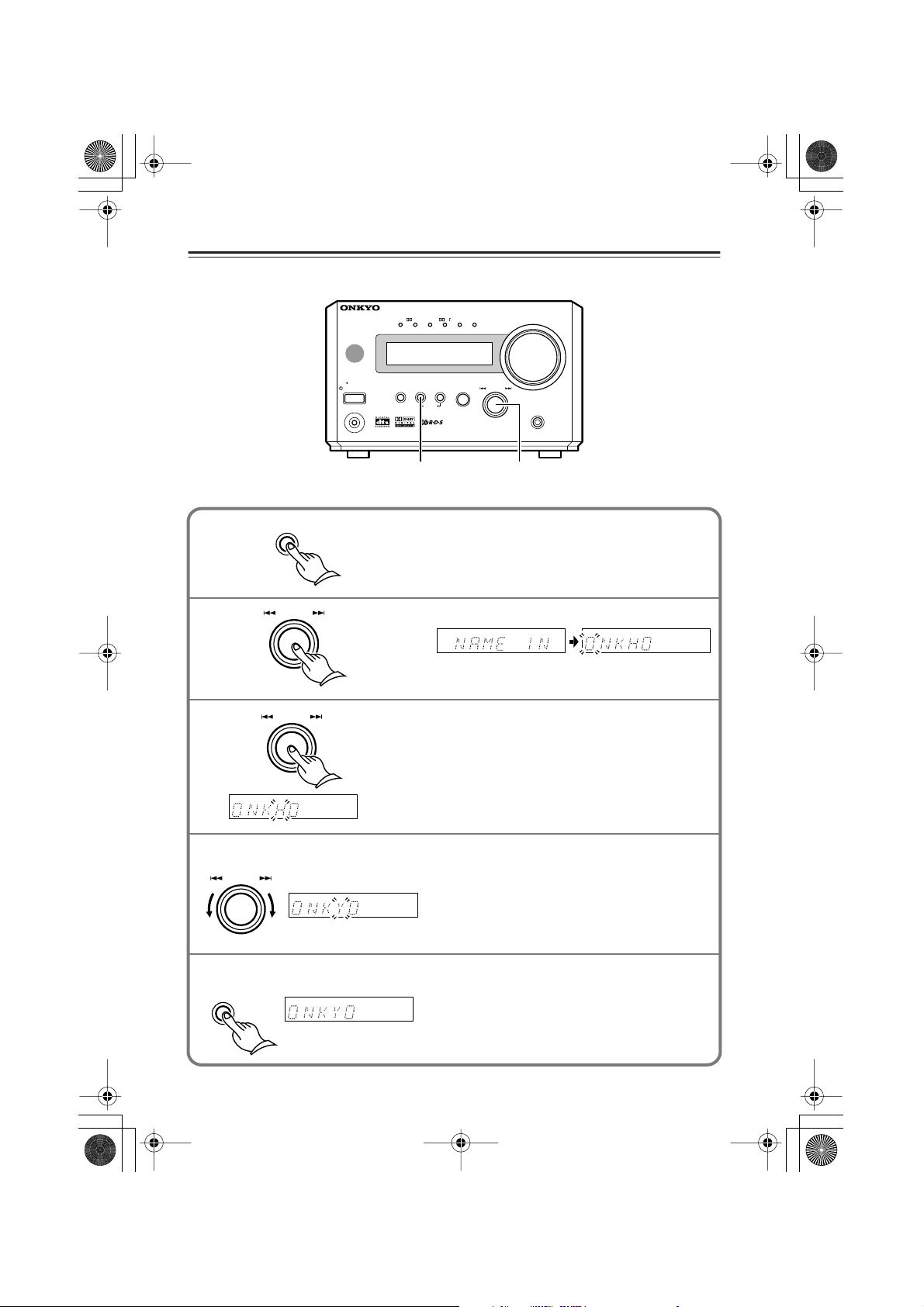
HTC-V10X_En.book Page 60 Wednesday, July 21, 2004 2:49 PM
Entering Characters —Continued
Changing the characters
AV CONTROLLER
DTSPCM DIGITAL DSP STEREO
(
)
GRN
PL
(
)
MULTI IN
RED
■
MASTER VOLUME
STANDBY
STANDBY / ON
PHONES
SW LV L CTRL
1,5 2
MEMORY
CLEAR
INPUT
TIMER
MULTI JOG
PUSH TO ENTER
–
First select the preset station you wish to change a name.
1
2
3
MEMORY
MULTI JOG
PUSH TO ENTER
MULTI JOG
Press and hold down MEMORY to display
“NAME IN.”
Press MULTI JOG.
Select a character to edit.
Press MULTI JOG repeatedly until the character
you wish to change flashes.
PUSH TO ENTER
SURROUND
4
-
PR
155X
60
4
PUSH TO ENTER
5
MEMORY
MULTI JOG
Press MULTI JOG to select a new character.
• After you select a new character, press MULTI
JOG.
• Repeat Steps 3 and 4 if you wish to change
other characters.
Press and hold down MEMORY to store
the change.
Page 61

HTC-V10X_En.book Page 61 Wednesday, July 21, 2004 2:49 PM
Entering Characters —Continued
Deleting the characters
1
2
3
MEMORY
MULTI JOG
PUSH TO ENTER
MULTI JOG
PUSH TO ENTER
Changing the preset indication
MULTI JOG
PUSH TO ENTER
Press and hold down MEMORY to display “NAME IN.”
Rotate MULTI JOG to display “NAME
ERS.”
Press MULTI JOG to delete all characters.
Each press of MULTI JOG toggles between
two types of preset indications as follows:
Preset frequency
RDS:
Preset number or name
(if named)
PSFrequency PT
Tip:
• If a preset station has been named, the name
is displayed as default. If it is not named, the
preset number or frequency is displayed.
61
Page 62

HTC-V10X_En.book Page 62 Wednesday, July 21, 2004 2:49 PM
Setting the Distance to the Speakers
This setting enables you to specify the distance from the
listening position to the speakers.
When this distance is correctly specified, the sound from
each speaker reaches the listening position simultaneously,
improving your home theater experience.
This setting is also memorized in Standby mode.
2
3
1,4
1
2
3
4
Press DISTANCE on the remote controller.
The unit displays the distance from the front
left and right speakers to the listening position.
Press ▲/▼ to specify the real distance.
Press ▲ to increase the value, and press ▼ to
decrease the value. You can specify the distance
up to 9.0 m by 0.3 m steps.
Press CH SEL to select another
speaker, then specify the speaker distance.
Each press of CH SEL switches the speaker
indication as follows. Follow Step 2 to specify
the distance.
FRT (Front speakers)
CNT (Center speaker)
SUR (Surround left and right speakers)
Press DISTANCE.
The specified speaker distances are memorized
and the unit displays the standard screen.
Notes:
• Set the center speaker distance shorter than that of the front left and right speakers and the
surround left and right speakers. The center speaker can be set closer by 1.5 m than the
front left and right speakers.
• The left and right surround speakers can be set closer by 4.5 m than the front left and
right speakers.
•You cannot set the distance while the headphones are connected.
•You cannot set the speaker distance during multi channel audio playback.
62
Page 63

HTC-V10X_En.book Page 63 Wednesday, July 21, 2004 2:49 PM
Balancing the Speaker Volume Levels
Adjust each speaker’s relative volume until each speaker’s
test tone sounds equally loud at the listening position.
• If you switch DVD audio during the speaker level setting, the speaker tone may be muted and the setting
mode may be cancelled.
•You cannot adjust the level while the headphones are
connected.
• This setting is stored after the unit is placed in Standby
mode.
1,4
3
3
MEMORY
2
1
2
3
Center speaker
Press TEST TONE on the remote controller.
Each speaker emits the test tone (pink noise).
L
(Front left )
SW
(Subwoofer)
Adjust the volume level.
Press VOLUME to adjust the level until the test tone is
heard clearly.
• If you do not press any button while the test tone is sounding, each remaining speaker automatically emits the two-second test tone in turn, completing ten rounds through the set
of six speakers. Then the test tone stops.
Volume level
C
(Center)
SL
(Surround left )
/
Press CH SEL repeatedly to
select a speaker, then press ▲/
▼ to adjust the volume level
balance.
Press ▲ to increase the level or press
▼ to lower the level.
•You can adjust the volume level in
the range of –12 dB to +12 dB for
the satellite speakers.
•You can adjust the subwoofer level
in the range of –30 through +12.
R
(Front right )
SR
(Surround right )
4
Note:
• Since the original level of the test tone is soft, if you have raised the volume in Step 2,
press VOLUME after Step 3 to lower the volume to the original level.
/
Press TEST TONE.
The level settings are memorized, and the unit
displays the standard screen.
63
Page 64

HTC-V10X_En.book Page 64 Wednesday, July 21, 2004 2:49 PM
■
Operating the TV from Remote Controller
By programming the TV’s remote control code, you can use the RC-568S remote controller to
operate your TV.
Programming a TV remote control code
1 Find the three-digit number for the
brand name of the component you
want to operate in the table on the
next page.
2 While pressing and holding down
3
2
STANDBY/ON, press ENTER, then
release both buttons.
4
You can use these
buttons to control
your TV.
RC-568S
MEMORY
Release the buttons.
3 Enter the three-digit remote control
code.
Press the number buttons to enter the code
within 30 seconds. This time, you do not
press 10 KEY. Use only the number buttons.
4 Make sure that the remote control
code has been programmed correctly.
Press the remote controller buttons that
control the TV to see if TV responds correctly.
64
Page 65

■
HTC-V10X_En.book Page 65 Wednesday, July 21, 2004 2:49 PM
Operating the TV from Remote Controller —Continued
TV remote control codes
• If more than one code is given in the table, try them one by one until you find the code suitable for your component (i.e. if the first code does not work, try the next one).
Brand Remote control code
AIWA 100, 101
AKAI 102, 103, 104
AUDIOSONIC 105
BELL & HOWELL 106
BLAUPUNKT 107
BRIONVEGA 108, 109
CENTURION 110
COLTINA 111, 112, 113
CORONAD 114
CROWN 115, 116
DAEWOO 117, 118, 119, 120, 121
DUAL 122
EMERSON 123, 124, 125, 126, 127
FENNER 128, 129
FERGUSON 130, 131
FISHER 132
FUNAI 133, 134, 135
FUJITSU GENERAL 136, 137, 138
GE • PANA 139, 140
GE • RCA 141
GOLDSTAR 142, 143
GOODMANS 144
GRUNDIG 145, 146
HITACHI 147, 148, 149, 150
HYPER 151
INNO HIT 152
IRRADIO 103
JVC/VICTOR 153, 154, 155, 156, 157
KENDO 158
KTV 159, 160
LUXOR 161
MAGNAVOX 162, 163
MARANTZ 164
MARK 165
MATSUI 166, 167, 168, 169
MITSUBISHI 170, 171, 172, 173
MIVAR 174, 175
NEC 176, 177
NOKIA 178, 179, 180, 181
OCEANIC 181
NORDMENDE 182, 183
Brand Remote control code
OKANO 152
ORION 184, 185, 186
PANASONIC 187, 188, 189, 190
PHILIPS 152, 162, 191
PIONEER 192, 193
PROSCAN 194
QUASAR 195
RADIO SHACK 196
RCA 110, 141, 197, 198, 199,
200
SABA 182, 183, 201
SAMSUNG 202, 203, 204, 205, 206,
207, 208
SANYO 209, 210, 211, 212
SCHNEIDER 103
SEARS 213
SELECO 214, 215
SHARP 216, 217
SONY 218, 219, 220, 221, 222,
223
SYMPHONIC 224, 225
TELEFUNKEN 201, 226, 227
THOMSON 228
TOSHIBA 213, 229
UNIVERSUM 230
ZENITH 231, 232
Default: 100
65
Page 66

HTC-V10X_En.book Page 66 Wednesday, July 21, 2004 2:49 PM
Troubleshooting
If you have any trouble, consult the following list.
The HTC-V10X is designed to offer the best performance when you use a subwoofer SWA-V10X, and
speakers ST-V10X, and an AV controller PR-155X. Onkyo does not guarantee the performance and is not
responsible for malfunctions caused by using other speakers or amplifiers.
Power Pages
The power to the system is not turned on.
• Make sure that the power cable is plugged into the AC outlet.
• Make sure that the multi-splitter cable is securely connected to the subwoofer and
the SUBWOOFER CONTROL connector on the rear panel of the PR-155X. 19
• Unplug the power cable from the AC outlet, wait for five seconds or more, then plug the cable in again.
The power is turned off during the operation.
• If the TIMER indicator is lit on the display, the timer is functioning. Cancel the timer. 56
• The PR-155X enters Standby mode after the timer playback or recording is complete.
Audio
The sound is not heard.
• Make sure that the subwoofer’s power cable is plugged to the AC outlet.
• Make sure that the multi-splitter cable is connected correctly.
Make sure that you do not mix the SUBWOOFER CONTROL jack on PR-155X’s rear panel
with the jack. 19
• Make sure that the speakers are connected correctly and the speaker cables’ core wires touch
the speaker connectors. 20
• Make sure that the correct input source is selected.
You need to select the connected component as the input source. 32
• Check to see if the volume level is set to minimum.
• Check the digital output setting on the connected component. The default digital output setting on some DVD-compatible game components may be turned off.
• The speakers do not output sound if the headphones are connected. 34
• The optical cable may be bent or damaged.
• Check to see if the muting function is working.
If the MUTING indicator is flashing, the sound is muted. Cancel the muting function. 34
• Check the output setting on the connected playback component.
• Make sure that the component is connected via the correct input jacks. 22–25
• Make sure that the input setting on the connected component is correct.
Sound from the connected turntable is very soft.
• Check to see if the turntable has an internal phono equalizer. If it does not have a phono equalizer, obtain an optional
one.
Playing a record on the turntable does not produce sound.
• If you are using a turntable with an MC cartridge, you will need a transformer or head amplifier to boost the voltage, and
a phono equalizer.
About DTS signals
• If you play a CD or LD that features DTS signals through the analog connectors, the DTS signals will be played without
any conversion, resulting in noise. This noise could damage the unit and/or speakers. Be sure to play any such CD or LD
through the DIGITAL INPUT connector.
• Some CDs or LDs may not play DTS signals correctly even through the digital connection. If the DTS data on such
discs have been processed (e.g., output level adjustment, sampling frequency conversion, frequency response conversion, etc.), the unit may be unable to interpret such data as standard DTS data, and may output noise as a result.
• While you are playing a disc that features DTS signals, if you pause or skip tracks on the CD or LD player, noise may be
generated for a short period of time. This is not a malfunction.
66
Page 67
HTC-V10X_En.book Page 67 Wednesday, July 21, 2004 2:49 PM
Troubleshooting —Continued
About tonal quality
Sound may improve if you switch the polarity of the power cable plug.
Tonal quality will improve and become stable about 10–30 minutes after you plug in the unit.
Tonal quality may be damaged if you bundle the multi-splitter cable along with the speaker cables.
Home theater
Sound is not good.
• Make sure that the speaker cables are connected correctly. Check their polarity (+/–). 20
• Set each speaker’s distance and volume level. 62
• Connect the audio connection cables firmly.
No sound is output from the center speaker, surround speakers, or subwoofer.
• In some surround modes, sound is not output from these speakers.
STEREO: Sound is output only from the front speakers and subwoofer.
No sound is output from the center speaker and surround speakers.
HALL: No sound is output from the center speaker.
• Sound may not be heard clearly when certain sources play in DOLBY PRO LOGIC II surround mode.
Signals or sound effects to create realistic scenes are sometimes included on the DVDs and BS digital broadcasts that
support 5.1ch. However, they are not included in CDs and standard broadcasts. Select another surround mode.
• Make sure that the speakers are connected correctly and the speaker cables’ core wires touch
the speaker connectors. 20
• No sound will be output from the subwoofer if you are playing a disc that does not feature a subwoofer audio range
(LFE).
• Adjust the subwoofer level. 40
• When monaural audio from TV or AM radio stations is being played, the sound will be output mostly from the center
speaker if the Surround mode is set to PL II Movie or PL II Music. If this sounds awkward, change the Surround mode.
Surround effects do not work.
•You cannot change the Surround mode during multi channel audio playback.
The Late Night function does not work. (The unit displays “CAN NOT.”)
• Make sure that the source features Dolby Digital.
Multi channel audio is not output.
• Make sure that you are using a DVD player that is compatible with multi channel audio.
• Select “DVD M. In” for the input source. Also, select “Multi” using the MODE button on the remote controller.
•You can select “DVD M. In” and “Multi” only when the input source is a DVD.
Radio
Noise is heard during broadcast, or too much white noise is heard during an FM stereo broadcast.
You cannot tune in the broadcast station using the Auto Preset function (for only FM stations).
Or, the ST indicator does not light up during FM broadcast.
• Change the location of the antenna.
• Locate the unit further from the TV or a computer. 7
• Cars or airplanes can create noisy interference.
•A broadcast radio signal may be weak if a concrete wall obstructs the signal path.
•Try setting FM mode to “Mono.” 42
• Noise may be heard when you operate the remote controller during AM reception.
• If nothing can improve the reception, install an outdoor antenna. 28
Remote controller
The remote controller does not function correctly. Or, the TV does not respond to the remote controller operation.
• Make sure that the batteries have been installed in the correct direction (polarity +/–). 11
67
Page 68

HTC-V10X_En.book Page 68 Wednesday, July 21, 2004 2:49 PM
Troubleshooting —Continued
• Replace both batteries with new ones.
(Do not mix different types of batteries or new and old batteries.) 11
• The distance between the remote controller and the unit may be too far.
Or, there may be an object between them. 11
• The remote control sensor on the unit may be receiving a strong beam of light
(inverter fluorescent light or sunlight). 11
• The unit is placed behind the tinted windows of the audio rack or entertainment center. 11
• Make sure that the TV code has been programmed in the remote controller correctly.
Find the TV’s remote control code in the remote control list and reprogram it. 64
• If you have connected an external component, set the input indication correctly. 32
System connection with other components
You cannot record.
•To perform digital recording, connect the digital output of the playing component to the digital input of the recording
component.
• Make sure that all system components are connected correctly.
• Make sure that the input source setting (analog or digital) on the recording player is correct.
• Make sure that the system is connected correctly. 19–25
The system functions do not work.
• Make sure that the cable and audio connection cables are connected correctly.
(Connecting only the cable does not complete the system connection.) 27
• Switch the input source indication correctly. 32
Timer playback or recording does not work.
• The clock should be set correctly.
If the clock is not set, timer playback or recording does not work. Make sure you program the current time.
• When the power is turned on, make sure that the unit displays “TIMER.”
• Make sure that the cable and audio connection cables are connected correctly. 27
• Check the settings of the playback and recording components. (You cannot perform timer recording with a CD
recorder.)
52
Others
The colors of the TV picture bleed.
• Locate the speakers far from the TV.
You are unable to set the correct speaker distance.
• The distance value may be corrected to a value suitable for the home theater environment.
The maximum volume available does not exceed 96 (or does exceed 97).
• After you adjust the balance speaker volume levels, the maximum volume setting may change.
This product uses a micro computer to perform various advanced functions. However, noise, radio interference, or static electricity could occasionally cause the unit to malfunction. In this case, unplug the power
cable from the AC outlet, then plug it in again in five seconds.
Onkyo is not responsible for damages (such as CD rental fees) due to unsuccessful recordings caused by the
unit’s malfunction. Before you record important data, make sure that the material will be recorded correctly.
Restoring the factory default settings:
To reset all the stored settings to the factory default conditions, while the power to the PR-155X is on, press
and hold down the INPUT on the unit, and press STANDBY/ON. The unit displays “CLEAR,” and restores the
factory default settings, then enters Standby mode.
68
Page 69

HTC-V10X_En.book Page 69 Wednesday, July 21, 2004 2:49 PM
Specifications
PR-155X
Input Sensitivity and Impedance 150 mV / 50 k Ω (LINE)
Output Level and Impeadance 1 V / 600 Ω (STEREO ,VOLUME MAX at max.)
Frequency Response 120 Hz–20 kHz : +1 / –3 dB (FL/FR/C/SL/SR)
20 Hz–120 Hz : 0 / –3 dB (SW)
Tuner Section
Tuning Frequency Range FM 87.50–108.00 MHz, AM 522–1611 kHz
Frequency Response 30 Hz–15 kHz (±1.5dB)
General
Power Comsumption 15 W
Dimensions(W x H x D) 155 x 94 x 288 mm
Weight 2.0 kg
•Audio inputs
Digital Inputs 3 (OPTICAL) (DVD/CD, CDR/TAPE/TV/VIDEO, LINE/
GAME)
Analog Inputs 2 (MD, CDR/TAPE/TV/VIDEO)
Multichannel Inputs 1 (FL, FR, C, SL, SR, SW) FL/FR input jacks are com-
mon to DVD/CD L and R
■
•Audio outputs
Analog Outputs 2 (MD, CDR/TAPE/TV/VIDEO)
Pre Outputs FL, FR, C, SL, SR, SW
Phones 1
69
Page 70

■
HTC-V10X_En.book Page 70 Wednesday, July 21, 2004 2:49 PM
Specifications —Continued
SWA-V10X
Type Bass-reflex (Slit-duct Aero Acoustic Technology)
Input Sensitivity and Impedance 500 mV / 47 k Ω (FL/FR/C/SL/SR/SW)
Maximum output power Front 15 W x 2 (6 Ω /JEITA)
11 W x 2 (6 Ω /DIN)
Center 15 W (6 Ω /JEITA)
11 W (6 Ω /DIN)
Surround 15 W x 2 (6 Ω /JEITA)
11 W x 2 (6 Ω /DIN)
Subwoofer 25 W (3 Ω /JEITA)
20 W (3 Ω /DIN)
Frequency Response 30 Hz–150 Hz
Signal to noise ratio 100 dB (STEREO IHF-A)
Cabinet capacity 9.3 litter
Dimensions(W x H x D) 190 x 313 x 353 mm (include grille, jacks)
Weight 8.7 kg
Inputs 1 (FL, FR, C, SL, SR, SW)
Speaker 16cm OMF Cone
Power supply 230–240V to 50Hz
Power consumption 65 W
Other Magnetic shielding
■
ST-V10X
Type Full range enclosed
Frequency Response 6 Ω
Maximum input power 30 W
Output sound pressure level 83 dB/W/m
Frequency Response 125 Hz–15 kHz
Cabinet capacity 0.6 litter
Dimensions(W x H x D) 85 x 120 x 112 mm (include grille, jacks)
Weight 0.7 kg
Speaker 8 cm OMF cone, full range
Other Magnetic shielding
Specifications and features are subject to change without notice.
70
Page 71

HTC-V10X_En.book Page 71 Wednesday, July 21, 2004 2:49 PM
Memo
71
Page 72

HTC-V10X_En.book Page 72 Wednesday, July 21, 2004 2:49 PM
Sales & Product Planning Div. : 2-1, Nisshin-cho, Neyagawa-shi, OSAKA 572-8540, JAPAN
Tel: 072-831-8023 Fax: 072-831-8124
ONKYO U.S.A. CORPORATION
18 Park Way, Upper Saddle River, N.J. 07458, U.S.A.
Tel: 201-785-2600 Fax: 201-785-2650 http://www.onkyousa.com
ONKYO EUROPE ELECTRONICS GmbH
Liegnitzerstrasse 6, 82194 Groebenzell, GERMANY
Tel: +49-8142-4401-0 Fax: +49-8142-4401-555 http://www.onkyo.net
ONKYO EUROPE UK Office
Suite 1, Gregories Court, Gregories Road, Beaconsfield, Buckinghamshire, HP9 1HQ
UNITED KINGDOM Tel: +44-(0)1494-681515 Fax: +44(0)-1494-680452
ONKYO CHINA LIMITED
Units 2102-2107, Metroplaza Tower I, 223 Hing Fong Road, Kwai Chung,
N.T., HONG KONG Tel: 852-2429-3118 Fax: 852-2428-9039
SN 29343859
(C) Copyright 2004 ONKYO CORPORATION Japan. All rights reserved.
72
* 2 9 3 4 3 8 5 9 *
http://www.onkyo.com/
HOMEPAGE
Printed in Japan
I0407-1
 Loading...