

Page 1

DVD Receiver
DR-S2.2
Instruction Manual
Contents
Before Using Your DVD Receiver 2
Getting Started
Thank you for purchasing the Onkyo DVD Receiver.
Please read this manual thoroughly before making
connections and turning on the power.
Following the instructions in this manual will enable
you to obtain optimum performance and listening
enjoyment from your new DVD Receiver.
Please retain this manual for future reference.
Setup
Basic Operation
Advanced Operation
Other
Page 2
WARNING:
TO REDUCE THE RISK OF FIRE OR ELECTRIC SHOCK,
DO NOT EXPOSE THIS APPLIANCE TO RAIN OR
MOISTURE.
CAUTION:
TO REDUCE THE RISK OF ELECTRIC SHOCK, DO NOT
REMOVE COVER (OR BACK). NO USER-SERVICEABLE
PARTS INSIDE. REFER SERVICING TO QUALIFIED
SERVICE PERSONNEL.
Important Safeguards
WARNING
RISK OF ELECTRIC SHOCK
DO NOT OPEN
The lightning flash with arrowhead symbol, within an equilateral
triangle, is intended to alert the user to the presence of uninsulated
“dangerous voltage” within the product’s enclosure that may be of
sufficient magnitude to constitute a risk of electric shock to persons.
The exclamation point within an equilateral triangle is intended to alert
the user to the presence of important operating and maintenance
(servicing) instructions in the literature accompanying the appliance.
AVIS
RISQUE DE CHOC ELECTRIQUE
OUVRIR
NE PAS
1. Read Instructions – All the safety and operating instructions
should be read before the appliance is operated.
2. Retain Instructions – The safety and operating instructions
should be retained for future reference.
3. Heed Warnings – All warnings on the appliance and in the
operating instructions should be adhered to.
4. Follow Instructions – All operating and use instructions should
be followed.
5. Cleaning – Unplug the appliance from the wall outlet (the
mains) before cleaning. The appliance should be cleaned only
as recommended by the manufacturer.
6. Attachments – Do not use attachments not recommended by
the appliance manufacturer as they may cause hazards.
7. Water and Moisture – Do not use the appliance near water –for
example, near a bath tub, wash bowl, kitchen sink, or laundry
tub; in a wet basement; or near a swimming pool; and the like.
8. Accessories – Do not place the appliance on an unstable cart,
stand, tripod, bracket, or table. The appliance may fall, causing
serious injury to a child or adult, and serious damage to the
appliance. Use only with a cart, stand, tripod, bracket, or table
recommended by the manufacturer, or sold with the appliance.
Any mounting of the appliance should follow the manufacturer’s
instructions, and should use a mounting accessory
recommended by the manufacturer.
9. An appliance and cart combination should
be moved with care. Quick stops,
excessive force, and uneven surfaces
may cause the appliance and cart
combination to overturn.
10. Ventilation – Slots and openings in the cabinet are provided for
ventilation and to ensure reliable operation of the appliance and
to protect it from overheating, and these openings must not be
blocked or covered. The openings should never be blocked by
placing the appliance on a bed, sofa, rug, or other similar
surface. The appliance should not be placed in a built-in
installation such as a bookcase or rack unless proper ventilation
is provided. There should be free space of at least 20 cm (8 in.)
and an opening behind the appliance.
11. Power Sources – The appliance should be operated only from
the type of power source indicated on the marking label. If you
are not sure of the type of power supply to your home, consult
your appliance dealer or local power company.
12. Grounding or Polarization – The appliance may be equipped
with a polarized alternating current line plug (a plug having one
blade wider than the other). This plug will fit into the power
outlet only one way. This is a safety feature. If you are unable to
insert the plug fully into the outlet, try reversing the plug. If the
plug should still fail to fit, contact your electrician to replace your
obsolete outlet. Do not defeat the safety purpose of the
polarized plug.
PORTABLE CART WARNING
S3125A
13. Power-Cord Protection – Power-supply cords (mains leads)
should be routed so that they are not likely to be walked on or
pinched by items placed upon or against them, paying particular
attention to cords (leads) at plugs, convenience receptacles, and
the point where they exit from the appliance.
14. Outdoor Antenna (Aerial) Grounding – If an outside antenna (aerial)
or cable system is connected to the appliance, be sure the antenna
(aerial) or cable system is grounded so as to provide some protection
against voltage surges and built-up static charges. Article 810 of the
National Electrical Code, ANSI/NFPA 70, provides information with
regard to proper grounding of the mast and supporting structure,
grounding of the lead-in wire to an antenna- (aerial-) discharge unit,
size of grounding conductors, location of antenna- (aerial-) discharge
unit, connection to grounding electrodes, and requirements for the
grounding electrode. See FIGURE 1.
15. Lightning – For added protection for the appliance during a
lightning storm, or when it is left unattended and unused for long
periods of time, unplug it from the wall outlet (the mains) and
disconnect the antenna (aerial) or cable system. This will prevent
damage to the appliance due to lightning and power-line surges.
16. Power Lines – An outside antenna (aerial) system should not be
located in the vicinity of overhead power lines or other electric light or
power circuits, or where it can fall into such power lines or circuits.
When installing an outside antenna (aerial) system, extreme care
should be taken to keep from touching such power lines or circuits as
contact with them might be fatal.
17. Overloading – Do not overload wall outlets, extension cords
(leads), or integral convenience receptacles as this can result in a
risk of fire or electric shock.
18. Object and Liquid Entry – Never push objects of any kind into the
appliance through openings as they may touch dangerous voltage
points or short-out parts that could result in a fire or electric shock.
Never spill liquid of any kind on the appliance.
19. Servicing – Do not attempt to service the appliance yourself as
opening or removing covers may expose you to dangerous voltage
or other hazards. Refer all servicing to qualified service personnel.
20. Damage Requiring Service – Unplug the appliance form the wall
outlet (the mains) and refer servicing to qualified service personnel
under the following conditions:
A. When the power-supply cord (mains lead) or plug is damaged,
B. If liquid has been spilled, or objects have fallen into the
appliance,
C. If the appliance has been exposed to rain or water,
D. If the appliance does not operate normally by following the
operating instructions. Adjust only those controls that are
covered by the operating instructions as an improper
adjustment of other controls may result in damage and will
often require extensive work by a qualified technician to restore
the appliance to its normal operation,
E. If the appliance has been dropped or damaged in any way, and
F. When the appliance exhibits a distinct change in performance –
this indicates a need for service.
2
Page 3
21. Replacement Parts – When replacement parts are required, be
sure the service technician has used replacement parts
specified by the manufacturer or have the same characteristics
as the original part. Unauthorized substitutions may result in
fire, electric shock, or other hazards.
22. Safety Check – Upon completion of any service or repairs to
the appliance, ask the service technician to perform safety
checks to determine that the appliance is in proper operation
condition.
23. Wall or Ceiling Mounting – The appliance should be mounted
to a wall or ceiling only as recommended by the manufacturer.
24. Heat – The appliance should be situated away from heat
sources such as radiators, heat registers, stoves, or other
appliances (including amplifiers) that produce heat.
25. Liquid Hazards – The appliance shall not be exposed to
dripping or splashing and no objects filled with liquids, such as
vases shall be placed on the appliance.
Precautions
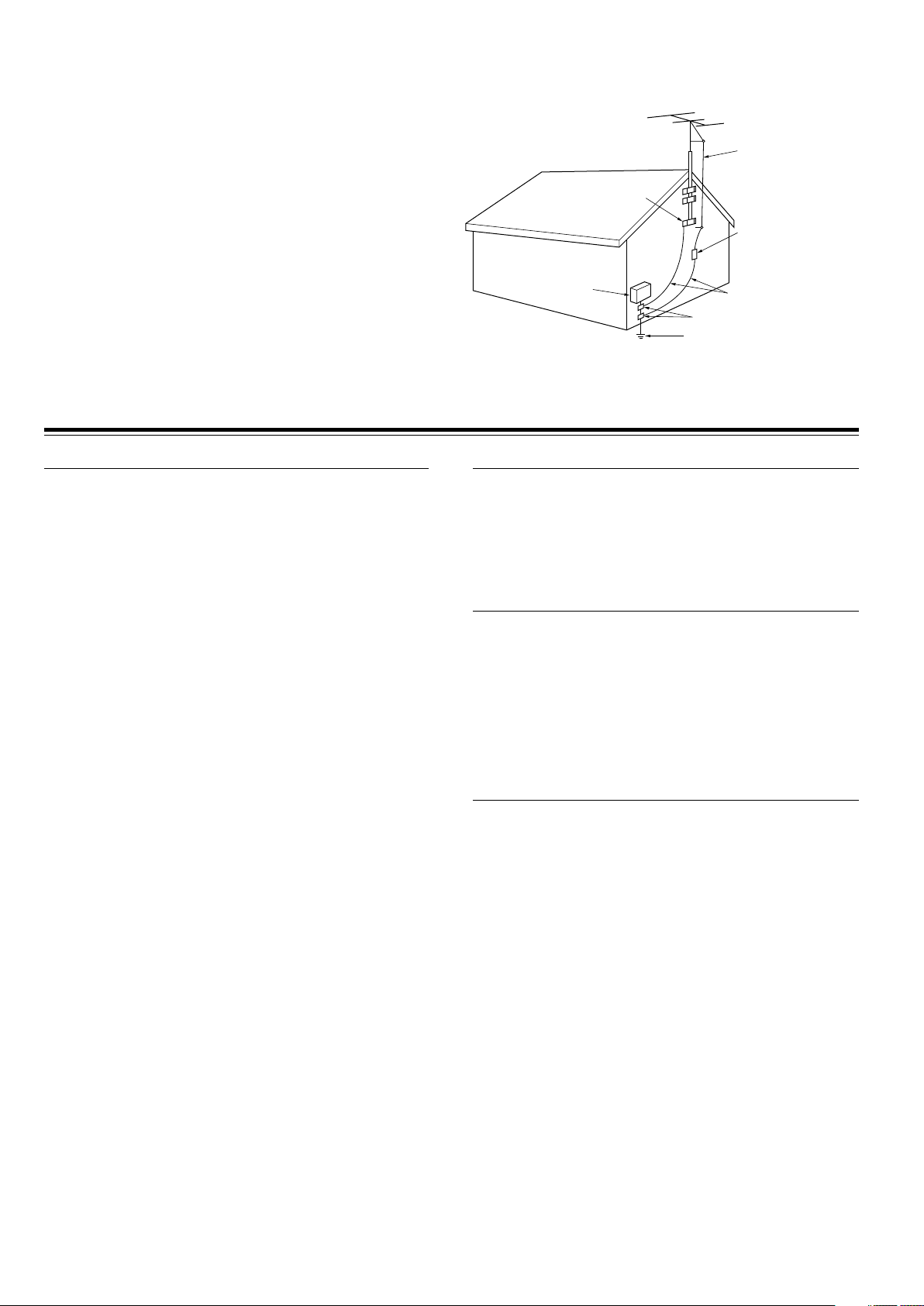
FIGURE 1:
EXAMPLE OF ANTENNA (AERIAL) GROUNDING AS PER NATIONAL
ELECTRICAL CODE, ANSI/NFPA 70
ANTENNA
LEAD IN
WIRE
GROUND
CLAMP
ANTENNA
DISCHARGE UNIT
(NEC SECTION 810-20)
ELECTRIC
SERVICE
EQUIPMENT
NEC – NATIONAL ELECTRICAL CODE
S2898A
GROUNDING CONDUCTORS
(NEC SECTION 810-21)
GROUND CLAMPS
POWER SERVICE GROUNDING
ELECTRODE SYSTEM
(NEC ART 250, PART H)
For U.S. model
The laser is covered by a housing which prevents exposure during
operation or maintenance. However, this product is classified as a
Laser Product by CDRH (Center for Devices and Radiological
Health) which is a department of the Food and Drug Administration.
According to their regulations 21 CFR section 1002.30, all
manufactures who sell Laser Products must maintain records of
written communications between the manufacturer, dealers and
customers concerning radiation safety. If you have any complaints
about instructions or explanations affecting the use of this product,
please feel free to write to the address on the back page of this
manual. When you write us, please include the model number and
serial number of your unit.
In compliance with Federal Regulations, the certification,
identification and the period of manufacture are indicated on the rear
panel.
FCC INFORMATION FOR USER
CAUTION:
The user changes or modifications not expressly approved by the
party responsible for compliance could void the user’s authority to
operate the equipment.
NOTE:
This equipment has been tested and found to comply with the limits
for a Class B digital device, pursuant to Part 15 of the FCC Rules.
These limits are designed to provide reasonable protection against
harmful interference in a residential installation. This equipment
generates, uses and can radiate radio frequency energy and, if not
installed and used in accordance with the instructions, may cause
harmful interference to radio communications. However, there is no
guarantee that interference will not occur in a particular installation.
If this equipment does cause harmful interference to radio or
television reception, which can be determined by turning the
equipment off and on, the user is encouraged to try to correct the
interference by one or more of the following measures:
• Reorient or relocate the receiving antenna.
• Increase the separation between the equipment and receiver.
• Connect the equipment into an outlet on a circuit different from
that to which the receiver is connected.
• Consult the dealer or an experienced radio/TV technician for help.
Note to CATV system installer:
This reminder is provided to call the CATV system installer’s
attention to Article 820-40 of the NEC, ANSI/NFPA 70, which
provides guidelines for proper grounding and, in particular, specifies
that the cable ground shall be connected to the grounding system of
the building, as close to the point of cable entry as practical.
For Canadian model
This class B digital apparatus complies with Canadian ICES-003.
For models having a power cord with a polarized plug:
CAUTION: TO PREVENT ELECTRIC SHOCK, MATCH WIDE
BLADE OF PLUG TO WIDE SLOT, FULLY INSERT.
Modèle pour les Canadien
Cet appareil numérique de la classe B est conforme à la norme
NMB-003 du Canada.
Sur les modèles dont la fiche est polarisée:
ATTENTION: POUR ÈVITER LES CHOCS ÉLECTRIQUES,
INTRODUIRE LA LAME LA PLUS LARGE DE LA FICHE DANS LA
BORNE CORRESPONDANTE DE LA PRISE ET POUSSER
JUSQU’AU FOND.
For British model
Replacement and mounting of an AC plug on the power supply cord
of this unit should be performed only by qualified service personnel.
IMPORTANT
The wires in the mains lead are coloured in accordance with the
following code:
Blue: Neutral
Brown: Live
As the colours of the wires in the mains lead of this apparatus may
not correspond with the coloured markings identifying the terminals
in your plug, proceed as follows:
The wire which is coloured blue must be connected to the terminal
which is marked with the letter N or coloured black.
The wire which is coloured brown must be connected to the terminal
which is marked with the letter L or coloured red.
IMPORTANT
A 5 ampere fuse is fitted in this plug. Should the fuse need to be
replaced, please ensure that the replacement fuse has a rating of 5
amperes and that it is approved by ASTA or BSI to BS1362. Check
for the ASTA mark or the BSI mark on the body of the fuse.
IF THE FITTED MOULDED PLUG IS UNSUITABLE FOR THE
SOCKET OUTLET IN YOUR HOME THEN THE FUSE SHOULD BE
REMOVED AND THE PLUG CUT OFF AND DISPOSED OF
SAFELY. THERE IS A DANGER OF SEVERE ELECTRICAL
SHOCK IF THE CUT OFF PLUG IS INSERTED INTO ANY 13
AMPERE SOCKET.
If in any doubt, please consult a qualified electrician.
3
Page 4
Precautions
CAUTION:
VISIBLE LASER RADIATION WHEN OPEN AND INTERLOCK
FAILED OR DEFEATED. DO NOT STARE INTO BEAM.
CAUTION:
THIS PRODUCT UTILIZES A LASER. USE OF CONTROLS OR
ADJUSTMENTS OR PERFORMANCE OF PROCEDURES
OTHER THAN THOSE SPECIFIED HEREIN MAY RESULT IN
HAZARDOUS RADIATION EXPOSURE.
This unit contains a semiconductor laser system and is classified
as a “CLASS 1 LASER PRODUCT.” So, to use this model properly,
read this Instruction Manual carefully. In case of any trouble,
please contact the store where you purchased the unit. To prevent
being exposed to the laser beam, do not try to open the enclosure.
For European model
“CLASS 1 LASER
PRODUCT ”
This label on the rear panel states that:
1. This unit is a CLASS 1 LASER PRODUCT and employs a
laser inside the cabinet.
2. To prevent the laser from being exposed, do not remove the
cover. Refer servicing to qualified personnel.
1. Regional Restriction Codes (Region Number)
Regional restriction codes are built into DVD Receivers and DVD
videos for each sales region. If the regional code of the DVD
Receiver does not match one of the regional codes on the DVD
video, playback is not possible.
The regional number can be found on the rear panel of the DVD
Receiver. (e.g. 1 for Region 1)
2. About This Manual
This manual explains the basic procedures for operating the DVD
Receiver. Some DVD videos do not support the full potential of the
DVD technology. Your DVD Receiver may therefore not respond
to all operating commands. Refer to instruction notes on discs.
A “ ” mark may appear on the TV screen during operation. It
means that the operation is not permitted by the DVD Receiver or
the disc.
3. Recording Copyright
Recording of copyrighted material for other than personal use is
illegal without permission of the copyright holder.
4. AC Fuse
The fuse is located inside the chassis and is not user-serviceable.
If power does not come on, contact your Onkyo authorized service
center.
5. Power
WARNING
BEFORE PLUGGING IN THE UNIT FOR THE FIRST TIME, READ
THE FOLLOWING SECTION CAREFULLY.
The voltage of the available power supply differs according to
country or region. Be sure that the power supply voltage of the
area where the unit will be used meets the required voltage (AC
120V 60Hz or AC 230-240V 50Hz) written on the rear panel.
6. Do not touch the unit with wet hands
Do not handle the unit or power cord (mains lead) when your hands
are wet or damp. If water or any other liquid enters the case, take
the unit to an authorized service center for inspection.
4
7. Location of the unit
• Place the unit in a well-ventilated location.
Take special care to provide plenty of ventilation on all sides of
the unit especially when it is placed in an audio rack. If ventilation
is blocked, the unit may overheat and malfunction.
• Do not expose the unit to direct sunlight or heating units as the
unit's internal temperature may rise and shorten the life of the
pickup.
• Avoid damp and dusty places and places directly affected by
vibrations from the speakers. In particular, avoid placing the unit
on or above one of the speakers.
• Be sure the unit is placed in a horizontal position. Never place it
on its side or on a slanted surface as it may malfunction.
• When you place the unit near a TV, radio, or VCR, the playback
picture may become poor and the sound may be distorted. In
this case, place the unit away from the TV, radio, or VCR.
8. Care
From time to time you should wipe the front and rear panels and
the cabinet with a soft cloth. For heavier dirt, dampen a soft cloth
in a weak solution of mild detergent and water, wring it out dry, and
wipe off the dirt. Following this, dry immediately with a clean cloth.
Do not use rough material, thinners, alcohol or other chemical
solvents or cloths since these could damage the finish or remove
the panel lettering.
9. Notes on Handling
• When shipping the unit, use the original shipping carton and
packing materials. For maximum protection, repack the unit as
it was originally packed at the factory.
• Do not use volatile liquids, such as insect spray, near the unit.
Do not leave rubber or plastic products in contact with the unit
for a long time. They will leave marks on the finish.
• The top and rear panels of the unit may become warm after a
long period of use. This is not a malfunction.
• When the unit is not in use, be sure to remove the disc and turn
off the power.
• If you do not use the unit for a long period, the unit may not
function properly in the future. Turn on and use the unit
occasionally.
10. To Obtain a Clear Picture
The unit is a high technology, precision device. If the optical pickup lens and disc drive parts are dirty or worn down, the picture
quality becomes poor. To obtain a clear picture, we recommend
regular inspection and maintenance (cleaning or parts
replacement) every 1,000 hours of use depending on the operating
environment. For details, contact your nearest dealer.
11. Notes on Moisture Condensation
Moisture condensation damages the unit.
Please read the following carefully.
• What is moisture condensation?
Moisture condensation occurs, for example, when you pour a
cold drink into a glass on a warm day. Drops of water form on
the outside of the glass. In the same way, moisture may condense
on the optical pick-up lens inside the unit, one of the most crucial
internal parts of the unit.
• Moisture condensation occurs in the following cases.
– When you bring the unit directly from a cold place to a warm
place.
– When you use the unit in a room where you just turned on the
heater, or a place where the cold wind from the air conditioner
directly hits the unit.
– In summer, when you use the unit in a hot and humid place
just after you move the unit from an air conditioned room.
– When you use the unit in a humid place.
• Do not use the unit when moisture condensation may occur.
If you use the unit in such a situation, it may damage discs and
internal parts. Remove the disc, connect the power cord (mains
lead) of the unit to the wall outlet (the mains), turn on the unit,
and leave it for two or three hours. After a few hours, the unit will
have warmed up and evaporated any moisture. Keep the unit
connected to the wall outlet (the mains) and moisture
condensation will seldom occur.
Page 5

Table of Contents
Important Safeguards/Precautions/Table of Contents .................................... 2/3/5
Getting Started
Features ................................................................................................................ 6
Supplied Accessories ............................................................................................ 7
Notes on Discs ...................................................................................................... 8
Index to Parts and Controls ................................................................................ 10
Preparing the Remote Controller ........................................................................ 15
Connecting to a TV (Other than European model).............................................. 16
Connecting to a TV (European model)................................................................ 17
Connecting Speakers (North American and South American model) ................. 18
Connecting Speakers (Other models)................................................................. 19
Positioning Speakers .......................................................................................... 20
Connecting to Audio/Video Equipment................................................................ 21
z Connection for the Onkyo MD Recorder or Cassette Tape Deck .................. 23
Making Antenna (Aerial) Connections................................................................. 24
Setup
Connecting the Power/Turning on the DVD Receiver......................................... 26
Setting Up the DVD Receiver ............................................................................. 27
Speaker Setup .................................................................................................... 29
Basic Operation
Getting Started Using Your DVD Receiver .......................................................... 34
Listening to the Radio ......................................................................................... 38
Playing the Connected Source ........................................................................... 40
Various Functions Common to all the Sources ................................................... 42
Enjoying the Sound Effects ................................................................................. 44
Advanced Operation
Still Frame/Slow Play .......................................................................................... 51
Locating a Specific Title/Folder/Chapter/Track/Location ..................................... 52
Repeat Play ........................................................................................................ 54
Random Play ...................................................................................................... 55
Playing in a Favourite Order ............................................................................... 56
Selecting the Camera Angle ............................................................................... 60
Selecting the Audio/Subtitle Language ............................................................... 61
Viewing Disc Information..................................................................................... 62
Customizing the Function Settings ..................................................................... 64
Recording Using the Connected Equipment ....................................................... 77
Controlling other components connected to the DVD Receiver.......................... 78
Other
Troubleshooting .................................................................................................. 84
Specifications ...................................................................................................... 87
5
Page 6
Features
Receiver Features
40 watts per channel into 6 ohms (FTC)
35 watts per channel into 6 ohms (DIN)
45 watts per channel into 6 ohms (EIAJ)
96 kHz/24-Bit DAC System
DTS* & Dolby** Digital Decoders
Acoustic Control
2 Digital Inputs/1 Output
Subwoofer Preout
4 Audio Inputs/2 Outputs
2 S-Video Inputs/2 Outputs
Theater-Dimensional***
30 FM/AM Random Presets
IPM (Intelligent Power Management)
DVD/CD Player Features
DTS, Dolby Digital, and PCM Compatible
Component-Video Output (Other than European model)
SCART connector (European model)
Progressive Scan (North American model)
27 MHz/10-Bit Video DAC
Plays DVDs, MP3 CDs, CD-Rs, CD-RWs, Video CDs and
Audio CDs
High-Resolution On-screen Display
Program Memory Playback
Auto Last Play
Dual-Wavelength Optical Pickup
Sand-Blasted Aluminum Front Panel
* Manufactured under license from Digital Theater
Systems, Inc. US Pat. No.5,451,942 and other worldwide
patents issues and pending, “DTS” and “DTS Digital
Surround” are trademarks of Digital Theater Systems,
Inc. ©1996 Digital Theater Systems, Inc. All Rights
reserved.
** Manufactured under license from Dolby Laboratories.
“Dolby”, “Pro Logic” and the double-D symbol are
trademarks of Dolby Laboratories. Confidential
Unpublished Works. ©1992-1997 Dolby Laboratories.
All rights reserved.
*** “Theater-Dimensional” and are trademarks of
Onkyo Corporation.
Other Features
Full Function z-compatible Remote Control
Preprogrammed Learning Remote Control
Memory Preservation
This unit does not require memory preservation batteries.
A built-in memory power backup system preserves the
contents of memory during power failures and even when
the POWER switch is set to OFF (European and some
Asian models) or when the power cord is unplugged.
The power cord must be plugged and the POWER switch
must be set to ON (European and some Asian models) in
order to charge the backups system. The memory
preservation period after the unit has been turned off
varies depending on climate and placement of the unit.
On average, memory contents are protected over a
period of a few weeks after the time the unit has been
turned off. This period is shorter when the unit is exposed
to a very humid climate.
Declaration of Conformity
We,
ONKYO EUROPE
ELECTRONICS GmbH
INDUSTRIESTRASSE 20
82110 GERMERING,
GERMANY
declare in own responsibility, that the ONKYO product described
in this instruction manual is in compliance with the corresponding
technical standards such as EN60065, EN55013, EN55020 and
EN61000-3-2, -3-3.
GERMERING, GERMANY
I. MORI
ONKYO EUROPE ELECTRONICS GmbH
6
Page 7
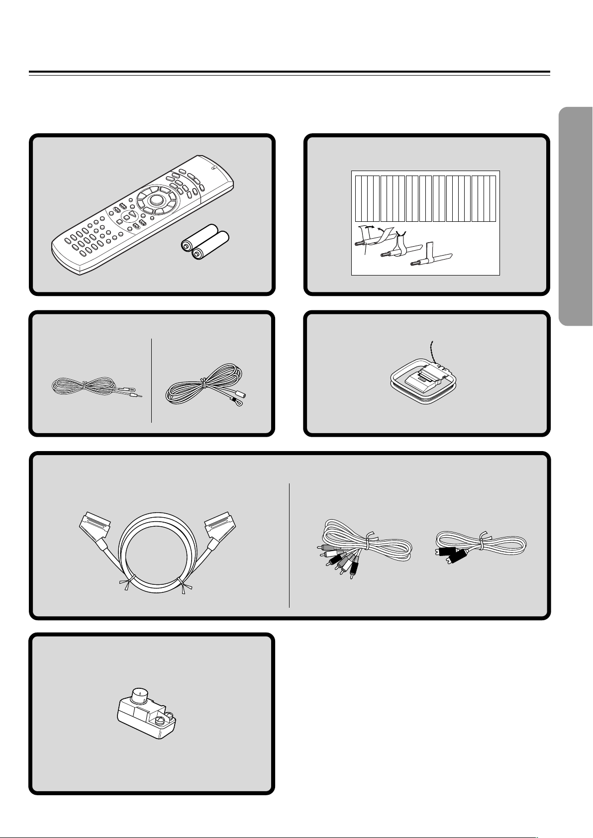
Supplied Accessories
Make sure your box contains everything listed below.
If any pieces are missing, contact your nearest Onkyo service station.
The number of accessories is indicated in brackets.
Remote controller (RC-484M) [1]
Batteries (size AA/R6/UM3) [2]
FM antenna (aerial) [1]
(North American and South
American models)
(Other models)
Speaker Label [1]
Left
Left
Front
Front
Left
Speaker Cable
Left
Left
Front
Zone 2
Zone 2
/
/
SP-B
SP-B
Zone 2
Zone 2
/
/
Front
Left
SP-B
Left
SP-B
Left
1
Left
Left
Front
Front
Right
Right
Front
Right
Front
Right
Zone 2
/
SP-B
Zone 2
/
SP-B
Right
Right
Right
Zone 2
/
Surround
Surround
Surround
SP-B
Zone 2
/
Right
Surround
Right
Surround
Left
Surround
Left
SP-B
Right
2
AM loop antenna (aerial) [1]
Left
Left
Left
Left
Right
Center
Center
Surround
Surround
Right
Zone 2
Surround Back
Surround Back
Center
Zone 2
Left
Surround Back
Left
Center
Surround Back
Left
Zone 2
Zone 2
Right
Right
Right
Right
Zone 2
Zone 2
Surround Back
Surround Back
Zone 2
Right
Left
Zone 2
Right
Surround Back
Right
Surround Back
Right
3
(European models)
SCART cable [1]
FM outdoor antenna (aerial) adapter [1]*
(Other models)
Audio/video
connection cable [1]
S video connection
cable [1]
* Not supplied for USA and European models
7
Page 8
Notes on Discs
This section shows you how to handle, clean, and store discs.
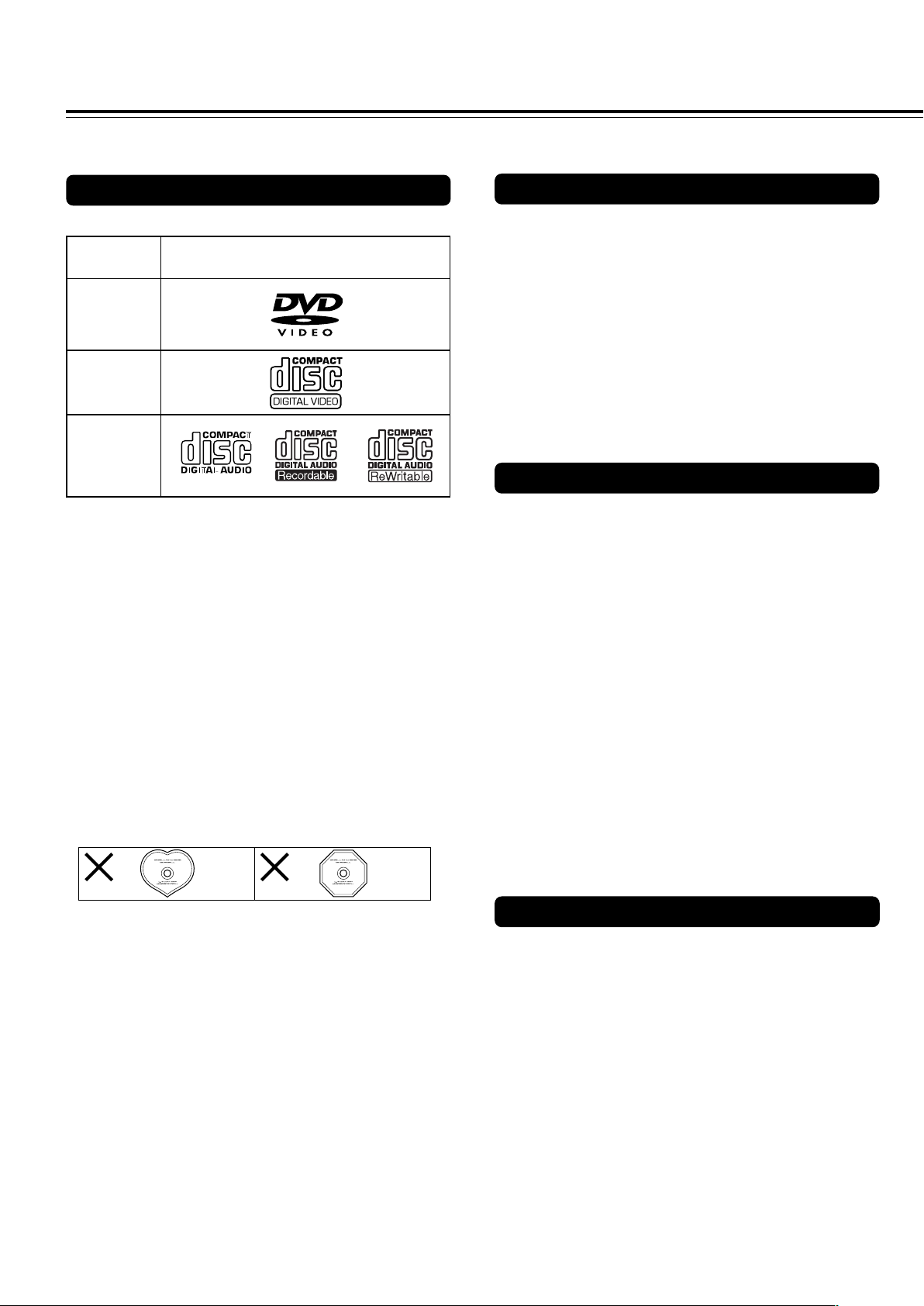
Playable Discs
This DVD Receiver can playback the following discs.
Disc mark
DVD videos
VIDEO CDs
*1 *1
Audio CDs
*1This unit can play CD-R and CD-RW discs recorded in CD
Audio or Video CD format, or with MP3 audio files.
However, there may be some discs that cannot be played
back with this unit. The causes of this impossibility include
incompletion of disc finalization and the recording
characteristics of the recorder as well as the properties,
damage or stain of the disc in use and stain or
condensation on the pickup lens of this unit. For details,
please refer to the instruction manual of the recorder.
• You cannot playback discs other than those listed above.
• You cannot play discs such as CD-ROM, DVD-RAM, DVD-
RW, DVD-Audio, Photo CD, CD-G etc., even if the marks in
the above table are labeled on those discs.
• This DVD Receiver uses the PAL/NTSC color system, and
cannot playback DVD videos recorded in any other color
system (SECAM, etc.).
• Avoid using heart-shaped or octagonal discs. Playing
irregularly shaped discs may damage the internal
mechanism of the DVD Receiver.
About VIDEO CDs
This DVD Receiver supports VIDEO CDs equipped with the
PBC (Version 2.0) function. (PBC is the abbreviation of
Playback Control.)
You can enjoy two playback variations depending on the type
of disc.
• VIDEO CD not equipped with PBC function (Version 1.1)
Sound and movies can be played on this DVD Receiver in
the same way as an audio CD.
• VIDEO CD equipped with PBC function (Version 2.0)
In addition to operation of the VIDEO CD not equipped with
the PBC function, you can enjoy playback with interactive
software and search function using the menu displayed on
the TV screen (Menu Playback). Some of the functions
described in this Instruction Manual may not work with some
discs.
MP3 compatibility information
• The CD-ROM must be ISO9660 compatible.
• Files should be MPEG1 Audio Layer 3 format, 44.1 or
48kHz, fixed bit-rate. Incompatible files will not play and
“UNPLAYABLE” will be displayed.
• This DVD Receiver is not compatible with variable bit-rate
(VBR) files. Be sure to make MP3 CD with fixed bit-rate
setting.
• This system only plays tracks that are named with the file
extension “.mp3” or “.MP3”.
• This system is not compatible with multi-session discs. If
you try an play a multi-session disc, only the first session
will be played.
• Use CD-R or CD-RW media for recording your MP3 files.
The disc must be finalized in order to play.
• Audio encoded at 128kbps should sound close to regular
audio CD quality. Although this system will play lower bitrate MP3 tracks, the sound quality becomes noticeably
worse at lower bit-rates.
• Only the first 8 characters of folder and track names
(excluding the “.mp3” extension) are displayed.
• This system can recognize a maximum of 250 folders and
250 tracks. Discs containing more than 250 folders or tracks
will not play.
• Do not use discs that have residue from adhesive tape,
rental discs that have peeling labels, or discs that have
custom labels or stickers. Otherwise, you may not be able
to eject the discs or the DVD Receiver may become
inoperative.
8
Notes on Copyright
It is forbidden by law to copy, broadcast, show, broadcast on
cable, play in public, and rent copyrighted material without
permission.
DVD videos are copy protected, and any recordings made from
these discs will be distorted.
This product incorporates copyright protection technology that is
protected by method claims of certain U.S. patents and other
intellectual property rights owned by Macrovision Corporation
and other rights owners. Use of this copyright protection
technology must be authorized by Macrovision Corporation, and
is intended for home and other limited viewing uses only unless
otherwise authorized by Macrovision Corporation. Reverse
engineering or disassembly is prohibited.
Page 9
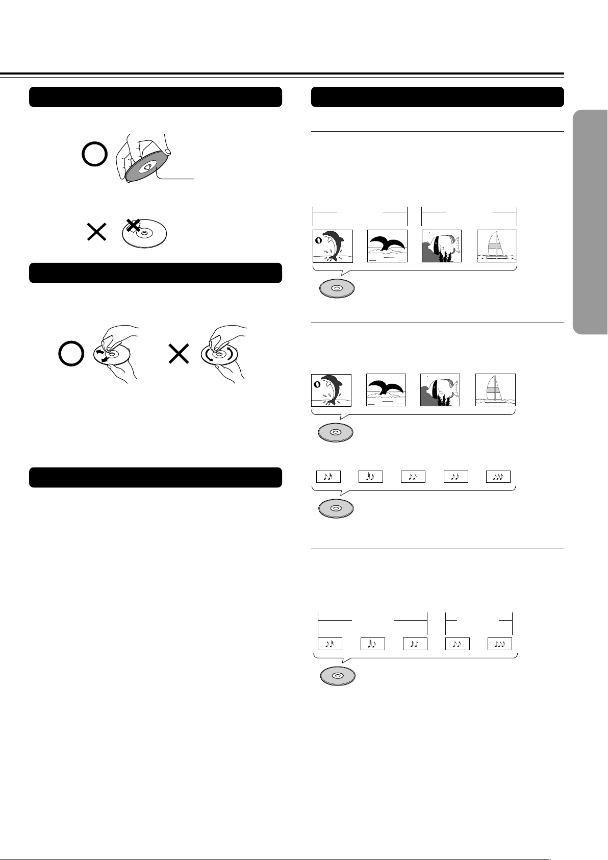
Handling Discs
Differences in Disc Composition
• Do not touch the playback side of the disc.
Playback side
• Do not attach paper or tape to discs.
Cleaning Discs
• Fingerprints and dust on the disc cause picture and sound
deterioration. Wipe the disc from the center outwards with a
soft cloth. Always keep the disc clean.
• If you cannot wipe off the dust with a soft cloth, wipe the disc
lightly with a slightly moistened soft cloth and finish with a
dry cloth.
• Do not use any type of solvent such as thinner, benzine,
commercially available cleaners or antistatic spray for vinyl
LPs. It may damage the disc.
Storing Discs
■ DVD
All discs are divided up into smaller, more manageable
sections so that you can find specific content more easily.
DVDs are divided into one or more titles. Each title may be
further divided into several chapters. Occassionally, a chapter
may contain index points, effectively dividing the chapter up
into several parts, too.
Chapter 1 Chapter 2
Title 1
DVD
Chapter 1
Title 2
Chapter 2
■ Video CD/CD
Video CDs and CDs are divided into a number of tracks. In
rare cases, a track may contain a number of index points,
effectively dividing the track up into several parts.
Track 1 Track 2 Track 3 Track 4
Video CD
Track 2 Track 4Track 3Track 1 Track 5
• Do not store discs in a place subject to direct sunlight or
near heat sources.
• Do not store discs in places subject to moisture and dust
such as a bathroom or near a humidifier.
• Store discs vertically in a case. Stacking or placing objects
on discs outside of their case may cause warping.
CD
■ MP3
MP3 (MPEG1 Audio Layer 3) is a compressed audio file
format. Files are recognized by their file extension “.mp3” or
“.MP3”. Folders that contain MP3 files are automatically
numbered F_001, F_002, etc. Tracks within folders are
automatically numbered T_001, T_002, etc.
Folder 1 Folder 2
Track 1
Track 2
MP3
Track 3
Track 2Track 1
9
Page 10
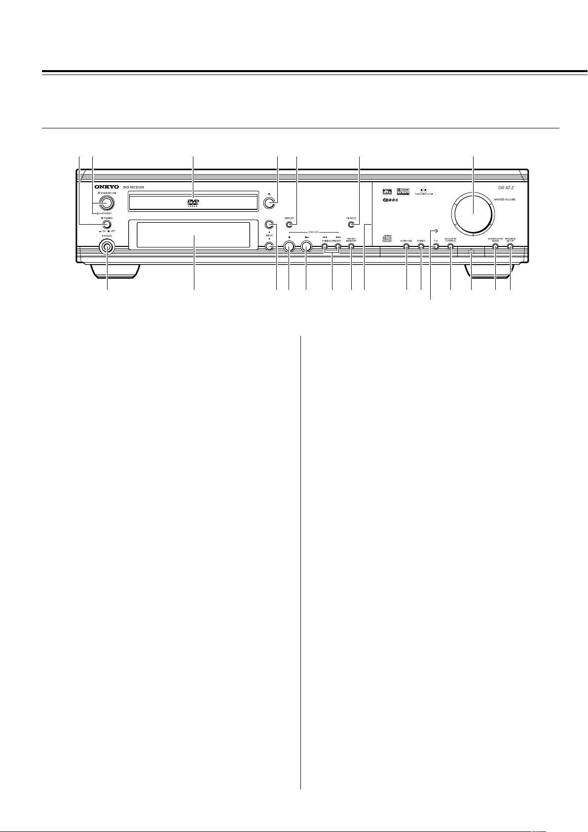
Index to Parts and Controls
For operational instructions, refer to the page indicated in brackets.
■Front panel
12 3 4 5 6 7
890-=~!#@$
1 (European and some Asian models only)
POWER switch [26]
Turns on the main power supply for the DVD Receiver. The DVD
Receiver enters standby state. Pressing the switch again to the off
position (— OFF) shuts down the main power supply into the DVD
Receiver.
Before turning on the power, make sure all cables are properly
connected.
2 STANDBY/ON button, STANDBY indicator [26, 37]
When STANDBY/ON button is pressed to ON (while the POWER
switch is set to ON on the European and some Asian models), the
DVD Receiver turns on. The STANDBY indicator turns off and the
display lights up. Pressing the button again returns the DVD
Receiver to the standby state. This state turns off the display,
disables control functions.
3 Disc tray [34]
When loading a disc, place discs in the disc tray with the label side
facing up.
4 0 button [34, 37]
Press to open and close the disc tray.
5 DISPLAY button [62, 63]
Press to change the information being displayed.
6 FM MODE button [38]
Press to switch the reception mode between stereo and monaural.
7 MASTER VOLUME control [42]
The MASTER VOLUME dial is used to control the volume level.
^*&(
%
= £ button [34, 37]
Press to start or resume playback.
~ TUNING/PRESET 4/¢ buttons [36, 38, 39]
Press to go back or advance to previous chapters/tracks. Also, use
these buttons to change the tuner frequency.
! PRESET MEMORY button [38, 39]
Press to assign the radio station that is currently tuned in to a
preset channel or delete a previously preset station.
@ Front panel illumination
# SURROUND button [48]
Press to select a surround mode.
$ STEREO button [48]
Press to change the listening mode to “Stereo”.
% T-D button, indicator [47]
Press to activate Theater-Dimensional mode. T-D indicator
illuminates in Theater-Dimentional mode. T-D indicator goes off
when other mode is selected.
^ ACOUSTIC CONTROL button [50]
Press to change the acoustic mode to boost the super bass/high
frequency sounds.
& Remote control sensor [15]
Point the remote control toward the remote sensor to operate the
DVD Receiver.
8 PHONES jack [42]
This is a standard stereo jack for connecting stereo headphones.
9 Display [11]
0 INPUT 5/∞ buttons [38, 39, 40]
Press to select the input source.
- 7 button [37]
Press to stop playback. Pressing once enables playback to resume
from a point shortly before the location where it was stopped.
Pressing twice causes the disc to return to the beginning of the
disc when playback starts again.
10
* SUBWOOFER MODE button [31]
Press to select the subwoofer mode.
( (North American and South American model)
SPEAKER A/B button [29, 42]
Press to switch the speaker systems in use between A and B.
(Other models)
SPEAKER SETUP button [30]
Press to select the optimum speaker configuration.
Page 11
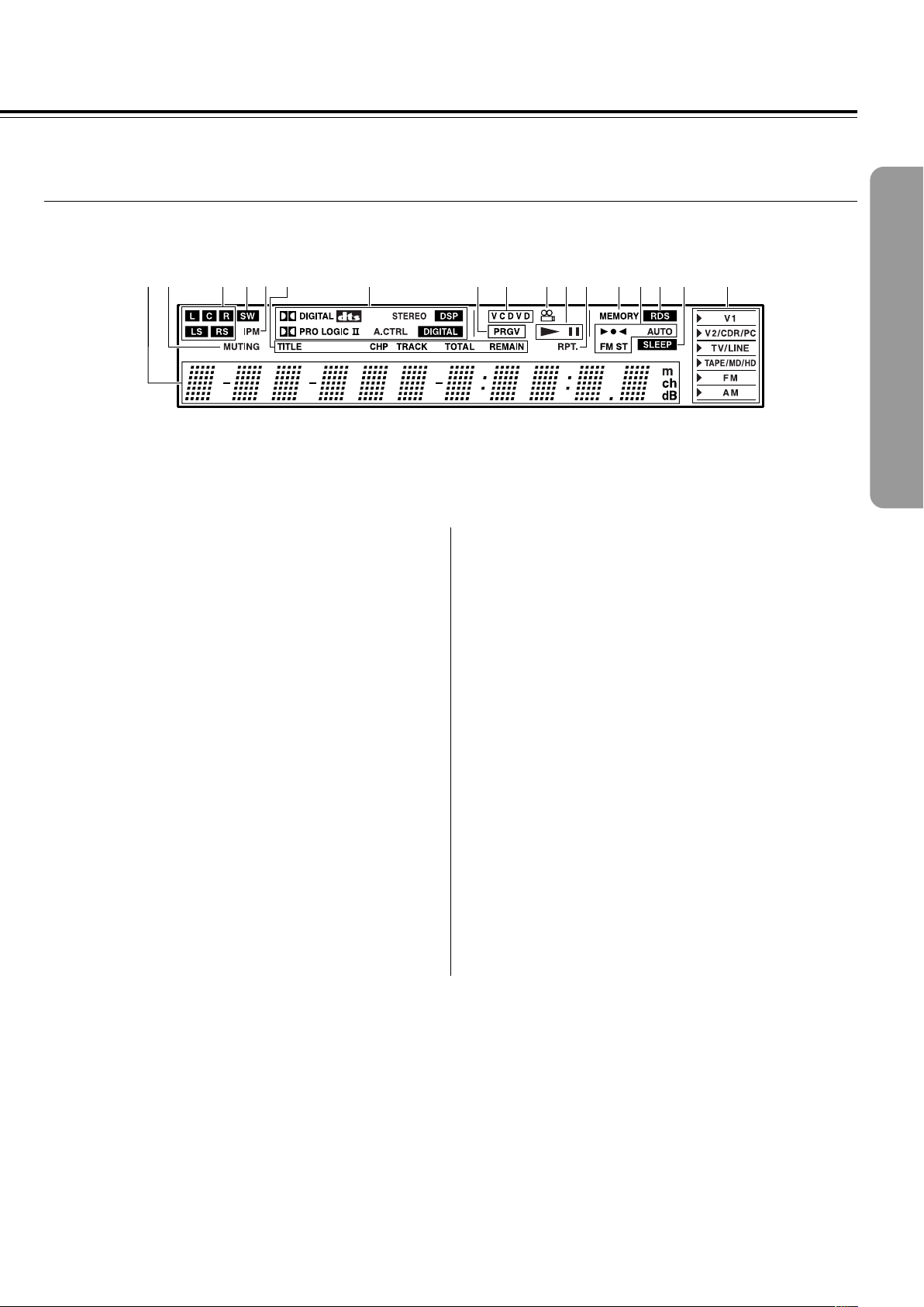
■ Display
213456 7 8 9 0-= ~ @!#$
1 Multipurpose display
2 MUTING indicator [42]
Flashes when the mute function is active.
3 Speaker setup indicators [29, 30]
Indicate the speaker configuration.
4 SW indicator [31]
Lights up when the subwoofer mode is set to SW Mode 1, 2 or 3.
5 IPM (Intelligent Power Management) indicator [22]
Lights up when the IPM function is active.
6 TITLE, CHP, TRACK, TOTAL, REMAIN indicators [62, 63]
Indicate display mode of the current chapter of DVD or track
number of Video CD or CD.
7 Source/Listening mode indicators [40, 45]
One of source indicators lights to show the format of the current
source. In addition, one of the listening mode indicators lights
according to the current listening mode.
8 PRGV indicator [67]
Lights up when the DVD Receiver is set to progressive-scan video.
9 Inserted disc indicator [34]
Indicates the type of current disc that is loaded.
0 Angle indicator [60]
Lights up while playing a scene recorded with multiple angles.
- £, 8 indicators [34]
Illuminates in play or pause mode.
= RPT. indicator [54]
Illuminates during repeat playback. Also RPT. indicator illuminates
during A-B repeat playback.
~ MEMORY indicator [38]
Lights up when the MEMORY button is pressed in the radio station
preset operation.
! 3¶2, AUTO, FM ST indicators [38]
Indicate the reception mode.
@ RDS indicator (European models only) [39]
Lights up when a RDS station is received.
# SLEEP indicator [43]
Lights up when the sleep timer is active.
$ Input source indicators [38, 40]
Show current input source.
11
Page 12
Index to Parts and Controls
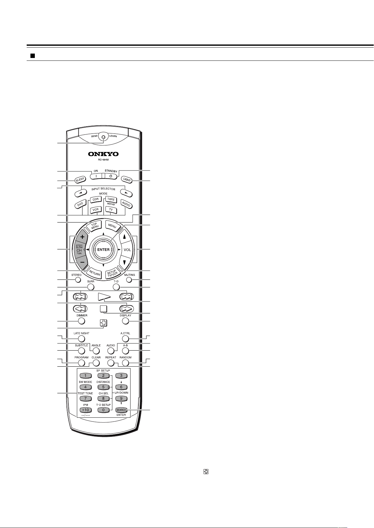
Remote controller
Explanations on this page are for controlling the DVD Receiver.
The supplied remote controller is a useful tool to help you operate of
your home theater.
To operate other components, see “Operating the Onkyo MD
Recorder/CD Recorder/Cassette Tape Deck/Hard Disk Recorder With
the Supplied Remote Controller” on page 41 and “Controlling other
components connected to the DVD Receiver” on pages 78-83.
1
2
3
*
(
4
5
6
7
8
9
0
)
_
+
¡
™
£
=
¢
∞
~
§
!
@
#
$
%
^
¶
•
ª
º
–
To control the DVD Receiver, press MODE DVD or MODE AUDIO
first. Press MODE DVD to operate DVD section, or MODE AUDIO
to operate receiver section. Functions of graied buttons in the
illustration vary depending on the mode.
1 SEND/LEARN indicator [15, 81, 83]
Lights red when sending a signal.
2 ON button [27]
Turns on the DVD Receiver.
3 SLEEP button [43]
For setting the sleep timer.
4 INPUT SELECTOR 2/3 buttons [39, 40]
Press to select the input source.
5 MODE buttons [15, 41, 78, 80, 82, 83]
For selecting the component to be operated by the remote
controller.
6 TOP MENU button [35, 53]
Press to call up the top menu programmed on the DVD. Depending
on the DVD, the top menu may be identical to the DVD menu.
7 (MODE AUDIO is selected)
CH +/– buttons [39]
For selecting a tuner preset channel.
(MODE DVD is selected)
STEP/SLOW +/– buttons [41]
Press STEP/SLOW +/– during playback to view still frame. Press
and hold STEP/SLOW +/– during playback to view slow playback.
In still frame, press STEP/SLOW + to advance DVDs and Video
CDs frame by frame and STEP/SLOW – to back up a few frames at
a time (DVD only).
8 RETURN button [35, 64]
Use to go one menu back (current settings are maintained). Use
RETURN when you do not want to change the option setting in a
menu.
9 STEREO button [48]
Press to change the listening mode to “Stereo”.
0 SURR button [48]
Press to select the surround mode.
12
&
≠
- 4/¢ buttons [35, 36]
During playback of DVD, CD and Video CD, press 4 to go back
to a previous chapter/track and ¢ to advance to the next chapter/
track .
= 1/¡ buttons [36]
During playback of DVD and Video CD, press ¡ to perform fast
forward scanning or 1 to perform fast reverse scanning of DVD
and Video CD. When a CD or MP3 is loaded, audio scanning is
performed.
~ DIMMER button [43]
For adjusting the brightness of the front display.
! button [34, 51]
Press to pause playback of a disc. Press again to resume
playback.
Page 13

@ LATE NIGHT button [50]
Press to change the late night setting.
+ VOL 5/∞ buttons [42]
For adjusting the volume.
# ANGLE button [60]
Some DVDs are recorded with various camera angle playback
options. Press ANGLE repeatedly to display different camera
angles.
$ SUBTITLE button [61]
Press repeatedly to select one of the subtitle languages
programmed on a DVD or to turn the subtitles off.
% PROGRAM button [53, 56, 57, 58]
You can program titles, chapters, or tracks to play back in a desired
order. Programs can be a maximum of 24 steps.
^ CLEAR button [53, 54, 57]
Works in conjunction with a number of player functions. Use to
cancel repeat and random playback, and to edit programs.
& (When MODE DVD is selected)
Number buttons (1-9, +10, 0) [35, 52, 78]
Use to perform direct title/folder and chapter/track searches, and to
input numerical values.
SEARCH button [52]
Press to perform a title/folder, chapter/track or elapsed time search.
(When MODE AUDIO is selected)
SW MODE button [31]
Press to select the subwoofer mode.
TEST TONE button [33, 49]
Outputs a test tone for setting speaker levels.
IPM (Intelligent Power Management) button [22]
Activates the IPM function.
SP SETUP button [29, 30]
Press to select the optimum speaker configuration.
¡ SETUP button [27, 64]
Press when the DVD Receiver is in either play or stop mode to
open and close the Setup screen.
™ MUTING button [42]
Activates the mute function.
£ T-D button [47]
Press to activate Theater-Dimensional mode.
¢ £ button [34, 37, 52]
Press to start or resume playback.
∞ 7 button [35, 37]
Press to stop playback. Pressing once enables playback to resume
from a point shortly before the location where it was stopped.
Pressing twice causes the disc to return to the beginning of the
disc when playback starts again.
§ DISPLAY button [62, 63]
Press to change the information being displayed.
¶ A.CTRL button [50]
Press to change the acoustic mode to boost the super bass/high
frequency sounds.
• AUDIO button [61]
Press repeatedly to select one of the audio languages programmed
on a DVD.
For Video CD, CD and MP3, each press changes the audio output
as follows.
→ Stereo → 1/L(Left) → 2/R(Right)
ª A-B button [54]
Press at the beginning and end of the section you want to repeat or
to mark a location you want to return to.
DISTANCE button [32]
For setting the distances for each speaker.
CH SEL button [33, 49]
Selects a speaker for changing the speaker output level.
T-D SETUP [47]
For setting the T-D parameters.
UP/DOWN 5/∞ [32, 33, 47, 49]
Press to adjust the value.
* STANDBY button [37]
Put the DVD Receiver in standby.
( LIGHT button
Illuminates the buttons. This button is useful when using the
remote controller in dark locations. When pressed, the buttons on
the remote controller light green.
) MENU button [35, 53]
Use to display or close the DVD menu or MP3 Navigator screen.
_ Cursor (2/3/5/∞/ENTER) [27, 34, 53, 64]
Use to move through the options on menu screens. Press to enter
settings.
º RANDOM button [55]
Press to play chapters/tracks in random order.
– REPEAT button [54]
Use to set the repeat mode.
≠ ENTER button [81-83]
Press to program the commands of remote controller for other
devices into the remote controller.
13
Page 14
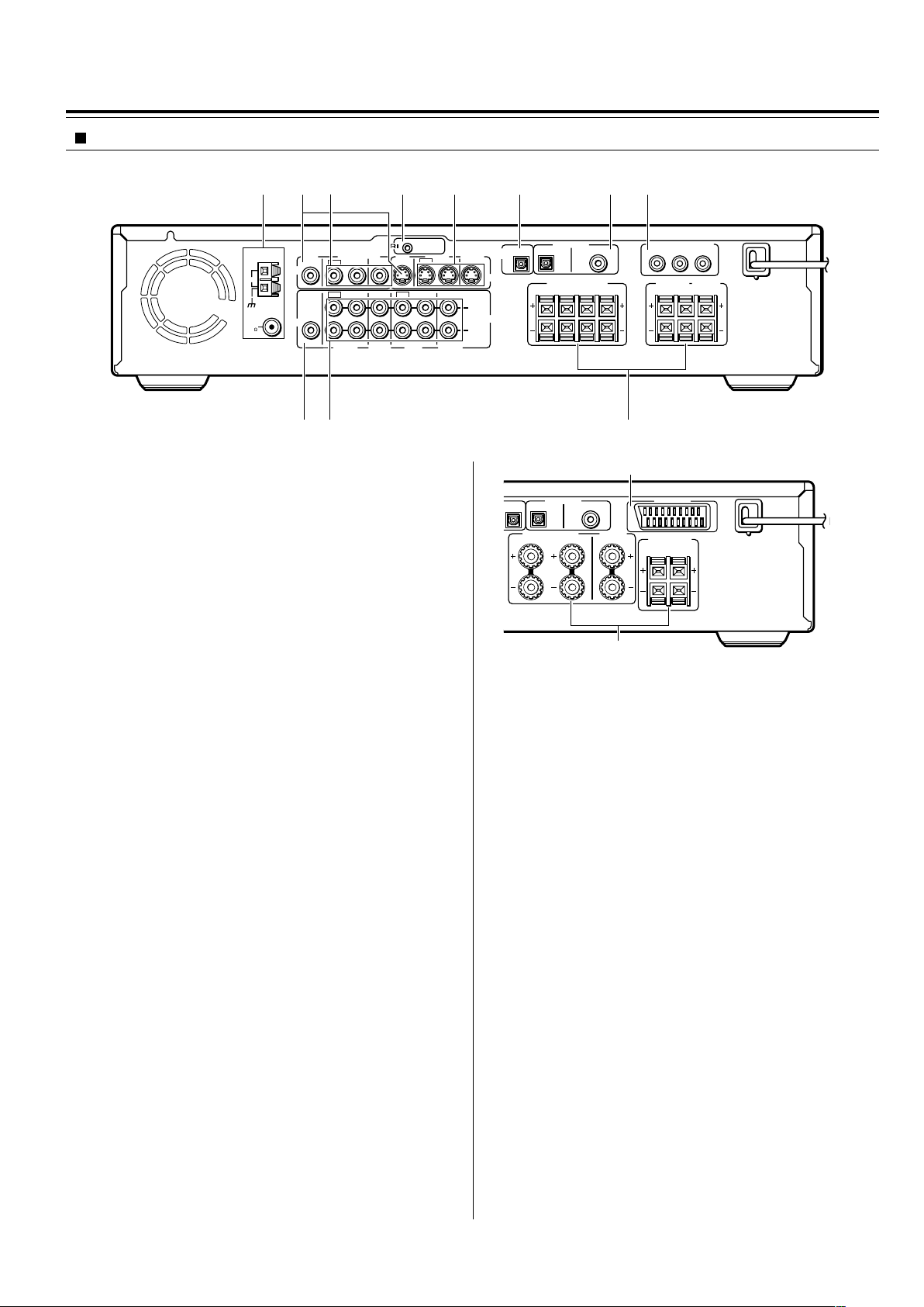
Index to Parts and Controls
Rear panel
12 4 5 6 783
REMOTE
ANTENNA
AM
FM
75
VIDEO
AUDIO
MON
2 ––VIDEO–– 1 VIDEO 2 VIDEO 1
OUT
OUT
IN
OUT
SUB
WOOFER
PRE OUT
IN OUT IN
VIDEO 1 TAPE
VIDEO2
CDR/PC
CONTROL
MON
OUT
OUT
IN
IN
MD/HD
90 -
Shapes of jacks vary depending on the area which it was purchased.
1 ANTENNA terminals [24, 25]
These terminals are for connecting the FM antenna and AM
antenna.
2 MON OUT jacks [16, 17]
The monitor output includes both RCA type and S video
configurations. This output is for connecting television monitor or
projector.
IN IN
IN
TV/LINE
North American and South
American model
OUTPUT
OPT
S VIDEO
L
AUDIO
R
OPT
COAX
FRONT SPEAKERS
BA
R
R
L
DIGITAL INPUT
VIDEO 2 VIDEO 1
OPT
COAX
FRONT SPEAKERS CENTER
L
R
DIGITAL INPUT
VIDEO 2 VIDEO 1
DIGITAL
L
SPEAKER
COMPONENT VIDEO OUTPUT
8
SURROUND
SPEAKERS
P
Y
SURROUND
SPEAKERS
R
AV CONNECTOR
R
L
B
P
R
CENTER
SPEAKER
L
European model
3 VIDEO (VIDEO 1 IN / VIDEO 2 IN/OUT) jacks [21]
There are 2 video inputs and 1 outputs. Connect LD players, VCRs
or other video components to the video inputs. The video output
channel can be used to connect video tape recorder for making
recordings.
4 z REMOTE CONTROL connector [23]
Connect the Onkyo components that have z connectors such as
a CD player, and cassette tape deck using the z cables provided
with them. When these components are interconnected, they can
be controlled from the remote controller provided with the DVD
Receiver.
After connecting the z connectors, check the operation of the
remote controller buttons for use in controlling other components.
5 S VIDEO (VIDEO 1 IN / VIDEO 2 IN/OUT) jacks [21]
There are 2 video inputs and 1 output. Connect LD players, VCRs
or other video components to the video inputs. The video output
channel can be used to be connected to video tape recorder for
making recordings.
6 DIGITAL OUTPUT OPT jack [21, 22]
This jack is for connecting MD recorder, CD recorder, hard disk
recorder or other component with optical fiber cable.
7 DIGITAL INPUT (VIDEO 1 COAX, VIDEO 2 OPT) jacks [21]
These are the digital audio inputs. There are 1 digital input with
optical jacks and 1 with a coaxial jack. The inputs accept digital
audio signals from MD players, hard disk recorders, CD players, or
other digital source component.
8 (European models)
AV CONNECTOR terminal [17]
Use a 21-pin SCART cable to connect to a TV or monitor
compatible with this type of connection. Both audio (2 channel
stereo) and video (Video, S-video, and RGB) signals are output
from the AV CONNECTOR.
-
(Other models)
COMPONENT VIDEO OUTPUT Y/P
If your TV or monitor has component video inputs, you can produce
a higher quality picture on your TV or monitor by connecting to the
component video outputs on this unit.
9 SUB WOOFER PRE OUT jack [18, 19]
This terminal is for connecting an active subwoofer.
0 AUDIO L/R (TV/LINE IN / TAPE/MD/HD IN/OUT /
VIDEO 1 IN / VIDEO 2/CDR/PC IN/OUT) jacks [16, 17]
These are the analog audio inputs and outputs. There are 4 audio
inputs and 2 audio outputs. The audio inputs and outputs require
RCA type connectors.
When connecting a VCR or other video component, make sure you
connect the audio and video leads together (i.e., both to VIDEO 1).
- (North American and South American model)
FRONT SPEAKERS A/B, SURROUND SPEAKERS and
CENTER SPEAKER terminals [18]
FRONT SPEAKERS A system: To enjoy surround sound. Speaker
terminals are provided for the front left, front right, center, surround
left and surround right speakers.
FRONT SPEAKERS B system: To enjoy stereo sound. Speaker
terminals are provided for the front left and front right.
(Other models)
FRONT SPEAKERS, CENTER SPEAKER and SURROUND
SPEAKERS terminals [19]
Speaker terminals are provided for the front left, front right, center,
surround left and surround right speakers. Speaker outputs are
compatible with banana plug connectors.
B/PR jacks [16]
14
Page 15
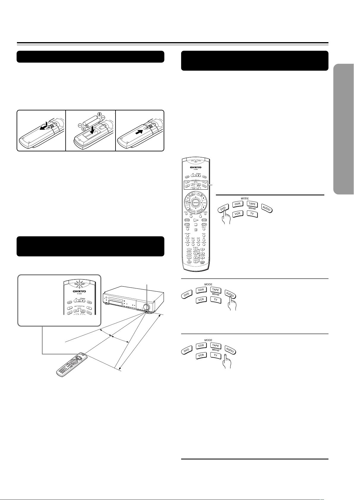
Preparing the Remote Controller
Inserting the Batteries
1 Detach the battery cover.
2 Insert the two size AA/R6/UM3 batteries.
Be sure to match the + and – ends of the batteries with
the diagram inside the battery compartment.
3 Attach the battery cover.
12
Notes
• Do not mix new batteries with old batteries or different kinds of
batteries.
• To avoid corrosion, remove the batteries if the remote controller
is not to be used for a long time.
• Remove dead batteries immediately to avoid damage from
corrosion. If the remote controller does not operate smoothly,
replace both batteries at the same time.
• The life of the supplied batteries is about six months but this
varies depending on usage.
3
Switching the remote controller
function modes
Some buttons on the remote controller have two or
more functions. To set the functionality of these
buttons, press one of the six MODE (DVD, CDR, TAPE/
MD/HD, AUDIO, VCR, TV) buttons in advance.
The function mode remains the same until another
MODE button is pressed.
(Details about the functions and the related function
modes are explained in each section.)
MODE buttons
Pointing the remote controller in the
right direction
Point the remote controller toward the remote control
sensor.
The SEND/
LEARN indicator
is lit while any
button on the
remote controller
is pressed.
30˚
Notes
• Place the unit away from strong light such as direct sunlight or
inverted fluorescent light which can prevent proper operation of
the remote controller.
• Using another remote controller of the same type in the same
room or using the unit near equipment which uses infrared rays
may cause operational interference.
• Do not put any object (such as a book) on the remote controller.
The buttons of the remote controller may be pressed by mistake
and drain the batteries.
• Make sure the audio rack doors do not have colored glass.
Placing the unit behind such doors may prevent proper remote
controller operation.
• If there is any obstacle between the remote controller and the
remote control sensor, the remote controller will not operate.
Remote control sensor
30˚
About 5 m (16 feet)
Press MODE DVD first before operating
the built-in DVD player.
Press MODE AUDIO first before operating the speaker
setting and sound related operations.
Press MODE CDR first before operating the
z-connected Onkyo CD recorder (see pages 21, 23
and 41)
Press MODE TAPE/MD/HD first before operating the
z-connected Onkyo MD recorder, cassette tape deck
or hard disk recorder (see pages 21, 23 and 41).
Press MODE VCR or MODE TV first before operating
your VCR or TV.
To operate the TV with the supplied remote controller,
you need to let the remote controller learn the TV
remote control signals (see pages 78 and 79).
15
Page 16
Connecting to a TV (Other than European model)
Before connecting
• Refer also to the instruction manual of the TV.
• When you connect the DVD Receiver to the TV, be sure to turn
off the power and unplug both the units from the mains before
making any connections.
• Connect the DVD Receiver to the TV directly. If you connect the
DVD Receiver to a VCR, TV/VCR combination, or video selector,
the playback picture may be distorted as DVD videos are copy
protected.
■ Connecting to a TV (or projector)
Using the supplied audio/video connection cable, make
audio connections from the TV/LINE IN L and R jacks to
the corresponding audio output jacks on the TV. In the
same manner, make video connections from the VIDEO
MON OUT jack to the corresponding video input jack on
the TV.
If your TV has a S video input jack and/or component video
input jacks, make S video connection to the S VIDEO MON
OUT jack using supplied S video connection cable and/or
make component video connection to the COMPONENT
VIDEO OUTPUT jacks using component video connection
cable (not supplied). These connections allow you to enjoy
higher quality picture playback. Be sure not to disconnect
VIDEO MON OUT.
• Connect the plugs securely.
Incomplete
• Note that one audio/video connection
cable and one S video connection cable
are supplied.
Insert completely
Notes
• Actual labels for component video inputs may vary depending
on the TV manufacturer (ex. Y/CB/CR, Y/B-Y/R-Y, etc.).
• In some TVs, the color levels of the playback picture may be
reduced slightly or the tint may change. In such a case, adjust
the TV for optimum performance.
Be sure to set the digital output setting after
connection using the Setup Navigator explained in
“Setting Up the DVD Receiver” starting on page 27
or the function setting menu explained in
“Customizing the Function Settings” starting on
page 64.
Video
(Yellow)
Note
The signal that comes in from
S VIDEO IN is sent to S
VIDEO OUT. The signal that
comes in from VIDEO IN is
sent to VIDEO OUT.
ANTENNA
TV or projector
S VIDEO
VIDEO
AUDIO
OUT
RL YP
VIDEO
AM
SUB
WOOFER
PRE OUT
AUDIO
FM
75
IN
IN
MON
2 ––VIDEO–– 1 VIDEO 2 VIDEO 1
OUT
OUT
IN
IN
OUT
IN OUT IN
IN
VIDEO 1 TAPE
VIDEO2
CDR/PC
COMPONENT
VIDEO IN
BPR
REMOTE
CONTROL
MON
OUT
OUT
MD/HD
IN IN
IN
TV/LINE
L (White)
Audio/video connection cable
R (Red)
Y
P
B
PR
Component video
connection cable
S video connection cable
Signal flow
OUTPUT
OPT
S VIDEO
L
AUDIO
R
OPT
COAX
FRONT SPEAKERS CENTER
L
R
DIGITAL INPUT
VIDEO 2 VIDEO 1
DIGITAL
SPEAKER
COMPONENT VIDEO OUTPUT
P
B
P
Y
SURROUND
SPEAKERS
R
L
R
DO NOT connect the
power cord (mains lead)
at this time.
16
See “Turning the unit on/off with the TV’s power
switch — IPM function” on page 22 for Inteligent
Power Management (IPM) function.
Page 17
Connecting to a TV (European model)
Before connecting
• Connect the plugs securely.
• Refer also to the instruction manual of the TV.
• When you connect the DVD Receiver to the TV, be sure to turn
off the power and unplug both the units from the mains before
making any connections.
• Connect the DVD Receiver to the TV directly. If you connect the
DVD Receiver to a VCR, TV/VCR combination, or video selector,
the playback picture may be distorted as DVD videos are copy
protected.
■ Connecting to a TV Using the SCART Cable
Connect the DVD Receiver and your TV using the supplied SCART cable.
If the TV is compatible with S video signals
After completing the steps on page 26, set “Video Out” to “S Video” using the menu
explained in “Customizing the Function Settings” starting from page 64. See page 67 for
direct information.
If an RGB monitor is connected to the DVD Receiver
After completing the steps on page 26, set “Video Out” to “RGB” using the menu explained
in “Customizing the Function Settings” starting from page 64. See page 67 for direct
information.
Be sure to set the digital output setting after connection using the
Setup Navigator explained in “Setting Up the DVD Receiver” starting
on page 27 or the function setting menu explained in “Customizing
the Function Settings” starting on page 64.
Incomplete
Insert completely
TV or projector
AC
CONNECTOR
SCART cable
To AC CONNECTOR
input terminal
REMOTE
CONTROL
MON
OUT
OUT
IN
IN
TV/LINE
MD/HD
Video
(Yellow)
ANTENNA
AM
FM
75
VIDEO
AUDIO
MON
2 ––VIDEO–– 1 VIDEO 2 VIDEO 1
OUT
OUT
IN
OUT
SUB
WOOFER
PRE OUT
IN OUT IN
VIDEO 1 TAPE
VIDEO2
CDR/PC
L (White)
Audio/video
R (Red)
connection cable
S video connection cable
Signal flow
■ Connecting to a TV usinf the Audio/Video
connection cable or S video connection
cable
If the TV or monitor does not has an AV CONNECTOR
input terminal, make video connection using audio/video
connection cable.
If your TV has an S video input jack, make the S video
connection. The S video connection will provide higher
quality picture playback. Be sure not to disconnect VIDEO
MON OUT.
AV CONNECTOR
SURROUND
SPEAKERS
R
L
IN IN
IN
OUTPUT
OPT
S VIDEO
L
AUDIO
R
OPT
COAX
FRONT SPEAKERS CENTER
R
SPEAKER
L
DIGITAL INPUT
VIDEO 2 VIDEO 1
DIGITAL
See “Turning the unit on/off with the TV’s power
switch — IPM function” on page 22 for Inteligent
Power Management (IPM) function.
R
AUDIO
OUT
L
VIDEO
IN
S VIDEO
IN
DO NOT connect the
power cord (mains lead)
at this time.
TV or projector
17
Page 18
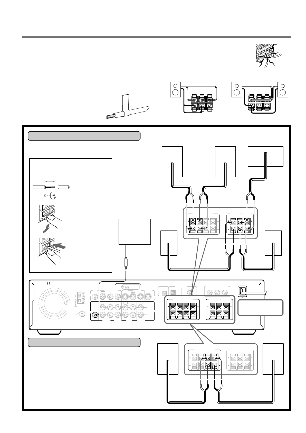
Connecting Speakers (North American and South American model)
Before connecting
• Refer also to the instruction manuals of the speakers.
• This DVD Receiver is designed to reproduce optimum sound
quality when speakers with the impedances specified below are
connected. Please check the following information and choose
speakers with appropriate impedances for the connections.
Front speakers: 6 ohms min. per speaker
Center speaker: 6 ohms min.
Surround Speakers : 6 ohms min. per speaker
• Attach supplied speaker labels to
speaker cables to connect speakers
correctly.
Connecting to SPEAKERS A
The main speaker system is SPEAKERS A.
Follow the illustration on the right.
How to connect to the speaker
connectors
10 mm (3/8”)
Strip 10 mm (3/8”)
from the end of
each cord, then
twist the exposed
wires tightly.
• To prevent damage to circuits, never shortcircuit the positive (+) and negative (–)
speaker wires.
• Do not connect the speaker cable to the L
and R connectors at the same time and do
not connect more than one speaker to the
same speaker connectors.
LR
+
–
+
–
NO!
LR
+
–
Front (R) Front (L) Center
+–
+–+–
+
–
NO!
NO!
Press and hold
the lever.
Active
subwoofer
Insert the stripped
end of the cord.
By releasing the
lever, the lever is
replaced.
REMOTE
ANTENNA
AM
FM
75
VIDEO
AUDIO
MON
2 ––VIDEO–– 1 VIDEO 2 VIDEO 1
OUT
OUT
IN
OUT
SUB
WOOFER
PRE OUT
IN OUT IN
VIDEO 1 TAPE
VIDEO2
CDR/PC
CONTROL
MON
OUT
IN
IN
MD/HD
Connecting to SPEAKERS B
To place the additional speaker system (for the second
room), make the SPEAKERS B connection on the right.
SURROUND
SPEAKERS
R
CENTER
SPEAKER
L
Surround
(L)
Surround
(R)
FRONT SPEAKERS
A
R
R
L
B
L
+– +–
IN IN
OUT
IN
TV/LINE
OUTPUT
OPT
S VIDEO
L
AUDIO
R
OPT
COAX
FRONT SPEAKERS
R
R
L
BA
DIGITAL INPUT
VIDEO 2 VIDEO 1
DIGITAL
Front (R)
L
FRONT SPEAKERS
A
R
L
COMPONENT VIDEO OUTPUT
P
B
P
Y
SURROUND
SPEAKERS
R
R
CENTER
SPEAKER
L
R
B
L
DO NOT connect the
power cord (mains lead)
at this time.
SURROUND
CENTER
SPEAKERS
SPEAKER
L
R
Front (L)
18
+–+–
Page 19
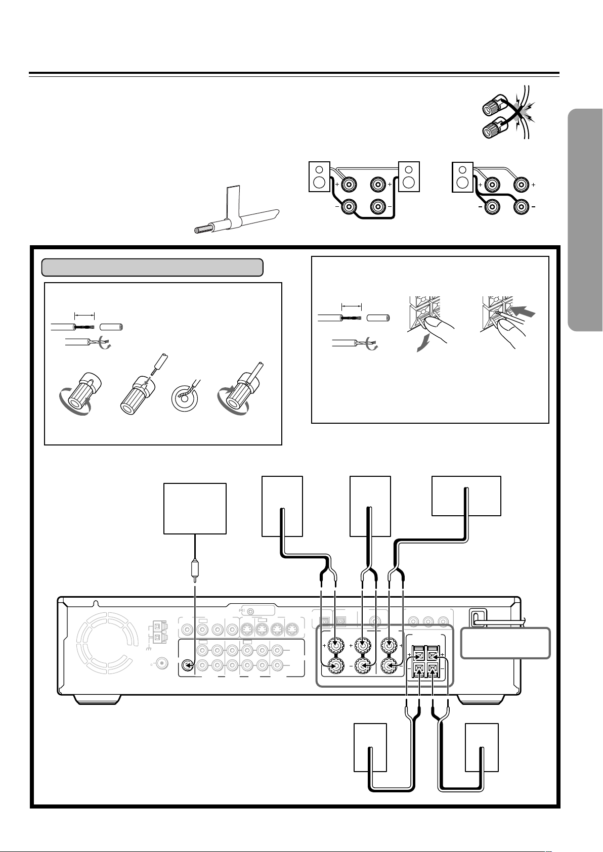
Connecting Speakers (Other models)
Before connecting
• Refer also to the instruction manuals of the speakers.
• This DVD Receiver is designed to reproduce optimum sound
quality when speakers with the impedances specified below are
connected. Please check the following information and choose
speakers with appropriate impedances for the connections.
Front speakers: 6 ohms min. per speaker
Center speaker: 6 ohms min.
Surround Speakers : 6 ohms min. per speaker
• Attach supplied speaker labels to
speaker cables to connect speakers
correctly.
Connecting to SPEAKERS
How to connect to the FRONT SPEAKER terminals
15 mm
Strip 15 mm from the end of each
cable, then twist the exposed wires
tightly.
Loosen the screw. Fully insert the end
of the cable.
Tighten the screw,
• To prevent damage to circuits, never shortcircuit the positive (+) and negative (–)
speaker wires.
• Do not connect the speaker cable to the L
and R connectors at the same time and do
not connect more than one speaker to the
same speaker connectors.
L
R
L
R
NO!NO!
How to connect to the SURROUND SPEAKERS
and CENTER SPEAKER terminals
10 mm
Strip 10 mm from
the end of each
cable, then twist
the exposed
wires tightly.
Press and hold
the lever.
Insert the stripped
end of the cord.
By releasing the
lever, the lever is
replaced.
NO!
ANTENNA
AM
FM
75
Active
subwoofer
MON
2 ––VIDEO–– 1 VIDEO 2 VIDEO 1
OUT
SUB
WOOFER
PRE OUT
OUT
OUT
VIDEO2
CDR/PC
VIDEO
AUDIO
MON
OUT
IN
IN
IN OUT IN
IN
VIDEO 1 TAPE
MD/HD
Front (R) Front (L) Center
+–+–
REMOTE
CONTROL
OUT
IN IN
IN
TV/LINE
OUTPUT
OPT
S VIDEO
L
AUDIO
R
OPT
COAX
FRONT SPEAKERS CENTER
L
R
DIGITAL INPUT
VIDEO 2 VIDEO 1
DIGITAL
Surround (R)
SPEAKER
COMPONENT VIDEO OUTPUT
P
B
P
SURROUND
SPEAKERS
R
R
L
Y
Surround (L)
+–
DO NOT connect the
power cord (mains lead)
at this time.
+– +–
19
Page 20
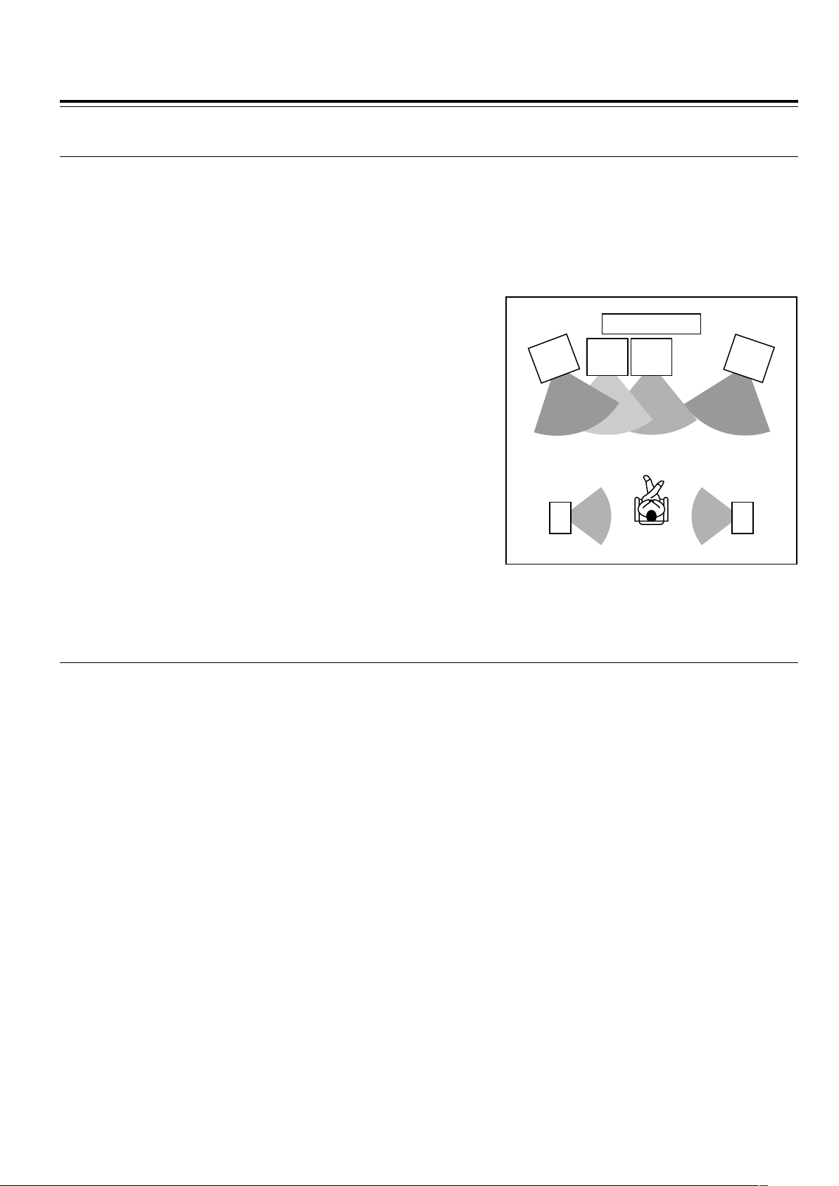
Positioning Speakers
■ Standard speaker placement of the speakers system (standard speaker placement of the
SPEAKERS A system for North American and South American model)
Speaker placement plays an important role in the reproduction of Surround sound. The placement of the speakers varies depending
on the size of the room and the wall coverings used in the room. The illustration below shows an example of a layout for standard
speaker placement. Refer to this example when you position the speakers in order to experience the best of Surround sound.
For ideal Surround effects, all speakers should be installed.
If a center speaker or subwoofer is not connected, the sound from the unused channel is properly distributed to the connected
speakers in order to reproduce the best Surround sound possible.
Front
The center speaker reproduces a richer sound image by enhancing the
perception of the sound's source and movement.
The left, right, and center speakers should face the seated listener and be
placed at ear level.
Surround
The surround speakers reproduce the feel of a moving sound while creating
the sensation of being in the middle of the action.
Place the left and right surround speakers 1 meter (3 feet) above the
listener's ear level and facing toward the sides of the room, making sure that
the listener is within the speakers’ dispersion angle.
Front
left
Speaker
Surround
left
Speaker
Sub-
woofer
TV/Screen
Front
Center
Speaker
Front
right
Speaker
Surround
right
Speaker
Subwoofer
Install a subwoofer with a built-in power amplifier for powerful bass sounds.
The placement of the subwoofer does not affect the final quality of the sound
image much, therefore, you can install it wherever it is convenient.
Refer to the speakers’ instruction manuals for details.
■ For North American and South American models
Two speaker systems (FRONT SPEAKERS A and FRONT SPEAKERS B) can be connected to the DVD Receiver.
For example, you can place the FRONT SPEAKERS A system in the main room, and the FRONT SPEAKERS B system in a
second room.
The configuration of the FRONT SPEAKERS A system
The FRONT SPEAKERS A system consists of the front left, center, and right speakers, surround left and right speakers, and
subwoofer.
You can reproduce the sounds such as Dolby surround and DTS surround.
The configuration of the FRONT SPEAKERS B system
The FRONT SPEAKERS B system consists of the front left and right speakers.
You can reproduce only monaural and stereo sounds.
20
Page 21
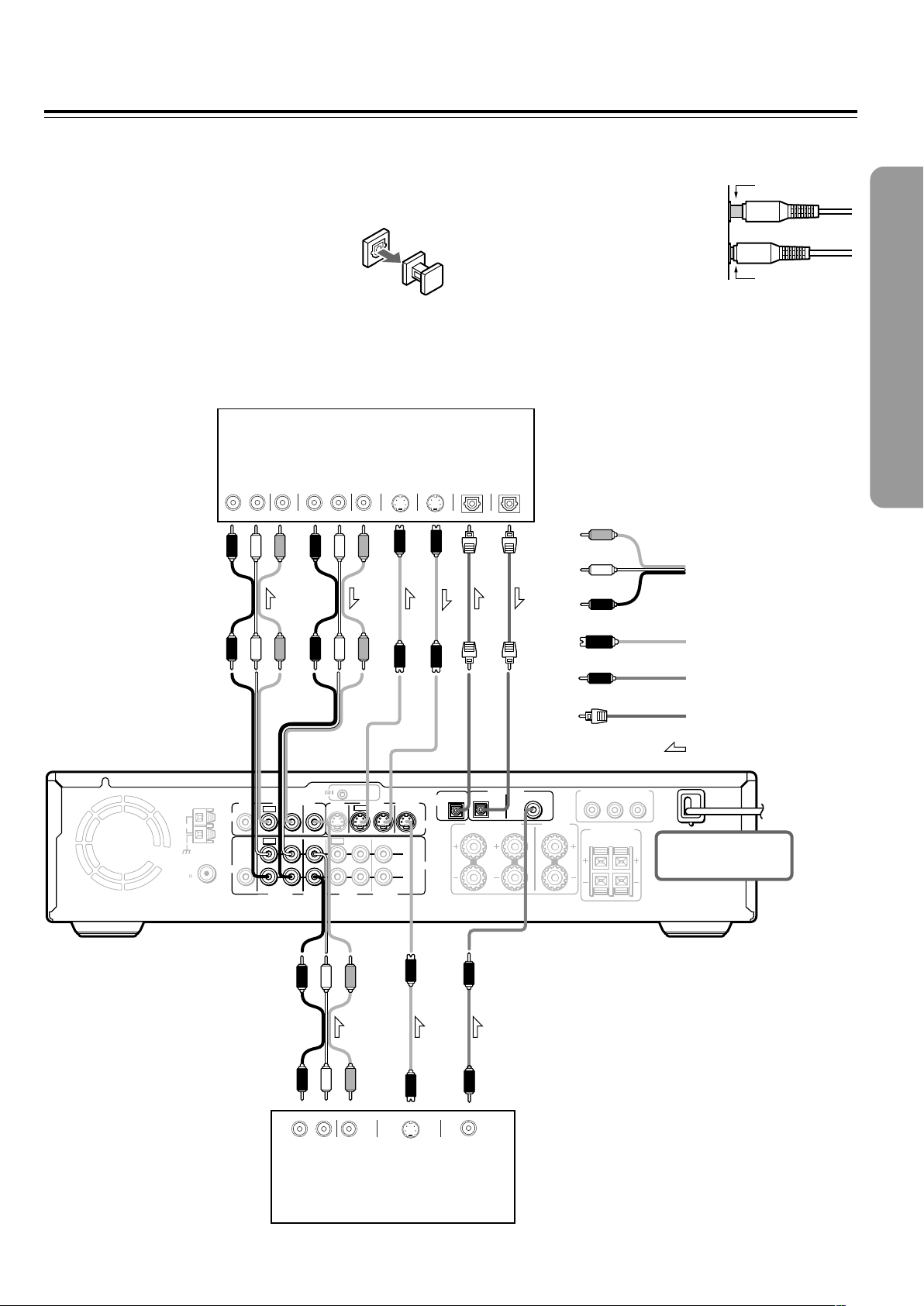
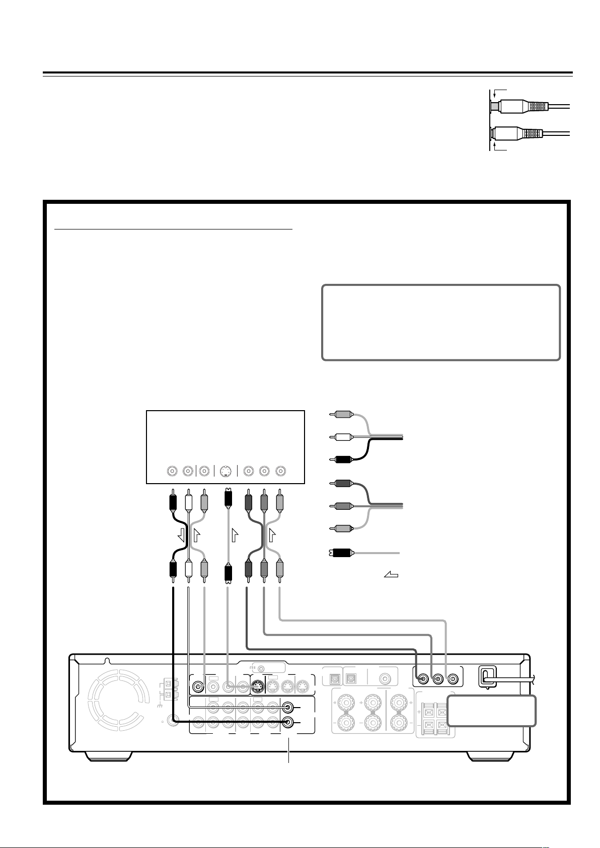
Connecting to Audio/Video Equipment
Before connecting
• Refer also to the instruction manual of each component to be
connected.
• When you connect the DVD Receiver to audio/video equipment, be
sure to turn off the power and unplug all the units from the mains before
making any connections.
• About the DIGITAL INPUT (OPT) and DIGITAL
OUTPUT (OPT) connectors
Remove the protective caps before making
connections. When not in use, be sure to replace them.
VCR, CD Recorder,
DVD Recorder etc.
VIDEO
AUDIO
RL RL
IN
IN
AUDIO
OUT
VIDEO
OUT
S VIDEO
IN
• About the VIDEO 1 and VIDEO 2 jacks/connectors
The video input/output connections are also necessary even if you
make the S video input/output connections.
• Connect the plugs securely.
• Note that one audio/video connection cable
and one S video connection cable are
supplied (if not used in the connection on
the opposite page).
DIGITAL
S VIDEO
OUT
IN
OPTICAL
DIGITAL
OUT
OPTICAL
Video
(Yellow)
L (White)
Audio/video connection
R (Red)
cable
Incomplete
Insert completely
ANTENNA
AM
FM
75
VIDEO
AUDIO
MON
2 ––VIDEO–– 1 VIDEO 2 VIDEO 1
OUT
OUT
IN
IN
OUT
IN OUT IN
VIDEO2
CDR/PC
IN
VIDEO 1 TAPE
SUB
WOOFER
PRE OUT
MON
OUT
MD/HD
REMOTE
CONTROL
OUT
IN IN
IN
TV/LINE
S video connection
cable
Coaxial cable
Optical fiber cable
Signal flow
OUTPUT
OPT
S VIDEO
L
AUDIO
R
OPT
COAX
FRONT SPEAKERS CENTER
L
R
DIGITAL INPUT
VIDEO 2 VIDEO 1
DIGITAL
SPEAKER
COMPONENT VIDEO OUTPUT
PB
PR
Y
SURROUND
SPEAKERS
R
L
DO NOT connect the
power cord (mains lead)
at this time.
RL
AUDIO
OUT
VIDEO
OUT
S VIDEO
OUT
COAXIAL
DIGITAL
OUT
Satellite tuner, LD Player, BS
digital tuner, Video Cassette
Player etc.
21
Page 22
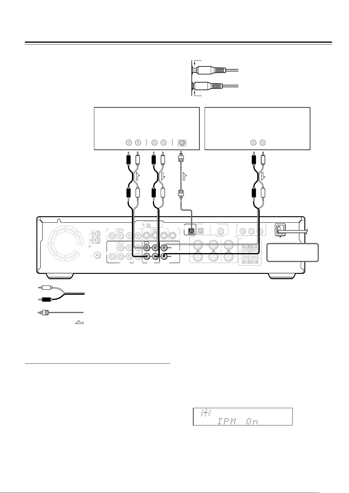
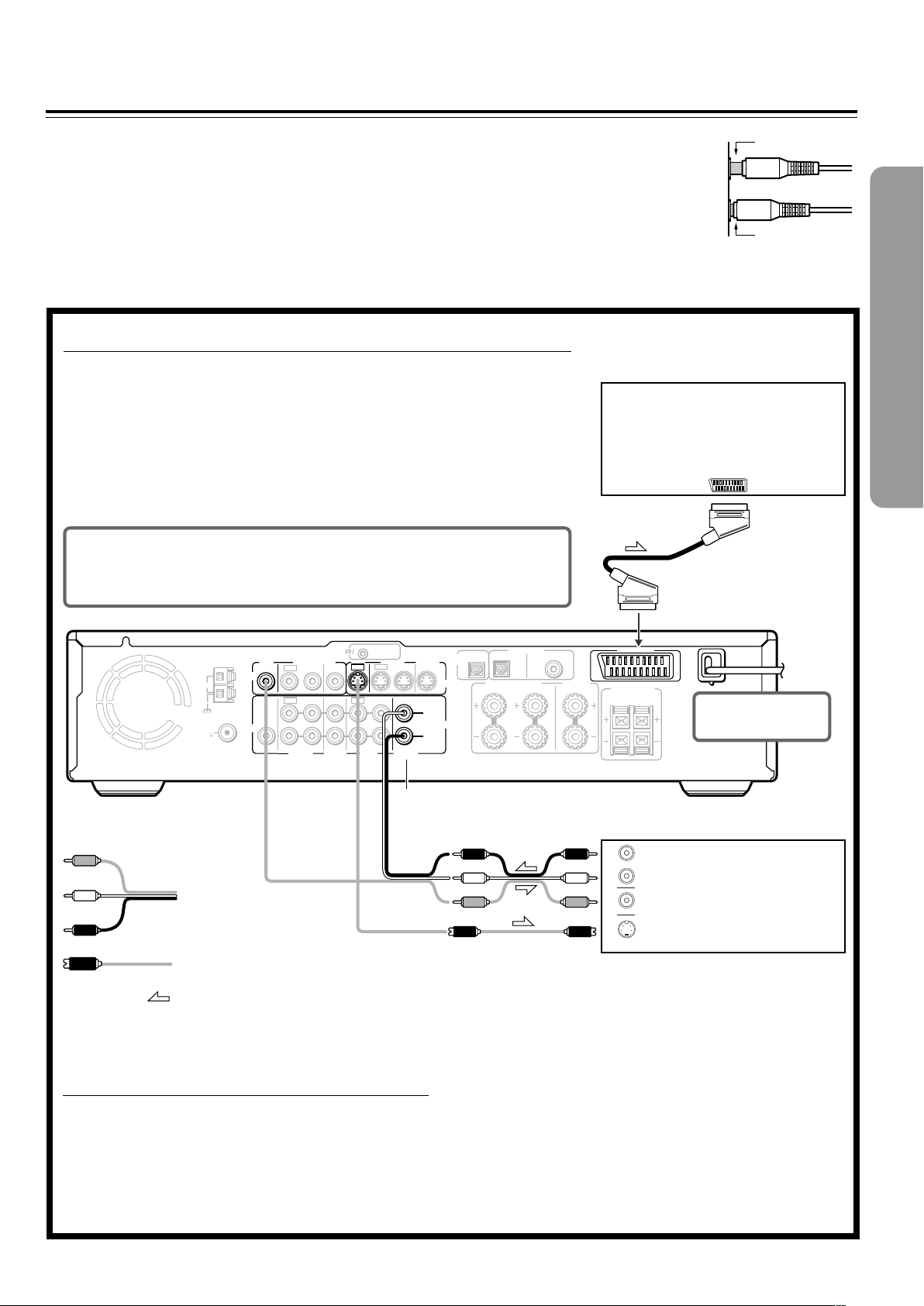
Connecting to Audio/Video Equipment
Before connecting
• Refer also to the instruction manual of each component to be
connected.
• When you connect the DVD Receiver to audio/video equipment, be
sure to turn off the power and unplug all the units from the mains
before making any connections.
MD Recorder, Cassette Tape Deck,
CD Recorder , Hard Disk
Recorder etc.
AUDI O
IN
RL RL
AUDIO
OUT
• Connect the plugs securely.
Incomplete
Insert completely
DIGITAL
IN
OPTICAL
TV
AUDIO
OUT
RL
REMOTE
ANTENNA
AM
FM
75
VIDEO
AUDIO
MON
2 ––VIDEO–– 1 VIDEO 2 VIDEO 1
OUT
OUT
IN
OUT
SUB
WOOFER
PRE OUT
IN OUT IN
VIDEO 1 TAPE
VIDEO2
CDR/PC
CONTROL
MON
OUT
OUT
IN
IN
TV/LINE
MD/HD
Audio connection cable
Optical fiber connection cable
Signal flow
■ Turning the unit on/off with the TV’s power
switch — IPM function
The DVD Receiver is equipped with the (IPM) system.
Just turn on your TV’s power switch and, in about 5 seconds,
the DVD Receiver turns on automatically. If you turn off the
TV’s power switch, IPM indicator flashes on the display and
the DVD Receiver automatically turns off in about 5 minutes.
IN IN
IN
OUTPUT
OPT
S VIDEO
L
AUDIO
R
OPT
COAX
FRONT SPEAKERS CENTER
L
R
DIGITAL INPUT
VIDEO 2 VIDEO 1
DIGITAL
SPEAKER
COMPONENT VIDEO OUTPUT
PB
PR
Y
SURROUND
SPEAKERS
R
L
DO NOT connect the
power cord (mains lead)
at this time.
To activate the IPM function
1 Connect the audio output of your TV’s audio output to the
DVD Receiver’s TV/LINE IN L/R jacks (refer to pages 16 and
17).
Even when connected with SCART cable, audio connection
to TV/LINE IN L/R jacks is needed (European model).
2 Press IPM on the remote controller repeatedly until “IPM On”
appears on the display. The IPM indicator lights up on the
display.
22
Notes
• The IPM system may not function properly with some TV sets.
• When using monaural TV, connect the audio output of the TV to
the DVD Receiver’s TV/LINE IN L jack.
• When the TV is turned off while the DVD Receiver selects other
input source, the DVD Receiver does not turn off.
Page 23
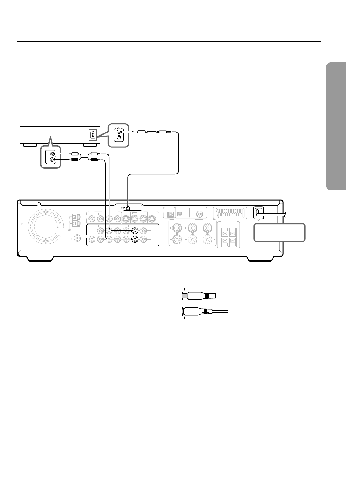
z Connection for the Onkyo MD
Recorder or Cassette Tape Deck
The supplied remote controller has the following extended functions in addition to operating the DVD Receiver:
• Operating the TV and VCR (see pages 78-80)
• Operating the z connected Onkyo MD recorder, CD Recorder, Hard Disk Recorder or cassette tape deck (see page 41).
The z cable which is needed to make the z connection is supplied with the Onkyo MD recorder, CD Recorder, Hard Disk
Recorder or cassette tape deck.
If you start playing back the MD Recorder, CD Recorder, Hard Disk Recoder or cassette tape deck after making the z connection,
the DVD Receiver automatically changes its input source to TAPE/MD/HD — Direct Change function.
Onkyo MD recorder/HD
recorder/cassette tape deck
z cable
L
R
ANALOG
OUTPUT
Be sure to connect
using the audio
connection cable.
REMOTE
ANTENNA
AM
FM
75
VIDEO
AUDIO
MON
2 ––VIDEO–– 1 VIDEO 2 VIDEO 1
OUT
OUT
IN
OUT
SUB
WOOFER
PRE OUT
IN OUT IN
VIDEO 1 TAPE
VIDEO2
CDR/PC
CONTROL
MON
OUT
IN
IN
MD/HD
IN IN
OUT
IN
TV/LINE
Notes
• If the connected component has two z connectors, you can use
either one to connect to the DVD Receiver. The other one can be
used to daisy chain with another component.
• Do not connect the Onkyo MD recorder, Hard Disk Recorder and
cassette tape deck with the z cable at the same time. This may
lead to unexpected operation.
• Connect the plugs securely.
• Be sure to connect to the z connectors using the z cable.
• The connections on pages 21 and 22 are needed even if z
connection is made.
• Do not connect the DVD Receiver’s z connector to any
component other than an Onkyo product. It may cause
malfunction.
OUTPUT
OPT
S VIDEO
L
AUDIO
R
OPT
COAX
FRONT SPEAKERS CENTER
R
SPEAKER
L
DIGITAL INPUT
VIDEO 2 VIDEO 1
DIGITAL
AV CONNECTOR
SURROUND
SPEAKERS
R
L
DO NOT connect the
power cord (mains lead)
at this time.
Incomplete
Insert completely
2323
Page 24
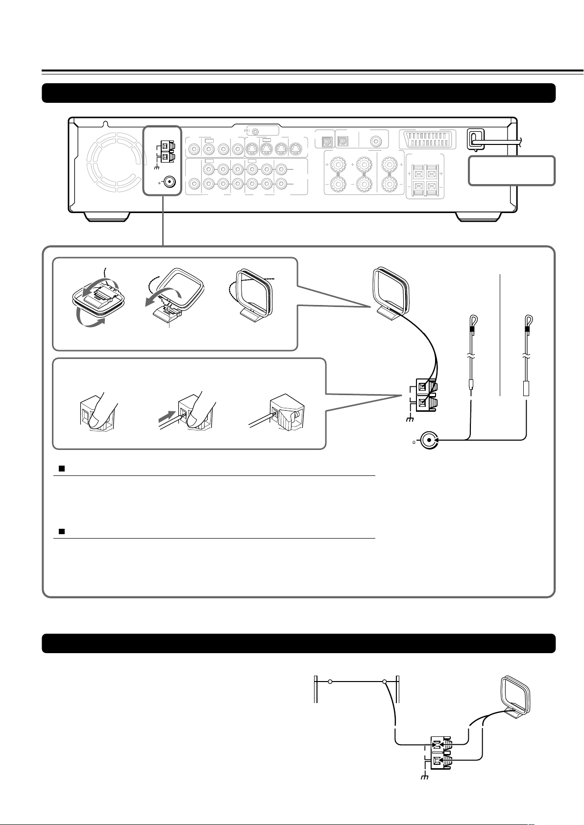
Making Antenna (Aerial) Connections
Connecting the Supplied FM and AM Indoor Antennas (Aerials)
Press up and
hold the lever.
ANTENNA
AM
FM
75
VIDEO
AUDIO
MON
OUT
SUB
WOOFER
PRE OUT
Insert into the hole.
Insert the end of
the cord.
REMOTE
CONTROL
2 ––VIDEO–– 1 VIDEO 2 VIDEO 1
OUT
OUT
VIDEO2
CDR/PC
MON
OUT
IN
IN
IN OUT IN
IN
VIDEO 1 TAPE
MD/HD
OUT
TV/LINE
Release the lever to
secure the connection.
IN IN
IN
OUTPUT
OPT
S VIDEO
L
AUDIO
R
OPT
COAX
FRONT SPEAKERS CENTER
R
SPEAKER
L
DIGITAL INPUT
VIDEO 2 VIDEO 1
DIGITAL
AM indoor antenna (aerial)
AV CONNECTOR
SURROUND
SPEAKERS
R
L
(North American
and South
DO NOT connect the
power cord (mains lead)
at this time.
FM indoor antenna (aerial)
(Other
models)
American
models)
ANTENNA
AM
Adjusting the position of the FM indoor antenna (aerial)
While listening to an FM program (see page 38), extend the antenna (aerial) and
move it in various directions until the clearest signal is received, then secure the
antenna (aerial) with push pins in the position with the least distortion.
Adjusting the position of the AM indoor antenna (aerial)
While listening to an AM program (see page 38), set the antenna (aerial) in the
direction and position where you receive the clearest sound.
Put it as far away as possible from the unit, TVs, speaker cables, and power cords
(mains leads).
Connecting an AM Outdoor Antenna (Aerial)
An outdoor antenna (aerial) will be more effective if it is stretched
horizontally above a window or outside.
Leave the supplied AM indoor antenna (aerial) connected.
Note
To avoid the risk of lightning and electrical shock, grounding is
necessary. Follow item 14 of the "Important Safeguards" on page 2 when
you install an outdoor antenna (aerial).
Outdoor antenna (aerial)
FM
75
Note
Insert one end of the AM antenna
(aerial) cord to either of the AM antenna
(aerial) connectors and the other end to
the other connector. There is no
difference between one end of the AM
antenna (aerial) cord and the other end,
unlike the speaker cords which have
positive and negative poles.
AM indoor antenna (aerial)
ANTENNA
2424
AM
Page 25
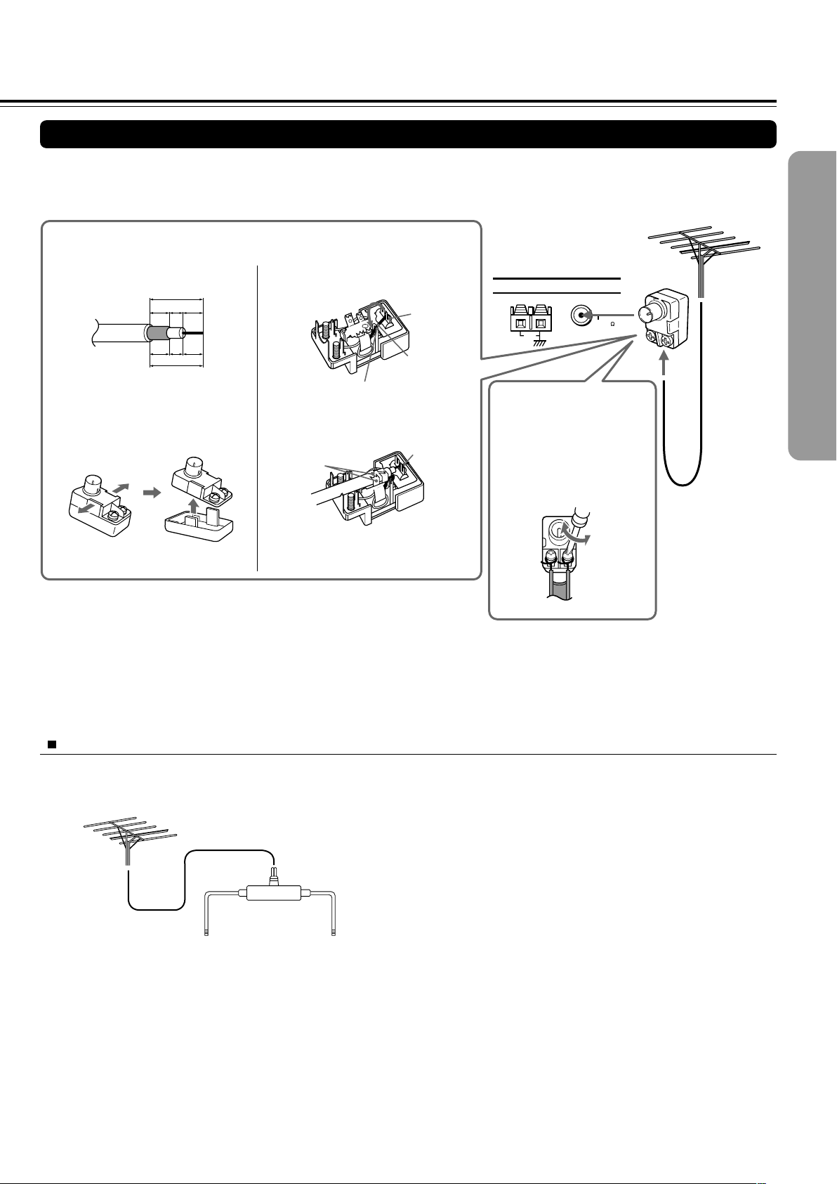
Connecting an FM Outdoor Antenna (Aerial)
If the FM reception is not very clear with the supplied antenna (aerial), connect an FM outdoor antenna (aerial) instead of the indoor
FM antenna (aerial).
FM outdoor antenna (aerial)
Connecting coaxial cable to a 75/300 ohm antenna (aerial) adapter*
1 Strip the end of the coaxial cable.
15 mm
3mm6
6
mm
mm
1
1
1
/8
/4
/4
in.
in.
in.
5
/8 in.
3 Remove the transformer wire A
from slit B and insert it into slit C.
Slit B
Wire A
Slit C
ANTENNA
FM 75
AM
Connecting 300 ohm ribbon
wire to a 75/300 ohm
2 With your fingernail or a small
screwdriver, press the stoppers
outward and remove the cover.
4 Insert the end of the cable.
5 Clamp it in place with pliers.
4
5
antenna (aerial) adapter*
Loosen the screws and wrap
the wire around these screws.
Then tighten the screws with
a screwdriver.
Tighten
Loosen
6 Reinstall the cover.
* (North American
and European
models)
Not supplied
(Other models)
Supplied
Notes
• Install the antenna (aerial) well away from tall buildings and in an area where FM stations can directly be received.
• Keep the antenna (aerial) away from noise sources (neon signs, busy roads, etc.).
• It is dangerous to put the antenna (aerial) close to power lines. Keep it well away from power lines, transformers, etc.
• To avoid the risk of lightning and electrical shock, grounding is necessary. Follow item 14 of the “Important Safeguards” on page 2 when you install
the outdoor antenna (aerial).
Directional Iinkage
Do not use the same antenna (aerial) for both FM and TV (or VCR) reception since the FM and TV (or VCR) signals can interfere
with each other. If you must use a common FM/TV (or VCR) antenna (aerial), use a directional linkage type splitter.
Directional linkage
type splitter
To DVD Receiver To TV (or VCR)
2525
Page 26
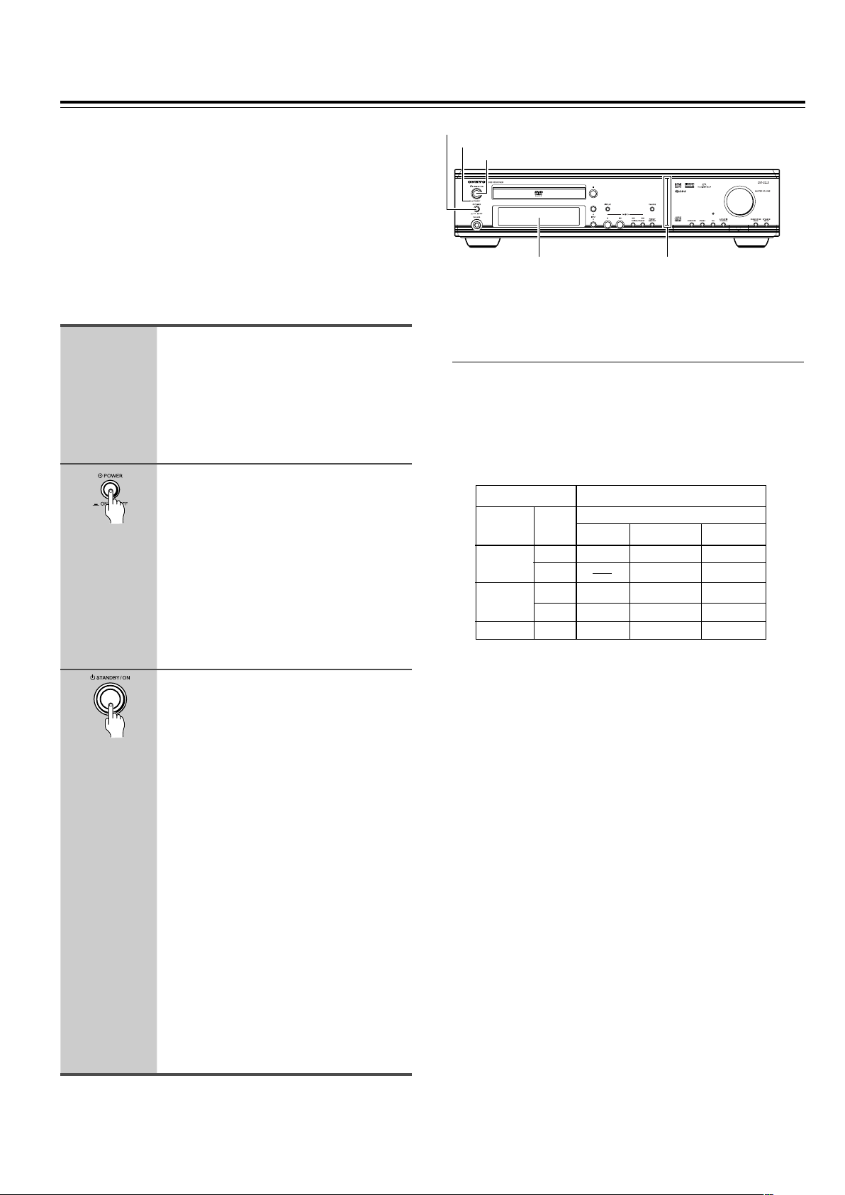
Connecting the Power/
STANDBY/ON
POWER
Turning on the DVD Receiver
Before connecting
• Make sure that all the connections from pages 15 to 25 are
complete (the connection to the TV is required).
• Turning on the DVD Receiver may cause a momentary power
surge, which might interfere with other electrical equipment such
as computers. If this happens, use a wall outlet on a different
circuit.
(European and some Asian models)
• The DVD Receiver is shipped with the main power (POWER)
switch in the on position (_ ON). When the power cord is
plugged in for the first time, the DVD Receiver will automatically
enter the standby state (same condition after step 2 below).
1
2
Connect the power cord to a wall
outlet.
(Other than European and some Asian
models)
The DVD Receiver enters the standby
mode and the STANDBY indicator lights
up.
(European and some Asian models
only)
Press POWER to switch on the
main power to put the DVD
Receiver in the standby mode.
The STANDBY indicator lights up.
• The buttons on the remote controller do
not operate if the POWER switch is set
to OFF.
• To switch off the main power, press
POWER again.
3
Press STANDBY/ON on the DVD
Receiver or ON on the remote
controller to turn on the DVD
Receiver.
The light and display on the DVD
Receiver’s front panel light. At the same
time, the STANDBY indicator goes off.
• To put the DVD Receiver in the standby
mode, press STANDBY/ON on the DVD
Receiver, or STANDBY on the remote
controller. Be sure to set the volume to
minimum before putting the DVD
Receiver in the standby mode for the
next use to avoid sudden loud sound
reproduction.
• While in the STANDBY mode, the DVD
Receiver can receive signals from the
remote controller. However, if you press
POWER on the DVD Receiver to switch
off the main power, the remote
controller cannot be used to turn on the
DVD Receiver.
• Setting the STANDBY button to standby
does not shut off the power completely.
(European and some Asian models only)
STANDBY indicator
Display Front panel
illumination
■ Setting the TV System (Other than North
American model)
The default setting of the DVD Receiver is AUTO, and unless you
notice that the picture is distorted when playing some discs, you
should leave it set to AUTO.
If you experience picture distortion with some discs, set the TV
system to match your country or region’s system. Doing this,
however, may restrict the kinds of disc you can watch. The table
below shows what kinds of disc are compatible with each setting
(AUTO, PAL and NTSC).
Disc Output format
Type
DVD
Video CD
CD, No disc
1 Switch the DVD Receiver into standby.
2 Hold down ¢ then press STANDBY/ON until the display
indicates the new setting to switch the TV system.
The TV system changes as follows:
AUTO = NTSC
NTSC = PA L
PAL = AUTO
Note that you have to switch the player into standby before each
change.
About MOD. (Modulation) PAL
• SHRINK
Most models of the newly developed countdown PAL TV system
detect 50 Hz (PAL)/60 Hz (NTSC) and automatically switch
vertical amplitude, resulting in a display without vertical
shrinkage.
• If your PAL TV does not have a V-Hold control, you may not be
able to view NTSC disc because the picture may roll. If the TV
has a V-Hold control, adjust it until the picture stops rolling. On
some TVs, the picture may shrink vertically, leaving black bands
at the top and bottom of the screen. This is not a malfunction; it is
caused by the NTSC = PAL conversion.
Format
NTSC
PAL
NTSC
PAL
Position of TV SYSTEM mode
NTSC PAL AUTO
NTSC MOD. PAL NTSC
PAL PAL
NTSC MOD. PAL NTSC
NTSC PAL PAL
NTSC PAL NTSC or PAL
2626
Page 27
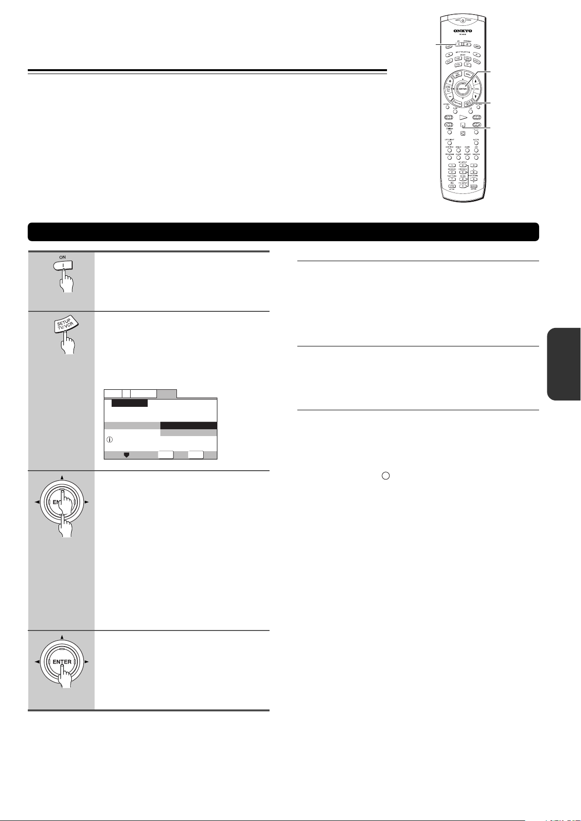
Setting Up the DVD Receiver
The Setup Navigator has been designed to simplify the
process of getting the DVD Receiver ready to perform.
Designed as a series of on-screen multiple-choice questions,
the Setup Navigator automatically sets the video, and
language settings according to how the questions are
answered. Once this procedure is complete, it will be possible
to begin using the DVD Receiver to enjoy DVDs.
The procedure on this page describes the operations
necessary to function within the Setup Navigator screens. A
detailed description of the contents of each question that
appears on the screen can be found on the following pages.
Using the Setup Navigator
ON
2/3/5/∞
ENTER
SETUP
7
1
2
3
Press ON (STANDBY/ON on the
front panel).
If there’s already a disc loaded and it starts
to play, press 7 to stop it.
Press SETUP.
When SETUP is pressed for the first time,
the following screen appears. Though the
Setup Navigator may be used more than
once, this screen only appears the first
time SETUP is pressed.
V2
Language
Move
General
Start
Auto Start Off
ENTER
Select
SETUP
Exit
Video1
Setup Navigator
Setup Navigator
Setup using the Setup Navigator
Use the cursor buttons (5/∞) to
make a selection.
• If you are going to use the Setup
Navigator, it is not necessary to change
the setting on the first screen. Please
proceed to the next step.
• If you do not want to set up the DVD
Receiver using the Setup Navigator,
use the cursor button (∞) to select [Auto
Start Off] at this time.
The Setup Navigator function may still
be used at a later time in manual Setup
screen menu operation (page 64).
■ When setting up for the first time
Some DVDs start playing automatically when loaded in the
DVD Receiver. Because the Setup Navigator cannot be used
if a disc is playing, it is recommended to set up the DVD
Receiver using the Setup Navigator before loading a DVD for
the first time. If a DVD has been loaded, be sure to press 7
before proceeding.
■ To change the answer to a prior question
Use the cursor button (2) to return to previous screens.
Please note, however, that you cannot go forward using the
cursor button (3), so it will be necessary to answer all the
questions that occur after the screen that was returned to.
■ To exit the Setup Navigator
Press SETUP while on any of the screens to exit the Setup
Navigator. Please note that if the Setup Navigator is exited
before all the questions are answered, no settings are
changed.
Note
On-screen information (i) appears to clarify the functions and
explain the options available.
4
Press ENTER.
The selection is entered and the next
Setup Navigator screen appears.
Use steps 3 and 4 as a basis for entering
selections on the all of the Setup Navigator
screens described on the following pages.
2727
Page 28
Setting Up the DVD Receiver
SETUP
ENTER
General
V2
Language
Video1
Exit
Move
Select
Changes are saved
Setup Navigator
Exit Setup Navigator
Save Changes
Delete Changes
Start Again
Using the Setup Navigator
■ Setting the OSD Language
(On-Screen Display Language)
The [OSD Language] screen establishes the OSD language,
or on-screen display language, which refers to the language
that is used by the DVD Receiver in menus and on-screen
messages. Additionally, the language that is established at
this setting will also be used for the default audio and subtitle
language.
V2
Language
Video1
Setup Navigator
Language
OSD Language
Select the On Screen Language
Settings: English (Factory setting)
Asian models only
Notes
• The languages that can be selected may be different from those
shown above.
• In addition to setting the [OSD Language], the audio and subtitle
language are also set at this time. If you wish to change the
audio or subtitle language to a different language, make changes
in the Setup screen Language menu [Audio Language] and
[Subtitle Language] as needed (pages 71, 72).
General
English
français
Deutsch
Italiano
Español
Move
ENTER
Select
SETUP
Exit
français
Deutsch
Italiano
Español
English (Factory setting)
■ Confirming the settings
The [Exit Setup Navigator] is the final screen in the Setup
Navigator.
Settings: Save Changes (Factory setting)
Select to have the DVD Receiver make all of the
necessary video and language settings according
to your responses in the Setup Navigator.
Delete Changes
Select to exit the Setup Navigator without changing
any of the system settings.
Start Again
Select to return to the [OSD Language] screen of
the Setup Navigator and do the settings again.
■ To change other player settings in the Setup
screen menus
The procedure for changing the settings in the Setup screen
menus is described on page 64.
The [TV Type] screen establishes the size, or more
appropriately the width to height ration of your television or
monitor. The width-to-height ratio of conventional TVs is 4:3,
while the width-to-height ratio of wide screen and highdefinition TVs is 16:9. This width-to-height ratio is called the
aspect ratio.
Video1
Settings: Widescreen (16:9) (Factory setting)
Note
There are two screen formats that can be used to display
wide-screen format DVDs: letter box and pan & scan. When
[Standard (4:3)] is selected in the Setup Navigator, the letter box
screen format is automatically selected. To switch the preference to
the pan & scan format, make changes in the Setup screen Video 1
menu [TV Screen] setting (page 66).
2828
■ Setting the TV screen size
V2
Language
Setup Navigator
TV Connection
Widescreen TV
16:9 aspect raito
General
Widescreen(16:9)
TV Type
Standard(4:3)
Move
ENTER
Standard (4:3)
Select
SETUP
Exit
Page 29
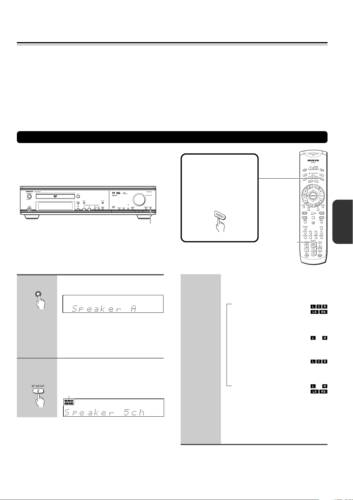
Speaker Setup
(North American and South American model)
You need to set up the speaker configuration for the speaker system connected to the FRONT SPEAKERS A connectors (see this
page.) (There is no speaker configuration setup for the FRONT SPEAKERS B system.)
(Other then North American and South American models)
You need to set up the speaker configuration for the speaker system connected to the SPEAKERS connectors (see page 30.)
Notes
• Speaker setup cannot be done if;
– Headphones are connected (see page 43), or
– The FRONT SPEAKERS B system is On (North American and South American model only, see page 42).
• It is not necessary to set the parameters again once you have completed the setup unless you change the speaker configuration.
Selecting the number of speaker channels (North American and South American model)
See following page for other than North American and South
American model.
Before operating the
remote controller
Press MODE AUDIO.
The remote controller
remains in the AUDIO mode,
until another MODE button is
pressed.
Unit only
1
SPEAKER
A / B
2
Remote controller
only
SPEAKER A/B
Press SPEAKER A/B to select
“Speaker A.”
Note
“Speaker B” also appears by pressing the
button repeatedly, though, this setting is
reserved for future applications. Therefore, be
sure to select “Speaker A.”
Press SP SETUP repeatedly to
select the number of channels for
the SPEAKERS A system.
Speaker configuration indicators indicate
current speaker configuration.
SP SETUP
Pressing the button repeatedly within three
seconds changes the number of channels
as follows (the corresponding speaker
configuration is described in parentheses):
→
Speaker 5
(Front left, center, and right,
plus surround left and right
speakers)
Speaker 2
(Front left and right speakers)
Speaker 3ch
(Front left, center, and right
speakers)
Speaker 4ch
(Front left and right, plus
surround left and right speakers)
ch
↓
ch
↓
↓
The normal display resumes in three
seconds.
Speaker configuration indicator at the
upper left corner shows the current
speaker configuration.
Notes
• The listening mode will automatically be set to “Stereo” (see
page 48) once you set or reset the number of channels.
• To check the present setting while the normal display is
displayed, press SPEAKER SETUP once. To change the setting,
press the button repeatedly within three seconds.
2929
Page 30
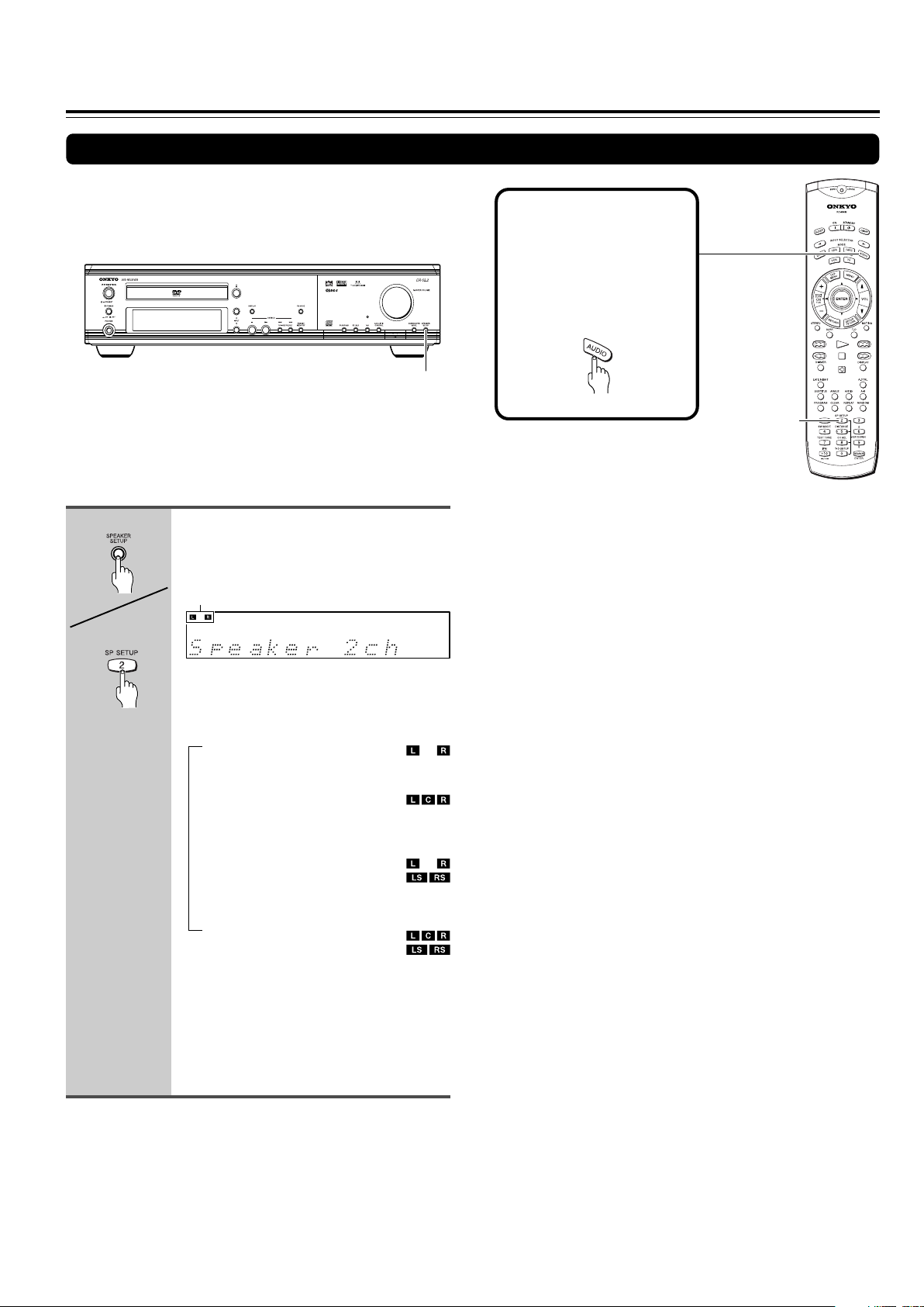
Speaker Setup
Selecting the number of speaker channels (other than North American and South American model)
Before operating the
remote controller
Press MODE AUDIO.
The remote controller
remains in the AUDIO mode,
until another MODE button is
pressed.
SPEAKER SETUP
SP SETUP
Unit
Remote controller
Press SPEAKER SETUP repeatedly
to select the number of channels
for the SPEAKERS system.
Speaker configuration indicators indicate
current speaker configuration,
Pressing the button repeatedly within three
seconds changes the number of channels
as follows (the corresponding speaker
configuration is described in parentheses):
→
Speaker 2
(Front left and right speakers)
Speaker 3
(Front left, center, and right
speakers)
Speaker 4ch
(Front left and right, plus
surround left and right speakers)
Speaker 5
(Front left, center, and right,
plus surround left and right
speakers)
ch
↓
ch
↓
↓
ch
Note
To check the present setting while the normal display is displayed,
press SPEAKER SETUP once. To change the setting, press the
button repeatedly within three seconds.
3030
The normal display resumes in three
seconds.
Speaker configuration indicator at the
upper left corner shows the current
speaker configuration.
Page 31

Selecting the Subwoofer mode
SUBWOOFER MODE
Before operating the
remote controller
Press MODE AUDIO.
The remote controller
remains in the AUDIO mode,
until another MODE button is
pressed.
SW MODE
Unit
Remote controller
Press SUBWOOFER MODE on the
unit or SW MODE on the remote
controller.
SW indicator lights up when SW Mode 1, SW
Mode 2 or SW Mode 3 is selected.
With the first press of the button, you can
check the present setting. Then each
press of the button changes the subwoofer
mode as follows (a tip on how to select the
right subwoofer mode is in parentheses):
→
SW Mode 1
(When small–with limited bass signal
handling–front speakers are
connected)
↓
SW Mode 2
(When large–wideband–front speakers
are connected)
↓
SW Mode 3
(When large–wideband speakers are
connected to all channel)
↓
SW Off
(When no subwoofer is connected)
The initial setting varies depending on the
area which it was purchased.
North American and South American
model: SW Mode 1
Other models: SW Mode 2
The normal display resumes in three
seconds.
3131
Page 32

DISTANCE
UP/DOWN 5/∞
Speaker Setup
Setting the Distance From the Listening Position to Each Speaker
Before starting the procedure below, measure the distances
from each speaker to the listening position.
For pair speakers such as front left and right speakers, the
distance from the listening position to one speaker should be
the same as the distance to the other.
In the procedure below, select the values which approximate
the actual distances.
1
Remote controller
only
2
3
«
Press DISTANCE.
The distance entry display for the front left
and right speakers appears.
Press UP/DOWN 5/∞ to select the
front left and right speaker
distance.
You can select a distance between 0.3 m
and 9 m (1 ft. and 30 ft.).
Press DISTANCE, then press
UP/DOWN 5/∞ repeatedly to select
the center speaker distance.
4
5
Press DISTANCE, then press
UP/DOWN 5/∞ repeatedly to select
the surround left and right speaker
distance.
«
You cannot enter the following distances:
• Distances longer than the distance set
for the front speakers.
• Distances shorter than the distance
obtained by subtracting “4.5 m (15 ft.)”
from the distance entered for the front
speakers.
Note
If you selected a speaker configuration with no
surround speakers on the previous page, this
step will be skipped.
Press DISTANCE.
The normal display resumes.
3232
You cannot enter the following distances:
• Distances longer than the distance set
for the front speakers.
• Distances shorter than the distance
obtained by subtracting “1.5 m (5 ft.)”
from the distance entered for the front
speakers.
Note
If you selected a speaker configuration with no
center speaker on the previous page, this step
will be skipped.
Page 33

Adjusting Each Speaker's Relative Volume Balance – Test Tone
CH SEL
TEST TONE
UP/DOWN 5/∞
Adjust each speaker’s relative volume balance so that the
volumes of all speakers’ test tones sound equal at the
listening position.
1
Remote controller
only
2
«
Press TEST TONE.
Each speaker emits the test tone (pink
noise) and the display shows the speaker
emitting the test tone in the following
order:
Left → Center
(Front left ch.) (Center ch.)
↑↓
Subwfr Right
(Subwoofer) (Front right ch.)
↑↓
Surr L ← Surr R
(Surround left ch.) (Surround right ch.)
Note
No test tone will be emitted from the speaker
which is not included in the speaker
configuration on pages 29-31 even if it is
actually connected.
Press CH SEL repeatedly to select
the speaker, then press UP/DOWN
5/∞ to adjust the volume level.
The volume level can be adjusted between
–12dB and +12dB.
3
When you have completed the
adjustment by repeating step 2,
press TEST TONE.
The test tone stops and the normal display
resumes.
Note
Even if you don’t press TEST TONE, the test
tone will stop after two minutes.
3333
Page 34

Getting Started Using Your
DVD Receiver
Before you can start to enjoy the digital audio and video
on DVDs, be sure that you have either performed the
Setup Navigator procedure described in the previous
section or made the necessary settings in the Setup
screen menus as outlined in the next section to set up
the player to correspond to your home system. Having
made these settings, you are now ready to start using
the player to enjoy DVDs, Video CDs, CDs and MP3s.
DVD
VCD
CD
MP3
Playing DVDs, Video CDs, CDs and MP3s
1
2
Press 0.
The disc tray comes out.
Load a disc.
Load a disc with the label side facing up,
using the disc tray guide to align the disc.
■ About the
DVD
VCD, CD
,
and
MP3
marks in
the pages related to disc operation
DVD
means the function or title is related to DVD-Video operation.
VCD
means the function or title is related to Video CD operation.
CD
means the function or title is related to audio CD operation.
MP3
means the function or title is related to MP3 operation.
4
Select the item you want to view.
• When a DVD is loaded:
Select the item with the cursor buttons
(2/3/5/∞) or the number buttons then
press ENTER.
• When a Video CD is loaded:
Use the number buttons to select the
item.
3
Press £.
• The disc tray closes, and playback
begins.
• MP3 only: It may take a few seconds for
the DVD Receiver to locate the track on
the disc, depending on the complexity
of the file structure.
• Depending on the disc, a menu may be
displayed. If a menu is displayed,
proceed to step 4.
• To pause playback, press
playback, press
Inserted disc indicator (DVD, CD, VCD)
or £.
Pause indicator
Play indicator
. To resume
Notes
• The TV screen size is factory set to present the wide screen
format (16:9 aspect ratio). If you have a standard TV screen (4:3
aspect ratio), this setting can be changed to match your TV
screen size in the Video 1 menu (pages 28, 66).
• Do not move the DVD Receiver during playback. Doing so may
damage the disc.
• Use 0 on the DVD Receiver to open and close the disc tray. Do
not touch the disc tray while it is moving. Doing so may cause the
DVD Receiver to malfunction.
• Do not press down on the disc tray or put any objects other than
playable discs on the disc tray. Doing so may cause the DVD
Receiver to malfunction.
• In many instances, a menu screen appears when playback of a
movie is complete. Prolonged display of an on-screen menu may
damage your television set, permanently etching that image onto
its screen. To avoid this, be sure to press 7 once the movie is
complete.
■ When an operation is prohibited
There are times when you are using the DVD Receiver and
attempt to perform an operation, but for some reason it cannot
be performed. When this occurs, one of the two following
icons appears on the screen.
The operation is prohibited by the DVD Receiver.
The operation is prohibited by the programming on the
disc.
34
Page 35

TOP MENU
MENU
2/3/5/∞
ENTER
Disc tray
£0
DVD
VCD
When a Menu Screen is Displayed
Menu screens are displayed for DVDs that have menu
screens or Video CDs that include Playback Control (PBC).
DVDs often contain extra information that can be accessed in
the DVD menu and sometimes makes navigating DVD menu
screens as enjoyable as watching the feature presentation.
Example: When a DVD that has menu screens is loaded
1 Highlight Clips
2 Chapter List
3 Commercial Header
4 Subtitles
5 Soundtrack
6 Start Main Feature
Example: When a Video CD that has Playback Control is
loaded
STANDARD VOCAL BEST
1
Don't Tekno for an Answer
2
Bad Whack Naff Riff
3
dubmyheadbassman
4
Gooey Love Jingle
5
Praise the Day
6
G3, Ba-san
7
Abstract Jazz Phunk
8
Rock the Love Jive
Bertie B.& the Goans
Hood in the Boyz
Sleek Machine
Philip William
Formerly an Artist
Pfeuti
John Torn
Hot Monkey Stick
RETURN
£
¢4
7
Number
buttons
DVD
VCD
To Open or Return To the DVD or Video
CD Menu Screen
Although this differs depending on the disc, pressing MENU,
TOP MENU, or RETURN during DVD playback or RETURN
during Video CD playback displays the menu screen. Refer to
the DVD or Video CD disc jacket and accompanying
documentation for more information.
■ To play Video CDs without displaying menu
screens
Video CDs with Playback Control (PBC) display a menu
screen when play is started. It is possible, however, to play
back Video CDs without displaying menu screens.
When a Video CD with PBC is loaded, press 7, and then the
number button of the track you want to play.
■ To navigate a menu screen
• Although individual DVD titles may differ, when a menu
screen is displayed, use the cursor buttons (2/3/5/∞) and
ENTER on the remote control. The cursor buttons are used
to move around the options on the screen and ENTER is
used for selection.
• Occasionally, the number buttons may also be used to
make selections. If this is possible, using number buttons
serves to directly select an option on a menu screen. Only
number buttons are used to make selections on Video CD
menu screens.
• When the Video CD has more than one menu, pages can
be advanced to or returned to with 4 or ¢.
35
Page 36

Getting Started Using Your DVD Receiver
DVD
VCD
CD
MP3
Chapter (Track) Skip Forward/Skip
Back
Remote controller
Unit
Advancing to the next chapter (track)
Press ¢.
Press to skip forward to the next chapter
(track).
Skipping back to the previous chapter
(track)
Press 4.
• Press once to skip back to the start of
the chapter (track) currently playing.
• Press twice to skip back to the start of
the previous chapter (track).
DVD
VCD
CD
MP3
Forward and Reverse Scanning
Remote controller
Unit
Fast forward and reverse scanning
Press and hold 1/¡ (4/¢ on
the front panel) during playback to
scan forwards or backwards.
While “¡1” or “1 1” is displayed onscreen blinking, release the button to
resume normal playback.
Variable speed scanning (Remote
controller only)
1 Press (but don’t hold) ¡ or 1
during playback to start scanning.
“¡ 1” or “1 1” appears on screen.
2 Depending on the type of disc
playing, you can increase the
scanning speed by pressing ¡
or 1.
The scan speed is shown on-screen.
DVDs have three scanning speeds;
1 ↔ 2 ↔ 3
CD and Video CDs have two scanning
speeds;
1 ↔ 2
MP3 have only one scanning speed.
3 Press £ to resume normal
playback.
36
Page 37

STANDBY/ON
7
TUNING/PRESET 4/¢
£
1
£
STANDBY
¢4
¡
7
DVD
VCD
Resuming playback from where you
stopped
Use the resume feature to restart playback from the point that
the disc was stopped last time.
This features cannot be used with MP3s and CDs.
1
Remote controller
Unit
2
Remote controller
Press 7 once.
The display shows “STOP” then
“RESUME”, and the stop position is
memorized.
• The resume position remains
memorized as long as the disc is in the
DVD Receiver — even if you switch the
power off.
• Pressing 7 twice causes the disc to
return to the beginning when £ is
pressed again. The display shows the
disc type (DVDs or Video CDs).
Press £.
Playback starts from the resume position.
DVD
VCD
CD
MP3
Stopping Playback and Switching
Power Off
1
Remote controller
Unit
2
3
Press 7.
Playback stops.
Press 0.
The disc tray comes out.
Remove the disc.
Unit
Notes
• The actual restart position may be slightly before or after the
resume position.
• The memorized resume position is erased when you open the
disc tray, or change the Parental Lock Level setting (page 75) or
On-screen Display (OSD) setting (page 70).
4
Remote controller
Unit
Press STANDBY/ON (STANDBY on
the remote controller).
The disc tray goes back in.
37
Page 38

Listening to the Radio
PRESET MEMORY
FM MODE
INPUT 5/∞
TUNING/PRESET 4/¢
There are two ways to select radio stations:
• Manual tuning
• Presetting radio stations then selecting the preset
channels
Tuning Manually
1
2
Unit
Unit only
Press INPUT 5/∞ repeatedly to
select the band (FM or AM).
e.g. When FM is selected.
Note
You can also select the band with the remote
controller. See next page.
Press and hold TUNING/PRESET
4/¢ for about 0.5 seconds.
• When the band is FM
Auto tuning starts. The frequency
changes in 50 kHz steps.
When a broadcast is received, scanning
stops and the frequency flashes in the
display.
• When the band is AM
The frequency changes as follows:
– (North American and South American
models)
In 10 kHz steps
– (Other models)
In 9 kHz steps
When you release the button, the frequency
stops changing and flashes in the display.
Appears when a broadcast is received.
Tuning in a weak frequency (only for FM stations)
When you tune in a stereo FM station, the FM ST indicator lights up
if the signal is sufficiently strong.
If the signal is weak, you may not be able to tune to the station.
In this case, press FM MODE. The FM ST indicator and AUTO goes
off. Then select the station to which you want to listen.
(At this time, the station will be in mono and interstation noise will be
heard.)
Unit Only
Presetting Radio Stations
You can preset up to 30 stations.
1
2
Unit only
Tune in the radio station you wish
to preset (see steps in the left
column of this page).
Press PRESET MEMORY.
The MEMORY indicator lights and the
preset number starts flashing in the
display.
38
3
While the frequency is flashing (for
about 5 seconds), press TUNING/
PRESET 4/¢ to change the
frequency.
• The frequency changes each time you
press TUNING/PRESET 4/¢.
• You can change the frequency as long
as the frequency in the display is
flashing. Each press of either button
causes the frequency to flash for about
5 seconds.
3
4
While the MEMORY indicator is lit
(for about 8 seconds), press
TUNING/PRESET 4/¢ to select
the preset number.
Press PRESET MEMORY.
The radio station is registered to the
preset channel.
To register another preset station, repeat
steps 1 to 4.
Page 39

PRESET MEMORY
INPUT SELECTOR 2/3
CH +/–
Selecting Preset Stations
Before selecting preset stations, you need to preset the radio
stations. See “Presetting Radio Stations” on the previous
page.
Remote
1
controller
Press INPUT SELECTOR 2/3 on
the remote controller or INPUT 5/∞
on the unit to switch the input
source to the FM or AM.
The band selected in this step will not
affect the next step.
Press CH +/– on the remote
controller or TUNING/PRESET
4/¢ on the unit repeatedly to
select the preset number of the
desired radio station.
2
Unit
Remote
controller
INPUT 5/∞
TUNING/PRESET 4/¢
Erasing a Preset Station
1
Unit only
2
3
Select the preset channel you wish
to erase (see steps in the left
column of this page).
Press PRESET MEMORY.
“Erase?” appears in the display.
While “Erase?” is displayed (for
about 8 seconds), press PRESET
MEMORY again.
The selected preset channel will be
erased.
Receiving RDS (European models
only)
When an RDS (Radio Data System) station broadcasting PS
(Program Service Name) information is received, the RDS
indicator lights up and the name of the station is displayed.
(RDS reception is only available in areas where RDS
broadcasts are available.)
Unit
Notes
• If you press TUNING/PRESET 4/¢
on the unit for more than 0.5 seconds,
the unit enters the manual tuning mode.
See step 2 in “Tuning Manually” on the
previous page.
• If you press MODE TV before pressing
CH +/–, the remote controller doesn’t
operate (see page 15).
In this case, press another MODE
button such as MODE AUDIO.
Various Functions While Listening to
Radio Programs
To use the following functions, see page 42.
• Turning on/off the SPEAKERS A/SPEAKERS B Systems
(North American and South American models only)
• Adjusting the Volume
• Muting the Sound
• Listening Through Headphones
• Controlling the Brightness of the display on the DVD Receiver
• Using the Sleep Timer
Enjoying the Sound Effects While
Listening to Radio Programs
See page 44.
39
Page 40

Playing the Connected Source
This section shows you how to play the
sources connected to the DVD Receiver.
You may need to see “Connecting to a TV”
on pages 16, 17 and “Connecting to Audio/
Video Equipment” on pages 21 and 22 while
following the steps in this section.
INPUT 5/∞
INPUT SELECTOR 2/3
1
2
Remote
controller
Unit
Press INPUT SELECTOR 2/3 on
the remote controller or INPUT 5/∞
on the unit to select one of the
following input sources:
• VIDEO 1
• VIDEO 2/CDR/PC
• TV/LINE
• TAPE/MD/HD
The selected input source appears in the
multipurpose display. Also the input
source indicator is lit in the display until
the DVD Receiver is switched to another
input source.
e.g. When VIDEO 1 is selected.
Start playing the selected source.
About digital sound
If the equipment is digitally connected to the DVD Receiver,
the sound from the digital input will automatically be selected
and reproduced instead of the analog sound as explained
below.
• When the VIDEO 1 source is selected, the digital sound
from the DIGITAL INPUT VIDEO 1 COAX jack is
reproduced.
• When the VIDEO 2 source is selected, the digital sound
from the DIGITAL INPUT VIDEO 2 OPT jack is reproduced.
When the digital sound is reproduced, the DIGITAL indicator
lights up in the display. According to the received sound
system, the ŸDIGITAL or DTS indicator lights up.
ŸDIGITAL DTS DIGITAL
Note
The DVD Receiver only reproduces DOLBY DIGITAL, DTS, and
PCM sound formats from connected equipment.
Enjoying the picture with the sound of
another source
40
Play the VIDEO 2 source and select TV/LINE, TAPE/MD/HD,
FM or AM. Then you can enjoy the VIDEO 2 picture and the
sound from the selected input source at the same time.
Various Functions While Playing the
Connected Source
To use the following functions, see page 42.
• Turning on/off the SPEAKERS A/SPEAKERS B Systems
(North American and South American models only)
• Adjusting the Volume
• Muting the Sound
• Listening Through Headphones
• Controlling the Brightness of the display on the DVD Receiver
• Using the Sleep Timer
Enjoying the Sound Effects While
Playing the Connected Source
See page 44.
Page 41

Operating the Onkyo MD Recorder/CD Recorder/Cassette Tape Deck/Hard Disk
Recorder With the Supplied Remote Controller
Operating the Onkyo CD recorder, MD recorder, cassette tape deck or hard disk recorder to the
DVD Receiver with the z cable (see page 23)
Point the remote controller toward the DVD Receiver when you want to operate this equipment.
Press MODE TAPE/
Press MODE CDR
first.
CD recorder
ON On/Standby
STANDBY Standby/On
£ Play
7 Stop/Cancel
Pause
4 Down
¢ Up
1 Fast Reverse
¡ Fast Forward
REPEAT Repeat mode
RANDOM Random play
DISPLAY Change display
PROGRAM Program
CLEAR Clear
0–9, +10 (--/---) Number buttons
ON
MODE
CDR
4
1
7
STANDBY
MODE
TAPE/MD/HD
£
¢
¡
DISPLAY
MD/HD first.
The initial setting for input is TAPE.
Holding MODE TAPE/MD/HD for
about 2 seconds switches the input
setting as follows: TAPE → MD,
MD → HD, HD → TAPE
MD recorder
ON On/Standby
STANDBY Standby/On
£ Play
7 Stop/Cancel
Pause
4 Down
¢ Up
1 Fast Reverse
¡ Fast Forward
REPEAT Repeat mode
RANDOM Random play
DISPLAY Change display
PROGRAM Program
CLEAR Clear
0–9, +10 (--/---) Number buttons
Notes
• You can use graied buttons in the
illustration to control the DVD Receiver in
any mode.
• Some buttons may not work properly.
PROGRAM
CLEAR
RANDOM
REPEAT
Number
buttons
Cassette tape deck
£ Play
7 Stop
Reverse play (Reverse tape
deck only)
4 Rewind
¢ Fast forward
Hard Disk Recorder
ON On
STANDBY Standby
£ Play/Pause
7 Stop/Cancel
4 Down
¢ Up
REPEAT Repeat mode
RANDOM Random play
DISPLAY Change display
0–9, +10 (--/---) Number buttons
41
Page 42

Various Functions Common to all the Sources
Turning on/off the SPEAKERS A/
SPEAKERS B Systems (North
American and South American models
only)
You can turn on or off the speaker systems connected to the
FRONT SPEAKERS A and B connectors individually.
Note
When you select “SPEAKER A+B”, the SPEAKER A system
reproduces stereo sound automatically. (The listening mode is set to
“Stereo.”)
When you select “SPEAKER A”, the listening mode returns to the
previous mode.
Operating with the unit
SPEAKER
A / B
Press SPEAKER A/B repeatedly.
Each press of the button changes the On/Off
mode as follows:
→
Only the SPEAKERS A system turns on.
↓
Only the SPEAKERS B system turns on.
↓
Both the SPEAKERS A and B systems
turn on.
Adjusting the Volume
The volume of the front left and right, center, surround left
and right, and subwoofer speakers will be adjusted at the
same time.
When headphones are connected (see next page), you can
adjust the volume of the sound through the headphones.
Operating with the remote controller
Press VOL 5/∞.
Operating with the unit
Turn MASTER VOLUME clockwise
to increase the volume, or
counterclockwise (anticlockwise)
to decrease the volume.
42
Muting the Sound
Remote
controller only
Tip
If you turn off the unit during muting, and turn it on again, the sound
will be restored.
Press MUTING.
“Muting” appears in the multipurpose display
for about three seconds. Also the MUTING
indicator flashes in the display during the
muting mode.
To restore the sound, press MUTING again.
Page 43

SLEEP
DIMMER
VOL 5/∞
MUTING
PHONES jack
MASTER VOLUME
Listening Through Headphones
Connect the plug of the stereo headphones to the
PHONES jack on the DVD Receiver.
Notes
• The speakers will not reproduce sound while headphones are
connected.
• The listening mode is set to “Stereo” after connecting the
headphones to the PHONES jack.
• When you disconnect the headphones, the listening mode returns
to the previous mode.
SPEAKER A/B
(North American and South
American
models only)
Using the Sleep Timer
Remote
controller only
Checking the remaining time
Press SLEEP while the Sleep Timer is On.
If you press SLEEP while the remaining time is displayed,
the remaining time is reduced by 10 minutes.
Press SLEEP.
“Sleep 90min” appears in the multipurpose
display for about 5 seconds, which means the
DVD Receiver will turn off and enter standby
mode in 90 minutes. Also the SLEEP
indicator is lit in the display while the sleep
timer is On.
Each press of the button makes the
remaining time shorter by 10 minutes.
Controlling the Brightness of the
display on the DVD Receiver
Remote
controller only
Press DIMMER.
Each press of the button changes the
brightness as follows:
The display becomes less bright.
→
↓
The display is dimmed.
↓
The display is dimmed, and
panel illumination goes off.
↓
The display resumes the original
brightness and
illumination turns on.
the front panel
Canceling the Sleep Timer
Press SLEEP repeatedly until the SLEEP indicator goes
off.
the front
43
Page 44

Enjoying the Sound Effects
The surround sound of the DVD Receiver enables you to enjoy the presence of a movie theater or concert hall in your room.
Before using any sound effect, make sure the Speaker Setup configurations have been set (see pages 29-33).
The speaker configuration is very important for the surround sound. See “Connecting Speakers” on pages 18, 19 and “Positioning
Speakers” on page 20.
Following are the sound systems the DVD Receiver can reproduce.
DOLBY DIGITAL Surround and DTS (Digital
Theater System) Surround
Recommended speaker setup
Center Speaker
Left front speaker
Subwoofer
This 5.1 channel digital surround format enables you to
individually play five full-range (20Hz–20kHz) channels (left
and right front, center, and two surround channels) plus an
LFE (Low Frequency Effect) channel for the low-range effect
sound. It will create a realistic sound like that heard in
theaters and concert halls.
DOLBY DIGITAL Surround
DVD videos that have the mark are recorded using
this system.
To playback DOLBY DIGITAL Surround sound from
connected equipment, you must make the digital connection
in addition to the above speaker configuration.
DTS Surround
DVD videos and audio CDs that have the mark are
recorded using this system.
To playback DTS Surround sound from connected equipment
such as an LD player, you must make the digital connection
in addition to the above speaker configuration.
Notes on DTS Surround
• If you play a DTS Surround encoded disc with the DVD Receiver,
or a DTS encoded disc using a digitally connected player, you may
hear a noise for a short while until the DTS decoder of the DVD
Receiver recognizes the DTS encoded signal and starts operating.
This is not a malfunction.
• If you play a DTS Surround source in fast reverse or fast forward,
pause, or skip a chapter or track, noise may be heard. This is not
a malfunction.
• Even when playback of the DTS Surround source stops and the
DTS signal transmission ends, the DVD Receiver remains in DTS
mode and the DTS indicator remains lit. This is to prevent noise
when you pause, fast forward, fast reverse, or skip a chapter or
track of the playback source. Therefore, if the source switches
from the DTS signal to a PCM (2 channel digital stereo) signal
immediately, the PCM signal may not be played. In such a case,
stop playback for about three seconds, then resume playback.
• Some CD players (if connected to the DVD Receiver) and LD
players may be unable to play DTS Surround sources correctly
even if you connect the player to the DVD Receiver digitally. In
such a case, the digital signals (such as the output level, sampling
frequency, frequency response, etc.) processed by the DVD
Receiver cannot be recognized as DTS data by the DVD Receiver
and you may hear noise instead of the proper sound.
Right front speaker
Right surround speakerLeft surround speaker
DOLBY PRO LOGIC II Surround
This is a 5-channel surround system of a new generation,
casting a bridge between the previous 4-channel (Left/Right
Front, Center and monaural surround channels) Pro Logic
surround and 5.1-channel Dolby Digital surround. Dolby Pro
Logic II provides the Movie mode optimized for viewing
movies and the Music mode optimized for listening to music.
In the Movie mode, the surround channel, which has been
monaural and based on narrow band, is reproduced in stereo
so that the feeling of movement in the played movies is more
enhanced. In the Music mode, the surround channel
reproduces natural sound field even with 2-channel music
sources.
The Movie mode allows you to enjoy VHS and DVD software
carrying the
broadcast programs. The Music mode allows you to enjoy
stereo music from CD, etc.
marking as well as some of TV
Onkyo’s original Digital Signal Processing
(DSP) modes
The DVD Receiver offers the following special Onkyo sound
effects for sources other than Dolby Digital and DTS sounds.
Orchestra
This mode is suitable for classical and opera music. The
center channel is cut and the surround channels are
emphasized to widen the stereo image. It simulates a natural
reverberation as created in a large hall.
Unplugged
This mode is suitable for acoustic instrumental sounds,
vocals, and jazz music. By emphasizing the front stereo
image, it simulates the acoustics in front of the stage.
Studio-Mix
This mode is suitable for rock and popular music. Lively
sounds with a powerful acoustic image will make you feel as
if you are in a club.
TV Logic
This mode offers the realistic acoustics of a TV program
being aired in the TV studio. It enhances the entire surround
sound and clarity of conversation.
All Ch St (All Channel Stereo)
This mode is useful for background music. The front and
surround channels will create a stereo image.
44
Page 45

Theater-Dimensional (T-D)* mode
The ideal home theater is realized by the multichannel sound
reproduction with the complete speaker configuration and
speaker positioning described on page 20. However,
sometimes it is difficult to meet all those conditions. In reality,
you may only have front speakers, or not be able to place the
surround speakers in position.
Even if your speaker system is not complete, you can enjoy
the multichannel surround sound by using the TheaterDimensional mode. Theater-Dimensional mode sets the
output channels to generate the most suitable virtual
surround reproduction according to the number of the
speaker channels set in “Speaker Setup” on page 29 or 31.
The importance of the speaker setup
Calibrating each speaker’s sound pressure is essential for
home theater sound reproduction. The same thing can be
said for virtual surround sound reproduction. Especially level
matching and the time alignment of the two speakers that
reproduce virtual surround signals becomes an even more
important factor than with normal multichannel reproduction.
For the DVD Receiver, the calibration for the multichannel
reproduction (see speaker distance setting on page 32 and
test tone adjustment on page 33) provides the most
appropriate level matching.
Notes
• For the input sources which include the surround channel signals
like the multichannel DOLBY DIGITAL and DTS surround sounds,
the virtual processing is applied to those surround channel signals.
• For the 2 channel input sources, the surround channel elements
are automatically extracted with the DOLBY PRO LOGIC
processing before the virtual processing is applied.
• For the monaural or front 3 channel stereo sources, the virtual
surround effect does not work since those input sources do not
include the surround channel signals.
* Theater-Dimensional is a virtual surround technology developed
by Onkyo. This technology is approved by Dolby Laboratories for
the virtual surround processing of the Virtual Dolby Digital and
Virtual Dolby Surround products.
The Input Sources and Available
Listening Modes
The available listening modes varies depending on the
sound type of the input source. The table below shows the
correlation between the input source types and listening
modes.
(× marked listening modes can be chosen with a particular
type of a source.)
Input Source Signals
Possible
sources
Listening
Modes
Stereo ×××
Theater-Dimensional ×××
DOLBY DIGITAL ×
DTS ×
PL II Movie/PL II Music ××*
Orchestra ×
Unplugged ×
Studio-Mix ×
TV Logic ×
All Ch Stereo ×
* PL II Movie/Music can be selected only when the source is
2-channel.
Note
The listening mode is set to “Stereo” when the PCM sound whose
sampling frequency is higher than 48kHz is played. Such highresolution sounds are reproduced from sources such as DVD video.
Analog/PCM Dolby Digital DTS
Audio cassette,
audio CD,
VIDEO CD,
Record,
FM broadcast,
AM broadcast
DVD video,
LD,
Digital
(satellite)
broadcast
DVD video,
audio CD,
LD
Checking the Sound System of the
Playing Source
The DVD Receiver will automatically detect the sound
system when DOLBY DIGITAL Surround (
Surround (
), or PCM/MP3 DIGITAL (2 channel digital
stereo) is played back. The corresponding sound system
indicator lights in the DVD Receiver’s display.
), DTS
DOLBY DIGITAL DTS DIGITAL (PCM/MP3)
45
Page 46

Enjoying the Sound Effects
Choosing Theater-Dimensional Mode
Theater-Dimensional mode is the technology which controls the characteristics of the sounds reaching the listener’s left and right
ears, therefore, there is a sweet spot where you can best experience the Theater-Dimensional effects. You need to adjust the
location of the sweet spot and these other factors for the best possible Theater-Dimensional effect.
Listening angle
(“Lisng. Angle” appears in the
display.)
Left speaker
L
The longer the distance
between the two speakers is,
the wider the angle is.
L
Listening
angle
40°
20°
R
Right speaker
R
Virtual Surround Level
(“V. Surr Level” appears in the
display.)
The listening angle is the angle at the listening position where the two lines from the left and
right speakers meet.
You need to adjust the listening angle in the following cases:
• If you set “Speaker 2ch” or “Speaker 3ch” in “Speaker Setup” on pages 29 and 30.
Consider the listening angle as being formed from the left and right
front speakers since the
virtual surround signals are output from the front speakers.
• If you cannot place the surround speakers in the correct position.
– Place each surround speaker on top of or on the outer side of each front speaker of the
same side.
– Consider the listening angle as being formed from the left and right
surround speakers since
the virtual surround signals are output from the surround speakers.
Set “Lisng. Angle” to one of the following settings, which you feel is most effective (the
listening angles in parentheses are the ideal degrees):
• Normal (30°)
• Wide (40°)
• Narrow (20°)
This parameter adjusts the virtual surround level.
Set “V. Surr Level” to one of the following 7 values, which you feel is most effective:
–3, –2, –1, 0, 1, 2, and, 3
Dialog mode
(“Dialog Mode” appears in the
display.)
The dialog in the film may sound less clear because of the music or other sounds depending on
the movie or scene.
In such a case, set “Normal” to “Enhance.” (The factory setting is “Normal” which is the normal
mode.)
Notes
• This function emphasizes the dialog in the center channel since the dialog sound, in most films, is
allocated to the center channel. Therefore, if the dialog is not in the center channel, the sound will not be
enhanced.
• Depending on the type of source, this mode is not very effective.
46
Page 47

Activating Theater-Dimensional mode
See “The Input Sources and Available Listening Modes” on
page 45.
T-D
T-D
(Indicator and button)
Adjusting Theater-Dimensional mode
Press MODE AUDIO first.
T-D SETUP
UP/DOWN 5/∞
Remote controller
Unit
Notes
• Theater-Dimensional mode cannot be activated if;
– Headphones are connected,
– SPEAKERS B system is On (North American and South American
models only), or
– The source is PCM sound with a sampling frequency higher than
48kHz.
• Theater-Dimensional mode will be canceled and the T-D indicator
goes off when:
– Another listening mode is chosen, or
– The input source is switched to a type of source which Theater-
Dimensional mode cannot process.
Press T-D.
“Theater-Dimensional” scrolls across in
the display and the Theater-Dimensional
indicator on the unit lights.
1
2
Remote controller
only
3
Activate Theater-Dimensional (see
the steps in the left column of this
page).
Press T-D SETUP repeatedly to
select the Theater-Dimensional
item (see on the previous page).
Each press of the button changes the item
as follows:
→
Lisng. Angle
↓
V. Surr Level
↓
Dialog Mode
↓
The normal display resumes.
Press UP/DOWN 5/∞ to select the
setting of the item.
• To change the setting of another item,
repeat steps 2 and 3.
• To end the Theater-Dimensional setup,
press T-D SETUP repeatedly until the
normal display resumes.
47
Page 48

Enjoying the Sound Effects
Using Dolby Pro Logic II/
Onkyo’s Original DSP Modes
See “The Input Sources and Available Listening Modes” on
page 45.
SURR
SURROUND
Remote controller
Unit
Press SURR on the remote
controller or SURROUND on the
unit to choose “PL II” or the DSP
mode.
The current listening mode appears in the
display when the button is pressed once,
then each press of the button changes the
listening mode as follows:
DSP indicator
Changing the Sound to Stereo
See “The Input Sources and Available Listening Modes” on
page 45.
STEREO
STEREO
Remote controller
Unit
Press STEREO.
In the display, “Stereo” appears and the
STEREO indicator lights up.
PL II Movie → PL II Music
↑↓
All Ch St Orchestra
↑↓
TV Logic Unplugged
↑↓
Studio-Mix
• In the display, “PL II Movie” or “PL II Music”
appears and the Ÿ PRO LOGIC II indicator
lights up.
• PL II and DSP mode cannot be selected
when “Speaker 2ch” is selected. (Only
“Stereo” can be selected.)
• Only “PL II Movie” or “PL II Music” can be
selected when “Speaker 3ch” is selected.
48
Page 49

Adjusting Each Speaker’s Relative Volume Balance Temporarily
You can readjust each speaker’s relative volume balance
according to your preference while listening to the sound.
The adjusted values will return to the values set on page 33
when the DVD Receiver enters standby mode, or the main
power is switched off unless you save the values.
Press MODE AUDIO first.
CH SEL
TEST TONE
UP/DOWN 5/∞
Remote controller
only
(Checking each speaker’s relative
volume balance)
While playing the source, press CH
SEL repeatedly.
Each press of the button changes the
speaker which outputs the sound and the
selected speaker appears in the display in
the following order:
Left (Front left ch.)
↓
Center (Center ch.)
↓
Right (Front right ch.)
↓
Surr R (Surround right ch.)
↓
Surr L (Surround left ch.)
↓
Subwfr (Subwoofer)
↓
Speaker volume adjustment mode off
21
(Adjusting each speaker’s relative
volume balance)
Press CH SEL repeatedly to select
the speaker, then press UP/DOWN
5/∞ to adjust the volume level.
The volume level can be adjusted
between –12dB and +12dB.
Repeat this step to change another
speaker’s volume balance.
Saving the adjusted values
Remote controller
only
Press TEST TONE.
Note
Any speaker that is not included in the speaker
configuration on pages 29-31 is not selected
even if it is actually connected.
49
Page 50

Enjoying the Sound Effects
Using the LATE NIGHT/FRONT EFFECT
Function
• The LATE NIGHT function operates when the sound is
DOLBY DIGITAL Surround.
If you play a movie at low volume at night, set this function
to “Low” or “High” to narrow the dynamic range of the
sound and make it easier to hear.
• The FRONT EFFECT function operates with DSP
modes other than All Ch St.
If you use one of the DSP sound effects with a source
containing acoustic reverberation, the sound may become
unclear because of too much reverberation. In such case,
set this function to “Off.” The DSP sound effect will not add
additional reverberation to the sound output to the three
front speakers.
LATE NIGHT
Remote controller
only
Press LATE NIGHT.
The current setting appears in the display.
To change the setting, press the button
repeatedly while the current setting is
displayed.
• When the button is pressed while
DOLBY DIGITAL Surround sound is
being reproduced
“L-Night Low,” “L-Night High,” or “LNight Off” can be selected.
Boosting the Super Bass Sounds/High
Frequency Sounds
You can enjoy more dynamic sounds by boosting the super
bass/high frequency sounds, even with decreased volume.
A.CTRL
ACOUSTIC CONTROL
Remote controller
Unit
Press A.CTRL on the remote
controller or ACOUSTIC CONTROL
on the unit.
Each press of the button changes the
acoustic mode as follows:
→
“A. Ctrl 1” appears in the display and
the A.CTRL indicator turns on.
The super bass sounds are boosted.
↓
“A. Ctrl 2” appears in the display and
the A.CTRL indicator turns on.
The super bass sounds are further
reinforced and the high frequency
sounds are also reinforced.
↓
“A. Ctrl Off” appears in the display
and the A.CTRL indicator goes off.
• When the button is pressed while one
of the DSP sound effects is being used
“F-Effect Off” or “F-Effect On” can be
selected.
Note
The LATE NIGHT effect is determined by each DOLBY DIGITAL
sound source. Some sources may produce little or no effect.
50
Page 51

Still Frame/Slow Play
The video images on DVD and Video CD can be viewed
as a still frame, played back at slow speeds and even
advanced frame by frame.
DVD
VCD
Viewing a still frame
Press , STEP/SLOW +/–.
When viewing a DVD, if the paused picture
shakes, select the [Field] setting in the
Setup screen Video 2 menu [Still Picture]
setting as described in the section on page
70.
■ Frame by frame advance playback: Viewing
one frame at a time
You can’t use frame review with Video CDs.
1 Press , STEP/SLOW +/–.
2 Press STEP/SLOW +/–.
STEP/SLOW +: The picture advances one frame each
STEP/SLOW –: The picture backs up a DVD a few frames each
time the button is pressed.
time the button is pressed.
Before operating the
STEP/SLOW +/–
remote controller
Press MODE DVD.
DVD
VCD
Viewing slow playback
You can’t use slow reverse play with Video CDs.
1
2
During still frame playback, press
and hold STEP/SLOW +/– during
playback.
Press STEP/SLOW +/– repeatedly to
change the slow-motion speed.
There are four forward slow-motion play
speeds (STEP/SLOW +):
3 1/16 3 1/8
1/2 2 1/4 2
There are two reverse slow-motion play
speeds (STEP/SLOW –):
Slow 1 ↔ Slow 2
■ To return to normal playback
When viewing a still frame playback, pressing or £
restores normal playback operation.
Notes
• There is no sound when viewing still frames or slow playback, or
when advancing one frame at a time.
• Still frame, slow play, or frame advance playback may not be
possible with certain titles. In this case, the
mark is displayed.
■ To return to normal playback
When viewing a slow playback, pressing £ restores normal
playback operation.
51
Page 52

Locating a Specific Title/Folder/Chapter/
Track/Location
DVD
VCD
CD
MP3
Searching for a Title, Folder, Chapter, Track, or Location on a Disc
This DVD Receiver offers different ways of accessing the
information on a DVD, Video CD, CD or MP3. Using SEARCH,
you can search for titles or chapters on a DVD, tracks on a
Video CD, CD or folders or tracks on a MP3 and even select
the point in time to start playback.
1
2
Press SEARCH repeatedly to select
the type of search.
The type of search changes which each
press as follows.
DVD
3 Title 3 Chapter
Off 2 Time 2
Video CD
3 Track 3 Time
Off 2
CD
3 Track 3 Off
MP3
3 Folder 3 Track
Off 2
Press the number button(s) of the
desired title, chapter or track or of
the specific time where you would
like to begin playback.
• To select number 3, press 3.
• To select number 10, press 1 and 0.
• To select number 87, press 8 and 7.
When performing a time search:
• To select 21 minutes, 43 seconds,
press 2, 1, 4, and 3.
• To select 1 hour, 14 minutes, press 7, 4,
0, and 0.
Notes
• For some discs, selection can be made using the top menu on
the DVD. In this case, press TOP MENU to display the menu
screen and then make your selection.
• With some DVDs, the search operation may not be possible and
may stop shortly after being performed. In this case, the
is displayed.
• Time search is not possible with CDs and MP3s.
• When performing DVD or Video CD time search, playback may
start from a slightly different time than that specified.
• Time search is not possible during when the disc is stopped.
• Search using time search is not possible during PBC playback of
Video CDs.
mark
■ To perform a direct title or chapter/track
search using the number buttons
• Press the number buttons while the disc is stopped to
select a title or track number.
• Press the number buttons while the disc is playing to select
a chapter or track number.
• To select number 3, press 3.
• To select number 10, press +10 and 0.
• To select number 37, press +10, +10, +10 and 7.
52
3
Press £.
Playback of the selected title, folder,
chapter or track starts. When a time search
is performed, playback begins at the
appointed time.
Page 53

Before operating the
remote controller
Press MODE DVD.
TOP MENU
MENU
2/3/5/∞
ENTER
£
MP3
Using the MP3 Navigator
Use the MP3 Navigator to make searching for the track(s) you
want to play easier. You can also use it to add or clear tracks
from the program list.
1
2
Load a CD-R/CD-RW containing
MP3 tracks.
Press MENU to enter the MP3
Navigator screen.
The left side of the screen shows a list of
folders containing MP3 tracks.
Total number of Track
Current : 3 1-3
Total number of Folder
Folder
1.F_001
2.F_002
3.F_003
If you display the MP3 Navigator when a
disc is playing, the currently playing folder
and track numbers are shown at the top
left of the screen.
On the right side is a list of MP3 tracks
from the first title in the list.
Current : 3 1-3
Folder
1.F_001
2.F_002
3.F_003
Track
1.01_LOO~1
2.02_SWE~1
3.03_FAL~1
4.04_CAR~1
5.05_SOS~1
Play
Track
1.01_LOO~1
2.02_SWE~1
3.03_FAL~1
4.04_CAR~1
5.05_SOS~1
PlayClear
MP3 Navigator
SETUPENTER
Exit
MP3 Navigator
1~201~1
SETUPENTERCLEAR
Exit
PROGRAM
Number
buttons
CLEAR
SEARCH
■ Navigate using the following controls:
Cursor buttons (2/3) Select folder and tracks from the
current screen.
Cursor buttons (5/∞) Select the previous/next of folders
and tracks. To move rapidly up or
down a long list of folders or tracks,
press and hold the Cursor buttons
(5/∞).
ENTER Play the currently selected folder or
track. MP3 tracks that are unplayable
on this system are automatically
skipped and the display shows
“UNPLAYABLE”.
MENU Exit the MP3 Navigator
PROGRAM Add the currently selected track to
the program list. (Tracks in the
program list are marked
Pressing PROGRAM repeatedly will
add the track to the program list
repeatedly.
See “Programming MP3s” on page
58 for how to use program play.
CLEAR Clear the currently selected track
from the program list.
.)
53
Page 54

Repeat Play
You can repeat an entire title, folder, chapter or track, or
just a part.
DVD
VCD
CD
MP3
Repeating a Disc, Title, Folder, Chapter
or Track
Press REPEAT repeatedly.
Each time you press REPEAT, the repeat
mode changes as follows:
(Characters in parenthesis appears in the
front panel display.)
DVD
Repeat Chapter (REPEAT CHP) → Repeat
Title (REPEAT TTL) → Repeat Off
(Previous display)
VCD
CD
Repeat Track (REPEAT TRK) → Repeat
Disc (REPEAT DSC) → Repeat Off
(Previous display)
MP3
Repeat Track (REPEAT TRK) → Repeat
Folder (REPEAT FLD) → Repeat Disc
(REPEAT DSC) → Repeat Off (Previous
display)
RPT. indicator lights up.
Before operating the
remote controller
Press MODE DVD.
CLEAR
DVD
VCD
CD
Repeating a Specific Segment
Repeat play of a specified section
Press A-B at the beginning and end
of the section you want to repeat.
• First time you press A-B, “Memory
(REPEAT A)” appears on screen
(display). When A-B is pressed a
second time, the disc returns to the
location where A-B was pressed first
and plays the selected section
repeatedly.
• You can only perform A-B repeat within
the same title, chapter, or track.
RPT. indicator lights up.
Return to a specified location on a disc
1 Press A-B at the desired location.
2 When you want to return to the
specified location, press £.
£
A-B
REPEAT
■ To repeat a program
Press REPEAT once during program playback to repeat the
program.
■ To cancel repeat play
Press CLEAR. Playback continues, but the repeat function is
canceled.
Note
If you press 4/¢ during track repeat or chapter repeat, the
repeat mode is cancelled.
54
■ To cancel A-B repeat play
Press CLEAR. Playback continues, but the repeat function is
canceled.
■ To clear the specified location
Press CLEAR to cancel repeat play or to clear the specified
location that was set using A-B.
Notes
• With some DVDs, there may be times when repeat playback is
not possible. In these cases, the
screen.
• With Video CDs, repeat play is not possible when the menu is
displayed (PBC playback). To perform repeat play, start playback
without displaying a menu by pressing the track number to be
repeated when the disc is stopped, and then press REPEAT.
• You cannot use A-B repeat when listening to an MP3.
• If you switch camera angle during repeat play, repeat play is
cancelled
mark will appear on the
Page 55

Random Play
Play titles, chapters, or tracks on a disc in random order.
DVD
VCD
CD
MP3
Playing in Random Order
Before operating the
remote controller
Press MODE DVD.
ENTER
£
RANDOM
DVD
Random playback of chapters within one
title
Press RANDOM once, then press
ENTER or £.
«
“Random Chapter” appears on the screen,
and chapters within the title will be played
back in random order.
Random playback of titles
Press RANDOM twice, then press
ENTER or £.
“Random Title” appears on the screen, and
titles will be played back in random order.
“RDM” appears in the display.
■ To change titles or chapters during random
play
• Press ¢ or RANDOM and the next randomly selected title
or chapter starts playing.
• Press 4 and playback of the current title or chapter starts
again from the beginning.
VCD
CD
MP3
Random playback of tracks
Press RANDOM.
“Random” appears on the screen, “RDM”
appears in the display, and playback
begins.
■ To change tracks during random play
• Press ¢ or RANDOM and the next randomly selected
track starts playing.
• Press 4 and playback of the current track starts again
from the beginning.
■ To stop random play
Press CLEAR. This returns you to normal playback of tracks in
order from the track currently playing.
Notes
• With Video CDs, random play is not possible during playback
when the menu is displayed (PBC playback). To perform random
play, start playback without displaying a menu by pressing a track
number button while in the stop mode, and then press RANDOM.
• Random play of programmed tracks is not possible.
• Repeat playback of random playback is not possible. In these
cases, the
mark will appear on the screen.
■ To stop random play
Press CLEAR. This returns you to normal playback of
chapters in order from the chapter currently playing.
Notes
• Random play of programmed chapters is not possible.
• Random playback may not be possible with some DVDs.
• Repeat playback of random playback is not possible. In these
cases, the
mark will appear on the screen.
55
Page 56

PROGRAMENTER
Exit
Move
Play
Current:
Title
Title
Program Memory Off
7
1
Chapter
(Chapter 1~18)
1
Program Chapter Program Title
09 07 18
Exit
Move
Play
Current:
Title
Program Memory Off
2(/20)
Program Chapter Program Title
09 07
18
PROGRAMENTER
Playing in a Favorite Order
The titles and chapters within a title on a DVD and
similarly MP3, CD and Video CD tracks can be arranged
to play in the order you want.
With this player, it is possible to make a program as you
watch a DVD or Video CD or while listening to an MP3 or
a CD.
DVD
Programming DVDs
A program with a maximum of 24 steps can be memorized.
1
Press PROGRAM.
The Program screen appears.
Program Chapter Program Title
2(/20)
Current:
Program Chapter Program Title
Current:
Title
Program Memory Off
Move
Title
Program Memory Off
Move
Title
1
PROGRAMENTER
Play
7
Chapter
(Chapter 1~18)
PROGRAMENTER
Play
Exit
1
Exit
“PROGRAM” appears in the display.
2
Use the cursor buttons (2/3) to
select either [Program Chapter] or
[Program Title].
4
In the program window, use the
number buttons to enter the
numbers of the titles or chapters in
the order you want to program them
in.
• To program DVD titles/chapters 9, 7,
and 18 in order, press 9, 7, +10 and 8.
Input title number
3
56
Once the program type is selected.
Use the cursor button (∞) to enter
the program window.
When [Program Chapter] is selected, you
must also select what title the chapters to
be programmed are in. Use the cursor
button (5) to highlight “Title” and then use
the number buttons to enter the title
number to be used.
5
Input chapter number
• To program a pause in a program, press
8 instead of a number button.
“8” appears on the screen and the
pause can be programmed.
A pause cannot be programmed as the
first or last position in a program, and
two or more pauses cannot be
programmed in succession.
Press ENTER or £.
• Playback starts in the set order.
• Press PROGRAM to return to the
previous display. The program will not
begin until £ is pressed.
• To stop the program play, press 7.
Page 57

Exit
Move
Play
Current:
Track
Total Time
1(/10)
0.00
Program Track
PROGRAMENTER
Before operating the
remote controller
Press MODE DVD.
7
Number
buttons
VCD
CD
Programming Video CDs, CDs
2/3/5/∞
ENTER
£
CLEARPROGRAM
Notes
• When programming chapters, chapters not programmed may
appear on the screen. This is not a malfunction.
• Programming may not be possible with certain DVDs. On these
types of discs, the
programming is attempted.
• Only chapters within the same title can be programmed during
chapter programming.
mark will appear on the screen when
■ To save a program in memory
This DVD Receiver can memorize the programs on up to 24 DVDs.
By turning the [Program Memory] to [On], the DVD Receiver will save
your program and recall it the next time you use the same DVD.
When the program memory exceeds 24, programs will be erased in
chronological order from the oldest program in memory.
1 Use the cursor button (∞) to highlight [Program Memory]
and use the cursor button (3) to select [On].
Program Chapter Program Title
7
Current:
Title
Program Memory On
Move
Title
1
Off
Select
1
Chapter
(Chapter 1~18)
PROGRAMENTER
Exit
2 Press ENTER.
The program is saved in memory.
Note
When a DVD with a program stored in memory is loaded, program
playback may start automatically.
■ To erase a program saved in memory
The player erases programs in chronological order when the
maximum number of programs that can be held in memory is
exceeded. To prevent the player from erasing older programs that
you may still use regularly, or when you don’t want to use a program
anymore, it is possible to manually erase programs stored in
memory.
1 Load a DVD that has a program stored in memory.
2 Press PROGRAM.
The program screen appears.
3 Use the cursor button (∞) to highlight [Program Memory]
and use the cursor buttons (3/∞) to select [Off].
4 Press ENTER.
The program is cleared from memory.
A program with a maximum of 24 steps can be memorized.
1
Press PROGRAM.
The program screen appears. When a
Video CD or CD is loaded, the cursor
appears in the program window.
2
Use the number buttons to enter the
numbers of the tracks in the order
you want to program them in.
• To program tracks 9, 7, and 18 in order,
press 9, 7, +10 and 8.
• To edit the program, refer to the
procedures on the previous page.
• To program a pause in a program, press
8 instead of a number button.
“8” appears on the screen and the
pause can be programmed.
A pause cannot be programmed as the
first or last position in a program, and
two or more pauses cannot be
programmed in succession.
3
Press ENTER or £.
• Playback starts in the specified track
order.
• Press PROGRAM to return to the
previous display. The program play will
not begin until £ is pressed.
• To stop the program play, press 7.
Notes
• To program a pause, or to add or delete a number, refer to the
procedures for “Programming DVDs” on page 56.
• You cannot program when playing a Video CD using menu
selections (during PBC).
57
Page 58

Playing in a Favorites Order
ENTER PROGRAM
MP3 Program
Exit
Play
Folder 001~25
001:008 – – –:– – –– – –:– – –– – –:– – –
– – –:– – –– – –:– – –– – –:– – –– – –:– – –
– – –:– – –– – –:– – –– – –:– – –– – –:– – –
– – –:– – –– – –:– – –– – –:– – –– – –:– – –
– – –:– – –– – –:– – –– – –:– – –– – –:– – –
– – – – – – – – : – – – – – – – –
Move
MP3
Programming MP3s
A program with a maximum of 24 steps can be memorized.
1
Press PROGRAM to enter the [MP3
Program] screen.
If you added tracks to the program list from
the “Using the MP3 navigator” on page 53,
the tracks are displayed here.
Total number of folder and track
Folder name
MP3 Program
Folder : 001~25
– – –:– – –– – –:– – –– – –:– – –– – –:– – –
– – –:– – –– – –:– – –– – –:– – –– – –:– – –
– – –:– – –– – –:– – –– – –:– – –– – –:– – –
– – –:– – –– – –:– – –– – –:– – –– – –:– – –
– – –:– – –– – –:– – –– – –:– – –– – –:– – –
– – – – – – – – : – – – – – – – –
ENTER PROGRAM
PlayMove
Track name
Exit
From this screen you can enter folder and
track numbers directly to build up a
program list.
2
Use the number buttons to enter a
three-digit folder number.
The number of folders on the disc is
displayed in the top-left of the screen.
Once you’ve entered a valid folder number,
the name of the folder appears.
3
Use the number buttons to enter a
three-digit track number.
The number of tracks in the current folder
is displayed in the top-left of the screen.
Once you’ve entered a valid track number,
the name of the track appears.
«
• To program a pause in a program, press
8 instead of a number button.
“8” appears on the screen and the
pause can be programmed.
A pause cannot be programmed as the
first or last position in a program, and
two or more pauses cannot be
programmed in succession.
58
MP3 Program
Track 001~10
001:– – –– – –:– – –– – –:– – –– – –:– – –
– – –:– – –– – –:– – –– – –:– – –– – –:– – –
– – –:– – –– – –:– – –– – –:– – –– – –:– – –
– – –:– – –– – –:– – –– – –:– – –– – –:– – –
– – –:– – –– – –:– – –– – –:– – –– – –:– – –
FOLDER~1 : – – – – – – – –
ENTER PROGRAM
PlayMove
Exit
4
Press ENTER or £.
• Playback starts in the set order.
• Press PROGRAM to return to the
previous display. The program will not
begin until £ is pressed.
• To stop the program play, press 7.
Page 59

DVD
VCD
CD
MP3
Additional programming options
2/3/5/∞
ENTER
Before operating the
remote controller
Press MODE DVD.
CLEARPROGRAM
Number
buttons
After you have made a program, it is then possible to confirm,
add, or clear the contents of the program.
■ To confirm the contents of a program
On a CD or Video CD track program, press PROGRAM to
confirm.
The program screen displays the current program.
On a DVD, select the program type (title or chapter) with the
cursor buttons (2/3).
The current DVD title or chapter program can then be confirmed on
the appropriate program screen.
■ To add to a program
1 Press PROGRAM.
2 Use a number button to add a new title, chapter, or track at
the end of the program.
3 Press PROGRAM to exit the program screen.
■ To add a title/chapter/track to a program
during playback
Press and hold PROGRAM for about 2 seconds.
The current title/chapter/track number appears on-screen together
with the program step number. If there isn’t already a program then a
new one will be created.
e.g. DVD
Chapter 07 3 Program 03
■ To delete a number
1 Press PROGRAM.
2 Use the cursor buttons (5/∞/2/3) to highlight the incorrect
number and then press CLEAR.
The number is deleted. If the number was before another number,
the later numbers are reordered automatically.
3 Press PROGRAM to exit the program screen.
Notes
• The complete program will be deleted even if the disc tray is open
or power off (standby).
• Pressing CLEAR when the disc is stopped will clear all programs.
■ To insert a number
1 Press PROGRAM.
2 Use the cursor buttons (5/∞/2/3) to highlight the number
to be placed after the new number and then press the
number button(s) of the number to be inserted.
The new number is inserted before the previously selected
number.
3 Press PROGRAM to exit the program screen.
59
Page 60

Selecting the Camera Angle
You can select a camera angle when viewing DVDs with
the multi-angle option.
DVD
Viewing from a Desired Camera Angle (Multi-Angle)
Before operating the
remote controller
Press MODE DVD.
MENU
ANGLE
Press ANGLE during playback.
The camera angle changes each time you
press the button.
Angle : 1/4
Angle : 2/4
\
»
Angle : 4/4
«
Angle : 3/4
|
Notes
• You can use the Multi-Angle function only with discs featuring
recordings of images shot from different camera angles.
• During Multi-Angle playback, the indicator in the display
lights.
• For some discs, selection can be made using the DVD menu. In
this case, press MENU to display the DVD menu screen and then
make your selection.
• If you change the camera angle during still playback, the DVD
Receiver resumes normal playback.
■ To check whether or not a disc is recorded
with angles
The jacket of discs that are recorded with angles will be marked with
. When locations on discs that are recorded with angles are
played back, the indicator can be displayed.
To cancel the angle mark, set [Angle Indicator] to [Off] in the Setup
screen Video menu described in the section below (page 70).
60
Page 61

Selecting the Audio/
Subtitle Language
MENU
Before operating the
remote controller
Press MODE DVD.
DVD
Changing the Audio Language (MultiLanguage Function)
Dolby Digital, PCM, and other audio data can be recorded on
DVDs in a number of languages or audio tracks, letting you
choose the desired language or audio.
Press AUDIO repeatedly to select
the desired language.
Pressing AUDIO once displays the
currently selected language. Subsequent
presses rotates through the audio
languages available on the DVD.
Dolby Digital
Audio : 1 English
HELLO
5.1CH
Audio : 2 Spanish
Notes
• You cannot switch languages if there is only one language
recorded on the disc.
• Switching the audio language may not be possible with some
titles. In this case, the mark is displayed.
• For some titles, selection can be made using the DVD menu.
In these cases, press MENU to display the DVD menu screen
and then make your selection.
•
When you erase the resume position or replace a disc, the DVD
Receiver returns to the automatic setting in the setting menu (page
71).
■ Changing Audio Type
For enjoyment of karaoke or similar format Video CDs, CDs and
MP3s, it is possible to select stereo audio, or either right or left
channel mono depending on the requirements of the source.
Press AUDIO repeatedly during playback to switch the audio
type.
Audio output changes from [1/L] (Left channel) to
[2/R] (Right channel) to [Stereo].
Audio : 1/L
Audio : 2/R
Dolby Digital
5.1CH
HOLA
SUBTITLE
CLEAR
DVD
Selecting a Subtitle Language
(Multi-Language Subtitles)
You can select a desired subtitle language with DVDs that
have subtitle data in multiple languages recorded on them.
Press SUBTITLE repeatedly during
playback.
Pressing SUBTITLE once displays the
currently selected subtitle language.
Subsequent presses rotates through the
subtitle languages available on the DVD.
Subtitle :1 English Subtitle :2 Spanish
HELLO!
Notes
• The subtitle language cannot be switched if the subtitle language
is not recorded, or if only one language is recorded.
• Switching the subtitle language may not be possible with some
discs. In this case, the mark will be displayed.
• To clear subtitles during playback, press SUBTITLE and then
press CLEAR, or press SUBTITLE until [Off] appears.
• For some discs, subtitle language selection can be made using
the menu on the DVD. In this case, press MENU to display the
DVD menu screen and then make your selection.
•
When you erase the resume position or replace a disc, the DVD
Receiver returns to the automatic setting in the setting menu (page
72)
.
HOLA!
AUDIO
Audio : Stereo
Note
With karaoke and other discs, set the appropriate audio type for
singing and accompaniment after referring to information on the disc
jacket or accompanying material.
61
Page 62

Viewing Disc Information
Use DISPLAY to get current information about the disc
currently loaded. You can get information about the titles
and chapters on a DVD or tracks on a Video CD or CD or
folders and tracks on a MP3. When viewing DVDs, you
can also check the digital bitstream transmission rate.
DVD
VCD
CD
MP3
Viewing Disc Information during while a disc is playing
Remote controller
Press DISPLAY during while a disc
is playing. Press DISPLAY
repeatedly to change the
information being displayed.
The disc information is displayed
superimposed over the video image on the
Unit
screen.
Press and hold DISPLAY to display
the time remaining on the disc.
When you release the button, the
information disappears.
The display changes for each type of disc as follows each time
the button is pressed.
DVD
current title/
chapter number
Play
Title
remaining time of
current title
elapsed time of
current title
3–29 49.58
101.04–51.06/
remaining total
time of current title
current title
number
remaining time of
current title
«
current title/
chapter number
Play
Chapter
elapsed time of
current chapter
elapsed time of
current title
3–32 54.53
1.510.21/
elapsed total time
of current chapter
current title/
chapter number
elapsed time of
current chapter
«
current title/
chapter number
Play
Chapter
remaining time of
current chapter
3–32 54.53
elapsed time of
current title
1.51–1.30/
remaining total time
of current chapter
current title/
chapter number
remaining time of
current chapter
«
current title/
chapter number
Play
Tr. Rate:
transmission rate
level meter
elapsed time of
current title
3–32 54.53
6.3
transmission rate
level
transmission rate
level
«
Display off
Video CD (with PBC disabled)
current track number/
total number of tracks
Play
All
Video CD’s
remaining time
Video CD’s total
elapsed time
3/12 10.53
70.19–59.26/
Video CD’s total
time
«
current track
number
Play
elapsed time of
current track
Track
3 10.53
Video CD’s total
elapsed time
5.233.56/
total time of
current tracks
«
current track
number
Play
remaining time of
current track
Track
3 10.53
Video CD’s total
elapsed time
5.231.27/
total time of
current tracks
«
Display off
CD
current track
number
Play
remaining time of
current track
Track
3 0.03
elapsed time of
current track
3.32–3.29/
remaining total time
of current tracks
«
current track
number
Play
1/10 1.13
All
CD’s remaining
time
total time of
current track
66.32–66.20/
CD’s total time
«
Display off
Video CD’s
remaining time
current track
number
elapsed time of
current track
current track
number
remaining time of
current track
current track
number
remaining time of
current track
CD’s remaining
time
62
Page 63

DISPLAY
Exit
Title Chapter
Title
Chapter
01 06
07
08
09
10
02
03
04
05
1 ~ 30
1 ~ 21
1 ~ 46
1 ~ 12
1 ~ 8
1 ~ 10
1 ~ 13
1 ~ 5
1 ~ 4
1 ~ 8
Information: DVD
1/2
DISPLAY
Total time 72 . 04
Track
Tim e
Track
Tim e
01
06
07
08
09
10
02
03
04
05
5 . 23
4 . 55
6 . 13
5 . 45
5 . 10
6 . 51
3 . 18
6 . 50
4 . 16
3 . 22
Information: Compact Disc
Exit
1/2
Exit
Folder
001
002
003
004
005
Folder
01
02
03
04
05
Track
1 ~ 10
1 ~ 13
1 ~ 5
1 ~ 4
1 ~ 8
Track
1 ~ 9
1 ~ 11
1 ~ 3
1 ~ 22
1 ~ 15
1/2
Information: MP3
DISPLAY
MP3
DISPLAY
current track number/
total number of tracks
in folder
Play
Track
current folder number/
total number of folder
Play
Folder
TRACK1~1
track name
FOLDER~1
folder name
DISPLAY
elapsed time of
current track
16/20 0.05
«
elapsed time of
current track
2/10 0.05
«
track name
folder name
Before operating the
remote controller
Press MODE DVD.
DVD
VCD
CD
MP3
Viewing Disc Information during while
a disc is stopped
Remote controller
Unit
Press DISPLAY during while a disc
is stopped to display DVD title and
chapter information or Video CD
and CD track information or MP3
folder and track information. Press
DISPLAY again to turn the display
off.
Information about the titles and chapters or
folders and tracks on a disc is displayed.
When the information exceeds the space
on the screen, use the cursor buttons
(2/3) to move to other screens.
current folder number/
current track number
Play
Track
remaining time of
current track
elapsed time of
current track
2–16 0.05
–2.25
2.30
total time of
current track
current track number
remaining time of
current track
«
current folder number/
current track number
Play
Tr. Rate:
128kbps
transmission rate level
elapsed time of
current track
2–16 0.05
current folder number/
current track number
«
Display off
Notes
• Depending on the format and type of disc being used, not all
screens may be displayed.
• When playing Video CDs in PBC mode or unfinalized CD-Rs not
all the above information is displayed.
DVD
Titles and number of chapters in each title
Video CD and CD
Total playing time of disc, tracks and track times
MP3
Folders and number of tracks in each folder
63
Page 64

Customizing the Function Settings
—
—
Video1
Language
General
V2
Exit
Move
ENTER
Select
TV Screen
Component Video
16:9(Wide
)
Interlace
Progressive
Auto Progressive
SETUP
Select Interlace or Progressive
output Component Video
The procedure on this page describes how to operate the
menus on the Setup screen. These menus are used to set
and adjust a number of system settings. The various
functions that can be adjusted are covered throughout
this manual. The procedure on this page provides a basic
outline for using the Setup screen menus.
Using the Setup Screen Menus
1
2
3
4
5
Press ON (STANDBY/ON on the
front panel).
Press SETUP.
The Setup screen appears.
Example (North American model)
Language
Video1
V2
Component Video
Setup Video
Adjust video format/quality
TV Screen
Move
General
4:3(Letter Box)
—
Interlace
—
SETUP
Exit
Use the cursor buttons (2/3) to
select the menu you want.
As each menu is selected with the cursor,
the settings appear below the menu
heading.
Use the cursor buttons (∞) to enter
the menu.
The top item within the menu becomes
highlighted.
Example (North American model)
Language
Video1
V2
Component Video
Select your display preference
TV Screen
Move
General
4:3(Letter Box)
4:3(Pan&Scan)
16:9(Wide)
ENTER
Select
SETUP
Exit
Use the cursor buttons (5/∞) to
select the setting you want to
change.
The options available for each setting
appear to the right when the setting is
selected. The current setting appears with
the setting indicator lit.
6
7
8
9
Use the cursor buttons (3) to enter
the setting options.
Example (North American model)
• Not all menu options can be changed
while a disc is playing. In these cases,
the options appear grayed out on the
screen and cannot be adjusted. To
change these settings, press 7 first
before pressing SETUP.
• Operating the menu after pressing 7
may cancel the resume function.
• Some menu options are not immediately
effective if set while a disc is playing. To
make these settings effective, stop
playback and then start again, or
change the settings while the disc is
stopped.
Use the cursor buttons (5/∞) to
select a new setting and press
ENTER to set the new setting in
memory.
Press RETURN or the cursor button (2) to
exit the options without making any
changes.
Press RETURN or the cursor button
(2) to go back to the main menu bar
to select another menu.
Press SETUP to close the Setup
screen.
The Setup screen closes.
64
Notes
• If you turn off the DVD Receiver during setup, the settings are
canceled. Press SETUP to finish the setup.
• The memorized resume position may be erased by setup.
• The Setup screen always shows the latest settings.
Page 65

—
—
General
V2
Language
Video1
Setup Menu Mode
Setup Navigator
Parental Lock
Expert
Basic
Off (us)
Change menu mode
SETUP
ENTER
Exit
Move
Select
■ When setting up for the first time
2/3/5/∞
ENTER
SETUP
RETURN
It is recommended to set up player using the Setup Navigator
(page 27). If you selected [Auto Start Off] when the Setup
Navigator appeared, you may still set up the DVD Receiver
using the Setup Navigator in the General menu screen.
If you choose not to use the Setup Navigator, be sure to make
the necessary settings in the Setup screen Video 1, Video 2
and Language menus as described on the following pages.
Some DVDs start playing automatically when loaded in the
DVD Receiver. If a DVD has been loaded, be sure to press 7
before proceeding.
Note
The next time you press SETUP, you’ll see the menu screen that you
exited from last time.
Before operating the
remote controller
Press MODE DVD.
Changing to the Setup Screen “Expert”
Menu Mode
The Setup screen menus are divided into two levels, [Basic]
and [Expert], to make this unit more convenient to operate for
different levels of users. The [Basic] menu mode contains
functions that may be considered necessary for the basic
operations of this DVD Receiver and helpful on-screen
information identified by the
adds to the [Basic] menu mode additional functions of the
player that can be adjusted to further personalize performance
of the player.
In this manual, functions that are contained in the [Expert]
menu mode are identified by the
Make changes to the [Setup Menu Mode] setting in the Setup
screen General menu.
i
mark. The [Expert] menu mode
icon.
Expert
■ How to interpret the setting indicator colors
in the Setup screen menus
When setting up the system, or when making adjustments, it is
convenient to know what settings are applicable to the
different disc formats. When the settings appear for each
menu option, the currently selected setting appears with the
setting indicator highlighted in one of three colors: blue, green
or yellow. These colors correspond to what formats the menu
option effects as shown in the table below.
Color of indicator Disc format(s)
Blue
Yellow
Green
Note
If a setting applicable only to DVDs is changed while a Video CD or
CD is loaded, a blue DVD icon appears in the upper right hand
corner of the screen to indicate that the setting is not applicable to
the currently loaded disc. The setting will be effective the next time a
DVD is loaded.
DVD only
DVD/Video CD
All compatible formats
Settings: Expert
Basic (Factory setting)
Note
On-screen information only appears in the [Basic] menu mode .
65
Page 66

Customizing the Function Settings
Setting the TV Screen Size
The width-to-height ratio of conventional TVs is 4:3, while the
width-to-height ratio of wide screen and high-definition TVs is
16:9. This width-to-height ratio is called the aspect ratio.
When viewing software recorded in different aspect ratios, the
image’s height to width ratio can be switched to match the TV
or monitor being used.
Make changes to the TV screen size in the [TV Screen] setting
in the Setup screen Video 1 menu. Please note that changes
to the [TV Screen] setting cannot be made when a disc is
playing. Stop playback of the disc before attempting to make
any changes.
Example (North American model)
Language
Video1
V2
Component Video
Select your display preference
TV Screen
Move
General
4:3(Letter Box)
—
4:3(Pan&Scan)
)
16:9(Wide
SETUP
Exit
Settings: 4:3 (Letter Box)
4:3 (Pan & Scan)
16:9 (Wide) (Factory setting)
Notes
• If [Standard (4:3)] is selected in the Setup Navigator screen, [4:3
(Letter Box)] is selected on this screen. If you prefer the
pan&scan format, change the settings on this screen.
• Whether the aspect can be switched or not depends on the disc.
Please refer to the information written on the disc jacket, etc.
• Some discs may not include the screen format selected in the [TV
Screen] setting. When this occurs, the standard TV screen format
available on the disc is automatically selected.
■ Differences in screen sizes and DVD
formats
The number of screen size formats currently available can be
somewhat confusing. If set incorrectly, the video presentation
may not appear as it should. The following diagrams and
descriptions are intended to help you set your TV screen size
in a way that will allow you to fully enjoy the digital video of
DVD.
The settings in the [TV Screen] setting are perhaps most
applicable when the DVD you are watching is programmed in
the wide screen format. If you have a standard TV, select
either [4:3 (Letter Box)] or [4:3 (Pan & Scan)] based on your
personal preference. If you have a wide screen TV, select
[16:9 (Wide)].
When viewing a wide screen TV or monitor
DVD screen size format
Wide screen format DVD
Please note that there are some
wide screen letter box formats
that place black bars at the top
and bottom of the screen. This is
not a malfunction.
Standard screen format DVD
When viewing a standard screen
format DVD on a wide screen
TV, black bars may be
automatically placed at the side
of the screen to adjust to the
DVD format.
Standard screen format DVD
(unnatural stretched effect)
If you are viewing a standard
screen format DVD on a wide
screen TV, the picture may
appear “stretched” on the
screen. To remedy this
condition, change your wide
screen TV to display a standard
(4:3) screen. Refer to the
instructions supplied with your
wide screen TV or monitor for
more information.
When viewing a standard size TV or monitor
DVD screen size format
Wide screen format DVD
The Letter box presentation
places black bars at the top and
bottom portions of the screen to
provide the full wide screen
presentation of a movie on a
standard TV (4:3 aspect ratio).
Wide screen format DVD
The Pan & Scan presentation
crops both sides of the wide
screen presentation to use the
full standard TV screen.
Standard screen format DVD
If you have a standard TV, the
standard screen format will be
presented regardless of the
setting.
Setting and Appearance
“Wide” setting
“Wide” setting
“Wide” setting
Setting and Appearance
“Letter Box” setting
“Pan & Scan” setting
Any setting
66
Wide screen format DVD
(unnatural squeezed effect)
If you are viewing a wide screen
format DVD on a standard TV
and the [TV Screen] setting is
set to [16:9 (Wide)], the picture
may appear “squeezed” on the
screen. To remedy this
condition, select either [4:3
(Letter Box)] or [4:3 (Pan &
Scan)].
“Wide” setting
Page 67

—
—
—
—
Video1
Language
General
V2
Exit
Move
TV Screen
Component Video
S-Video Out
Screen Saver
16:9(Wide)
S1
S2
On
SETUP
—
—
—
Video1
Language
General
V2
Exit
Move
TV Screen
Component Video
S-Video Out
Screen Saver
16:9(Wide)
Interlace
S2
On
Off
SETUP
Setting the Video 1 Options
—
—
Video1
Language
General
V2
Exit
Move
TV Screen
Video Out
16:9(Wide
)
Video
S-Video
RGB
Set AV CONNECTOR video format
SETUP
■
Connecting to a progressive scancompatible TV (North American model)
Compared to a standard interlaced TV picture, a progressive
scan TV is capable of stable, flicker-free images.
Set only if you connected the COMPONENT VIDEO OUT
jacks to a progressive scan-compatible TV or monitor.
Make changes to the [Component Video] setting in the Setup
screen Video 1 menu.
Language
Video1
V2
Component Video
Select Interlace or Progressive
output Component Video
Settings: Interlace (Factory Setting)
Tip
If this DVD Receiver is set to output progressive-scan video, it’s
possible that the picture will appear stretched when playing discs
recorded in 4:3 format. This happens when the TV’s aspect ratio is
set at 16:9. To see the picture in its correct aspect ratio, change the
TV setting to 4:3.
If your TV can not be switched between 4:3 and 16:9, set this DVD
Receiver to [Interlace] or [Auto progressive]. In Auto progressive
mode, 4:3 discs will be played in Interlace mode, while discs that are
recorded in both 4:3 and 16:9 will play in interlace mode during the
4:3 sections, and in progressive mode during the 16:9 parts. Switch
your TV’s aspect ratio to the most suitable setting (for more details,
see the manual that came with your TV). When set to [Auto
progressive], you may see picture disturbance when this player (and
the TV) switches between progressive and interlace modes. This is
not a malfunction of either this player or the TV. Picture disturbance
should only occur when switching from a menu screen to the main
feature, for example.
Notes
• If you connect a TV that is not compatible with a progressive scan
signal and choose one of the progressive scan settings, you will
not be able to see any picture at all. With your TV connected
using either the composite or S-Video terminals, choose the
[Interlace] setting in the [Component Video] menu.
• (Other than North American model) The DVD Receiver is fixed to
[Interlace] setting. You cannot choose other settings.
General
TV Screen
16:9(Wide
)
—
Interlace
Progressive
Auto Progressive
SETUP
Move
Exit
Use this setting with regular TVs that are not
compatible with progressive scan. Check the TV’s
instruction manual if you are not sure about this.
Progressive
Use this setting with TVs and monitors that have
progressive scan component video inputs. The
PRGV indicator lights up. Check the TV’s
instruction manual if you are not sure about this.
Auto Progressive
Switches to progressive scan when 16:9 DVDs are
played,4:3 DVDs uses interlace setting. Your TV/
monitor must be compatible with progressive scan
to use this setting.
■ Setting the Video Output Format for the AV
CONNECTOR (European models)
When connections are made to the AV CONNECTOR jack on
the player via a SCART cable, it is possible to select the video
format that is compatible with your TV or monitor. Select
[Video] to have a composite video signal output, [S-Video] to
have an S-video signal output, and [RGB] to have an RGB
signal output. For more information on which format is most
appropriate, refer to the instructions supplied with your TV or
monitor.
Make changes to the [Video Out] setting in the Setup screen
Video 1 menu.
Settings: Video (Factory setting)
S-Video
RGB
■ Switching the S-Video Output
You can switch the kind of S-Video signal output from the SVideo outputs. If you connected your TV with an S-Video cord,
in rare cases the TV picture may appear stretched. In this
case switch the output from [S2] to [S1].
Make changes in the [S-Video Out] in the Setup screen Video
1 menu in the [Expert] menu mode (page 65).
Example (North American model)
Settings: S1
S2 (Factory Setting)
■ Turning the Screen Saver On and Off
As a protective function against residual images on the TV
screen or monitor, a phenomenon referred to as “screen burn”,
the screen saver appears when the same screen has been
displayed for a length of time. By default, the screen saver is
turned on. However, the screen saver function can be turned
on and off at your discretion.
Make changes to the [Screen Saver] setting in the Setup
screen Video 1 menu in the [Expert] menu mode (page 65).
Example (North American model)
Settings: On (Factory setting)
Off
Expert
Expert
67
Page 68

Interlace Video Memory Select
Interlace Video Setup
DNR
Move
Select
Check
DISPLAY
ENTER
off max
P.Memory 1
P.Memory 2
P.Memory 3
Cinema AnimationStandard
Interlace Video Memory Select
Interlace Video Setup
Customizing the Function Settings
Interlace Video Memory Select
Interlace Video Setup
Adjusting the Video Quality
You can either select a preprogrammed setting designed to
match certain program types or make adjustments to match
your own preferences and save them in the player’s memory.
Make changes to the [Video Adjust] setting in the Setup
screen Video 2 menu.
V1
Language
Background
—
Video Adjust
—
General
Gray
Start
Video2
Picture Quality Controls
Move
SETUP
Exit
■ Selecting a preprogrammed setting
1 Use the cursor button (3) to select [Start] then press
ENTER. Setting items vary depending on the settings in the
Setup screen Video 1 menu.
2 Press ENTER.
■ Adjusting the picture quality settings
– To create your own setting (1)
1 Use the cursor button (3) to select [Start] then press
ENTER.
2 Use the cursor button (∞) to select [Video Setup] then
press ENTER.
3 Use the cursor buttons (2/3) to select the setting to [On] or
[Off].
Standard (Factory Setting)
Presents the video with no effect added.
Cinema
Delivers a cinema-like picture.
Animation
Provides images with bright clear colors.
Memory 1, Memory 2, and Memory 3
(P.Memory 1, P.Memory 2, and P.Memory 3)
These are user programmable settings. See “Adjusting the
picture quality settings” on this page and page 69 for more
information.
3 Use the cursor buttons (2/3/5/∞) to select one of the
preprogrammed picture quality settings.
If there is a DVD or Video CD playing, the effects of each setting
can be viewed while it is highlighted on the screen. This may be
useful in selecting an appropriate setting.
4 Press ENTER.
The new selection is set.
Notes
• Each picture quality setting is defined by a number of individual
settings, described in “Adjusting the picture quality settings” on
pages 68 and 69.
• Depending on the disc and the TV/monitor, you may not see the
effect clearly.
4 Use the cursor buttons (5/∞) to select the setting to adjust.
You can adjust any or all of the following picture quality factors:
(North American model when set to [Progressive] or [Auto
Progressive] in the Setup screen Video 1 menu.)
DNR
Adjustt to control the amount of signal noise in the luminance
component of the video signal.
Sharpness
Adjusts the sharpness of the mid-frequency (less detailed)
elements in the picture. (This setting is only effective when [Fine
Focus] is [On].)
Detail
Switch on to reveal greater detail (higher resolution) in the
picture.
Chroma Delay
Adjusts how saturated colours appear.
Gamma
Adjusts the brightness of the darker images in the picture.
Prog. Memory
Program the current settings.
68
Page 69

Memory
DNR
Sharpness
Detail
Chroma Delay
Gamma
min max
min max
off max
green red
Off
On Off
123
Interlace Video Memory Select
Interlace Video Setup
(North American model when set to [Interlace] setting in
the Setup screen Video 1 menu, and other models)
Fine Focus
Switch [On] to reveal greater detail (higher resolution) in the
picture
Contrast
Adjusts the contrast of the elements in the picture.
Sharpness
Adjust the sharpness of the high-frequency (detailed) elements in
the picture. (This setting is only effective when [Fine Focus] is
[On].)
Chroma Level
Adjusts how saturated colours appear.
Hue
Adjusts the overall red/green color balance.
Memory (Interlace Memory)
Program the current settings.
5 Use the cursor buttons (2/3) to adjust the settings.
Adjust these while a disc is playing to see the effect of changes
immediately.
6 Repeat steps 4 and 5 to make adjustments to other
settings.
If you would like to save the settings in the player’s memory, be
sure to select either [1], [2], or [3] in the [Prog. Memory] or
[Memory (Interlace Memory)] setting to establish which memory
location to save the new settings in. Please note that if you select
a location where settings have already been saved, the old
settings will be replaced by the new ones.
■ Adjusting the picture quality settings
– To create your own setting (2)
1 Use the cursor button (3) to select [Start] then press
ENTER.
2 Use the cursor button (∞) to select [Video Setup] and press
ENTER.
3 Press DISPLAY.
4 Use the cursor buttons (5/∞) to select the setting and use
the cursor buttons (2/3) to adjust the settings.
Adjust these while a disc is playing to see the effect of changes
immediately.
5 To memorize the setting, select Memory 1, 2, 3, then press
ENTER.
The previous setting will be erased.
Prog. Memory
Move
ENTER
Off 1 2 3
Select
DISPLAY
Check
7 When you are finished making adjustments, press ENTER
to establish the new settings.
69
Page 70

—
—
—
Video2
Language
General
V1
Exit
Move
Background
Video Adjust
Still Picture
On Screen Display
Angle Indicator
Gray
Auto
Position-Wide
Position-Normal
Off
SETUP
—
—
—
—
Video2
Language
General
V1
Exit
Move
Background
Video Adjust
Still Picture
On Screen Display
Angle Indicator
Gray
Auto
Position-Normal
On
Off
SETUP
Customizing the Function Settings
Setting the Video 2 Options
■ Changing the Background of the Screen
You can select a background to appear when the DVD
Receiver is in the stop mode.
Make changes to the [Background] setting in the Setup screen
Video 2 menu.
V1
Language
Background
—
Video Adjust
—
General
Gray
Black
Video2
Put Background Selections
Move
SETUP
Exit
Settings: Gray
Black
■ Selecting the Type of Paused Image to
Display
This function lets you view a clear still-image when DVD
playback is paused.
Make changes in the [Still Picture] setting in the Setup screen
Video 2 menu in the [Expert] menu mode (page 65).
V1
Video2
On Screen Display
Angle Indicator
Move
Settings: Field (Picture shake will be eliminated during a
Expert
Language
General
Background
—
Still Picture
Gray t
—
—
Field
Frame
Auto
SETUP
Exit
Video Adjust
paused picture.)
Frame (Select to obtain higher picture quality.)
Auto (Selects [Field] or [Frame] automatically
according to the disc.) (Factory setting)
■ Setting the Position of the On-screen
Display
When watching conventional software on a wide screen TV,
the operation display is at the very top of the screen, and may
be difficult to see. Changing the position of the display lets you
see operation indicators clearly even on a wide screen TV.
Alternatively, you can choose to turn them off completely with
the [Off] setting.
Make changes in the [On Screen Display] in the Setup screen
Video 2 menu in the [Expert] menu mode (page 65).
Settings: Position-Wide
Note
This setting is only effective with DVDs that contain a 4:3 aspect
ratio video presentation.
■ Turning the angle indicator on and off
When a picture recorded in different angles is played back
is displayed on the screen. This setting lets you see clearly
whether the playback picture is recorded in multiple angles or
not.
Turn the angle indicator on or off in the [Angle Indicator]
setting in the Setup screen Video 2 menu in the [Expert] menu
mode (page 65).
Expert
Position-Normal (Factory setting)
Off
Expert
70
Settings: On ( is displayed) (Factory setting)
Off (Not Displayed)
Note
Even when the [Angle Indicator] setting is set to [Off], the
indicator in the display panel of the DVD Receiver lights during multiangle playback. Therefore, it is possible to know when the multiangle function can be used without having to display the icon on the
screen.
Page 71

—
—
Language
V2
General
Video1
Exit
Move
OSD Language
Audio Language
Subtitle Language
Auto Language
English
French
German
Italian
Spanish
Other
Setup audio language
SETUP
Setting the Language Options
DVDs have the capacity to contain a great deal of audio
information, which includes the ability to hold up to 8 different
language tracks and subtitle information in as many as 32
different languages. This section outlines the variety of audio
language and subtitle options available with this player.
Please note that if you have completed the Setup Navigator,
the audio and subtitle language options have automatically
been set in accordance with the [OSD Language] (the
language that appears on the screen).
Note
DVDs differ in content and do not all contain multiple language or
subtitle information. Therefore making settings in this section may
have no effect on some DVDs.
■ Setting the On-screen Display (OSD)
Language
This setting is used to establish the language that operation
indicators and on-screen messages and operations display.
Change this setting in the Setup screen Language menu [OSD
Language] setting.
(Other than Asian models) (Asian models)
Video1
OSD Language
Audio Language
Subtitle Language
Auto Language
Select the On Screen Language
Move
—
English
français
Deutsch
Italiano
Español
SETUP
Video1
Exit
General
Language
V2
Settings: English (Factory setting)
français
Deutsch
Italiano
Español
Asian models only
English (Factory setting)
V2
Audio Language
Subtitle Language
Auto Language
Select the On Screen Language
General
Language
OSD Language
Move
—
—
—
English
English
On
SETUP
Exit
■ Selecting an audio language preference
The audio language that you normally listen to can be
selected from the various audio languages on a DVD. Even
when the audio language is changed during playback by
pressing AUDIO, the language selected at this setting will be
selected as the default when the DVD is changed.
Make changes to the [Audio Language] setting in the Setup
screen Language menu.
You cannot make this setting with a disc playing.
(Other than Asian models) (Asian models)
General
Language
V2
Video1
OSD Language
Audio Language
Subtitle Language
Auto Language
Setup audio language
Move
Settings: English (Factory setting)
French
German
Italian
Spanish
Other (For details on how to select other
languages, see “When [Other] is selected” on page
73.)
Asian models only
English (Factory setting)
Chinese
Other
Note
The menu settings may be different from those shown above.
English
—
English
—
Chinese
Other
SETUP
Exit
Notes
• The menu settings may be different from those shown above.
• The [OSD Language] setting is factory set to [English]. If you
want English to be displayed, it is not necessary to adjust this
setting.
71
Page 72

Language
V2
General
Video1
Exit
Move
OSD Language
Audio Language
Subtitle Language
Auto Language
DVD Language
Subtitle Display
Subtitle Off
w/ Subtitle Language
English
French
German
Italian
Spanish
Other
SETUP
Customizing the Function Settings
Setting the Language Options
■ Selecting a subtitle language preference
The subtitle language that you will normally display can be
selected from the subtitles programmed on a disc. Even when
the subtitle language is changed during playback by pressing
SUBTITLE, the language selected at this setting will be
selected when the disc is changed.
Make changes to the [Subtitle Language] setting in the Setup
screen Language menu.
You cannot make this setting with a disc playing.
(Other than Asian models) (Asian models)
General
Language
V2
Video1
OSD Language
Audio Language
Subtitle Language
Auto Language
Setup disc's subtitle language
Move
English
French
German
—
Italian
Spanish
Other
SETUP
Exit
V2
Video1
Audio Language
Subtitle Language
Setup disc's subtitle language
General
Language
OSD Language
Auto Language
Move
—
—
—
English
English
English
Chinese
Other
SETUP
Exit
Settings: English (Factory setting)
French
German
Italian
Spanish
(For details on how to select other languages,
Other
see “When [Other] is selected” on page 73.)
Asian models only
English (Factory setting)
Chinese
Other
Note
The menu settings may be different from those shown above.
■ Setting Auto Language to control subtitle
and audio language based on program
content
When the Auto Language function is used, foreign movies are
shown with the original audio soundtrack and subtitles in the
language selected in the [Subtitle Language] menu option.
Domestic films are shown with the original audio soundtrack
and no subtitles. (This setting may not be effective with all
DVDs.)
Make changes to the [Auto Language] setting in the Setup
screen Language menu.
You cannot make this setting with a disc playing.
General
Language
V2
Video1
OSD Language
Audio Language
Subtitle Language
Auto Language
Play dialog, etc. in original language
Subtitle ON with foreign audio
Move
English
—
English
—
English
—
On
—
Off
SETUP
Exit
■ Selecting a DVD menu language preference
Expert
In addition to containing different audio languages, DVD may
also contain menu screens in different languages as well.
Setting a DVD language preference, sets the selected
language as a default when DVDs with menu information in
that language are encountered.
Selecting [w/ Subtitle Language] automatically assigns the
language selected in the [Subtitle Language] setting.
Make changes to the [DVD Language] setting in the Setup
screen Language menu in the [Expert] menu mode (page 65).
You cannot make this setting with a disc playing.
(Other than Asian models) (Asian models)
General
Language
V2
Video1
OSD Language
Audio Language
Subtitle Language
Auto Language
DVD Language
Subtitle Display
Move
Settings: w/ Subtitle Language (Factory setting)
English
French
German
Italian
Spanish
Other (For details on how to select other
languages, see “When [Other] is selected” on page
73.)
Asian models only
w/ Subtitle Language (Factory setting)
English
Chinese
Other
Notes
• The menu settings may look different from the one shown above.
• If this function is not effective, the languages that can be selected
may also be selected in the DVD menu. Press MENU to open the
DVD menu and make your selection accordingly.
—
—
—
Subtitle Off
English
English
English
w/ Subtitle Language
English
Chinese
Other
SETUP
Exit
72
Settings: On (Factory setting)
Off
Note
The Auto Language function operates only when this function
is set to [On], and the language set for the [Audio Language]
and [Subtitle Language] settings is the same.
Page 73

SETUP
ENTER
Language
V2
General
Video1
Exit
Move
Select
OSD Language
Audio Language
Subtitle Language
Auto Language
English
French
German
Italian
Spanish
Other
Setup audio language
■ Selecting subtitles, assist subtitles or no
subtitles
Use this function to turn the subtitles on or off. Additionally,
some DVDs provide assist subtitles that provide additional
explanations of scenes in addition to the standard subtitles for
viewers who are hard of hearing. Select [Assist Subtitle] to
display these subtitles on DVDs where this function is offered.
Make changes to the [Subtitle Display] setting in the Setup
screen Language menu in the [Expert] menu mode (page 65).
You cannot make this setting with a disc playing.
Language
V2
Video1
OSD Language
Audio Language
Subtitle Language
Auto Language
DVD Language
Subtitle Display
Subtitle Off
Move
Settings: On (Factory setting)
Notes
• If there is no subtitle information recorded on the DVD, no
subtitles are displayed even if this function is set to [On].
• This setting serves as a default as whether or not to display
subtitles. Even if this option is set to [Off], subtitles can be
displayed by pressing SUBTITLE. Similarly, if this option is set to
[On], the subtitles can be turned off by pressing SUBTITLE and
then CLEAR.
■ Forcing subtitles to be displayed
Even when the subtitles are turned off, some DVDs will
nevertheless display them on the screen. This setting allows
you to select the language of the subtitles to be displayed with
this type of DVD.
Select [With Audio] to display the subtitles in the same
language as the currently selected [Audio Language]. Select
[Selected Subtitle] to display the subtitles in the language set
in the [Subtitle Language] setting.
Make changes to the [Subtitle Off] setting in the Setup screen
Language menu in the [Expert] menu mode (page 65).
You cannot make this setting with a disc playing.
Language
V2
Video1
OSD Language
Audio Language
Subtitle Language
Auto Language
DVD Language
Subtitle Display
Subtitle Off
Move
Settings: With Audio
Expert
General
English
—
English
—
English
—
On
—
On
Off
Assist Subtitle
SETUP
Exit
Off
Assist Subtitle
General
English
—
English
—
English
—
On
—
English
—
With Audio
Selected Subtitle
—
SETUP
Exit
Selected Subtitle (Factory setting)
Expert
■ When [Other] is selected
When you want to select one of the 136 languages as the
main audio language, follow the steps below when the
following screen appears.
A language code list can be found on page 74.
1 Use the cursor buttons to select [Other] and press ENTER.
The language selection screen appears.
General
Language
V2
Video1
Audio
Audio Language
List of Language Code (0~2)
ja: Japanese
Setup audio language
–/+
Move
2 Use the cursor buttons (2/3) to select either “List of
Language” or “Code”.
3 If you select “List of Language”, use the cursor buttons
(5/∞) to select the language.
For languages which are only shown as a code, refer to
“Language Code List” on page 74.
List of Languages
ja: Japanese
If you select “Code”, use the cursor buttons (5/∞) to input
the numbers of the input code.
Use the cursor buttons (2/3) to change the position of the
cursor. You can also use the number buttons to enter the code.
Code (0~2)
1001
4 Press ENTER to set the new language.
To exit the screen without making any changes, press RETURN.
1001
SETUP
Select
RETURN
ENTER
Return
Exit
73
Page 74

Customizing the Function Settings
Language Code List
Language codes are used when setting the audio and subtitle
language preferences (pages 71-73).
Language Input-code
Japanese (ja)
English (en)
French (fr)
German (de)
Italian (it)
Spanish (es)
Chinese (zh)
Dutch (nl)
Portuguese (pt)
Swedish (sv)
Russian (ru)
Korean (ko)
Greek (el)
Afar (aa)
Abkhazian (ab)
Afrikaans (af)
Amharic (am)
Arabic (ar)
Assamese (as)
Aymara (ay)
Azerbaijani (az)
Bashkir (ba)
Byelorussian (be)
Bulgarian (bg)
Bihari (bh)
Bislama (bi)
Bengali (bn)
Tibetan (bo)
Breton (br)
Catalan (ca)
Corsican (co)
Czech (cs)
Welsh (cy)
Danish (da)
Bhutani (dz)
Esperanto (eo)
Estonian (et)
Basque (eu)
Persian (fa)
Finnish (fi)
Fiji (fj)
Faroese (fo)
Frisian (fy)
Irish (ga)
Scots-Gaelic (gd)
Galician (gl)
Guarani (gn)
1001
0514
0618
0405
0920
0519
2608
1412
1620
1922
1821
1115
0512
0101
0102
0106
0113
0118
0119
0125
0126
0201
0205
0207
0208
0209
0214
0215
0218
0301
0315
0319
0325
0401
0426
0515
0520
0521
0601
0609
0610
0615
0625
0701
0704
0712
0714
Language Input-code
Gujarati (gu)
Hausa (ha)
Hindi (hi)
Croatian (hr)
Hungarian (hu)
Armenian (hy)
Interlingua (ia)
Interlingue (ie)
Inupiak (ik)
Indonesian (in)
Icelandic (is)
Hebrew (iw)
Yiddish (ji)
Javanese (jw)
Georgian (ka)
Kazakh (kk)
Greenlandic (kl)
Cambodian (km)
Kannada (kn)
Kashmiri (ks)
Kurdish (ku)
Kirghiz (ky)
Latin (la)
Lingala (ln)
Laothian (lo)
Lithuanian (lt)
Latvian (lv)
Malagasy (mg)
Maori (mi)
Macedonian (mk)
Malayalam (ml)
Mongolian (mn)
Moldavian (mo)
Marathi (mr)
Malay (ms)
Maltese (mt)
Burmese (my)
Nauru (na)
Nepali (ne)
Norwegian (no)
Occitan (oc)
Oromo (om)
Oriya (or)
Panjabi (pa)
Polish (pl)
Pashto, Pushto (ps)
Quechua (qu)
0721
0801
0809
0818
0821
0825
0901
0905
0911
0914
0919
0923
1009
1023
1101
1111
1112
1113
1114
1119
1121
1125
1201
1214
1215
1220
1222
1307
1309
1311
1312
1314
1315
1318
1319
1320
1325
1401
1405
1415
1503
1513
1518
1601
1612
1619
1721
Language Input-code
Rhaeto-Romance (rm)
Kirundi (rn)
Romanian (ro)
Kinyarwanda (rw)
Sanskrit (sa)
Sindhi (sd)
Sangho (sg)
Serbo-Croatian (sh)
Sinhalese (si)
Slovak (sk)
Slovenian (sl)
Samoan (sm)
Shona (sn)
Somali (so)
Albanian (sq)
Serbian (sr)
Siswati (ss)
Sesotho (st)
Sundanese (su)
Swahili (sw)
Tamil (ta)
Telugu (te)
Tajik (tg)
Thai (th)
Tigrinya (ti)
Turkmen (tk)
Tagalog (tl)
Setswana (tn)
Tonga (to)
Turkish (tr)
Tsonga (ts)
Tatar (tt)
Twi (tw)
Ukrainian (uk)
Urdu (ur)
Uzbek (uz)
Vietnamese (vi)
Volapük (vo)
Wolof (wo)
Xhosa (xh)
Yoruba (yo)
Zulu (zu)
1813
1814
1815
1823
1901
1904
1907
1908
1909
1911
1912
1913
1914
1915
1917
1918
1919
1920
1921
1923
2001
2005
2007
2008
2009
2011
2012
2014
2015
2018
2019
2020
2023
2111
2118
2126
2209
2215
2315
2408
2515
2621
74
Page 75

Setting the Parental Lock Level
General
V2
Language
Video1
Exit
Return
Move
Select
Parental Lock: Level Change
Setup Parental Lock
SETUPENTER
RETURN
1
Level
234 6785
Off
This player lets you set the Parental Lock if the DVD has a
parental lock level recorded on it. With Parental Lock capable
discs, you can block access to material you feel is
inappropriate for your children. Refer to the DVD jacket and
the accompanying documentation to see if a particular disc
contains a parental lock level.
Make changes to the [Parental Lock] setting in the Setup
screen General menu. Please note that changes to the
Parental Lock level cannot be made when a disc is playing.
Stop playback of the disc before attempting to make any
changes.
You cannot select [Level] or [Country Code] until you have
registered a password. Select [Password] to register a new
password. See “Entering the password” on this page for how
to register a new password.
V2
Language
Video1
Setup Menu Mode
Setup Navigator
Setup viewing restrictions
General
—
Parental Lock
—
Move
Basic
Password
Level
Country Code
SETUP
Exit
Settings: Password
(For information, refer to “Entering the Password”
on the this page.)
Level
(For information, refer to “Setting the Parental Lock
Level” on this page.)
Country Code
(For information, refer to “Setting the Country Code”
on the following page.)
When a DVD with a set Parental Lock level is loaded
Playback cannot be started until the code number has been correctly
input by using the cursor buttons (2/3/5/∞) or the number buttons,
and ENTER has been pressed.
2 Use the cursor buttons (2/3) to move the cursor to a
different position in the password.
When all four numbers of the passoword have been entered,
ENTER appears on the screen.
V2
Language
Video1
Parental Lock: Register Code Number
Enter 4—Digit Code
+/–
Move
General
1019
ENTER
RETURN
SETUP
Return
Exit
3 Press ENTER to set the password.
The password is entered.
Notes
• Be sure not to forget your password. If you should forget it, reset
the system, and enter a new password. To reset the system, see
“Resetting the DVD Receiver to System Settings” (page 76).
Please note that this procedure resets the system, and clears all
saved settings, not just the password.
• Some discs lock out violent scenes. Refer to instruction notes on
discs.
■ Setting the Parental Lock Level
Change the Parental Lock level to a higher or lower level
according to the settings printed on the DVD disc jacket or
accompanying documentation. If you use the Condition
Memory function to save the settings for a particular disc, the
Parental Lock level is saved as well. Because it is saved in
memory, Parental Lock levels can be set for individual discs
according to their content rather than a set level for all DVDs.
1 Select [Level] in the [Parental Lock] setting and press
ENTER.
The screen changes to the password input screen. You cannot
select [Level] until you have registered a password. To enter the
password, refer to “Entering the Password” on this page.
■ Entering the Password
When you select either [Level] or [Country Code], it is
necessary to register the password (4-digit code number).
You’ll be asked to confirm your existing password before
registering a new one. Use the following steps at any time you
are asked to enter or confirm your password.
1 Use the cursor buttons (5/∞) or the number buttons to
select a number between 0 and 9.
You can also use the number buttons to enter the numbers
directly. When entering your password for the first time, or
changing it, you will be asked to reenter your password. When
using the number buttons to confirm the password, the numbers
appear as asterisks, and the cursor advances automatically to
the next position.
V2
Language
General
RETURN
ENTER
Return
Exit
Video1
Parental Lock: Register Code Number
Enter 4—Digit Code
+/–
Move
2 Use the cursor buttons (2/3) to adjust the Parental Lock
Level.
The lock icons appear “unlocked” up to the selected level to
indicate that access is available.
3 Press ENTER to set the new level.
The new Parental Lock level is set and the screen returns to the
General menu screen. To go back to the General menu screen
without making any changes, press RETURN.
■ Changing the Password
Change your password whenever you feel it is necessary.
However, if you forget your existing password, you cannot
enter this screen to change it.
1 Select [Password Change] in the [Parental Lock] setting
and press ENTER.
The screen changes to the password input screen. To enter the
password, refer to “Entering the Password” on this page.
2 Use the cursor buttons (2/3/5/∞) or the number buttons to
enter the new password.
3 When the new password has been entered, press ENTER.
The new password is set and the screen returns to the General
menu screen. To go back to the General menu screen without
making any changes, press RETURN.
75
Page 76

Customizing the Function Settings
Setting the Parental Lock Level
■ Setting the Country Code
Change your Country Code whenever you feel it is necessary.
However, if you forget your existing password, you cannot
enter this screen to change it.
1 Select [Country Code] in the [Parental Lock] setting and
press ENTER.
The screen changes to the password input screen. To enter the
password, refer to “Entering the Password” on the previous page.
The Country Code selection screen appear.
General
Language
V2
Video1
Country Code
List of Codes Code (0~2)
us
Setup Country Code
+/–
Move
2 Use the cursor buttons (2/3) to select either “List of
Codes” or “Code”.
3 If you select “List of Codes”, use the cursor buttons (5/∞)
to select the country.
For country codes which are only shown as a code, please refer
to “Country Code List” on this page.
List of Codes
us
If you select “Code”, use the cursor buttons (5/∞) to input
the numbers of the input code.
Use the cursor buttons (2/3) to change the position of the
cursor. You can also use the number buttons to enter the code.
Code (0~2)
2119
4 Press ENTER to set the new Country Code.
To exit the screen without making any changes, press RETURN.
2119
ENTER
Select
RETURN
SETUP
Return
Exit
Country Code List
Country Input-code Country-code
ARGENTINA
AUSTRALIA
AUSTRIA
BELGIUM
BRAZIL
CANADA
CHILE
CHINA
DENMARK
FINLAND
FRANCE
GERMANY
HONG KONG
INDIA
INDONESIA
ITALY
JAPAN
KOREA, REPUBLIC OF
MALAYSIA
MEXICO
NETHERLANDS
NEW ZEALAND
NORWAY
PAKISTAN
PHILIPPINES
PORTUGAL
RUSSIAN FEDERATION
SINGAPORE
SPAIN
SWEDEN
SWITZERLAND
TAIWAN, PROVINCE
OF CHINA
THAILAND
UNITED KINGDOM
UNITED STATES OF
AMERICA
0118
0121
0120
0205
0218
0301
0312
0314
0411
0609
0618
0405
0811
0914
0904
0920
1016
1118
1325
1324
1412
1426
1415
1611
1608
1620
1821
1907
0519
1905
0308
2023
2008
0702
2119
ar
au
at
be
br
ca
cl
cn
dk
fi
fr
de
hk
in
id
it
jp
kr
my
mx
nl
nz
no
pk
ph
pt
ru
sg
es
se
ch
tw
th
gb
us
76
Resetting the DVD Receiver to System
Settings
To reset the DVD player section of this unit, press and
hold 7 on the front panel when pressing STANDBY/ON to
turn the unit from standby to on .
All program memory, saved settings from functions such as
Video Memory are cleared, TV System is reset to AUTO and
all Setup screen menus are returned to factory settings.
Page 77

Recording Using the Connected Equipment
You can record according to the following using the connected
recording equipment:
• Sound/picture of discs played back by the DVD Receiver,
• Sound of FM/AM programs, and
• Sound/picture of the connected source.
Basic Recording Procedure
1
2
3
4
Set the recording equipment (MD
recorder, DAT, Cassette tape deck,
VCR, DVD recorder, CD recorder,
etc.) to recording pause.
Select the input source to be
recorded, then set it to play pause.
• To play and pause a DVD video, Video
CD, or audio CD, see page 34.
• To select an FM/AM program, see page
38.
• To select a connected source, see page
40.
Refer to the manuals of the connected
source equipment for instructions on how
to play and pause.
Release the recording pause set in
step 1 to start recording.
Start playback of the selected
source in step 2.
Note
Many discs and sources are copy protected. Copy protected sources
are impossible to record.
■ Digital recording from the source connected
to the digital input connectors to the digital
recording equipment connected to the
digital output connector
The digital input connectors are as follows:
• The VIDEO 1 DIGITAL INPUT (COAX) connector, and
• The VIDEO 2 DIGITAL INPUT (OPT) connector.
The digital output connector is the DIGITAL OUTPUT (OPT)
connector.
Recording digital sound signals from sources connected to the
digital input connectors using digital recording equipment
connected to the digital output is possible unless:
• The recording is against SCMS (Serial Copy Management
System) rules (for details of SCMS rules, refer to the
manual of the digital recording equipment),
• The digital signals are in bitstream format (the recordable
digital signal format is PCM –– two channel digital stereo
sound signals), or
• The sampling frequency is out of the recordable range of
the recording equipment (for recordable sampling
frequency, refer to the manual of the digital recording
equipment). Note that the maximum signal frequency
output from the DVD Receiver is 48 kHz.
Notes
• If you select another input source during recording, the selected
source will be recorded.
• Sound effects described on pages 44 to 50 do not affect the
recorded sounds.
■ Recording the Picture and Sound From
Different Sources at the Same Time
The picture from the playing VIDEO 2/CDR/PC source is
output through the VIDEO OUT jacks when you select any
audio source (TAPE/MD, FM, or AM) or TV/LINE.
Play the VIDEO 1 source and select TAPE/MD, FM, AM, or
TV/LINE, then you can record the picture from the VIDEO 1
source and the sound from the selected input source at the
same time, using the recording equipment connected to the
VIDEO 2 jacks.
■ Analog recording from a DVD Video played
using the DVD Receiver
The digital sound signals are converted to analog signals and
output to the analog output jacks unless the DVD video is
recorded in the DTS Surround.
Although the speakers can reproduce DTS Surround sounds,
DTS signals are not output to the analog output jacks.
DVD
77
Page 78

Controlling other components connected
to the DVD Receiver
The remote controller has two learning functions. One is
entering the signal number for a remote controller of another
brand that is pre-programmed. Another is a normal learning
function that enables the remote controller to learn the codes
from other remote controllers.
Learning a pre-programming code
By learning a pre-programming code, you can make the
RC-484M remote controller able to operate a product from
another brand. The buttons that are used for operation are
given on the next page.
1
2
Find the 3-digit number for the
brand name of the component that
you want to operate in the table on
the next page.
Turn on the component that you
want to operate (i.e. DVD, satellite
tuner, or television).
Caution
With some brand’s components, some buttons may not work
correctly. In this case, program the command separately.
5
Press the button that you
programmed and check if the
system operates correctly.
• If the component does not operate
properly, return to step 3 and repeat the
steps above.
• If it still does not operate properly, then
program the commands one by one to
the buttons on the RC-484M remote
controller.
3
4
While holding down the MODE
button on the RC-484M that you
want to program, press the +10
button, and then release both
buttons.
The SEND/LEARN indicator lights when
the MODE button is pressed and turns off
when the +10 button is pressed. Wait until
the indicator turns off before releasing both
buttons. Then the SEND/LEARN indicator
lights again.
Within 30 seconds, enter the 3-digit
code number.
The SEND/LEARN indicator flashes twice
slowly. If the SEND/LEARN indicator
quickly flashes three times, then either a
mistaken 3-digit code was entered or an
incorrect operation was performed. If this
occurs, return to step 3.
78
Page 79

Pre-programmong codes
Note:
If more than one code is given in the
table, try the code one by one until you
reach the code for your component (i.e.
if the first code does not work, then try
the next).
DVD
BRAND SETTING No.
DENON 602, 609
HITACHI 603
JVC 604
KENWOOD 605
MAGNAVOX 606, 613
MARANTZ 607
MITSUBISHI 608, 613
ONKYO 600, 601, 613
PANASONIC 609
PIONEER 610
PROSCAN 611
RCA 611
SONY 612
TOSHIBA 613
YAMAHA 609, 614
ZENITH 613, 615
VCR
BRAND SETTING No.
AIWA 300, 301, 302
AKAI 303, 304, 305, 306,
307
BAIRD 308
BELL & HOWELL 309
BLAUPUNKT 310
CGM 311, 312, 313
COLTINA 314
DAEWOO 315, 316
DIGITAL 317
EMERSON 318, 319, 320, 321,
322
FENNER 323
FISHER 324, 325, 326, 327
FUJITSU GENERAL 328
FUNAI 329
GE 330, 331
GO VIDEO 332, 336, 337
GOLDSTAR 333, 334
GOODMANS 335
GRUNDIG 338
HITACHI 331, 339, 340, 341,
382
JVC 342, 343, 344, 345,
346, 347, 348, 349,
350
LOEWE 351, 352
MAGNAVOX 353, 354, 355
MITSUBISHI 356, 357, 358, 359,
360, 361, 362, 363,
364
NEC 365, 366, 367
NOKIA 313
NORDMENDE 368, 369, 370
OKANO 371, 372
ORION 319, 373
PANASONIC 374, 375, 376, 377,
378
PHILIPS 353, 379, 380
PHONOLA 311
PIONEER 381
RCA 382
SABA 383
SAMSUNG 384, 385, 386, 387,
388, 389, 390
SANYO 391, 392, 393
SCOTT 394
SELECO 395
SHARP 396, 397, 398, 399
SHINTOM 400
SIEMENS 401
SONY 402, 403, 404, 405,
406, 407, 408, 409,
410, 411, 412, 413,
423
SYMPHONIC 414
TEKNIKA 414, 415
TELEFUNKEN 416, 417
TOSHIBA 418, 419, 420
WHITE
WESTINGHOUSE 333
WATSON 421
ZENITH 422
TV
BRAND SETTING No.
AIWA 100, 101
AKAI 102, 103, 104
AUDIOSONIC 105
BELL & HOWELL 106
BLAUPUNKT 107
BRIONVEGA 108, 109
CENTURION 110
COLTINA 111, 112, 113
CORONAD 114
CROWN 115, 116
DAEWOO 117, 118, 119, 120,
121
DUAL 122
EMERSON 123, 124, 125, 126,
127
FENNER 128, 129
FERGUSON 130, 131
FISHER 132
FUNAI 133, 134, 135
FUJITSU GENERAL 136, 137, 138
GE 139, 140, 141
GOLDSTAR 142, 143
GOODMANS 144
GRUNDIG 145, 146
HITACHI 147, 148, 149, 150
HYPER 151
INNO HIT 152
IRRADIO 103
JVC 153, 154, 155, 156,
157
KENDO 158
KTV 159, 160
LUXOR 161
MAGNAVOX 162, 163
MARANTZ 164
MARK 165
MATSUI 166, 167, 168, 169
MITSUBISHI 170, 171, 172, 173
MIVAR 174, 175
NEC 176, 177
NOKIA 178, 179, 180, 181
OCEANIC 181
NORDMENDE 182, 183
OKANO 152
ORION 184, 185, 186
PANASONIC 187, 188, 189, 190
PHILIPS 152, 162, 191
PIONEER 192, 193
PROSCAN 194
QUASAR 195
RADIO SHACK 196
RCA 110, 141, 197, 198,
199, 200
SABA 182, 183, 201
SAMSUNG 202, 203, 204, 205,
206, 207, 208
SANYO 209, 210, 211, 212
SCHNEIDER 103
SEARS 213
SELECO 214, 215
SHARP 216, 217
SONY 218, 219, 220, 221,
222, 223
SYMPHONIC 224, 225
TELEFUNKEN 201, 226, 227
THOMSON 228
TOSHIBA 213, 229
UNIVERSUM 230
ZENITH 231, 232
79
Page 80

Controlling other components connected to the DVD Receiver
Controlling VCR
ON
MODE VCR
CH +/–
TV/VCR
STANDBY
VOL 5/∞
MUTING
Video cassette
recorder
operation
buttons
Numeric keys
1
2
The buttons given below have operations programmed
into them.
ON: Turns on the VCR
STANDBY: Turns off the VCR
CH +/–: Moves up and down the preset channel
TV/VCR: Switches the AV input for the VCR
£: Play
7: Stop
1: Rewind
¡: Fast Forward
: Pause
0,1 to 9, +10: Numeric keys
You may also use the following buttons:
VOL 5/∞: Adjusts the volume at the DR-S2.2
MUTING: Activates the muting function at the DR-S2.2
Press the MODE VCR button.
The VCR button lights green.
Press the desired operation
button.
The buttons shaded in the figure to the
left are the operation buttons that can be
used to control your VCR.
numbers
ON
ENTER
CH +/–
TV/VCR
STANDBY
MODE TV
VOL 5/∞
MUTING
Numeric keys
Controlling TV
1
2
The buttons given below have operations programmed
into them.
ON: Turns on the TV
STANDBY: Turns off the TV
CH +/–: Moves up and down the television channels
TV/VCR: Switches the TV/VCR input for the television
0,1 to 9, +10: Numeric keys
ENTER: Confirm
VOL 5/∞: Adjusts the volume at the television
MUTING: Activates the muting function at the television
Press the MODE TV button.
The TV button lights green.
Press the desired operation button.
The buttons shaded in the figure to the left
are the operation buttons that can be used
to control your television.
80
Page 81

5 to 15 cm
(2 to 6 inches)
SEND/LEARN
indicator
MODE
buttons
Programming the commands of remote
controllers for other devices into the
remote controller
When programming the commands of another remote
controller to the RC-484M remote controller, you must first
decide under which MODE button you want the commands to
be linked. In general, you will select the MODE button that
corresponds to the component you are programming.
After programming which MODE button to use, you will then
transfer the separate commands from the other remote
controller over to the RC-484M remote controller one at a
time. Each command is then programmed to a different button
on the RC-484M remote controller. Any button is
programmable for this step except for the six MODE buttons
(DVD, CDR, TAPE/MD/HD, AUDIO, VCR, TV).
Even after the commands have been memorized, keep your
old remote controller in a safe place. If for some reason the
commands are lost (e.g., when the batteries run down), it will
be necessary to memorize them once again.
1
2
Place the remote controller and the
remote controller for the other
device facing each other at a
distance of 5 to 15 cm (2 to 6
inches) apart.
While pressing and holding down
the desired MODE button on the
remote controller, press the ENTER
button and then release both
buttons.
When you press and hold down the MODE
button, the SEND/LEARN indicator lights.
When you press the ENTER button, the
lamp turns off. When you release the
buttons, the lamp lights again.
:
Buttons that cannot be programmed.
ENTER
3
Press and release the button on the
remote controller to which you want
to transfer the next command.
You may select any button but the eight
ones indicated in the figure below. When
you press the button, the SEND/LEARN
indicator turns off. When you release the
button, the indicator lights again.
If you press the wrong button by mistake,
press that same button again. The SEND/
LEARN indicator flashes twice, and the
remote controller exits the programming
mode.
81
Page 82

Controlling other components connected to the DVD Receiver
4
5
6
7
Press and hold down the button
(that corresponds to the command
you are programming) on the
remote controller of the other
device until the SEND/LEARN
indicator on the remote controller
flashes twice.
After flashing twice, the SEND/LEARN
indicator will light again.
Repeat Steps 3 and 4 to transfer all
the commands you desire from the
other remote controller and
program them to buttons on the
remote controller under the same
MODE.
Repeat Steps 2 through 4 to program
commands to a different MODE (e.g., when
programming from a different remote
controller).
Press the MODE button that you
pressed in step 2 to complete the
programming.
Operate the newly programmed
buttons to make sure the learning
function was performed properly.
Notes:
• The remote controller codes for Onkyo CD player, MD player,
cassette tape deck or HD Recorder have already been
programmed into buttons on the remote controller. You may,
however, use these buttons to program the codes for other
remote controllers. If you wish to restore the Onkyo preset codes
after you program new codes, you must first erase the new codes
(see page 83).
• The remote controller has 300 memory slots (6 modes × 50
buttons). Some remote controllers may have more commands
that can be remembered by the remote controller. In such cases,
it will be necessary for you to determine which commands are
more important than others.
• If no button is pressed for more than 30 seconds during the
programming, or if you perform an invalid operation during
programming, the SEND/LEARN indicator flashes three times
quickly, and the remote controller exits the programming mode.
Resume from Step 2.
• If a failure occurs during programming, the SEND/LEARN
indicator flashes three times quickly, and the remote controller
exits the programming mode. Resume from Step 3.
• If a failure occurs five times in row during programming, the
remote controller exits the programming mode. Resume from
Step 3.
• If you try to program beyond the learning capacity of the remote
controller, the SEND/LEARN indicator flashes six times quickly,
and the remote controller exits the programming mode. Try
programming under a different MODE button.
• When you want to program a command to a button to which you
have already programmed a command, simply follow the same
procedure given and programming for that button will be
overwritten.
• The remote controller uses infrared rays to send its commands,
as do most other remote controllers. Though most remote
controller codes can be memorized by the remote controller, be
aware that some remote controllers use a system that is quite
different from the remote controller and therefore may not be able
to be programmed.
• Some remote controllers have a single button that performs
multiple functions (for example, the function may change each
time the button is pressed). If this is the case, each function must
be programmed to a separate button on the remote controller.
• Once you have transferred the commands from the other remote
controller, refer to the instruction manual that came with that
product for instructions on how to operate that product.
• Make sure both the remote controller and the other remote
controller have new batteries. If either of them has batteries that
are low, you may not be able to program the commands of the
other remote controller properly into the remote controller.
82
See page 83 for how to erase the memorized commands from
all buttons.
Page 83

SEND/LEARN
indicator
MODE buttons
ENTER
Erasing the programmed command
from one button
You can only erase memorized commands and not preset ones.
1
2
3
Note
If no button is pressed for more than 30 seconds during the erasing
procedure, the SEND/LEARN indicator flashes three times quickly, and
the remote controller exits the erasing mode. Resume from Step 1.
Press and hold down the desired
MODE button for the command,
press the ENTER button, and then
release both buttons.
When you press the MODE button, the
SEND/LEARN indicator lights. When you
press the ENTER button, the lamp turns
off. When you release the buttons, the
lamp lights again.
Press and release the button for the
command you wish to erase.
When you press the button, the SEND/
LEARN indicator turns off. When you
release the button, the lamp lights again.
Press and release the same button
again.
The SEND/LEARN indicator flashes twice
slowly. The memorized command is erased.
Erasing all the commands
programmed under a MODE button
1
2
Notes
• If no button is pressed for more than 30 seconds during the
erasing procedure, the SEND/LEARN indicator flashes three
times quickly and the remote controller exits the erasing mode.
Resume from Step 1.
• If you perform an invalid operation during erasing, the SEND/
LEARN indicator flashes three times quickly, and the remote
controller exits the erasing mode. Resume from Step 1.
• If many commands have been programmed to the MODE button,
then the SEND/LEARN indicator may remain lit for up to 20
seconds during Step 2. This is not a malfunction.
Press and hold down the desired
MODE button, press the ENTER
button twice, and then release both
buttons.
When you press the MODE button, the
SEND/LEARN indicator lights. When you
press the ENTER button, the lamp turns off.
When you release the buttons, the lamp
flashes twice slowly and then lights again.
Press and release the same MODE
button again.
When you release the button, the SEND/
LEARN indicator flashes twice slowly. This
erases all the commands memorized to the
MODE button.
83
Page 84

Troubleshooting
Check the following guide for the possible cause of a problem before contacting service. Refer also to the respective
instruction manuals of the connected components and TV.
Symptoms
The DVD Receiver doesn’t
switch on.
No sound is reproduced.
No sound or very little
sound is reproduced from
the center speaker.
Amplifier
No picture appears on the
TV screen.
The sound of the playback
source is not heard.
The buttons on the remote
controller and DVD
Receiver do not operate.
Causes
• The power cord (mains lead) is
disconnected.
• The main power is set to OFF.
• There is external noise interfering with the
computer circuits of the DVD Receiver.
• The AC fuse is blown.
• The muting function is activated.
• The DVD Receiver is not properly
connected.
• The amplifier protection circuitry has
activated. (The STANDBY indicator
flashes.)
• Headphones are connected.
• The speakers are not properly connected.
• The listening mode is set to “Stereo” or
“Orchestra.”
• The volume level of the center speaker
(“Center”) is set to minimum.
• A speaker configuration without the center
speaker is selected.
• The TV is not set to receive the output
signals from the DVD Receiver.
• The video connection cable is not
connected securely.
• Only the S video connection is made.
• Another input source is selected.
• Power supply fluctuations or other
abnormalities such as static electricity
may interrupt correct operation.
Remedies
• Check the connection of the power cord
(mains lead).
• Turn on the main power.
• Switch off the main power, then switch it on
again. If not recovered, disconnect the power
cord (mains lead), then connect it again.
• Contact your nearest Onkyo service
center.
• Deactivate the muting function.
• Check the connections to the DVD
Receiver.
• Contact your nearest Onkyo service
center.
• Decrease the volume, then disconnect the
headphones.
• Check the speaker connections.
• No sound is reproduced from the center
speaker when the listening mode is
“Stereo” or “Orchestra.”
• Adjust the volume level of the center
speaker.
• Check that the selected speaker
configuration includes the center speaker.
• Set the TV to the DVD Receiver’s input.
Refer to the instruction manual of TV.
• Check the connections between the DVD
Receiver and TV set.
• Also make video connection.
• Select the appropriate input source.
• Switch off the main power, then switch it on
again. If not recovered, disconnect the power
cord (mains lead), then connect it again.
Pages
26
26
26
—
42
16-25
—
43
18, 19
44, 48
33
29, 30
—
16, 17
16, 17
40
26
The disc tray comes back
out automatically, shortly
after the disc tray is closed.
The DVD Receiver does
not start playback.
The playback picture is
occasionally distorted.
DVD (VIDEO CD/Audio CD)
Brightness is unstable or
noise is visible on the
playback picture.
The picture from the DVD
Receiver doesn’t appear
on the TV screen.
• The disc is not placed properly on the disc
tray.
• The disc is dirty or warped.
• Region number does not conform with
this unit.
• No disc is inserted.
• An unplayable disc is inserted.
• The disc is placed upside down.
• The disc is not placed within the disc tray
guide.
• The disc is dirty.
• The parental lock function is activated.
• The disc is dirty.
• It is in fast forward or fast reverse
playback.
• Copy protection is activated.
• The TV is not set to receive the output
signals from the DVD Receiver.
• The DVD Receiver is not properly
connected.
• Use the disc tray guide to align the disc.
• Refer to “Notes on Discs”.
• If the region number on the disc does not
match the number on the player, the disc
cannot be used
• Insert a disc. (Check that “DVD,” “VCD,”
or “CD” is lit in the DVD Receiver’s
display.)
• Check the playable discs.
• Place the disc with the playback side
down.
• Place the disc within the proper guide on
the disc tray.
• Eject the disc and clean it.
• Deactivate the parental lock function or
change the parental lock level.
• Eject the disc and clean it.
• Sometimes a small amount of picture
distortion may appear. This is not a
malfunction.
• Connect the DVD Receiver directly to the
TV. Avoid connecting the DVD Receiver to
the TV through a VCR.
• Set the TV to the DVD Receiver’s input.
• Check the connections to the DVD
Receiver.
34
8, 9
4
34
8
34
34
9
75
9
—
16, 17
—
16, 17
84
Settings are canceled.
• When the power is turned off by power
failure or by unplugging the power cord,
settings will be canceled.
• Before unplugging the power cord, press
STANDBY/ON and check that “--OFF--”
disappears in the display.
—
Page 85

Symptoms
Playback doesn’t follow the
course of the disc’s
programs.
The buttons on the remote
controller and DVD
Receiver do not operate.
mark appears on
screen.
mark appears on
screen.
When making changes in
the Setup screen menus,
is displayed.
Some settings in the Setup
Menu do not appear.
No sound is reproduced.
The screen is stretched or
aspect does not change.
DVD (VIDEO CD/Audio CD)
The disc containing the
MP3 tracks won’t play.
Some MP3 tracks appear
to be missing from a disc.
Causes
• The DVD Receiver is in repeat playback
mode, memory playback mode, or
random playback mode, etc.
• Power supply fluctuations or other
abnormalities such as static electricity
may interrupt correct operation.
• The selected function does not operate
for that disc.
• The operation is prohibited by the player.
• There is a Video CD, CD or MP3 loaded
in the player and the setting that was
changed only applies to DVD
performance.
• The [Setup Menu Mode] is set to [Basic].
• The pause mode is engaged.
• The volume level of TV or amplifier is set
to minimum.
• The multi aspect setting is not
appropriate.
• The TV is connected with an S-video
cord.
• The disc is not ISO 9660 compatible.
• Files are not MPEG1 Audio Layer 3
format, 44.1 or 48 kHz, fixed bit-rate.
• The track name does not end in “.mp3” or
“.MP3”.
• More than 251 folders and tracks are
recorded on a disc.
• A multi-session disc is inserted.
• The disc contains variable bit-rate MP3
file.
Remedies
• Resume normal playback.
• Switch off the main power, then switch it
on again. If not recovered, disconnect the
mains lead, then connect it again.
–
–
• The setting will be effective the next time
a DVD is loaded.
• Set the [Setup Menu Mode] to [Expert].
• Press £ or 8 to exit the pause mode.
• Increase the volume level.
• Change the aspect setting in the [TV
Screen] setting in the Setup screen Video
1 menu to the screen type most
appropriate to the TV or monitor you are
using.
• If you connected your TV with an S-Video
cord, in rare cases the TV picture may
appear stretched. In this case switch the
output from [S2] to [S1]
• Check the disc.
• Check the file format.
• This system will not recognize file that
does not end in ".mp3" or ".MP3" as an
MP3 track. Change the track name.
• This DVD Receiver only recognizes the
first 250 folders and tracks on a disc. If
there are more folders/tracks than this,
you will not be able to play them.
• This DVD Receiver is not compatible with
multi-session discs. If the disc is multisession, you will only be able to play
tracks recorded onto the first session.
• Be sure to make MP3 CD with fixed bitrate setting.
Pages
54-59
26
34
34
65
65
34
42
66
67
8
8
8
8
8
8
85
Page 86

Troubleshooting
Symptoms
Too much noise is heard or
sound is interrupted
occasionally. (The FM ST
indicator does not light
steadily.)
Sound is distorted or
sound volume decreases.
Tuner
Sound is excessively
distorted.
No preset channels are
selected.
Sound is reproduced from
the speakers but not
recorded.
Recording
The buttons on the DVD
Receiver operate but the
buttons on the remote
controller do not operate.
Remote controller
Causes
• FM stereo waves may produce a hiss
noise when a certain level is reached.
• The position or direction of the FM
antenna (aerial) is incorrect.
• The station is too weak.
• The radio wave is distorted.
• Cars are running or airplanes are flying
near the house.
• There is a tall building or a mountain
nearby.
(The waves transmitted from the
transmission center (direct waves) and
the waved reflected by buildings or
mountains (diffraction waves) interfere
with each other causing multi pass
distortion.)
• The power cord (mains lead) is unplugged,
or the main power is switched off, for a
long time.
• The sound system you are trying to
record is DTS Surround.
• No batteries are inserted in the remote
controller.
• The batteries are worn out.
• The remote controller is not pointed at the
remote sensor of the DVD Receiver.
• The remote controller is too far from the
DVD Receiver.
• Any wrong MODE button is pressed.
Remedies
• Switch the frequency receiving mode to
mono.
• Adjust the position, height, and direction
of the FM antenna (aerial).
• Connect an FM outdoor antenna (aerial).
Try to use an antenna (aerial) with more
elements.
(For installation of the outdoor antenna
(aerial), consult your nearest dealer as it
requires special skills and experience.)
–
–
–
• The preset data in memory is lost. Preset
the radio stations again.
• DTS Surround sound is unable to be
recorded.
• Insert new batteries.
• Replace with new batteries.
• Point the remote controller at the remote
sensor of the DVD Receiver.
• Operate the remote controller within 5 m
(16 feet).
• Press the appropriate MODE button.
Pages
38
24, 25
24, 25
—
—
—
38
—
15
15
15
15
15
This unit contains a sensitive microcomputer, which under certain circumstances might fail to operate due to excessive noise
interference. If this happens, press the DVD Receiver’s SPEAKER A/B button (or SPEAKER SETUP button for other than
North American and South American model) and STANDBY/ON button at the same time until “Clear” appears in the DVD
Receiver’s display. The DVD Receiver turns into the standby mode, then all the custom settings for the receiver section of the
DVD Receiver will be erased. Please repeat the custom settings from the beginning.
86
Page 87

Specifications
AMPLIFIER SECTION
Power Output (FTC) All channels 40 watts per channel min.
RMS. into 6 ohms two channel driven,
1,000 Hz with no more than 5 % total
harmonic distortion.
Continuous power output (DIN)
All channels 30 watts per channel min.
RMS. into 6 ohms two channel driven,
1,000 Hz
Continuous Power output (EIAJ)
All channel 45 watts per channel min.
RMS. into 6 ohms two channel driven,
1,000 Hz
Dynamic Power 6 ohms: 42 W (L/R)
8 ohms: 35 W (L/R)
Total Harmonic Distortion 5 % at rated power
0.2 % at 1 watt output
IM Distortion 5 % at rated power
0.2 % at 1 watt output
Damping Factor 40 at 8 ohms
Input Sensitivity and Impedance
VIDEO 1 DIGITAL INPUT (OPT) –21 to –15 dBm
VIDEO 2 DIGITAL INPUT (COAX) 0.5 Vp-p, 75 ohms
LINE (VIDEO 1, VIDEO 2/CDR/PC, TV/LINE, TAPE/MD/HD)
Composite (VIDEO 1, VIDEO 2/CDR/PC)
S-VIDEO (VIDEO 1, VIDEO 2/CDR/PC)Y: 1 Vp-p, 75 ohms
Output Level and Impedance
DIGITAL OUTPUT (OPT) –21 to –15 dBm
REC OUT (TAPE/MD/HD, VIDEO 2/CDR/PC)
PRE OUT (SUBWOOFER) 1 V, 470 ohms
Composite (MON OUT, VIDEO 1) 1 Vp-p, 75 ohms
S-VIDEO (MON OUT, VIDEO 1) Y: 1 Vp-p, 75 ohms
COMPONENT VIDEO OUTPUT Y: 1.0 Vp-p, 75 ohms
(Except European model) PB/PR: 0.7 Vp-p, 75 ohms
RGB (European model) 0.7 Vp-p, 75 ohms
Frequency Response 20 to 30,000 Hz : +/– 0.8 dB
Acoustic Control 1: +9 dB at 120 Hz
2: +9 dB at 120 Hz
+6 dB at 10,000 Hz
Signal-to-noise Ratio 100 dB (0.5 V INPUT LINE)
Muting –50 dB
200 mV/50 kohms
1 Vp-p, 75 ohms
C: 0.28 Vp-p, 75 ohms
200 mV, 2.2 kohms
C: 0.28 Vp-p, 75 ohms
DVD SECTION
Signal readout system Optical non-contact
Linear velocity 3.49 m/s (Single Layer)
3.84 m/s (Dual Layer)
Error correction system Reed Solomon Product Code
Signal system North American model: NTSC
Other models: PAL/Auto
Regional restriction code USA and Canadian area: 1
European area: 2
South-east Asian area: 3
Australian and South American area: 4
PRC: 6
Laser Semiconductor laser, wavelength 650 nm
Frequency response 10 Hz to 44 kHz (96 kHz)
Signal-to-noise ratio (digital audio) More than 100 dB
Audio dynamic range (digital audio) More than 93 dB
Harmonic distortion (digital audio) Less than 0.025%
Wow and flutter Below threshold of measurability
Operating conditions Temperature: 5°C to 35°C (41°F to 95°F),
TUNER SECTION
Tuning Range FM: 87.50 to 108.00 MHz (50 kHz steps)
Usable Sensitivity FM: Mono 11.2 dBf, 1.0 µV (75 ohms IHF)
50 dB Quieting Sensitivity FM: Mono 17.2 dBf, 2.0 µV (75 ohms)
Capture Ratio FM: 2.0 dB
Image Rejection Ratio FM: (North American and South American models)
AM: (North American and South American models)
530 to 1710 kHz (10 kHz steps)
0.9 µV (75 ohms DIN)
Stereo 17.2 dBf, 2.0 µV (75 ohms IHF)
23 µV (75 ohms DIN)
AM: 30 µV
Stereo 37.2 dBf, 20.0 µV (75 ohms)
40 dB
AM: 40 dB
Operation status: Horizontal
(Other models)
522 to 1611 kHz (9 kHz steps)
(Other models)
85 dB
IF Rejection Ratio FM: 90 dB
Signal-to-noise Ratio FM: Mono 73 dB, IHF
Alternate Channel Att. (+/– 400 kHz) FM: Mono 55 dB, IHF
Selectivity FM:
AM Suppression Ratio FM: 50 dB
AM: 40 dB
Stereo 67 dB, IHF
AM: 40 dB
50 dB, DIN
55dB, IHF
GENERAL
Power Supply Rating
and Power Consumption AC 120 V, 60Hz 2.0 A
Specifications and features are subject to change without notice.
(North American and South American models)
(Other models)
AC 120V, 60Hz 170 W
AC 230-240 V, 50Hz 170 W
Harmonic Distortion FM: Mono 0.2 %
Stereo 0.3 %
Frequency response FM: 30 to 15,000 Hz (+/– 1.0 dB)
Stereo Separation FM: 45 dB at 1,000 Hz
Stereo Threshold FM: 17.2 dBf, 20 µV (75 ohms)
Dimensions (W x H x D)
Weight 8.8 kg (19.4 lb.)
AM: 0.7 %
30 dB at 100 to 10,000 Hz
435 × 101 × 428 mm (171/8 × 4 × 1613/16 ins.)
87
Page 88

http://www.onkyo.co.jp/
HOMEPAGE
Sales & Product Planning Div. : 2-1, Nisshin-cho, Neyagawa-shi, OSAKA 572-8540, JAPAN
Tel: 072-831-8111 Fax: 072-833-5222
ONKYO U.S.A. CORPORATION
18 Park Way, Upper Saddle River, N.J. 07458, U.S.A.
Tel: 201-785-2600 Fax: 201-785-2650 http://www.onkyousa.com
ONKYO EUROPE ELECTRONICS GmbH
Industriestrasse 20, 82110 Germering, GERMANY
Tel: 089-849-320 Fax: 089-849-3265 E-mail: info@onkyo.de
ONKYO CHINA LIMITED
Units 2102-2107, Metroplaza Tower I, 223 Hing Fong Road, Kwai Chung,
N.T., HONG KONG Tel: 852-2429-3118 Fax: 852-2428-9039
SN 29343279
Printed in Japan
W0202-1
E
Page 89

HTP-240.fm Page 1 Wednesday, December 3, 2003 9:30 AM
Contents
Getting Started
5.1 Ch Home Theater Speaker Package
HTP-240
6.1 Ch Home Theater Speaker Package
Important Safeguards..................... 2
Precautions ..................................... 3
Introduction ..................................... 4
Package Contents ........................... 4
Getting to know Your Speaker
Package ........................................ 5
SKS-HT240
Instruction Manual
Thank you for purchasing an Onkyo home theater
speaker package. Please read this manual thoroughly
before using your new speakers. Following the
instructions in this manual will enable you to obtain
optimum performance and listening enjoyment from
your speaker package.
Please retain this manual for future reference.
Installing & Using
Various Mounting Methods............ 6
Connecting the Speakers............... 8
About Home Theater ....................... 9
Adjustment .................................... 10
Appendix
Caring for Your Speakers.............. 10
Troubleshooting ............................ 11
Specifications................................ 12
En
Page 90

HTP-240.fm Page 2 Wednesday, December 3, 2003 9:30 AM
1.
WARNING:
TO REDUCE THE RISK OF FIRE OR ELECTRIC
SHOCK, DO NOT EXPOSE THIS APPLIANCE TO
RAIN OR MOISTURE.
CAUTION:
TO REDUCE THE RISK OF ELECTRIC SHOCK, DO
NOT REMOVE COVER (OR BACK). NO USERSERVICEABLE PARTS INSIDE. REFER SERVICING
TO QUALIFIED SERVICE PERSONNEL.
Important Safeguards
Read Instructions – All the safety and operating
instructions should be read before the appliance is
operated.
2. Retain Instructions – The safety and operating
instructions should be retained for future reference.
3. Heed Warnings – All warnings on the appliance and
in the operating instructions should be adhered to.
4. Follow Instructions – All operating and use
instructions should be followed.
5. Cleaning – Unplug the appliance from the wall outlet before cleaning. The appliance should be cleaned
only as recommended by the manufacturer.
6. Attachments – Do not use attachments not recommended by the appliance manufacturer as they may
cause hazards.
7. Water and Moisture – Do not use the appliance near
water –for example, near a bath tub, wash bowl,
kitchen sink, or laundry tub; in a wet basement; or
near a swimming pool; and the like.
8. Accessories – Do not place the appliance on an
unstable cart, stand, tripod, bracket, or table. The
appliance may fall, causing serious injury to a child
or adult, and serious damage to the appliance. Use
only with a cart, stand, tripod, bracket, or table recommended by the manufacturer, or sold with the
appliance. Any mounting of the appliance should
follow the manufacturer’s instructions, and should
use a mounting accessory recommended by the
manufacturer.
9. An appliance and cart combination should be moved
with care. Quick stops,
excessive force, and uneven
surfaces may cause the
appliance and cart combination to overturn.
10. Ventilation – Slots and openings in the cabinet are
provided for ventilation and to ensure reliable operation of the appliance and to protect it from overheating, and these openings must not be blocked or
covered. The openings should never be blocked by
placing the appliance on a bed, sofa, rug, or other
similar surface. The appliance should not be placed
in a built-in installation such as a bookcase or rack
unless proper ventilation is provided. There should
be free space of at least 20 cm (8 in.) and an opening behind the appliance.
2
PORTABLE CART WARNING
S3125A
WARNING
RISK OF ELECTRIC SHOCK
DO NOT OPEN
The lightning flash with arrowhead symbol, within an
equilateral triangle, is intended to alert the user to
the presence of uninsulated “dangerous voltage”
within the product’s enclosure that may be of
sufficient magnitude to constitute a risk of electric
shock to persons.
The exclamation point within an equilateral triangle is
intended to alert the user to the presence of important
operating and maintenance (servicing) instructions in
the literature accompanying the appliance.
11. Power Sources – The appliance should be operated
only from the type of power source indicated on the
marking label. If you are not sure of the type of
power supply to your home, consult your appliance
dealer or local power company.
12. Grounding or Polarization – The appliance may
be equipped with a polarized alternating current line
plug (a plug having one blade wider than the other).
This plug will fit into the power outlet only one way.
This is a safety feature. If you are unable to insert
the plug fully into the outlet, try reversing the plug.
If the plug should still fail to fit, contact your electrician to replace your obsolete outlet. Do not defeat
the safety purpose of the polarized plug.
13. Power-Cord Protection – Power-supply cords
should be routed so that they are not likely to be
walked on or pinched by items placed upon or
against them, paying particular attention to cords at
plugs, convenience receptacles, and the point where
they exit from the appliance.
14. Lightning – For added protection for the appliance
during a lightning storm, or when it is left unattended and unused for long periods of time, unplug
it from the wall outlet and disconnect the antenna or
cable system. This will prevent damage to the appliance due to lightning and power-line surges.
15. Overloading – Do not overload wall outlets, extension cords, or integral convenience receptacles as
this can result in a risk of fire or electric shock.
16. Object and Liquid Entry – Never push objects of
any kind into the appliance through openings as
they may touch dangerous voltage points or shortout parts that could result in a fire or electric shock.
Never spill liquid of any kind on the appliance.
17. Servicing – Do not attempt to service the appliance
yourself as opening or removing covers may expose
you to dangerous voltage or other hazards. Refer all
servicing to qualified service personnel.
AVIS
RISQUE DE CHOC ELECTRIQUE
OUVRIR
NE PAS
Page 91

HTP-240.fm Page 3 Wednesday, December 3, 2003 9:30 AM
Important Safeguards —Continued
18. Damage Requiring Service – Unplug the appliance form the wall outlet and refer servicing to
qualified service personnel under the following conditions:
A. When the power-supply cord or plug is damaged,
B. If liquid has been spilled, or objects have fallen
into the appliance,
C. If the appliance has been exposed to rain or
water,
D. If the appliance does not operate normally by
following the operating instructions. Adjust only
those controls that are covered by the operating
instructions as an improper adjustment of other
controls may result in damage and will often
require extensive work by a qualified technician
to restore the appliance to its normal operation,
E. If the appliance has been dropped or damaged in
any way, and
F. When the appliance exhibits a distinct change in
performance – this indicates a need for service.
19. Replacement Parts – When replacement parts are
required, be sure the service technician has used
replacement parts specified by the manufacturer or
have the same characteristics as the original part.
Unauthorized substitutions may result in fire, electric shock, or other hazards.
20. Safety Check – Upon completion of any service or
repairs to the appliance, ask the service technician to
perform safety checks to determine that the appliance
is in proper operation condition.
21. Wall or Ceiling Mounting – The appliance should
be mounted to a wall or ceiling only as recommended by the manufacturer.
22. Heat – The appliance should be situated away from
heat sources such as radiators, heat registers, stoves,
or other appliances (including amplifiers) that produce heat.
23. Liquid Hazards – The appliance should not be
exposed to dripping or splashing and no objects
filled with liquids, such as vases should be placed
on the appliance.
Precautions
1. Mounting
Mount the speakers as explained in this manual. Don’t
use the front or surround speakers without their bases or
optional stands as damage or injury may result.
2. AC Fuse
The fuse is located inside the chassis and is not userserviceable. If power does not come on, contact your Onkyo
authorized service station.
3. Care
From time to time you should wipe off the front and rear
panels and the cabinet with a soft cloth. For heavier dirt,
dampen a soft cloth in a weak solution of mild detergent
and water, wring it out dry, and wipe off the dirt. Following this, dry immediately with a clean cloth. Do not use
rough material, thinners, alcohol or other chemical solvents or cloths since these may damage the finish or
remove the panel lettering.
Use a vacuum cleaner to remove dust from hard-to-reach
grilles.
4. Power
WARNING
BEFORE PLUGGING IN THE UNIT FOR THE
FIRST TIME, READ THE FOLLOWING SECTION
CAREFULLY.
The voltage of the available power supply differs
according to country or region. Be sure that the power
supply voltage of the area where this unit will be used
meets the required voltage (e.g., AC 120 V, 60 Hz) written on the rear panel.
For Canadian models
For models having a power cord with a polarized plug:
CAUTION:
MATCH WIDE BLADE OF PLUG TO WIDE SLOT,
FULLY INSERT.
TO PREVENT ELECTRIC SHOCK,
Modèle pour les Canadien
Sur les modèles dont la fiche est polarisee:
ATTENTION:
TRIQUES, INTRODUIRE LA LAME LA PLUS
LARGE DE LA FICHE DANS LA BORNE CORRESPONDANTE DE LA PRISE ET POUSSER
JUSQU’AU FOND.
POUR ÉVITER LES CHOCS ÉLEC-
3
Page 92

HTP-240.fm Page 4 Wednesday, December 3, 2003 9:30 AM
Introduction
The HTP-240’s and SKS-HT240’s stylish enclosures are made of aluminum and their slim design makes them ideal for
use with LCD and plasma TVs.
HTP-240
The HTP-240 is a 5.1-channel speaker package consisting of front left and right speakers, a center speaker, surround left and right speakers, and a powered subwoofer.
It has been optimized for use with the Onkyo DR-S2.2
DVD Receiver, with which it will deliver superb surround sound playback.
Speaker terminals and speaker cables are color-coded for
easy identification. Simply connect each speaker cable to
the same-colored speaker terminals.
SKS-HT240
The SKS-HT240 is a 6.1-channel speaker package consisting of front left and right speakers, a center speaker,
surround left and right speakers, a surround back
speaker, and a powered subwoofer. Simply connect the
speakers to your AV amp or receiver for superb surround
sound playback.
Speaker terminals and speaker cables are color-coded for
easy identification. Simply connect each speaker cable to
the same-colored speaker terminals.
Package Contents
Make sure your box contains all of the items below. If anything is missing, contact the nearest Onkyo dealer.
• Front speakers
(SKF-240F)
• Speaker cable for front speakers
15 ft. (4.5 m)
(Red) (White)
• Front speaker bases
• Spacers for wall mounting [
(HTP-240 only)
• Setup sheet
(HTP-240 only)
• Front speaker base fixing screws [×8]
×20]
• Center speaker
(SKC-240C)
• Surround speakers
(SKM-240S)
Items Supplied with SKS-HT240 Only
• Surround back speaker (SKB-240)
• Speaker cable for center speaker
10 ft. (3 m)
• Speaker cables for surround
speakers 30 ft. (9 m)
(Blue) (Gray)
(Green)
• Subwoofer
(SKW-240)
• Speaker cable for surround
back speaker 30 ft. (9 m)
(Brown)
• Center speaker base
• RCA cable for subwoofer
connection
• Spacers for wall
mounting [
×24]
4
Page 93

■
HTP-240.fm Page 5 Wednesday, December 3, 2003 9:30 AM
Getting to know Your Speaker Package
Subwoofer (SKW-240)
Front
1
■ Rear
OUTPUT
LEVEL
MAX
MIN
LINE
INPUT
Front, Center & Surround Speakers
(SKF-240F, SKC-240C, SKM-240S,
SKB-240)
3
2
1
4
23
STANDBY/ON indicator
A
Red: Subwoofer in standby mode
Green: Subwoofer on
With the Auto Standby function, the SKW-240
automatically turns on when an input signal is
detected in Standby mode. When there’s no input
signal for about 20 minutes, the SKW-240 automatically enters Standby mode.
OUTPUT LEVEL control
B
This control is used to adjust the volume of the subwoofer.
LINE INPUT
C
This RCA input should be connected to the subwoofer preout on your DR-S2.2 DVD Receiver,
amp, or other receiver with supplied RCA cable.
Note:
The Auto Standby function turns the subwoofer on when
the input signal exceeds a certain level. If the Auto
Standby function does not work reliably, try slightly
increasing or decreasing the subwoofer output level on
your receiver or amp.
To AC outlet
Speaker terminals
1
These push terminals are for connecting the speaker
to your DR-S2.2 DVD Receiver, amp, or other
receiver with the supplied speaker cables. The supplied speaker cables are color-coded for easy identification. Simply connect each cable to the same-
colored positive speaker terminal.
2
Keyhole slots
These keyhole slots can be used to wall-mount the
speaker either horizontally or vertically.
3
Speaker mount/bracket inserts
These threaded inserts can be used to attach the
speaker either horizontally or vertically to a speaker
mount or bracket.
Note:
Use commercially available 1/4-inch machine
screws to attach the speaker to a speaker mount or
bracket.
Base/stand inserts (other than center
4
speaker)
These threaded inserts can be used to mount the
speaker on the supplied base (screws included) or an
optional Onkyo speaker stand (AS-240).
5
Page 94

■
HTP-240.fm Page 6 Wednesday, December 3, 2003 9:30 AM
Various Mounting Methods
Front Speaker Bases
If you intend to stand the front speakers on the floor or
on a TV stand or AV stand, you should attach the supplied front speaker bases. To do this, align the mounting
holes in the base with base/stand inserts on the front
speaker’s rear panel, and secure by using four of the supplied fixing screws.
Base/stand inserts
Mounting holes
Wall Mounting
The front speakers, center speaker, surround speakers,
and surround back speaker (SKS-HT240 only) can easily be wall mounted by using the keyhole slots. To prevent the speaker from vibrating against the wall, attach
four of the supplied spacers to the keyhole fins on the
rear of each speaker.
Mounting vertically
To mount the front speakers, surround speakers, or surround back speaker (SKS-HT240 only) vertically, use
the keyhole slot shown to hang each speaker on a screw
that’s securely screwed into the wall.
Front speaker
2-9/16"2-9/16"
4-7/8"
Keyhole slot for
vertical wall
mounting
Spacers
Center Speaker Base
The center speaker base is for mounting the center
speaker horizontally. If you put it on a TV stand or AV
stand, aim it toward the listening position. The center
speaker should sit securely on the base. If it’s loose, try
resetting it.
Note:
• If you put the center speaker on the floor, take it off the
base and position it so that it’s facing slightly up
toward the listener’s ears.
Base for horizontal
mounting
Spacers
Bottom
Surround/Surround Back speaker
2-9/16"2-9/16"
1-13/16"
Spacers
Spacers
Bottom
Keyhole slot for
vertical wall
mounting
6
Page 95

HTP-240.fm Page 7 Wednesday, December 3, 2003 9:30 AM
■
Various Mounting Methods —Continued
Mounting horizontally
To mount the center speaker horizontally, use the two
keyhole slots shown to hang each speaker on two screws
that are securely screwed into the wall.
Center speaker
Keyhole slots for horizontal
Spacers Spacers
4-7/8" 7-9/16" 4-7/8"
wall mounting
2-9/16"
2-9/16"
Caution:
A mounting screw’s ability to support a speaker depends
on how well it’s anchored to the wall. If you have hollow
walls, screw each mounting screw into a stud. If there are
no studs, or the walls are solid, use suitable wall anchors.
Use screws with a head diameter of 3/8 inch or less and
a shank diameter of 1/8 inch (or 4 mm) or less (No. 8 or
smaller). With hollow walls, use a cable/pipe detector to
check for any power cables or water pipes before making
any holes.
(We recommend that you consult a home installation
professional.)
Using the Optional Speaker Stands
Using Speaker Mounts/Brackets
Threaded inserts for 1/4-inch machine screws are provided on the rear of each speaker for wall-mounting with
commercially available speaker mounts and brackets.
Refer to the manual supplied with your mounts or brackets for installation details.
Use this hole if mounting
vertically
Use this hole if mounting
horizontally
Note:
The portion of the screw that goes into the speaker’s
threaded insert should be between 1/5 and 3/8 of an inch
long.
Mount or bracket
Optional Onkyo speaker stands (AS-240) are available
for the front left and right and surround left and right
speakers. To attach a speaker to a stand, align the mounting holes in the stand with those on the speaker’s rear
panel, and secure by using four of the supplied fixing
screws.
1/4"
1/5"–3/8"
7
Page 96

HTP-240.fm Page 8 Wednesday, December 3, 2003 9:30 AM
Connecting the Speakers
Read the following before connecting your speakers:
•Turn off your amp before making any connections.
• The nominal impedance of these speakers is 8 Ω . Use
only an amp that supports this impedance.
•Pay close attention to speaker wiring polarity. Connect
positive (+) terminals to only positive (+) terminals,
and negative (–) terminals to only negative (–) terminals. If the speakers are wired incorrectly, the sound
will be out of phase and will sound unnatural.
• Be careful not to short the positive and negative wires. Doing so
may damage your amp.
Connecting the Speaker Cables
Use the cables to connect each speaker’s
1
input terminals to the corresponding
speaker output terminals on your amp.
To make a connection, while
pressing the terminal lever,
insert the wire into the hole, and
then release the lever.
Make sure that the terminals are
gripping the bare wires, not the insulation.
HTP-240 & DR-S2.2 Receiver Hookup
Front right
speaker
Red
Surround
right speaker
ANTENNA
AM
FM
75
VIDEO
AUDIO
Gray
MON
OUT
SUB
WOOFER
PRE OUT
Center
speaker
Green
REMOTE
CONTROL
MON
2 ––VIDEO–– 1 VIDEO 2 VIDEO 1
OUT
OUT
OUT
IN
IN
OUT
IN OUT INININ
VIDEO 1 TAPE
VIDEO2
MD/HD
CDR/PC
Powered
subwoofer
DIGITAL INPUT
VIDEO 2 VIDEO 1
DIGITAL
OUTPUT
IN IN
OPT
OPT
S VIDEO
FRONT SPEAKERS
L
AUDIO
R
TV/LINE
LINE
INPUT
COAX
RLR
L
BA
Front left
speaker
COMPONENT VIDEO OUTPUT
P
B
P
R
Y
SURROUND
CENTER
SPEAKERS
SPEAKER
L
R
Blue
Surround
left speaker
White
SKS-HT240 & 6-channel AV Amp Hookup
Tip:
•You can make cable identification easier by attaching
the color-coded speaker labels supplied with the
Onkyo DR-S2.2 DVD Receiver or other Onkyo amp
or receiver to the positive (+) side of each speaker
cable, in accordance with the following table.
Speaker terminal (+) Color
Front left White
Front right Red
Center Green
Surround left Blue
Surround right Gray
Surround back (SKS-HT240 only) Brown
Connecting the Subwoofer
Using the supplied RCA cable, connect
1
the subwoofer’s LINE INPUT to your amp’s
SUBWOOFER PREOUT.
Onkyo AV receiver used in this example.
75
FM
ZONE 2
LINE OUT
L
R
REMOTE
CONTROL
VIDEO 1
MONITOR
DVD
ZONE 2
OUTOUT
IN
IN
OUT
V
S
OUTOUTOUT
SURR
CENTER
FRONT
IN
L
R
SUB
VIDEO 1
WOOFER
DVD
LINE
INPUT
Powered
subwoofer
Center
speaker
ZONE 2
SPEAKERS
L
R
12 V
12 V
TRIGGER
TRIGGER
OUT
OUT
IR IN
AV RECEIVER
MODEL NO. TX
CAUTION: SPEAKER IMPEDANCE
6 OHMS MIN. /SPEAKER
SURROUND
FRONT
SPEAKERS
SPEAKERS
L
R
SURROUND BACK
PRE OUT
SUBWOOFER
SR 601
Brown
Surround
back speaker
CENTER
SPEAKER
SPEAKER
Front right
speaker
Red Green White
AM
ANTENNA
COMPONENT VIDEO
OUTPUT
INPUT 1
INPUT 2
Y
PB
P
R
VIDEO 2
VIDEO 3
DIGITAL
OUT
IN
INININ
OPTICAL
OPTICAL
COAXIAL
1
2
TAPE
CD
IN
IN
IN
IN
L
R
TAPE
CD
VIDEO 3
VIDEO 2
Gray
Surround
right speaker
Front left
speaker
AC OUTLETS
AC 120 V 60
Hz
SWITCHED
TOTAL 120W 1A MAX.
Blue
Surround
left speaker
8
Page 97

HTP-240.fm Page 9 Wednesday, December 3, 2003 9:30 AM
About Home Theater
Enjoying Home Theater
The HTP-240/SKS-HT240’s great sound means that you can enjoy surround sound with a real sense of movement in
your own home—just like being in a movie theater or concert hall.
Center speaker
This speaker enhances the front left and right
speakers, making sound movements distinct and
providing a full sound image. In movies it’s used
mainly for dialog.
Position it close to your TV facing forward at
about ear level, or at the same height as the front
left and right speakers.
Subwoofer
The subwoofer handles the bass
sounds of the LFE (Low-Frequency Effects) channel. The volume and quality of the bass output
from your subwoofer will depend
on its position, the shape of your
listening room, and your listening
position. In general, a good bass
sound can be obtained by installing the subwoofer in a front corner, or at one-third the width of the
wall, as shown.
Left
Front left and right speakers
These output the overall sound. Their role in a home theater
is to provide a solid anchor for the sound image. They should
be positioned facing the listener at about ear level, and equidistant from the TV. Angle them inward so as to create a
triangle, with the listener at the apex.
Right
Surround left and right speakers
These speakers are used for precise
sound positioning and to add realistic
ambience. Position them at the sides
of the listener, or slightly behind,
about 2–3 feet (60–100 cm) above
ear level. Ideally they should be equidistant from the listener.
1/3 room
length
Corner
Surround back speaker (SKS-HT240 only)
This speaker further enhances the realism of surround
sound and improves sound localization behind the listener. The surround-back speaker should be installed
behind the listener also at 2–3 ft. (60–100 cm) above ear
level. Make sure that the listening position is within the
range of the speaker.
9
Page 98

HTP-240.fm Page 10 Wednesday, December 3, 2003 9:30 AM
1.
2.
3.
4.
5.
6.
7.
Adjustment
Setting the Subwoofer Level
To set the level of the subwoofer, use the OUTPUT
LEVEL control. Set it so that bass sounds are evenly balanced with the treble sounds from the other speakers.
Because our ears are less sensitive to very low bass
sounds, there’s a temptation to set the level of the subwoofer too high. As a rule of thumb, set the subwoofer
level to what you think is the optimal level, and then back
it off slightly.
OUTPUT
LEVEL
MIN
Subwoofer Level Set OK
Level
Subwoofer Level Set Incorrectly
Level
MAX
Overall response
Repsonse of other speakers
Subwoofer response
Frequency
Subwoofer level too high
Subwoofer level too low
Caring for Your Speakers
Placement
• The speaker cabinets are made out of aluminum and
are therefore sensitive to extreme temperatures and
humidity, do not put them in locations subject to direct
sunlight or in humid places, such as near an air conditioner, humidifier, bathroom, or kitchen.
• Do not put water or other liquids close to the speakers.
If liquid is spilled over the speakers, the drive units
may be damaged.
• As explained in this manual, mount the speakers on a
wall, on the supplied bases, or on the optional stands,
otherwise, they may fall, causing personal injury or
damage to the speakers.
• Speakers with bases should only be placed on sturdy,
flat surfaces that are free from vibration. Putting them
on uneven or unstable surfaces, where they may fall
and cause damage, will affect the sound quality.
Using Close to a TV or Computer
TVs and computer monitors are magnetically sensitive
devices and as such are likely to suffer discoloration or
picture distortion when conventional speakers are placed
nearby. To prevent this, the HTP-240/SKS-HT240 speakers feature internal magnetic shielding. In some situations, however, discoloration may still be an issue, in
which case you should turn off your TV or monitor, wait
15 to 30 minutes, and then turn it back on again. This normally activates the degaussing function, which neutralizes the magnetic field, thereby removing any
discoloration effects. If discoloration problems persist,
try moving the speakers away from your TV or monitor.
Note that discoloration can also be caused by a magnet or
demagnetizing tool that’s too close to your TV or monitor.
The HTP-240/SKS-HT240 speakers contain strong
magnets, so do not put magnetic or iron objects such as
screwdrivers close to them. If you do, the object may be
attracted to the magnets, causing personal injury or damage to a speaker cone.
10
Frequency
Operating Precautions
The HTP-240/SKS-HT240 speakers can handle the
specified input power when used for normal music
reproduction. If any of the following signals are fed to
them, even if the input power is within the specified rating, excessive current may flow in the speaker coils,
causing burning or wire breakage:
Interstation noise from an untuned FM radio.
Sound from fast-forwarding a cassette tape.
High-pitched sounds generated by an oscillator, electronic musical instrument, and so on.
Amplifier oscillation.
Special test tones from audio test CDs and so on.
Thumps and clicks caused by connecting or disconnecting audio cables (Always turn off your amplifier
before connecting or disconnecting cables.)
Microphone feedback.
Page 99

HTP-240.fm Page 11 Wednesday, December 3, 2003 9:30 AM
Troubleshooting
Symptom Possible cause Remedy
The speaker cables are not connected properly. Check the speaker cables and correct as necessary.
HTP-240: The number of speaker channels is
There’s no sound coming
from certain speakers?
The subwoofer does not
turn on?
The subwoofer produces
no sound?
The subwoofer produces
hardly any sound?
A humming sound can be
heard from the subwoofer?
not set to 5ch on the DR-S2.2.
SKS-HT240: On the amp or receiver, the
Speaker Configuration settings for those
speakers are set to either None or No. Or, the
number of speaker channels is not set to 6ch.
The power plug is not fully inserted into the
wall outlet.
The OUTPUT LEVEL control is set to minimum.
The RCA cable is not properly connected to
the subwoofer’s LINE INPUT.
The level of the input signal was too low and
the subwoofer entered Standby mode.
HTP-240: On the DR-S2.2 Receiver, the sub-
woofer mode is set to SW Off.
SKS-HT240: On your amp or receiver, the
speaker setting is set to Subwoofer No, or the
subwoofer mode is set to Subwoofer Off.
The source material contain little or no bass
content.
The RCA cable is not properly connected to
the subwoofer’s LINE INPUT.
External interference from a TV or other electronic device is being picked up.
Set the number of speaker channels to 5ch.
Check the Speaker Configuration settings and
make sure that the speakers are set to something
other than None or No. Or set the number of
speaker channels to 6ch.
Insert the power plug fully into the wall outlet.
Turn up the OUTPUT LEVEL control.
Make sure that the RCA cable is properly connected to the subwoofer’s LINE INPUT.
Slightly increase the subwoofer preout output level
on your amp.
Set the subwoofer mode to something other than
SW Off.
Check the settings on your amp or receiver.
Choose source material with more bass content.
Make sure that the RCA cable is properly connected to the subwoofer’s LINE INPUT.
Move the subwoofer and RCA cable away from the
interference source. Make sure your audio system
is grounded properly.
11
Page 100

HTP-240.fm Page 12 Wednesday, December 3, 2003 9:30 AM
Specifications
■
■
■
■
Powered Subwoofer (SKW-240)
Type: Bass reflex with built-in
power amplifier
Input sensitivity/impedance: 220 mV / 15 k Ω
Maximum output power: 150 W Dynamic
Frequency response: 27 Hz–150 Hz
SN ratio: 70 dB
Cabinet capacity: 38.5 L
Dimensions (W
Weight: 30.9 lbs. (14 kg)
Drive unit: 8" cone woofer
Power supply: AC 120 V, 60 Hz
Power consumption: 75 W
Other: Auto Standby function
×
H
×
D):
10-13/16"
×
20-3/8"
×
16-3/16"
(275
×
518
×
411 mm)
Front Speaker (SKF-240F)
Type: 2-way bass reflex front
speaker
Impedance: 8 Ω
Maximum input power: 100 W
Output sound pressure level:
Frequency response: 55 Hz–35 kHz
Crossover frequency: 5 kHz
Cabinet capacity: 3 L
Dimensions (W
Weight: 5.5 lbs. (2.5 kg)
Drive unit: 3-1/8" cone woofer
Other: Magnetic shielding
×
H
82 dB/W/m
×
5-1/8"
D):
(130
1" balanced-dome
tweeter
×
19-11/16"
×
×
500
×
3-9/16"
91 mm)
×
2
Center Speaker (SKC-240C)
Type: 2-way bass reflex center
speaker
Impedance: 8 Ω
Maximum input power: 100 W
Output sound pressure level:
Frequency response: 65 Hz–35 kHz
Crossover frequency: 5 kHz
Cabinet capacity: 2.6 L
Dimensions (W
Weight: 5.1 lbs. (2.45 kg)
Speaker: 3-1/8" cone woofer
Other: Magnetic shielding
×
H
×
D):
82 dB/W/m
17-5/16"
×
5-1/8"
×
(439
×
130
×
91 mm)
1" balanced-dome
tweeter
3-9/16"
×
2
Surround Speaker (SKM-240S/SKB-240)
Type: 2-way bass reflex
surround/surround back
speaker
Impedance: 8 Ω
Maximum input power: 100 W
Output sound pressure level:
Frequency response: 65 Hz–35 kHz
Crossover frequency: 6.5 kHz
Cabinet capacity: 2 L
Dimensions (W
Weight: 3.5 lbs. (1.6 kg)
Speaker: 3-1/8" cone woofer
Other: Magnetic shielding
×
H
×
D):
80 dB/W/m
5-1/8"
×
13-3/8"
×
(130
×
×
340
91 mm)
1" balanced-dome
tweeter
3-9/16"
Sales & Product Planning Div. : 2-1, Nisshin-cho, Neyagawa-shi, OSAKA 572-8540, JAPAN
Tel: 072-831-8023 Fax: 072-831-8124
ONKYO U.S.A. CORPORATION
18 Park Way, Upper Saddle River, N.J. 07458, U.S.A.
Tel: 201-785-2600 Fax: 201-785-2650 http://www.onkyousa.com
ONKYO EUROPE ELECTRONICS GmbH
Liegnitzerstrasse 6, 82194 Groebenzell, GERMANY
Tel: +49-8142-4401-0 Fax: +49-8142-4401-555 http://www.onkyo.net
ONKYO CHINA LIMITED
Units 2102-2107, Metroplaza Tower I, 223 Hing Fong Road, Kwai Chung,
N.T., HONG KONG Tel: 852-2429-3118 Fax: 852-2428-9039
SN 29343622
(C) Copyright 2003 ONKYO CORPORATION Japan. All rights reserved.
12
Specifications and appearance are subject to change
without prior notice.
HOMEPAGE
http://www.onkyo.com/
I0312-1
 Loading...