

Page 1
SERVICE MANUAL
Page 1
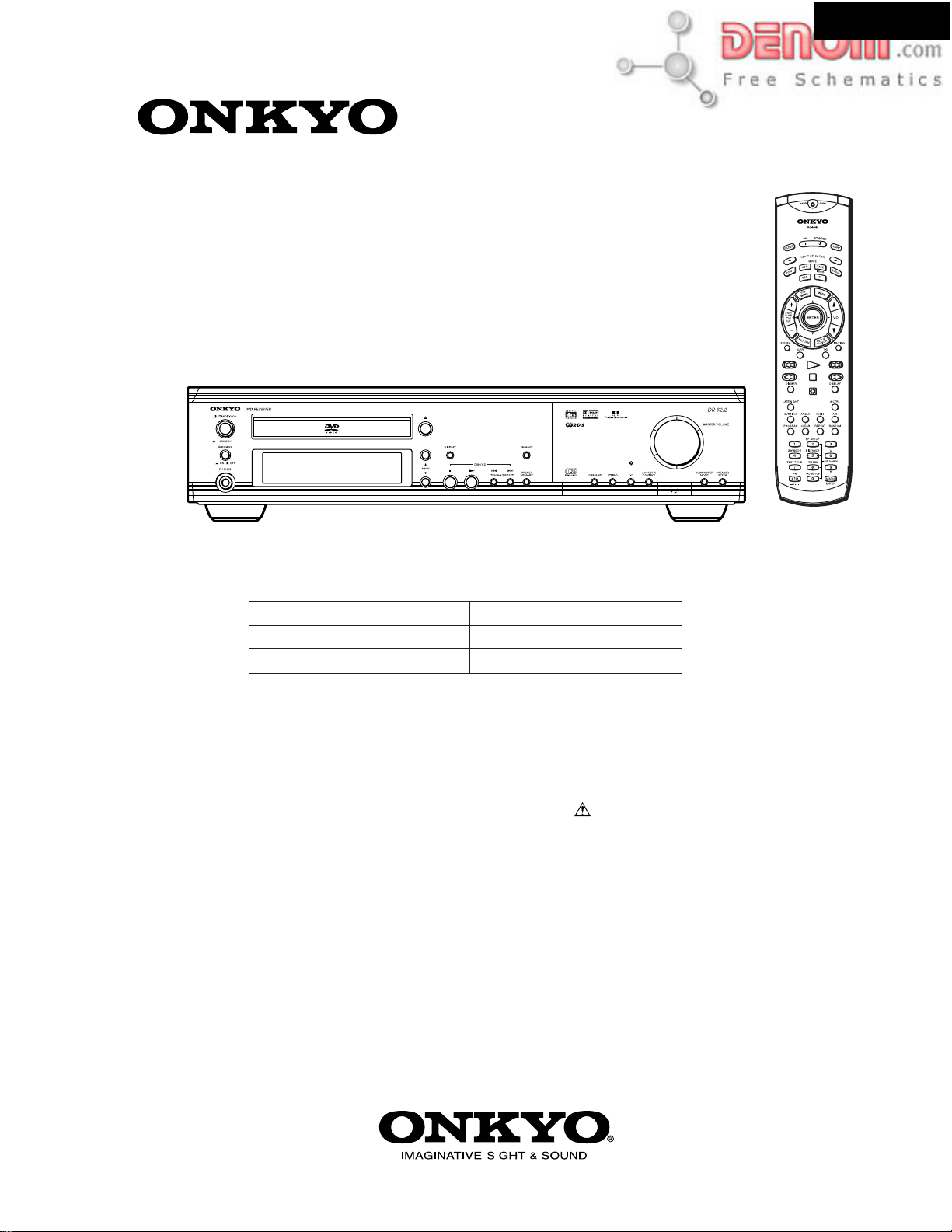
DVD RECEIVER
MODEL DR-S2.2
DR-S2.2
Ref. No. 3721
42002
Titanium color model
UDD1N, UDT3P, UDS4P
UGK3P, UGR6P
UPP2P, UPA4P
SAFETY-RELATED COMPONENT
WARNING!!
COMPONENTS IDENTIFIED BY MARK ON THE
SCHEMATIC DIAGRAM AND IN THE PARTS LIST ARE
CRITICAL FOR RISK OF FIRE AND ELECTRIC SHOCK.
REPLACE THESE COMPONENTS WITH ONKYO
PARTS WHOSE PART NUMBERS APPEAR AS SHOWN
IN THIS MANUAL.
MAKE LEAKAGE-CURRENT OR RESISTANCE
MEASUREMENTS TO DETERMINE THAT EXPOSED
PARTS ARE ACCEPTABLY INSULATED FROM THE
SUPPLY CIRCUIT BEFORE RETURNING THE
APPLIANCE TO THE CUSTOMER.
RC-484M
120V AC, 60Hz
220-230V AC, 50/60Hz
230-240V AC, 50/60Hz
www.denom.com
Page 2
SPECIFICATIONS
Page 2
AMPLIFIER SECTION
Power Output
Continuous power output (DIN)
Continuous Power output (EIAJ)
Dynamic Power 6 ohms: 42 W (L/R)
Total Harmonic Distortion 5 % at rated power
IM Distortion 5 % at rated power
Damping Factor 40 at 8 ohms
Input Sensitivity and Impedance
VIDEO 1 DIGITAL INPUT (OPT) –21 to –15 dBm
VIDEO 2 DIGITAL INPUT (COAX) 0.5 Vp-p, 75 ohms
DVD SECTION
Signal readout system Optical non-contact
Linear velocity 3.49 m/s (Single Layer)
Error correction system Reed Solomon Product Code
Signal system North American model: NTSC
Regional restriction code USA and Canadian area: 1
(FTC) All channels 40 watts per channel min.
RMS. into 6 ohms two channel driven,
1,000 Hz with no more than 5 % total
harmonic distortion.
All channels 30 watts per channel min.
RMS. into 6 ohms two channel driven,
1,000 Hz
All channel 45 watts per channel min.
RMS. into 6 ohms two channel driven,
1,000 Hz
8 ohms: 35 W (L/R)
0.2 % at 1 watt output
0.2 % at 1 watt output
3.84 m/s (Dual Layer)
Other models: PAL/Auto
European area: 2
South-east Asian area: 3
Australian and South American area: 4
PRC: 6
DR-S2.2
LINE (VIDEO 1, VIDEO 2/CDR/PC, TV/LINE, TAPE/MD/HD)
Composite (VIDEO 1, VIDEO 2/CDR/PC) 1 Vp-p, 75 ohms
S-VIDEO (VIDEO 1, VIDEO 2/CDR/PC) Y: 1 Vp-p, 75 ohms
Output Level and Impedance
DIGITAL OUTPUT (OPT) –21 to –15 dBm
REC OUT (TAPE/MD/HD, VIDEO 2/CDR/PC)
PRE OUT (SUBWOOFER) 1 V, 470 ohms
Composite (MON OUT , VIDEO 1) 1 Vp-p, 75 ohms
S-VIDEO (MON OUT , VIDEO 1) Y: 1 Vp-p, 75 ohms
COMPONENT VIDEO OUTPUT Y: 1.0 Vp-p, 75 ohms
(Except European model) PB/PR: 0.7 Vp-p, 75 ohms
RGB (European model) 0.7 Vp-p, 75 ohms
Frequency Response 20 to 30,000 Hz : +/ – 0.8 dB
Acoustic Control 1: +9 dB at 120 Hz
Signal-to-noise Ratio 100 dB (0.5 V INPUT LINE)
Muting –50 dB
Laser Semiconductor laser
Frequency response 10 Hz to 44 kHz (96 kHz)
Signal-to-noise ratio (digital audio) More than 100 dB
Audio dynamic range (digital audio) More than 93 dB
Harmonic distortion (digital audio) Less than 0.025%
Wow and flutter Below threshold of measurability
Operating conditions Temperature: 5 C to 35 C (41 F to 95 F),
2: +9 dB at 120 Hz
+6 dB at 10,000 Hz
, wavelength DVD 650 nm CD 780nm
Operation status: Horizontal
200 mV/50 kohms
C: 0.28 Vp-p, 75 ohms
200 mV, 2.2 kohms
C: 0.28 Vp-p, 75 ohms
TUNER SECTION
Tuning Range FM: 87.50 to 108.00 MHz (50 kHz steps)
Usable Sensitivity FM: Mono 11.2 dBf, 1.0 µV (75 ohms IHF)
50 dB Quieting Sensitivity FM: Mono 17.2 dBf, 2.0 µV (75 ohms)
Capture Ratio FM: 2.0 dB
Image Rejection Ratio FM: (North American and South American models)
IF Rejection Ratio FM: 90 dB
Signal-to-noise Ratio FM: Mono 73 dB, IHF
Alternate Channel Att. (+/ – 400 kHz) FM: Mono 55 dB, IHF
Selectivity FM: 50 dB, DIN 55dB, IHF
AM Suppression Ratio FM: 50 dB
AM: (North American and South American models)
530 to 1710 kHz (10 kHz steps)
Stereo 17.2 dBf, 2.0 µV (75 ohms IHF)
AM: 30 µV
Stereo 37.2 dBf, 20.0 µV (75 ohms)
40 dB
AM: 40 dB
AM: 40 dB
Stereo 67 dB, IHF
AM: 40 dB
0.9 µV (75 ohms DIN)
23 µV (75 ohms DIN)
Harmonic Distortion FM: Mono 0.2 %
Frequency response FM: 30 to 15,000 Hz (+/– 1.0 dB)
Stereo Separation FM: 45 dB at 1,000 Hz
Stereo Threshold FM: 17.2 dBf, 20 µV (75 ohms)
GENERAL
ower Supply Rating (North American and South American models)
P
and Power Consumption AC 120 V, 60Hz
(Other models)
AC 120V, 60Hz 170 W
AC 230-240 V, 50Hz 170 W
Specifications and features are subject to change without notice.
2.0 A
Dimensions (W x H x D)
Weight
(Other models)
522 to 1611 kHz (9 kHz steps)
(Other models)
85 dB
Stereo 0.3 %
AM: 0.7 %
30 dB at 100 to 10,000 Hz
435 x 101 x 428 mm (17
8.8 kg (19.4 lb.)
1/8
x 4 x 16
13/16
ins.)
www.denom.com
Page 3
SERVICE PROCEDURES-1
Page 3
PROTECTION OF EYES FROM LASER BEAM DURING SERVICING
This set employs two lasers. Therefore, be sure to follow
carefully the instructions below when servicing.
WARNING!!
SERVICE WARNING : DO NOT APPROACH THE
LASER EXIT WITH THE EYE TOO CLOSELY.
IN CASE IT IS NECESSARY TO CONFIRM LASER
BEAM EMISSION, BE SURE TO OBSERVE FROM
A DISTANCE OF MORE THAN 30cm FROM THE
SURFACE OF THE OBJECTIVE LENS ON THE
OPTICAL PICKUP BLOCK.
WARNING
Laser Diode Properties
DVD
Wavelength:
Laser output:
650 nm
0.6 mW
CD
Wavelength:
Laser output:
780 nm
0.43 mW
DR-S2.2
WARNING:
TO REDUCE THE RISK OF FIRE OR ELECTRIC SHOCK,
DO NOT EXPOSE THIS APPLIANCE TO RAIN OR
MOISTURE.
CAUTION:
TO REDUCE THE RISK OF ELECTRIC SHOCK, DO NOT
REMOVE COVER (OR BACK). NO USER-SERVICEABLE
PARTS INSIDE. REFER SERVICING TO QUALIFIED
SERVICE PERSONNEL.
LASER W ARNING
This unit contains a semiconductor laser system and is classified
as a "CLASS 1 LASER PRODUCT". So, to use this model
properly, read this Instruction Manual carefully
trouble, please contact the store where you purchased the unit.
To prevent being exposed to the laser beam, do not try to open
the enclosure.
CAUTION:
VISIBLE LASER RADIATION WHEN OPEN AND INTERLOCK
FAILED OR DEFEATED. DO NOT STARE INTO BEAM.
CAUTION:
THIS PRODUCT UTILIZES TWO LASERS. USE OF CONTROLS OR
ADJUSTMENTS OR PERFORMANCE OF PROCEDURES
OTHER THAN THOSE SPECIFIED HEREIN MAY RESULT IN
HAZARDOUS RADIATION EXPOSURE.
. In case of any
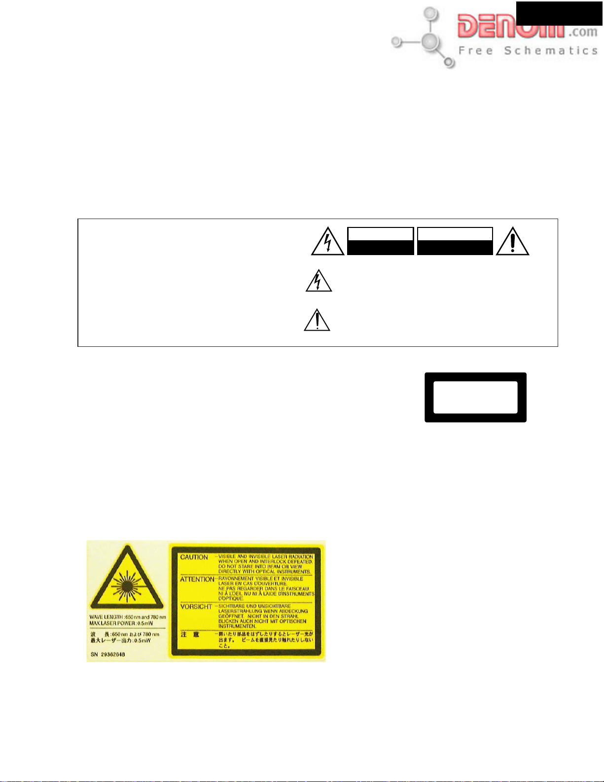
WARNING
RISK OF ELECTRIC SHOCK
DO NOT OPEN
The lightning flash with arrowhead symbol, within an equilateral
triangle, is intended to alert the user to the presence of uninsulated
"dangerous voltage" within the product's enclosure that may be of
sufficient magnitude to constitute a risk of electric shock to persons.
The exclamation point within an equilateral triangle is intended to alert
the user to the presence of important operating and maintenance
(servicing) instructions in the literature accompanying the appliance.
The label on the right
is applied on the rear
panel except for USA
and Canadian
models.
1. This unit is a CLASS 1 LASER PRODUCT and employs two
lasers inside the cabinet.
2.To prevent the laser from being exposed, do not remove
the cover. Refer servicing to qualified personnel.
AVIS
RISQUE DE CHOC ELECTRIQUE
NE PAS
OUVRIR
"CLASS 1 LASER
PRODUCT"
LASER BEAM CAUTION LABEL
www.denom.com
Page 4
SERVICE PROCEDURES-2
Page 4
SERVICE PROCEDURE
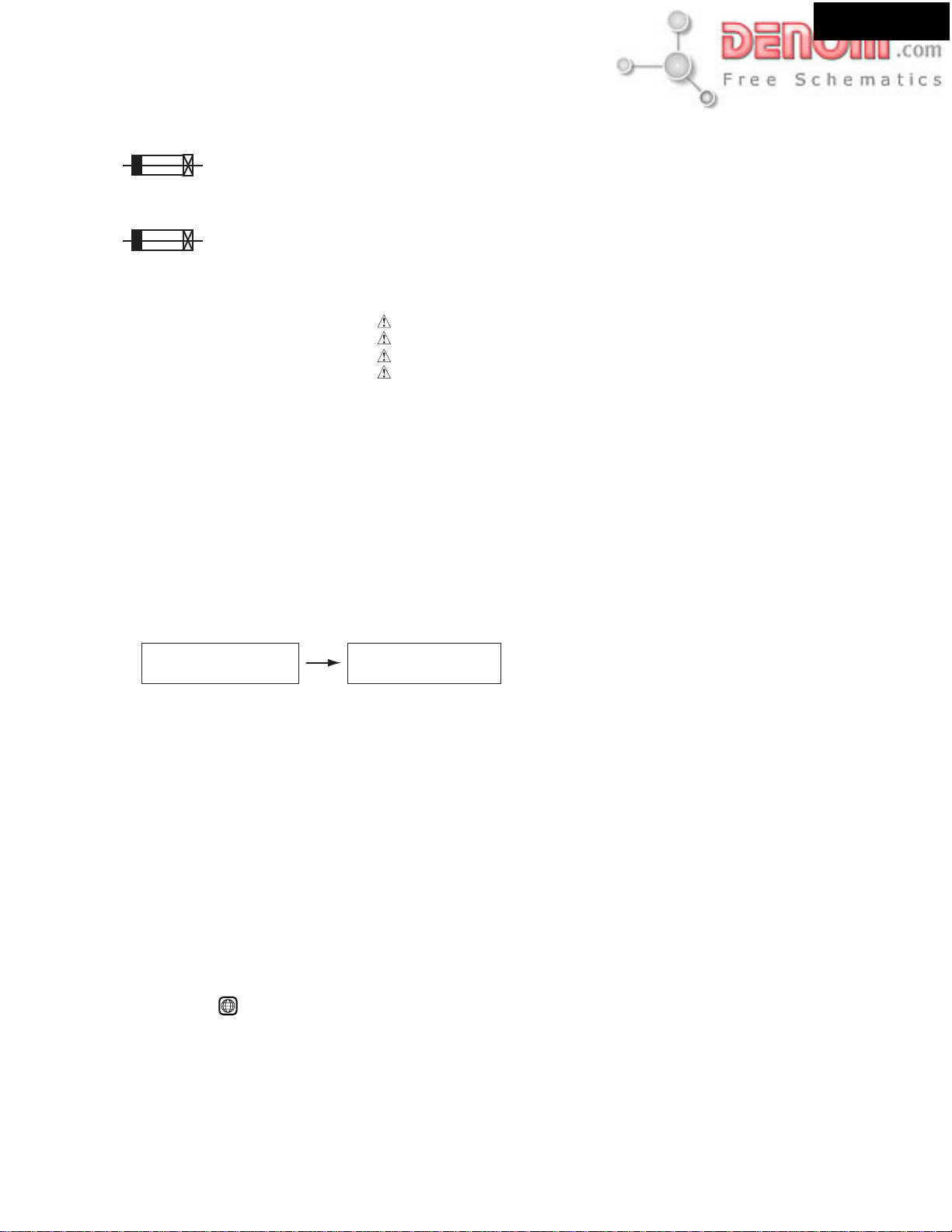
1. Replacing the fuses
This symbol located near the fuse indicates that the
fuse used is show operating type, For continued protection against
fire hazard, replace with same type fuse , For fuse rating, refer to
the marking adjest to the symbol.
DR-S2.2
Ce symbole indique que le fusible utilise est e lent.
Pour une protection permanente, n'utiliser que des fusibles de meme
type. Ce demier est indique la qu le present symbol est apposre.
REF NO.
F9921
DESCRIPTION
4A-SE-EAK
4A-UL/T-237
1.25A-SE-EAWK
3.15A-UL/T-237
PART NO.
252077
252163
252071
252162
REMARKS
PP2P, PT3P, GK3P, PA4P, GR6P
DD1N, DT3P, DS4P
PP2P, PT3P, GK3P, PA4P, GR6P
DD1N CDT3P, DS4
[NOTES]
DD1N: North American area (Regional code-1)
PP2P: European area (Regional code-2)
GK3P: Korean area (Regional code-3)
DT3P: Some Asian area (AC 230V, Regional code-3)
PT3P: Some Asian area (AC 120V, Regional code-3)
PA4P: Australian area (Regional code-4)
DS4P: South America area (Regional code-4)
GR6P: Chinese area (Regional code-6)
2. Safety-check out
(Only U.S.A. model)
After correcting the original service problem perform the following safety check before releasing the set to the customer
Connect the insulating-resistance tester between the plug of power supply cord and terminal GND on the back panel.
Specifications: More than 10M ohm at 500V
3. To initialize the unit.
1. Connect power supply cord to the wall outlet.
2. Press POWER to switch on the main power to put the unit in the standby mode.
(European and some Asian models only)
3. Press STANDBY/ON the unit or remote controller to turn on unit.
4. Press the hold down SPEAKER SETUP button, the press STANDBY/ON button.
FL display
clear
The memory of unit is initialized.
(The shipment state of the product)
5. Press POWER to switch off the main power
(European and some Asian models only)
6. Disconnect power supply cord from the wall outlet.
4. Changing the AM band step
With the exception of the worldwide models, a tuning step selector switch is not provided. When you change the band step,
change the parts as shown below.
To 10kHz To 9kHz
R8058 10 k ohms None
R8059 1 .5 k ohms 10 kohms
R8058 and R8059 on
NADG-7452 (DSP and microprocessor PC board)
5. Regional Restriction Codes (Region Number)
Regional restriction codes are built into DVD Receivers and DVD
videos for each sales region. If the regional code of the DVD
Receiver does not match one of the regional codes on the DVD
video, playback is not possible.
The regional number can be found on the rear panel of the DVD
Receiver. (e.g.
1
for Region 1)
www.denom.com
Page 5
DR-S2.2
+7V
IN
P U
UN
Page 5
A
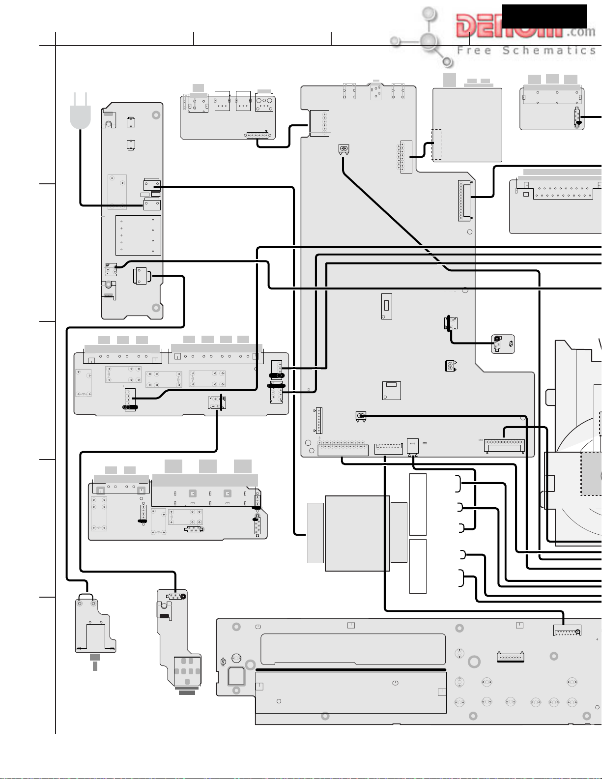
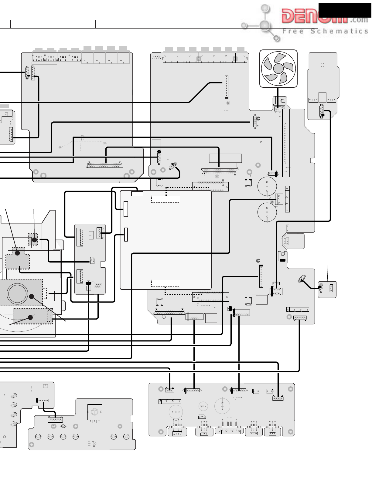
PC BOARD CONNECTION DIAGRAM
AC IN
1
E9991
E8601 P8601
F9991
U16
DIGITAL TERMINAL
P9992A
AC-CORD
PT
RL9991
SUB
JL9991B
2
TRANSFORMER
E9992
T9992
P9995A
AC-H
P9991A
AC-GAC-H
AC-G
AC-GAC-H
PC BOARD
NAETC-7442
U2
POWER SUPPLY
(primary)PC BOARD
NAPS-7429
U8602U8603
U8601
JL8602A
BCD
+5VDSP
RX2
JL8602B
P8201A
E8101
WHT
BLK
P8004
U26
DSP PC BOARD
NADG-7452
Q8306
E8102
P8401
U31
TUNER UNIT
ADCL
P8701B
TUR
JL8501B
U7
THERMAL
PROTECTER
PC BOARD
NAETC-7433
0
R8504
P1701
JL1701B
U15
COMPONENT TERM
NAVD-7441
Except UPP2P type
1
U14
P1801
AV CONNECTOR
PC BOARD
NAVD-7440
UPP2P type only
PICKU
E
SR-L+
C+
P5012
RL5402
3
RL5403
JL5002B
SPEAKER TERMINAL
U29
PC BOARD
(Except UDD1N,UDS4P type)
LS
RL5403
4
U4
NAAF-7431
BRN
YEL
P9995
S9992
5
U3
NASW-7430
POWER SWITCH
PC BOARD
Except UDD1N, UDS4P,UDT3P
SR-R+
E
E
RL5404
L-B+
JL5003B
R-B+
E
P5011
RL5401
FR+
E
FL+
EE
NAAF-7510
RS
P5012
RS
LS
JL5002B
C
RL5402
RL5401
E
HPIN
HPR
P5011
FL
HPL
E
JL5003B
L
JL5004B
SPEAKER TERMINAL PC BOARD
(UDD1N,UDS4P type only)
JL5003A
U5
NAETC-7432
LER
E
HPIN
HEAD PHONE
PC BOARD
E7601
P7601
D7006
STANDBY/ON
S7001
GND
R
GND
JL5001B
JL5004B
JL5001B
HPIN
E
-20V
FRL
E
CSRL
SPBRL
P8003
MICONGND
MCRDY/FPHS
P8002B
XLT
T991
MAIN POWER
TRANSFORMER
Primary
U10
DISPLAY PC BOARD
NADIS-7436
P8009A
Q7001
+5.6V
J8001
RI
Q8001
P7001A
P8501
P8005
F2
RED
BLACK
RED
BLACK
TOPBOTTOM
BLACK
GREEN
GREEN
YELLOW
YELLOW
RED
BLACK
BLACK
secondary
EJECT
S7002
S7003
INPUT_UP
INPUT_DOWN
S7004
+7V
DISPLAY
S7006
STOP
S7005
JL8501A
P8001B
+5V
IC
NC
PLAY
S7007
-VP
LOADING
MOTOR
P7003
RST
CLK
GND
SI
SO
S7008 S7009
P7001B
UPDOWN
22
2
FM_MUTE
2
S7011
PRESET
S7010
SUBRDY
LEDGND
SUBDO
+7V
LEDGND
SUBDI
SUBCK
RI
www.denom.com
Page 6
INAL
Page 6
7
FSW
7
RGBSW
P1802B
P UNIT
G
UNIT
EFGH
P1004
P1006
P1007
JL1701A
P1802A
SLED MOTOR
UNIT
U13
VIDEO PC BOARD
NAVD-7439
J1B
P1005
P1001
J1070
P1002B
U27
CONNECTOR
PC BOARD
NAETC-7453
P0003A
P8009
P0002A
PICKUP
UNIT
P1001
P0005A
P0001A
DUMMY
MOTOR-
CLOSESW
SW1GND
SW2
V+3D
LOADLOAD+
MOTOR+
OPENSW
J1A
SWGND
P0004A
P4001
SW5V
TXD
DTR
RXD
CTS
GND
HPIN
MICONGND
-20V
SPAFRRL
GND
SPACSRL
SPBRL
JL5004A
CN51
CN61
U30
DVD MAIN PC BOARD
CN151
DB-VPB303A
/ DB-VPB304
CN401
DVDSPDIF
+13V
XLT
XRESET
XSCLKA
XSOA
XSI
OUT IN OUT
IN
TV/LINE
TAPE/MD//HD
VIDEO1
U1
MAIN PC BOARD
NAAR-7428
JL9991A
POWRL
+13V
GND
P8002A
VCTLB
VCTLA
IPM
XREADY
CN401
AMUT
HPIN
VPRT
POWERRL
SPAFRRL
SPACSRL
SELSCLK
SELSDO
SELMUT
SWNONE
CN15
+5VDSP
SPBRL
+5.6V
MICONGND
CN15
JL9001B
P1002A
MCLK
GND
BCK
GND
SW+5V
GND
M+6V
M+6V
30
XCSDF0
XSCK
ADATA0
LRCK
SW+3.3V
GND
SW+12V
GNDM
GNDM
XSI
SW+3.3V
NC
SW+2.5V
GND
SW+2.5V
XMUT
NCNCNC
GND
SW+2.5V
22
GND
VCTLB
VSEL1
GND
SW+3.3V
VCTLA
NC
NC
M+6V
+5VDSP
GND
VSEL2
CTS
NC
GNDM
P3002P3001
GND
GND
GND
PRGCB
PRGCR
DTR
XLT
XRESET
SW+5VGND
SW+5VIN
IN
SW+6V
+12V
GND
PRGY
RXD
XSI
V2/CDR/PC
GND
GND
+7V
-7V
P4007A
GND
C
V
G/Y
B/CB
DVDSPDIF
SQUEEZE
TXD
XSCLKA
XSOA
P8701A
SQUEEZ
LETTER
VSEL1
VSEL2
GND
GND
Y
R/CR
LETTER
XREADY
P8201
PRGCR
ADCL
ADCR
AGND
DACR
DACL
DACRS
DACLS
DACSW
DACC
AGND
TUL
AGND
TUR
PRGCB
GND
P4006A
B/CB
PRGY
GND
G/Y
GND
V
JL9002B
+5VDSP
GND
P3003
SWOUT
R/CR
C
DSPGND
Y
MICOMGND
+5.6V
FAN
P4006B
+13V
DVDPOW
E
C
RS
LS
MICOMGND
DVDPOWER
TUGND
+5VDSP
+5VDSP
DSPGND
DSPGND
+5.6V
COOLING FAN
E
J1B
FAN
P6501
JL5002A
JL5001A
E
C5903
J1A
C5904
+7V
GND
-7V
+12V
P8001A
-VP
SW+5V
SW+5VGND
+19V
SW+5VIN
GND
DVDPOW
SW+12V
JL9003B
Q5001
22
E
FL
FR
P9901A
E9901
Q9905
P4007B
Q9901
D5901
Q9903
+7V
U6
REGULATOR
PC BOARD
NAETC-7433
JL9101A
D9901
P9902A
DR-S2.2
U23
NAETC-7449
REGULATER
DVDPOW
+5VGND
Q9927
+19V
SW+5V
SW+12V
SW+5VIN
GND
JL9003A
JL9101B
PC BOARD
Q9902
Q9904
LEDGND
SUBDO
RESET
+7V
GND
-VB
LEDGND
F1
+5.6V
SUBCK
+7V
GND
F2
D7010
D7005
D7009
D7004
VBJ
P7002A
K2
SURROUND STEREO
S7013
U11
OPERATION SWITCH PC BOARD
RIMO
LED
GND
+5V
VAJ
K2
NASW-7438
MASTER_VOLUME
S7019
S7014
D7008
S7015
T-D
P7002B
T-D_LED
S7016
A.CTRL
REMOTE SENSOR
SUBWOOFER_MODE
Q7008
S7017
SP_SETUP
2 2
S7018
LED
GND
+5V
VAJ
VBJ
RIMO
P9904A
D9951
Q9951
JL9001A
M+6V
MGND
DVDGND
SW3.3V
SW5VIN
SW2.5V
SW5VGND
C9933
C9953
12
121212
Q9924
U11
POWER SUPPLY PC BOARD
Q9925
JL9002A
C9923
15
12
D9921
MICOMGND
15
12
Q9921
P9903A
Q9926
F9921
+13V
+5.6V
+5VDSP
GND
DSPGND
DVDPOW
NAPS-7437
www.denom.com
Page 7
DR-S2.2
+
N
Page 7
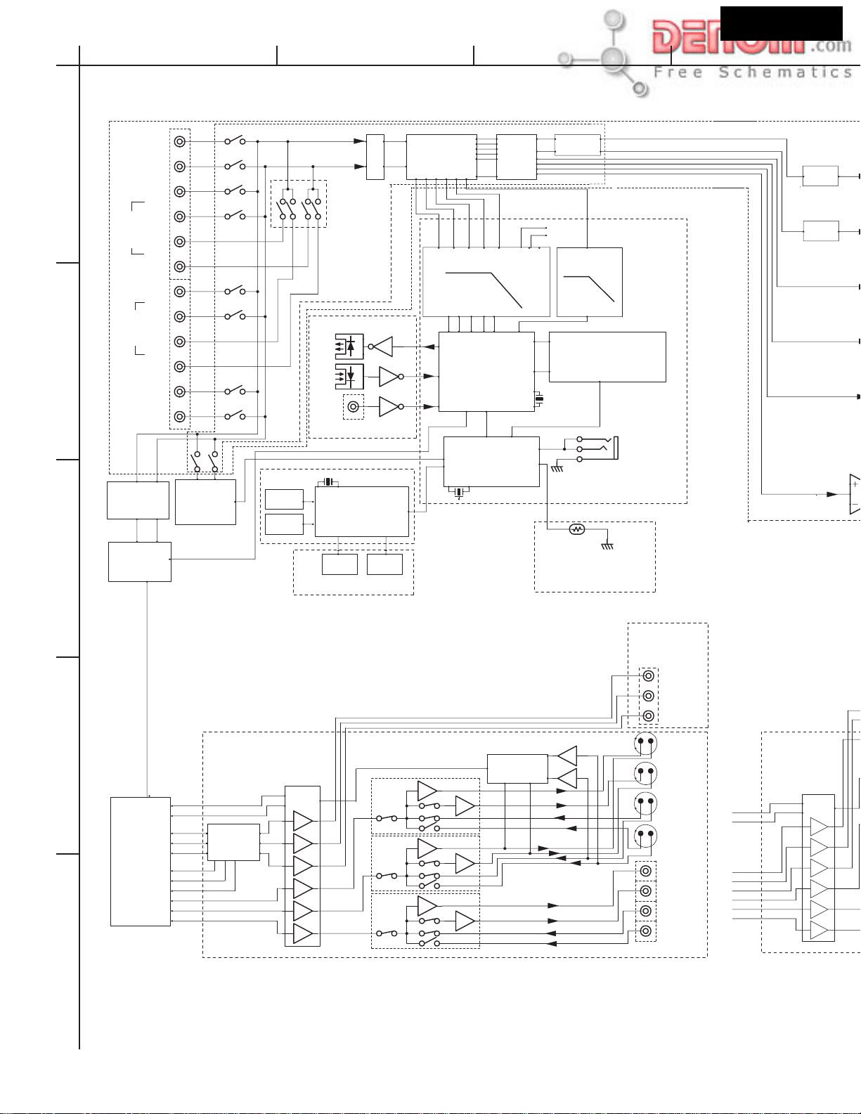
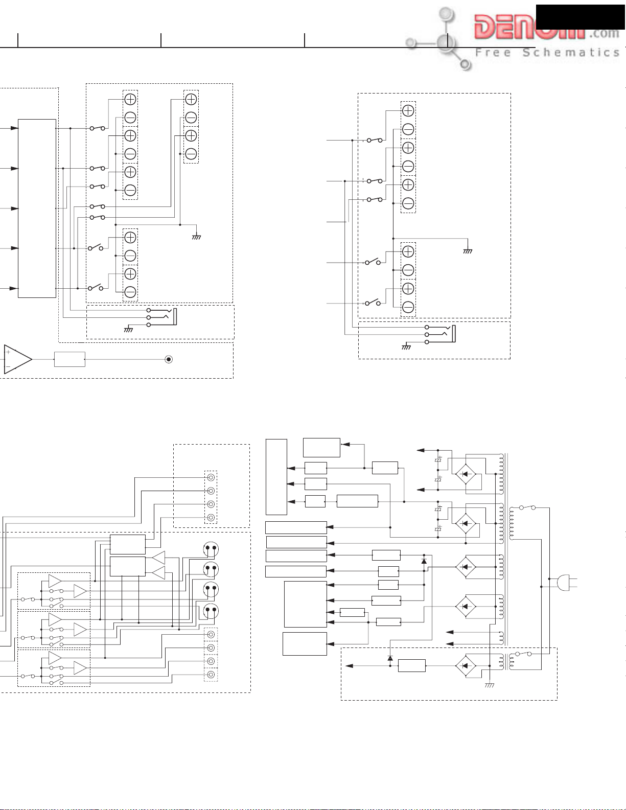
A
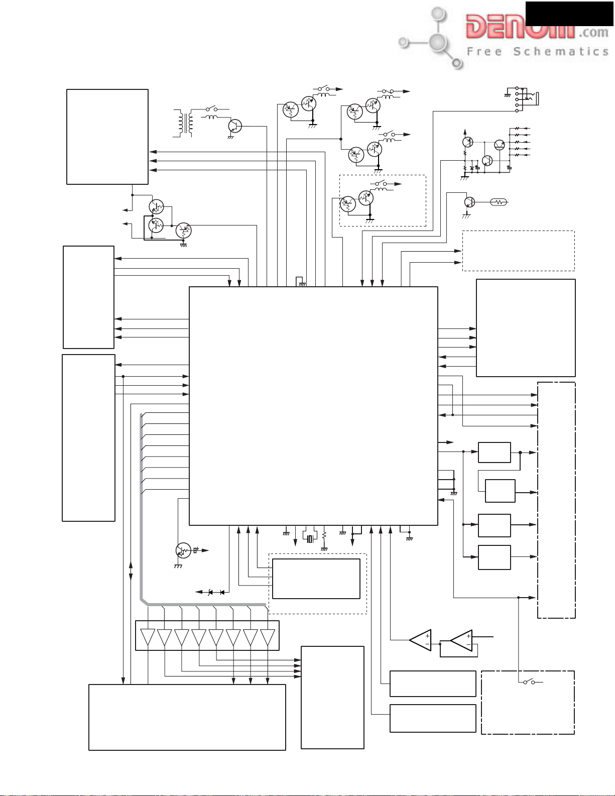
BLOCK DIAGRAMS
LEFT
1
2
3
TV/LINE
RIGHT
IN
TAPE
MD
HDD
OUT
IN
V2
CDR
PC
OUT
VIDEO1
DAC
PCM1742KE
DVD
BOARD
L
R
L
R
TUNER
UNIT
DVD SP DIF
L
NADIS-7436
FL TUBE
KEY
NASW-7438
Rec SW
R
NAETC-7442
OPT
OUT
OPT
IN
COAXIAL
IN
MPD780232GC
MICRO PROCESSOR
DISPLAY CONTROL
LED
BCD
L
R
C
SL
SR
Q3001
BD3811K1
5.00MHz
MUTE SW
2
1
1
KEY
1
2
2
5.1ch mode
SWITCH
(DVD DSP)
VOLUME
50kHz LPF
AK4586
D/A A/D
Converter
DIR
MPD784225GC
MICRO PROCESSOR
AUDIO CONTROL
12.5MHz
Acoustic
Control
+7V
-7V
SUBWOOFER
5kHz LPF
CS493292-CL
CRYSTAL
DIGITAL SIGNAL PROCESSOR
12.288MHz
THERMISTOR
Thermal Protect
for Power AMP
NAETC-7434
RI
REMOTE
CONTROL
NADG-7452
MUTE
MUTE
NAVD-7441
Pb
Except UPP type
NAVD-7439
4
Q1001
DVD
MECHANISM
LETTER
SQUEEZE
PRG Y
PRG Cr
Cr
Y
Cb
Y
C
V
PRG/INT
SELECTOR
TC74HC4053AF
LA73054
S1/S2
1
1
1
1
1
1
2
2
2
2
2
2
NJM2279M
NJM2279M
NJM2279M
2
1
1
2
1
1
2
1
1
TC74HC4053AF
2
2
2
S1/S2
1
2
1
2
Y
Pr
MONITOR
OUT
VIDEO 2
OUT
VIDEOB 2
IN
VIDEO 1
IN
MONITOR
OUT
VIDEO 2
OUT
VIDEO 2
IN
VIDEO 1
IN
COMPONENT
S-VIDEO
LETTER
SQUEEZE
R
G
B
Y
C
V
NAVD-7439
LA73054
S1/S2
1
1
1
1
1
1
2
2
2
2
2
2
5
www.denom.com
Page 8
DR-S2.2
Page 8
EFGH
NAAR-7428
L
R
C
SL
R
+15dB
RELAY
STK402-950
Q5001
POWER AMPLIFIER
MUTE
UDD1N type only
FRONT
LEFT
SP A
FRONT
RIGHT
CENTER
SURROUND
LEFT
SURROUND
RIGHT
SUB WOOFER
FRONT
LEFT
SP B
FRONT
RIGHT
NAAF-7510
PHONES
NAETC-7432
PREOUT
Except UDD1N
RELAY
L
FRONT SPEAKERS
R
CENTER
LEFT
SURROUND
SPEAKERS
RIGHT
NAAF-7431
PHONES
NAETC-7432
NJM2279M
NJM2279M
NJM2279M
UPP Type only
2
1
1
1
2
1
2
2
1
2
2
1
TC74HC4053AF
RGB SELECTOR
TC74HC4053AF
S1/S2
2
2
NAVD-7440
1
1
GREEN
BLUE
Cv/Y
RED/Cb
MONITOR
OUT
V2
OUT
V2
IN
V1
IN
MONITOR
OUT
V2
OUT
V2
IN
V1
IN
AV CONNECTOR
SPEAKER RELAY
MICROPROCESSOR
S-VIDEO
COMPOSITE
TUNER
UNIT
+7V
-7V
OP AMP,VIDEO etc.
+6V
FL TUBE
-Vp
DSP
DVD
BOARD
PCM1742KE
DAC
+12V SW
-26.4V
+2.5V
NAPS-7429
Poff
+12V
+5.6V
+5V
+6V
+5V SW
+3.3V
+B
POWER
AMP.
-B
+19V
-20V
+13V
+9.5V
+5V
AC
POWER TRANSFORMER
RELAY
POWER
SWITCH
SUB TRANSFORMER
AC IN
www.denom.com
Page 9

MICROPROCESSOR TERMINAL DESCRIPTION-1
Page 9
Q8001: MPD784225GC-165-8BT
I/OPIN NAMENO. DESCRIPTIONACTIVE
DR-S2.2
TRAYIN
1
NU
2
NU
3
NU
4
NU
5
DVDPOWER
6
AVREF
7
XS1
8
NU
9
XCLK
10
XRESET
11
XSO
12
XSCLK
13
XREADY
14
MDRDY/FPHS
15
MCSD/FPSI
16
MCSDO/FLSO
17
MCCLK/FPCLK
18
MCRST
19
NU
20
VCTLA
21
VCTLB
22
NU
23
TPRT
24
VPRT
25
HPIN
26
NU
27
SPB
28
SWNONE
29
SELSDO
30
SELSCLK
31
SELMUT
32
VSS1
33
SPACS
34
SPAFR
35
POWERL
36
AMUT
37
TUMUT
38
SD
39
STEREO
40
A/D
I
O
I
I
O
O
O
O
I
I
O
O
O
O
O
I
I
I
O
O
O
O
O
O
O
O
O
O
I
I
H
H
CLK
H
H
CLK
H
H
H
H
CLK
L
H
H
L
H
H
H
H
H
CLK
H
H
H
H
H
H
H
L
L
Input pin of detected signal of tray state.
No used (Connect to ground)
No used (Connect to ground)
No used (Connect to ground)
No used (Open)
Output pin of control signal for power supply of DVD main circuit.
Input pin of reference voltage or D/A converter.
Input pin of latch signal from microprocessor in DVD main board.
No used.
Input pin of clock signal from microprocessor in DVD main board.
Output pin of reset signal to microprocessor in DVD main board.
Output pin of data to microprocessor in DVD main board.
Output pin of clock signal to microprocessor in DVD main board.
Output pin of communication for microprocessor in DVD main board.
Input pin of ready data from Sub-microprocessor.
Input pin of data from sub-microprocessor.
Output pin of data to sub-microprocessor.
Output pin of serial clock to sub-microprocessor.
Output pin of reset signal for Sub-microprocessor.
No used
Output pin-1 of control signal for video signal.
Output pin-2 of control signal for video signal.
No used
Input pin of signal from thermal detection circuit.
Input pin of DC voltage detection signal from power amplifier.
Input pin of detection signal from insert state of headphone plug.
No used.
Input pin of control signal for seaker-B relay drive.
No use.
Output pin of serial data latch for BD3811 (volume and selector control IC).
Output pin of serial data clock for BD3811 (volume and selector control IC).
Output pin of muting signal for BD3811 (volume and selector control IC).
Ground pin.
Output pin of control signal for center speaker relay and surround speaker relay drive.
Output pin of control signal for front speaker relay drive.
Output spin of control signal for main power relay drive.
Output pin of control signal for audio muting circuit.
Output pin of control signal for of tuner muting circuit.
Input signal of detection signal of receiving state of broadcast.
Input pin of detection signal of FM stereo pilot signal.
www.denom.com
Page 10

MICROPROCESSOR TERMINAL DESCRIPTION-2
Page 10
Q8001: MPD784225GC-165-8BT
I/OPIN NAMENO. DESCRIPTIONACTIVE
DR-S2.2
PLLSDO
41
PLLCLK
42
PLLCE
43
NU
44
NU
45
DIRCS
46
DSPSDI
47
DIRINT1
48
DIRINT0
49
INTREQ/ABOOT
50
DSPCS
51
ROM/RAM
52
ADDR15
53
ADDR16
54
ADDR17
55
DSPCLK
56
DSPSDO
57
DSPRST
58
DIRPD
59
RESET
60
POFF
61
RDSCLK
62
RDSDATA
63
RDSSIG
64
XLT
65
NU
66
VSS0
67
VDD1
68
X2
69
X1
70
TEST
71
XT2
72
XT1
73
VDD0
74
AVDD
75
BAND
76
DVDBAND
77
IPM
78
NU
79
NU
80
O
O
O
O
I/O
O
O
O
O
O
O
O
O
O
H
CLK
H
-
-
I
I
I
I
I
I
I
I
-
-
-
-
-
-
-
-
-
I
I
I
-
-
-
H
H
H
H
H
L
L/H
H
H
H
H
H
L
L
-
L
CLK
H
H
H
-
-
-
-
-
-
-
-
-
A/D
A/D
A/D
-
-
Output pin of serial data for PLL IC of tuner unit.
Output pin of serial clock for PLL IC of tuner unit.
Output pin of serial latch for PLL IC of tuner unit.
No used.
No used.
Output pin of chip select signal to AK4586.
Input pin of serial data from CS493292 and AK4586.
Input pin of detection signal from function status of AK4586.
Input pin of interrupt request detection signal from function status of AK4586.
Input/output pin of signal from interrupt request and auto boot of CS493292
Output pin of signal for chip select.
Output pin of signal for select ROM or RAM.
Output pin of signal for select of DSP boot ROM address 15
Output pin of signal for select of DSP boot ROM address 16
Output pin of signal for select of DSP boot ROM address 17
Output pin of serial clock to CS493292 and AK4586.
Output pin of serial data to CS493292 and AK4586.
Output pin of reset signal to CS493292.
Output pin of power down signal to AK4586.
Input pin for system reset.
Input pin of power failure detected signal.
Input pin of clock signal from RDS demodulator.
Input pin of data from RDS demodulator.
Input pin of signal from RDS demodulator.
Input pin of latch signal from DVD main microprocessor.
Not used. (open)
Ground pin.
Power supply pin.
Connect to ceramic oscillator.
Connect to ceramic oscillator.
(No connection)
No used. (open)
No used. (connect to ground)
Power supply pin.
Power supply pin for A/D converter.
Input pin for initial setting about destination (tuner band).
Input pin for initial setting about destination (DVD region cord).
Input pin for IPM (intelligent power management) function.
Not used. (connect to ground)
Not used. (connect to ground)
www.denom.com
Page 11
MICROPROCESSOR CONNECTION DIAGRAM-1
Page 11
DR-S2.2
Q8001: MPD784225GC-165-8BT
MAIN POWER
TRANSFORMER
6ch volume with
8ch input selector
BD3811K1
Q3001
46
47
48
Front
To power
amp. section
Lch
Front
Rch
TUNER UNIT
CSN 19
CDTO 16
INT1 15
INT0 14
Q8201
6ch CODEC with DIR
AK4586
RESET
Q8003
POWER FAILURE
DETECTOR
T9991
RL9991
MUTING
Q3006
41
42
43
44
45
46
47
48
49
50
51
52
53
54
55
56
57
58
59
60
+13V
AC IN
40393837363534333231302928272625242322
STEREO
PLLSDO
PLLCLK
PLLCE
NU
NU
DIRCS
DSPSDI
DIRINT1
DIRINT0
INTREQ/ABOOT
DSPCS
ROM/RAM
ADDR15
ADDR16
ADDR17
DSPCLK
DSPSDO
DSPRST
DIRPD
RESET
POFF
61626364656667686970717273747576777879
+5V
Q9991
AMUT
TUMUT
SD
RDSCLK
RDSDATA
FRONT
SPEAKER
RL5401
NU
SPB
SWNONE
SELSDO
SELSCLK
SELMUT
VSS1
SPACS
SPAFR
POWERL
MICROPROCESSOR
(Audio control)
Q8001
MPD784225GC-165-8BT
NU: No use
RDSSIG
XLTNUVSS0
VDD1X2X1
TEST
XY2
XT1
VDD0
+5V
Q8402
QUAL 1
BU1923F
RDATA 2
RDS
RCLK 16
demodulator
UPP type only
Buffer
TC74VHC541FT
Q8307
+5V
VPRT
HPIN
AVDD
RL5404
TPRT
BAND
CENTER
SPEAKER
RL5402
SURROUND
SPEAKER
RL5403
SPEAKER-B
UDD, UDS
type only
21
VCTLA
VCTLB
NU
20
NU
19
MCRST
XREADY
XSCLK
XSO
XRESET
XCLK
18
17
16
15
14
13
12
11
10
MCCLK/FPCLK
MCSDO/FLSO
MCSDI/FPSI
MDRDY/FPHS
NU
XS1
AVREF
DVDPOWER
NU
NU
NU
NU
TRAYIN
DVDBAND
IPMNUNU
80
Detection circuit of
audio signal input
Switch which
detects insertion
state of headphone
Detection circuit of
speaker output level
+B
Thermal detection circuit
Q8501
9
8
+5V
7
6
5
4
3
2
1
Q3101
P7601
PHONES
Q5802
Q5803
thermistor
R8504
Output signals of
power amplifier
Video signal
control circuit
MICROPROCESSOR
(Display control)
Q7002
Q9951
Q9952
Q9927
Q9902
MPD784225GC
-066-8BT
+3.3V
+2.5V
+5V
+12V
6 RESET
7 SUBCK
8 SUBDO
9 SUBDI
10 SUBRDY
Regulater
DVD MAIN BOARD
CS 18
SCDIO 19
ABOOT 20
Audio Decoder
CS493292-CL
Q8101
SCLK 7
RESET 36
A1 SCDIN 6
www.denom.com
30 CE
11 A15
10 A16
6 A17
CMOS EPROM
MX27L2000
Q8306
INITIALIZING
(Setting of destination )
INITIALIZING
(Setting of FM/AM Band)
Detection switch
of tray open
DVD MECHANISM
(TRAY LOADING UNIT)
Page 12
ADJUSTMENT PROCEDURES-1
Page 12
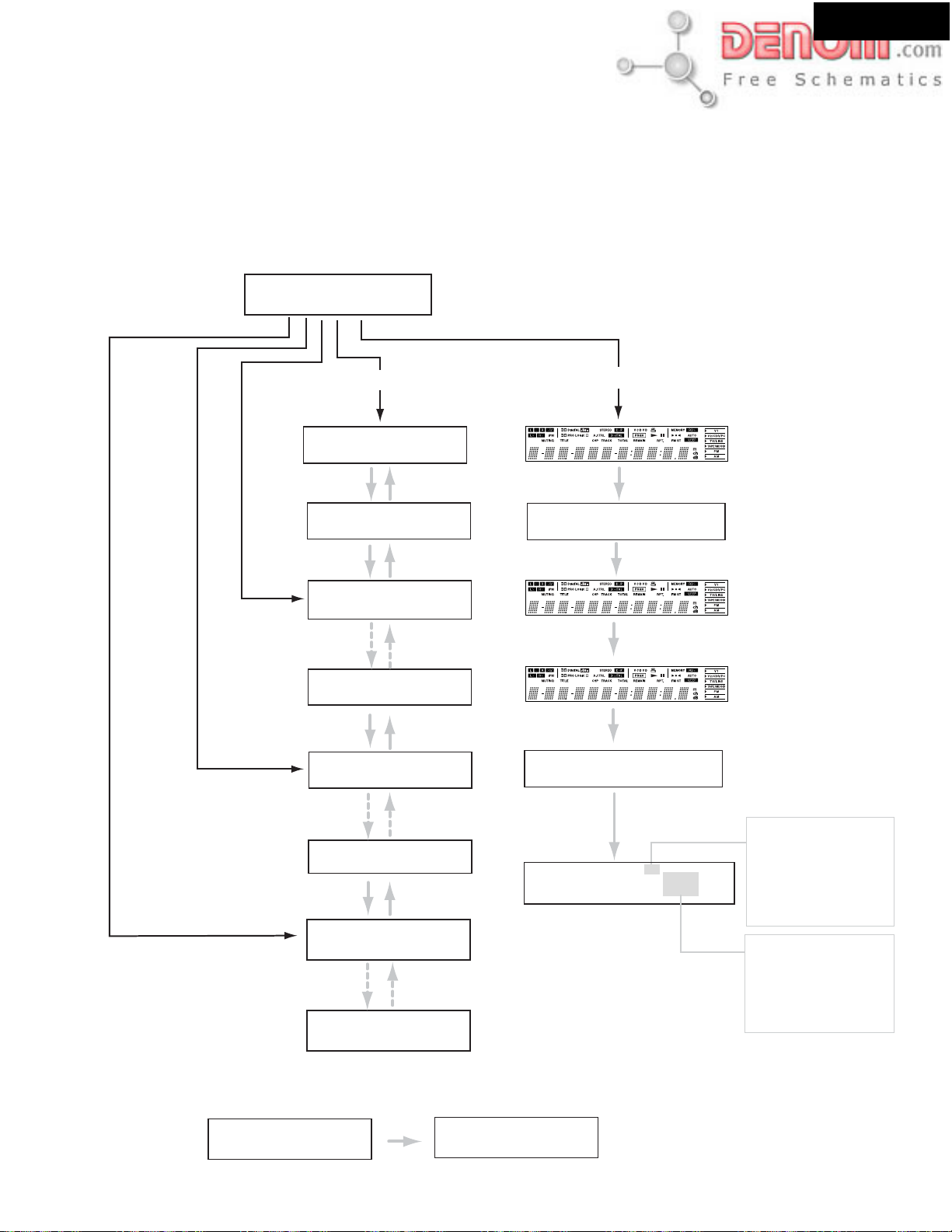
TEST MODE FOR OPERATION
1. How to go in TEST MODE?
[NOTE] All memories are cleared when you go in this mode.
1. Connect the power supply cord to a wall outlet.
2. Press POWER to switch on the main power to put the unit in the standby mode.
(European and some Asian models only)
3. Press
STANDBY/ON
4. Press
SUBWOOFER MODE
toturn on the unit.
as pressing down
SPEAKER SETUP
and
STANDBY/ON
DR-S2.2
together.
Press
ACOUSTIC
PRESENCE
FL display
Press
T-D
Test-_
Press
STEREO
Press
SPEAKER SETUP
Press
SPEAKER SETUP
Press
SPEAKER SETUP
Press
SPEAKER SETUP
Press
SPEAKER SETUP
Press
SPEAKER SETUP
SURROUND MODE
Press
the unit goes in test modes
of functional check as follows.
Test-1-00
Press
SUBWOOFER MODE
Test-1-01
Press
SUBWOOFER MODE
Test-2-00
Press
SUBWOOFER MODE
Test-2-14
Press
SUBWOOFER SMODE
Test-3-00
Press
SUBWOOFER MODE
Test-3-07
Press
SUBWOOFER MODE
If do not do operation for 5 seconds, the unit returns to
the "
NO DISC
" state.
If so, start again from 1.4.
Press
SPEAKER SETUP
the unit goes in test modes
of functional check as follows.
Press
SPEAKER SETUP
BA987654321
Press
SPEAKER SETUP
Press
SPEAKER SETUP
Press
SPEAKER SETUP
No key
Press
SPEAKER SETUP
v
Good-bye US
Lit all segment
Lit an odd number
segment
Lit a even number
segment
Key test mode
The name of the pressed
key is displayed on FL tube.
DVD destination.
"S" Japanese model
"V" : USA model
"C" : South America model
"D" : European model
"VD" Asian model
2. How to cancel TEST MODE?
1. Press STANDBY/ON
Clear
Test-4-00
Press
SUBWOOFER SETUP
Test-4-27
www.denom.com
Tuner band
"EU" : European model
"AS" : Asian model
"US" : USA model
"JP" : Japanese model
Test mode finished.
Page 13
ADJUSTMENT PROCEDURES-2
Page 13
OPERA TION TEST -1
1. Speaker relays
1. Speaker relays turn ON approximately 5 seconds after STANDBY/ON is pressed.
2. Speaker relays turn OFF immediately after STANDBY/ON is pressed OFF.
2. DC detection circuit
1. Set the unit to "TEST-1-00." (Refer to TEST MODE OPERATION)
2. Apply DC voltage (+1.5 to - 3V) to TAPE PLAY terminal, each channel.
3. Check the speaker relays turn OFF immediately.
4. Apply DC voltage (from -1.5 to -3V) to TAPE PLAY terminal, each channel.
5. Check the speaker relays turn OFF immediately.
[NOTE1] Limit time to apply voltage is 0.5 - 1.0 seconds each channel.
When protection operation does not occur at once, try several times.
[NOTE2] Don't connect speakers or any load. Don't short speaker terminals.
[NOTE3] The relay recovers in one second in "TEST-1-00." So it is not held OFF.
3. Headphones insertion detection.
The SURROUND MODE changes to "STEREO" when headphones are inserted to phones jack.
DR-S2.2
4. IPM (Intelligent power Management ) operation
1. Set the unit to the state of "TEST-1-01. " (Refer to TEST MODE OPERATION)
2. Apply -60dBV signal to TV/LINE terminals.
3. Intercept the input signal.
4. Check the following operation.
FL display
IPM
Test-1-01
Blink
IPM
TV Off
Blink
5. Thermal protection circuit
1. Set the unit to the state of "TEST-1-00". (Refer to TEST MODE FOR OPERATION)
2. Connect a resister 100 ohms /1W at P8501(test point) in NADG-7452.
3. The speaker relays turn OFF immediately.
6. Cooling fan operation
A. Low speed mode
The cooling fan is always rotating slowly.
1. The cooling fan is always rotating slowly after STANDBY/ON is pressed.
B. High speed mode
1. Set the unit to "TEST-1-00. " (Refer to
2. Apply 1kHz, -20dBV sine wave to
3. The cooling fan is rotating quickly.
TEST MODE OPERATION)
TAPE PLAY terminals.
Standby
www.denom.com
Page 14
ADJUSTMENT PROCEDURES-3
Page 14
OPERA TION TEST -2
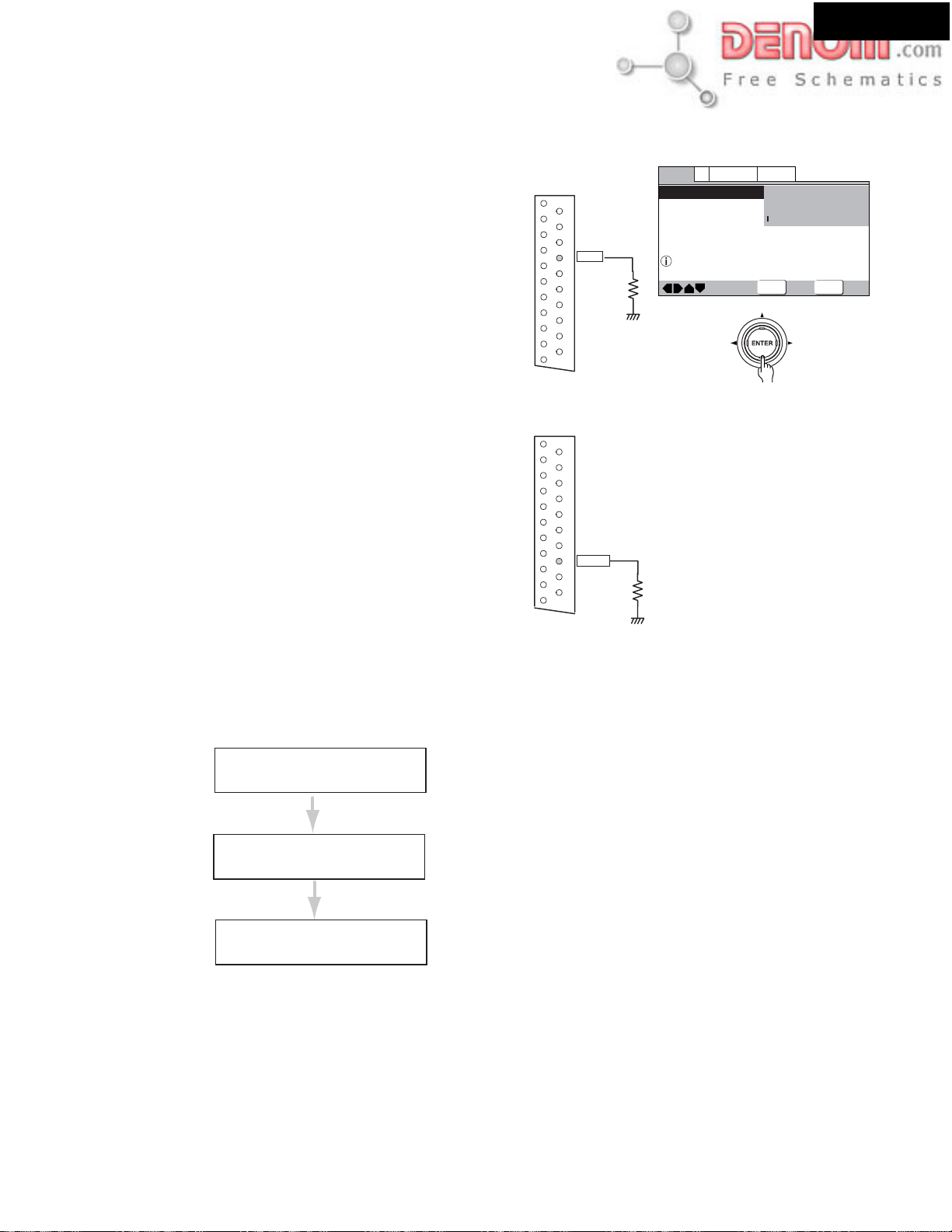
7. The control voltage of AV connector (UPP type only)
DR-S2.2
1. FSW voltage.
1. Connect a dummyload, 10 kohms to No.8 pin of AV connector.
2. Play a DVD disk of 16:9 aspect ratio (width-old-heigt-ratio).
3. Go into setup menu.
Check No.8 pin voltage as changing aspect ratio in TV Screen
of Video 1.
4 : 3 -------- from 9.5 to 12 V DC
16 :9 -------- from 5 to 8 V DC
2. RGB switching voltage
1. Connect the dummy load, 75 ohms to the No.16 pin of
AV connector.
2. Change video mode with setup menu.
Check No.16 pin voltage as changing Video Mode in SETUP menu
Video/S-Video ----- 0.4V DC max.
RGB ----- 1.0V DC min.
P1801
AV CONNECTOR
P1801
AV CONNECTOR
AUDIO_R
1
NC1
2
AUDIO_L
3
AGND
4
VGND1
5
NC2
6
RGB_B
7
FSW
8
9
VGND2
10
NC3
11
RGB_G
12
NC4
13
VGND3
14
VGND4
15
RGB_R/C
16
RGBSW
17
VGND5
18
VGND6
19
CV/Y
20
NC5
21
VGND7
AUDIO_R
1
NC1
2
AUDIO_L
3
AGND
4
VGND1
5
NC2
6
RGB_B
7
FSW
8
VGND2
9
NC3
10
RGB_G
11
NC4
12
VGND3
13
VGND4
14
RGB_R/C
15
RGBSW
16
17
VGND5
18
VGND6
19
CV/Y
20
NC5
21
VGND7
Video1
Language
V2
TV Screen
Component Video
General
4:3(Letter Box)
4:3(Pan&Scan)
16:9(Wide)
Select your display preference
Move
ENTER
Select
SETUP
Exit
SPECIAL OPERATION
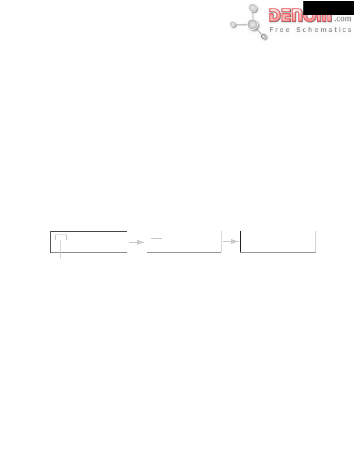
1. How to check the program version of microprocessor
1. Press STANDBY/ON while pressing down SUBWOOFER MODE in POWER ON.
[Example]
FL display
1733-02118A
Sub 01Y16A
NO DISC
2. How to check the version of DVD firmware
Refer to "UPGRADE FIRMWARE-4"
Caution: After adjustment, lock all adjusted screws with screw tightening agent
Program Version of main microprocessor (Q8001).
It displays for 3 seconds.
Program Version of sub microprocessor (Q7002).
It displays for 2 seconds.
Check mode finishes automatically.
www.denom.com
Page 15
ADJUSTMENT PROCEDURES-4
Page 15
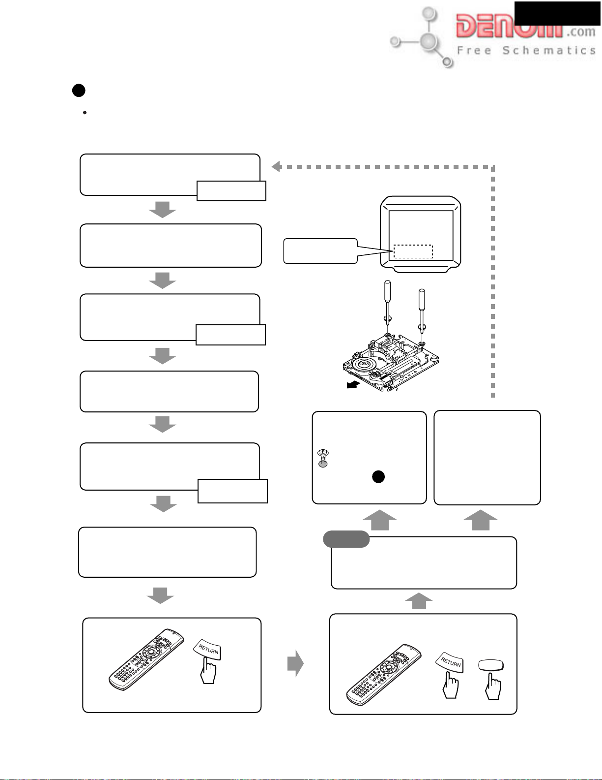
ADJUSTMENT OF DVD MECHANISM-1
1. Adjustment items and location
Adjustment Items
[Mechanism Part]
Tangential and Radial Height Coarse Adjustment
1
2
DVD Jitter Adjustment
3
How to initialize the Focus Sweep Setting
[Electrical Part]
Electrical adjustments are not required.
Adjustment Points (Mechanism Part)
Cautions:After adjustment, lock all adjusted screws with screw
tightening agent.
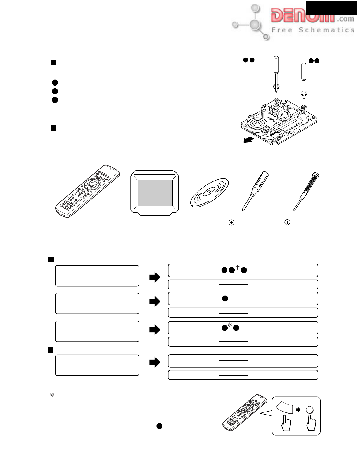
2. JIGS and measuring instruments
1
Tangential
adjustment
screw
Front side
DR-S2.2
2
2
1
Radial
adjustment
screw
Remote controller
RC-484M
Part No. 24140484
3. Necessary adjustment points
When Adjustment Points
Exchange Parts of Mechanism Assy Parts
Pickup
Traverse Mechanism
Spindle Motor
Exchange of PCB Assy
Exchange PC Board
SSIB, LOAB, DVDM ASSY
TV monitor
DVD test disc
(GGV1025)
Mechanical point
Electric point
Mechanical point
Electric point
Mechanical point
Electric point
Mechanical point
Electric point
Screwdriver (medium)
1 2 3
3
2 3
Precise screwdriver
After adjustment, screw locks
with the Screw tight.
After adjustment, screw locks
with the Screw tight.
After adjustment, screw locks
with the Screw tight.
After adjustment, screw locks
with the Screw tight.
Purpose: To adjust individual Traverse Mechanism
to it best sweep.
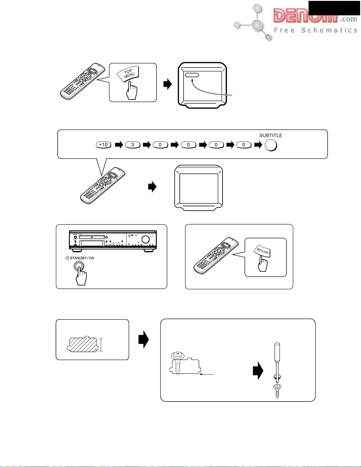
When you replace Pickup, Traverse Mechanism or Spindle Motor
press RETURN and then press CLEAR at the last stage.
(It is necessary when you performed procedure adjustment.)
2
www.denom.com
Remote controller
RC-484M
Part No. 24140484
RETURN
CLEAR
Page 16

ADJUSTMENT PROCEDURES-5
Page 16
ADJUSTMENT OF DVD MECHANISM-2
DR-S2.2
4. Connection
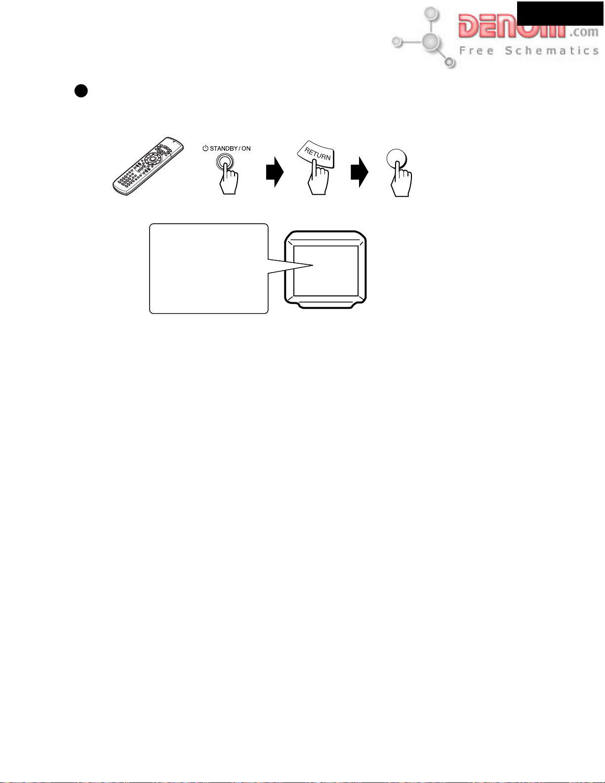
5. T est mode
SETTING REMOTE CONTROLER
TEST MODE: ON
ANTENNA
AM
FM
75
+
DVD
Press 1 as holding down DVD.
Remote controller
RC-484M
Part No. 24140484
MON
OUT
OUT
VIDEO
OUT
SUB
WOOFER
PRE OUT
AUDIO
MON
OUT
REMOTE
CONTROL
MON
2 ––VIDEO–– 1 VIDEO 2 VIDEO 1
OUT
OUT
IN
IN
IN OUT INININ
VIDEO 1 TAPE
VIDEO2
MD/HD
CDR/PC
DIGITAL INPUT
COMPONENT VIDEO OUTPUT
VIDEO 2 VIDEO 1
DIGITAL
OUTPUT
IN IN
OPT
OPT
S VIDEO
FRONT SPEAKERS
L
AUDIO
R
TV/LINE
P
B
P
R
Y
COAX
SURROUND
CENTER
SPEAKERS
SPEAKER
BA
L
RLR
R
L
ON
TEST MODE: DISC SET
Tray open
DVD disc
Tray close
Check
DSC-DVD
DSC -
www.denom.com
Page 17
ADJUSTMENT PROCEDURES-6
Page 17
ADJUSTMENT OF DVD MECHANISM-3
TEST MODE: PLAY
< When playback with the target address of disc (DVD)>
For example, when playback with # 30000
DR-S2.2
An address is displayed
During PLAY
030000
TEST MODE: OFF
OR
OFF
Tangential and Radial Height Coarse Adjustment
Press keys in order
Spacer
7.3mm
Put a spacer between a Tangential (or Radial) adjustment
screw and Mechanism Base and turn each screw to adjust
the height. (Refer to " 1.Adjustment items and location)
LOCATION".)
Turn a flat side
into bottom
www.denom.com
Page 18
ADJUSTMENT PROCEDURES-7
Page 18
ADJUSTMENT OF DVD MECHANISM-4
2
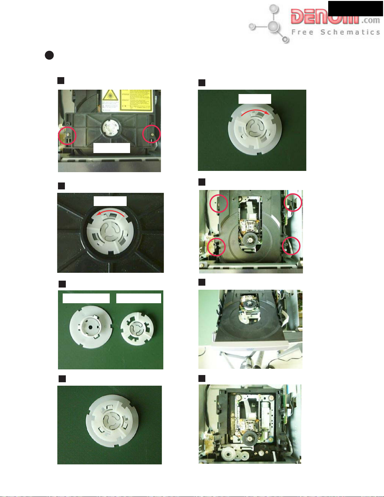
DVD jitter Adjustment
Preparation of adjustment
Remove table(disc) in order to adjustment Tangential screw and Radial screw.
Remove two screws.
1
And remove clamper ass'y from mechanism.
clamper ass'y
Remove Disc(clamper) and Disc(holder).
2
5
Lock
Remove four screws.
6
And remove DVD Mechanism from chasis.
DR-S2.2
Unlock
3
Disc (clamper)
Asembling Disc(clamper) and Disc(holder).
4
Disc (holder)
7
Pull out Table (disc)
Atttach DVD Mechanism to Chasis.
8
www.denom.com
Page 19
ADJUSTMENT PROCEDURES-8
Page 19
ADJUSTMENT OF DVD MECHANISM-5
2
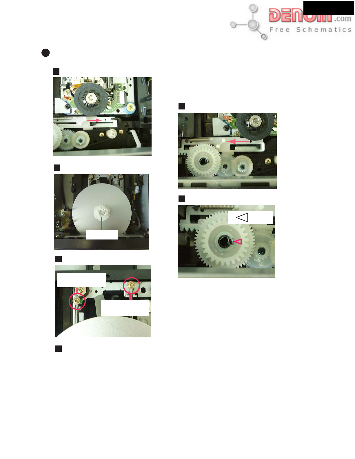
DVD jitter Adjustment
DR-S2.2
Move slider to the arrow direction.
9
Set the test disk and the Disc(cramper).
10
After adjustment
After you complete sdjustment attach Table(disc) in
reverce procedure.
Take care to re-assemble the procedure.
The position of the gear
Move slider to arrow.
1
The position of the gear is as follows.
2
Mark
Cramper
View of Adjustment screws.
11
Tangential
adjustment screw
Radial
adjustment screw
Refer to the next page
12
(ADJUSTMENT PROCEDURES-9)
www.denom.com
Page 20
ADJUSTMENT PROCEDURES-9
Page 20
ADJUSTMENT OF DVD MECHANISM-6
2
DVD Jitter Adjustment
Playback method of inner and outer address for the purpose is refererd to "5. TEST MODE".
Use disc: GGV1025
Test mode
Play the DVD test disc at outer track
(around #200000)
Mechanism Assy
Adjust the Tangential Adjustment Screw
so that jitter becomes minimum.
J4 : Min
J4 :
DR-S2.2
Monitor
J4 : - - - -
Test mode
Play the DVD test disc at innerouter track
(around #30000)
J4 : Min
Mechanism Assy
Adjust the Radial Adjustment Screw so that
jitter becomes minimum.
Test mode
Play the DVD test disc at outer track
(around #200000)
J4 : Min
Mechanism Assy
Adjust the Tangential Adjustment Screw
so that jitter becomes minimum.
Tangential
adjustment
screw
Front side
If error rate is OK,
locks a root of
tangential and radial
adjustment screws with
the Screw tight, and
go to step
Screw tight : GYL1001
3
OK NG
Check
Confirm the error rate that is
displayed "OK"
(Example ER (av): 2.5e - 5-*OK )
Radial
adjustment
screw
Turn the POWER OFF in
case of NG once, and
perform the adjustment
once again.
Test mode end
www.denom.com
Disc playback normally.
•
The measurement of block error rate
5
Page 21
ADJUSTMENT PROCEDURES-10
Page 21
ADJUSTMENT OF DVD MECHANISM-7
Initialize the Focus Sweep Setting
3
Purpose: To set the sweep which was correct with the individual Traverse mechanism.
DR-S2.2
RC-484M
ON
CLEAR
Monitor
Memory Clear!!!
PL Region : X1
ROM Vertion : 1.128
Note: Be sure to perform this step when replaced the Pickup or Traverse mechanism.
www.denom.com
Page 22
ADJUSTMENT PROCEDURES-11
Page 22
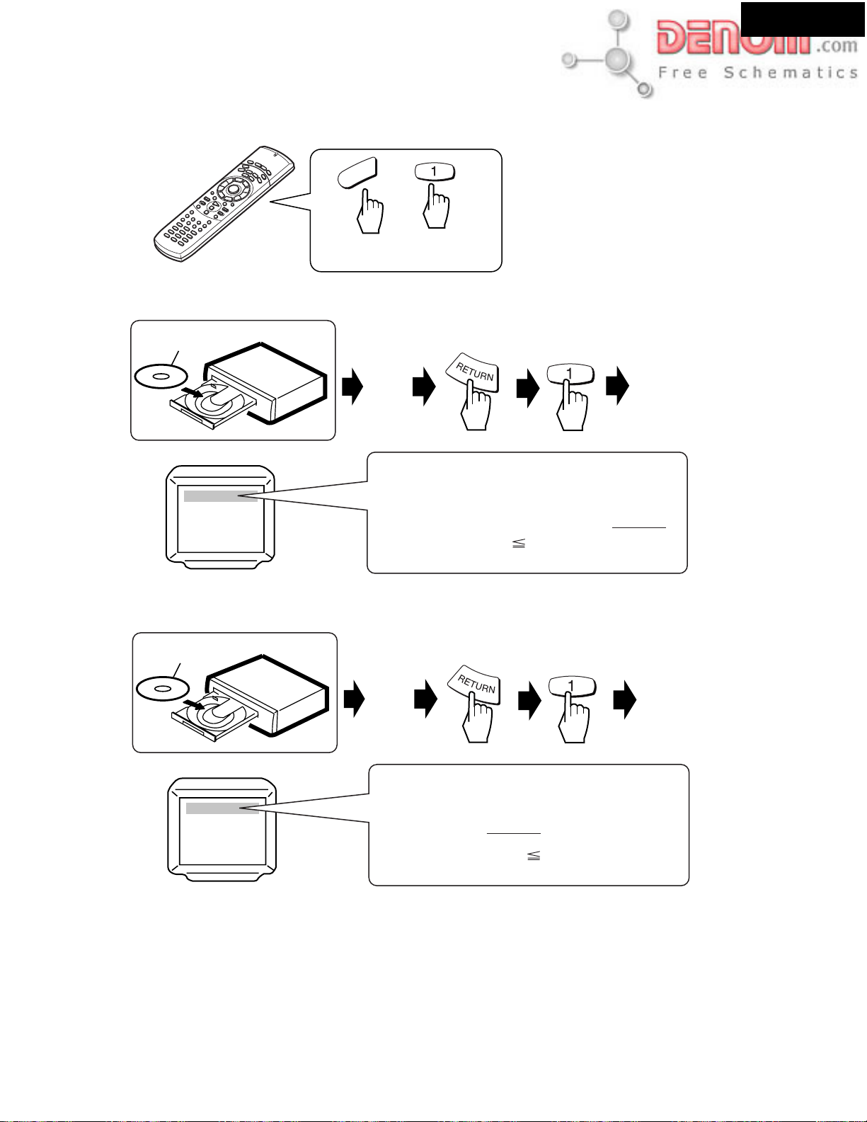
CHECK THE ERROR RATE
Setting remote controller
DVD
Press the hold down DVD button,
then press 1 button.
Check the CD error rate
CD test disc
DR-S2.2
+
Check the DVD error rate
DVD test disc
Play
[Exanple]
ER C1 33
CD error rate = 33 / (7.35 x 5 x 1000) = 0.9 x 10
SPEC : CD error rate 3.26 x 10
Play
-6
[Exanple]
ER(av) : 4.7e-5 * OK
DVD error rate = 4.7 x 10
SPEC : DVD error rate 8 x 10
-5
-4
Waiting for 8 seconds
-3
Waiting for 15 seconds
www.denom.com
Page 23
DR-S2.2
Page 23
A201
A061
DR-S2.2
A012
A208
A332
A335
A065
A012
U23
A012
A012
A306
A012
A039
A203
A036
Z706
A031
U8
Z705
U7
Z704
Z703
(Black)
U6
P8002
P1002
A111
A038
A012
U30
A203
Z702
Z700
(Blue)
A111
P0003
U1
A206
A014
P0005
P0006
A017
A012
P7001
P0004
Z708
A012
A205
A012
A091
Z701
Z707
U12
A028
A012
A078
A080
A015
A094
U10
A085
A021
A070
U3
A111
A012
U17
A068
A101
A012
A001
A100
A335
A104
U5
A111
F9921
A331
A057
A041
A018
U11
A008
A009
A055
A012
A012
A049
P8401
U26
P1802
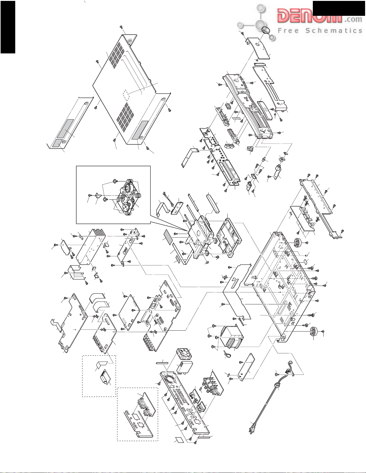
PP2P type only
EXPLODED VIEW
U14
U13
A034
A048
A305
U31
A304
U29
A111
DD1N type only
A307
E882
U16
A047
A871
U15
U4
A301
A047
E702
F9991
A012
A305
A022
T991
A005
U2
A051
P991
A010
A002
A005
www.denom.com
Page 24
DR-S2.2
Page 24
DR-S2.2
REMARKS
PART NO.
82143010
27141781
838430088
28184800A
DESCRIPTION
3P+10FN(BC)
(HP)
3TTB+8B(BC)
NAME
Pan head screw
Retainer
Taping screw
Top cover
REF NO.
A101
A104
A111
A201
29362760A
28148464
28175286
(PATENT)
(TRAY)
Label
Door
Isolated plate
A203
A205
A206
DD1N
PP2P
28326000
27122950A
27122951A
(VOL)AS
UDD1N
UPP2P
Knob
Rear panel
Rear panel
A208
A301
A301
DT3P, PT3P, GK3P
PA4P
GR6P
DS4P
27122960A
27122961A
27122962A
27122991A
833450102
UDT/PT/GK3P
UDS4P/UPA4P
UGR6P
UDS4P
5STP+10BQ(BC)
Rear panel
Rear panel
Rear panel
Rear panel
Special screw
A301
A301
A301
A301
A304
DD1N
DT3P
28141447
29362938
29363062
(UD)
UDT3P/UDS4P
Cushion
Label
Specification label
A305
A306
A307
PT3P
GK3P
PA4P
DD1N, DT3P, DS4P
29363063
29363064
29363065
27212374
UPT3P
UGK3P
UPA4P
(A)UDD
Specification label
Specification label
Specification label
Front panel
A331
PP2P, PT3P, GK3P, PA4P, GR6P
DD1N
PP2P
27212375
27212376
27212377
(A)UPP
(B)UDD
(B)UPP
Front panel
Front panel
Front panel
A332
DT3, PT3P, GK3P, PA4P, GR6P
DS4P
27212381
27212405
28198918
(B)UDT
(B)UDS
(1P)
Front panel
Front panel
Facet
A335
PP2P, PT3P, GK3P, PA4P, GR6P
880009
29110167
260208
24502315
P-RIVET NRP-345
(CU)UL9A0624F403
Rivet
Tape
Wire tie
Cooling fan
[NOTES]
A871
A094
E702
E882
UPA4P: Australian area (Regional code-4)
UDS4P: South America area (Regional code-4)
UGR6P: Chinese area (Regional code-6)
UDD1N: North American area (Regional code-1)
UPP2P: European area (Regional code-2)
UGK3P: Korean area (Regional code-3)
UDT3P: Some Asian area (AC 230V, Regional code-3)
UPT3P: Some Asian area (AC 120V, Regional code-3)
EXPLODED VIEW PARTS LIST-1
REMARKS
PART NO.
27100417
27175392
831430088
27190511
DESCRIPTION
(AS)
3TTW+8B(BC)
KGLS-16RF
NAME
Chassis
Bottom leg
Taping screw
Holder
REF NO.
A001
A002
A005
A008
27190657
27191128
838130088
29362648
KGLS-18RF
KGPS-18RF
3TTB+8B
(DVD2)
Holder
Holder
Taping screw
Label
A009
A010
A012
A014
27190926
29110083
29362541
(DVD)
(CROSS-16U)
(BTM)
Holder
Tape
Label
A015
A017
A018
27130878
27255004
27190009
27160498A
838430167
27141805
(L)
CS-1U
KGLS-4S
RAD-163
3TTB+16S(BC)
(S)
Bracket
Clip
Holder
Heat sink
Taping screw
Retainer
A021
A022
A028
A031
A034
A036
www.denom.com
27130858
27141780
28330135A
(H)
(HD)
(SCREW)
Bracket
Retainer
Cap
A038
A039
A041
830440069
27190470
27190062
27300750
4TTC+6C(BC)
KGLS-18S
KGLS-12S
S-RELIEF #2271
Taping screw
Holder
Holder
Bushing
A047
A048
A049
A051
27130862B
27190011
27111187C
(F)
KGLS-6S
(AS)
Bracket
Holder
Front bracket
A055
A057
A061
28198951
28191959
28325874A
(LIGHT)
DR-S2.2
(POW)AS
Facet
Clear plate
Knob
A065
A068
A070
28191907
28325878
28325880A
(RE)
(INP-1)AS
(INP-2)AS
Clear plate
Knob
Knob
A078
A080
A085
PP2P, PT3P, GK3P, PA4P, GR6P
28325882
28325868
(INP-3)AS
(POW)
Knob
Knob
A091
A100
NOTE: THE COMPONENTS IDENTIFIED BY MARK ARE
CRITICAL FOR RISK OF FIRE AND ELECTRIC SHOCK.
REPLACE ONLY WITH PART NUMBER SPECIFIED.
Page 25

DR-S2.2
Page 25
REMARKS
DD1N, DS4P
PP2P, PT3P, PA4P
GK3P, GR6P
DT3P
PART NO.
1H487528-1A
1H487528-1B
1H487528-1C
1H487528-1D
DESCRIPTION
NAAR-7428-1A
NAAR-7428-1B
NAAR-7428-1C
NAAR-7428-1D
DD1N, DS4P
PP2P, PT3P, PA4P
GK3P, GR6P
DT3P
1H487529-1A
1H487529-1B
1H487529-1C
1H487529-1D
NAPS-7429-1A
NAPS-7429-1B
NAPS-7429-1C
NAPS-7429-1D
DD1N, DS4P
PP2P, PT3P, PA4P
GK3P, GR6P
DT3P
1H487530-1A
1H487530-1B
1H487530-1C
1H487530-1D
NASW-7430-1A
NASW-7430-1B
NASW-7430-1C
NASW-7430-1D
PP2P, PT3P, PA4P
GK3P, GR6P
DT3P
DD1N, DS4P
PP2P, PT3P, PA4P
1H487531-1B
1H487531-1C
1H487531-1D
1H4875232-1A
1H4875232-1B
NAAF-7431-1B
NAAF-7431-1C
NAAF-7431-1D
NAETC-7432-1A
NAETC-7432-1B
GK3P, GR6P
DT3P
DD1N, DS4P
PP2P, PT3P, PA4P
GK3P, GR6P
1H4875232-1C
1H4875232-1D
1H487533-1A
1H487533-1B
1H487533-1C
NAETC-7432-1C
NAETC-7432-1D
NAETC-7433-1A
NAETC-7433-1B
NAETC-7433-1C
DT3P
DD1N, DS4P
PP2P, PT3P, PA4P
GK3P, GR6P
DT3P
1H487533-1D
1H487534-1A
1H487534-1B
1H487534-1C
1H487534-1D
NAETC-7433-1D
NAETC-7434-1A
NAETC-7434-1B
NAETC-7434-1C
NAETC-7434-1D
DD1N
PP2P
PT3P, GK3P, PA4P, GR6P
DT3P, DS4P
1H487535-1A
1H487536-1A
1H487536-1B
1H487536-1C
1H487536-1D
NAETC-7435-1A
NADIS-7436-1A
NADIS-7436-1B
NADIS-7436-1C
NADIS-7436-1D
DR-S2.2
UPA4P: Australian area (Regional code-4)
UDS4P: South America area (Regional code-4)
UGR6P: Chinese area (Regional code-6)
NAME
Main PC board ass'y
Main PC board ass'y
Main PC board ass'y
Main PC board ass'y
Power supply (primary) PC board ass'y
REF NO.U1U2
REMARKS
PP2P, PT3P, GK3P, PA4P, GR6P
DD1N, DT3P, DS4P
PP2P, PT3P, GK3P, PA4P, GR6P
DD1N CDT3P, DS4P
PART NO.
252077
252163
252071
252162
2045172012
DESCRIPTION
4A-SE-EAK
4A-UL/T-237
1.6A-SE-EAWK
3.15A-UL/T-237
NCFC5-172012
Power supply (primary) PC board ass'y
Power supply (primary) PC board ass'y
Power supply (primary) PC board ass'y
Power switch PC board ass'y
Power switch PC board ass'y
Power switch PC board ass'y
Power switch PC board ass'y
Speaker terminal PC board ass'y
Speaker terminal PC board ass'y
Speaker terminal PC board ass'y
Head phone terminal PC board ass'y
Head phone terminal PC board ass'y
U3
PP2P
2046061012
20022391015
204D26002HIT
2047291012
2045131012
NCFC6-061012
NSAS-10P1025
NCFCD-26002
NCFC7-291012
NCFC5-131012
U4
PP2P, PT3P
PP2P, PT3P
2045161512
2047251012
2047151012
253237HIT or
253314HRK
NCFC5-161512
NCFC7-251012
NCFC7-151012
AS-CEE or
AS-CEE
U5
GK3P
GR6P
253246KAW
253287HIT or
AS-CEE-2
AS-CCEE or
Head phone terminal PC board ass'y
Head phone terminal PC board ass'y
Regulator IC PC board ass'y
Regulator IC PC board ass'y
Regulator IC PC board ass'y
Regulator IC PC board ass'y
Thermal detection PC board ass'y
Thermal detection PC board ass'y
Thermal detection PC board ass'y
Thermal detection PC board ass'y
Holder PC board ass'y
Display PC board ass'y
U6
GR6P
DD1N, DT3P, DS4P
PA4P
253288VOL
253294HDK
253315HRK
AS-CCEE
AS-UC-2#18
AS-SAA
DD1N, DT3P, DS4P
2301580
NPT-1437D
U7
PP2P, PT3P, PA4P
GK3P, GR6P
2301581
2301582
24801013
NPT-1437P
NPT-1437G
DB-VTV301
U8
24801014
24818049
DT1300AB
U10
Display PC board ass'y
Display PC board ass'y
Display PC board ass'y
24818050
801589
24822043
838426088
801590
24834041
(A)
2.6TTB+8B(BC)
(B)
(C)
[NOTES]
UDD1N: North American area (Regional code-1)
UPP2P: European area (Regional code-2)
UGK3P: Korean area (Regional code-3)
UDT3P: Some Asian area (AC 230V, Regional code-3)
UPT3P: Some Asian area (AC 120V, Regional code-3)
EXPLODED VIEW PARTS LIST-2
NAME
FUSE
FUSE
REF NO.
F9921
FUSE
FUSE
Flexible flat cable
F9991
P003
Flexible flat cable
SOCKET AS
Flexible flat cable
Flexible flat cable
Flexible flat cable
P004
P005
P006
P102
P1802
Flexible flat cable
Flexible flat cable
Flexible flat cable
Power supply cord
Power supply cord
P7001
P8002
P8401
P991
www.denom.com
Power supply cord
Power supply cord
Power supply cord
Power supply cord
Power supply cord
Power transformer
Power transformer
Power transformer
DVD mechanism
(traverse unit)
T991
T991
T991
Z700
DVD mechanism
(DVD tray loading mehcanism)
Insulator
Insulator
Special screw
Retainer
Self taping screw
Special screw
Z701
Z702
Z703
Z704
Z705
Z706
Z707
Washer
Z708
NOTE: THE COMPONENTS IDENTIFIED BY MARK ARE
CRITICAL FOR RISK OF FIRE AND ELECTRIC SHOCK.
REPLACE ONLY WITH PART NUMBER SPECIFIED.
Page 26
DR-S2.2
Page 26
DR-S2.2
UPA4P: Australian area (Regional code-4)
UDS4P: South America area (Regional code-4)
UGR6P: Chinese area (Regional code-6)
REMARKS
DD1N
PP2P
PT3P, GK3P, PA4P, GR6P
DT3P, DS4P
DD1N
PP2P
PT3P, GK3P, PA4P, GR6P
DT3P, DS4P
DD1N
PP2P
PT3P, GK3P, PA4P, GR6P
PART NO.
1H487537-1A
1H487537-1B
1H487537-1C
1H487537-1D
1H487538-1A
1H487538-1B
1H487538-1C
1H487538-1D
1H487539-1A
1H487539-1B
1H487539-1C
DESCRIPTION
NAPS-7437-1A
NAPS-7437-1B
NAPS-7437-1C
NAPS-7437-1D
NASW-7438-1A
NASW-7438-1B
NASW-7438-1C
NASW-7438-1D
NAVD-7439-1A
NAVD-7439-1B
NAVD-7439-1C
NAME
Power supply (Secondary) PC board ass'y
Power supply (Secondary) PC board ass'y
Power supply (Secondary) PC board ass'y
Power supply (Secondary) PC board ass'y
Operation switch PC board ass'y
Operation switch PC board ass'y
Operation switch PC board ass'y
Operation switch PC board ass'y
Video PC board ass'y
Video PC board ass'y
Video PC board ass'y
DT3P, DS4P
PP2P
DD1N
PT3P, GK3P, PA4P, GR6P
DT3P, DS4P
DD1N
PP2P
PT3P, GK3P, PA4P, GR6P
DT3P, DS4P
1H487539-1D
1H487540-1B
1H487541-1A
1H487541-1C
1H487541-1D
1H487542-1A
1H487542-1B
1H487542-1C
1H487542-1D
NAVD-7439-1D
NAVD-7440-1B
NAVD-7441-1A
NAVD-7441-1C
NAVD-7441-1D
NAETC-7442-1A
NAETC-7442-1B
NAETC-7442-1C
NAETC-7442-1D
Video PC board ass'y
AV connector PC board ass'y
Component terminal PC board ass'y
Component terminal PC board ass'y
Component terminal PC board ass'y
Digital terminal PC board ass'y
Digital terminal PC board ass'y
Digital terminal PC board ass'y
Digital terminal PC board ass'y
DD1N
PP2P
PT3P, GK3P, PA4P, GR6P
DT3P, DS4P
DD1N
PP2P
1H487543-1A
1H487549-1A
1H487549-1B
1H487549-1C
1H487549-1D
1H487552-1A
1H487552-1B
NAETC-7443-1A
NAETC-7449-1A
NAETC-7449-1B
NAETC-7449-1C
NAETC-7449-1D
NADG-7452-1A
NADG-7452-1B
Holder PC board ass'y
Regulator IC PC board ass'y
Regulator IC PC board ass'y
Regulator IC PC board ass'y
Regulator IC PC board ass'y
DSP and Microprocessor PC board ass'y
DSP and Microprocessor PC board ass'y
DS4P
PA4P
DT3P, PT3P, GK3P, R6P
DD1N, DS4P
PP2P, DT3P, PT3P, GK3P, DS4P, PA4P CGR6P
DD1N
DD1N, DS4P
DD1N, DS4P
PP2P, DT3P, PT3P, GK3P, GR6P
PP2P, DT3P, PT3P, GK3P, GR6P
[NOTES]
UDD1N: North American area (Regional code-1)
1H487552-1C
1H487552-1D
1H487552-1E
1H487510-1A
24150026
24150027
240134A or
240141
240135 or
240142
NADG-7452-1C
NADG-7452-1D
NADG-7452-1E
NAAF-7510-1A
DB-VPB303A
DB-VPB304
TFCE1U114B or
FAE350-A13F
TFCE1E512A or
FAE404-E13F
DSP and Microprocessor PC board ass'y
DSP and Microprocessor PC board ass'y
DSP and Microprocessor PC board ass'y
Speaker terminal PC board ass'y
DVD Main PC board ass'y
DVD Main PC board ass'y
Tuner unit
Tuner unit
Tuner unit
Tuner unit
UPP2P: European area (Regional code-2)
UGK3P: Korean area (Regional code-3)
UDT3P: Some Asian area (AC 230V, Regional code-3)
UPT3P: Some Asian area (AC 120V, Regional code-3)
EXPLODED VIEW PARTS LIST-3
REF NO.
U11
U12
U13
U14
U15
U16
www.denom.com
U17
U23
U26
U29
U30
U31
NOTE: THE COMPONENTS IDENTIFIED BY MARK ARE
CRITICAL FOR RISK OF FIRE AND ELECTRIC SHOCK.
REPLACE ONLY WITH PART NUMBER SPECIFIED.
Page 27
EXPLODED VIEWS OF MECHANISM
Page 27
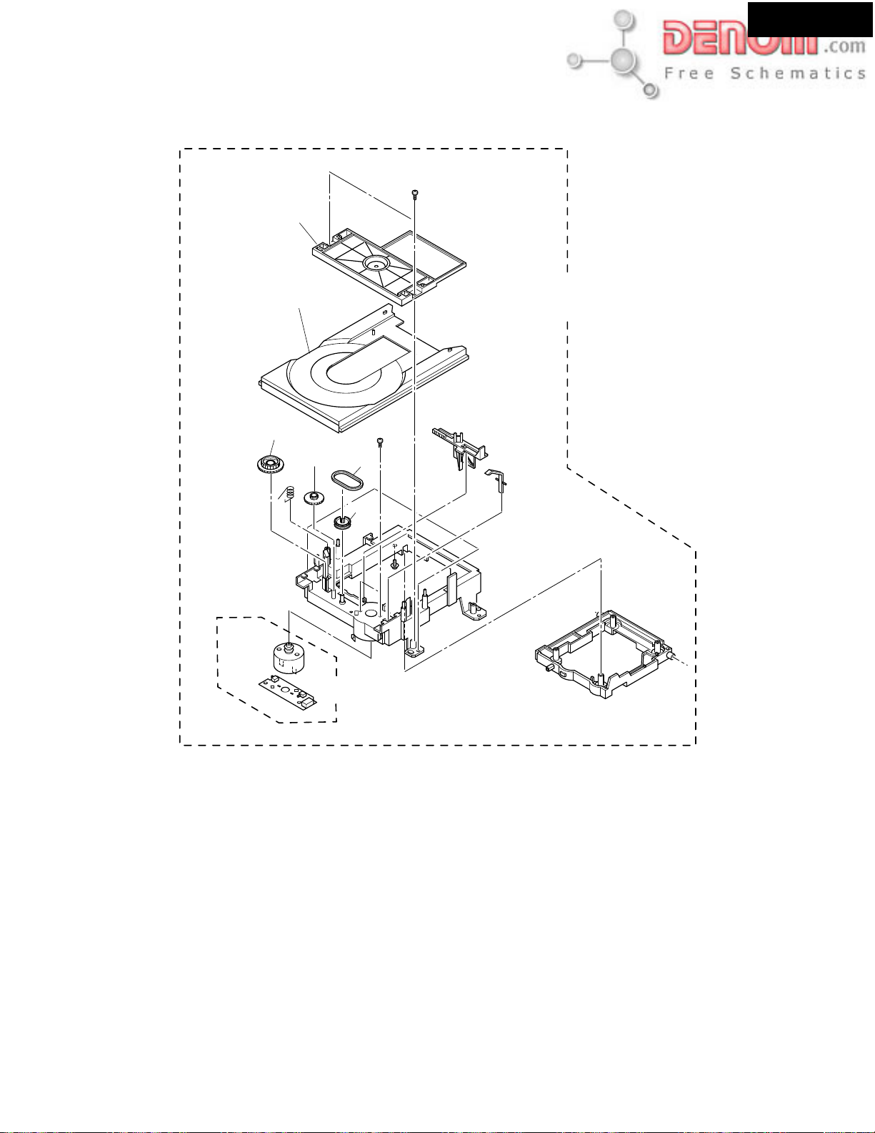
DVD TRAY LOADING MECHANISM : DT1300
B22
DR-S2.2
B21
B19
DT1300
Part No.24801014
B18 B17
B16
B13
PARTS LIST
REF NO.
B13
B16
B17
B18
B19
B21
B22
PART NO.
70300470B
70333502B
70342118
70333503C
70333504D
70366204
70300615
DESCRIPTION
LOADING MOTOR AS
PULLEY, GEAR
BELT
GEAR, LOADING
GEAR, CONNECTOR
TABLE DISK-B DVD
CLAMPER AS B
www.denom.com
Page 28

EXPLODED VIEWS OF MECHANISM
Page 28
TRAVERSE UNIT: DB-VTV301
18
18
(Torque : 0.12 0.01 N m)
17
12
8
3
DR-S2.2
18
13
10
1
16
10
7
14
6
19
(Adjustment
4
screw)
(Adjustment
4
screw)
5
5
Screw tight
(Torque : 0.12 0.01 N m)
17
16
17
15
9
(Torque : 0.12 0.01 N m)
2
11
PARTS LIST
REF NO. DESCRIPTION PART NO.
1 Spindle Motor VXM1088
(or VXM1089)
2 Stepping Motor VXM1090
(CARRIAGE) (or VXM1091)
3 Pickup Assy-S OXX8003
4 Skew Screw VBA1080
5 Skew Spring VBH1335
6 Guide Bar VLL1514
7 Sub Guide Bar VLL1515
8 Hold Spring VNC1017
The mechanical parts with no part number
in the exploded views are not supplied.
REF NO. DESCRIPTION PART NO.
9 Joint Spring VNC1019
10 Support Spring VNC1020
11 Mechanism Chassis --12 Slider VNL1811
13 Spacer VNL1913
14 Joint VNL1914
15 FFC Holder VNL1915
16 Screw BBZ20P050FZK
17 Screw OBA8009
18 Screw PMA26P100FMC
19 Damper Sheet VEB1335
www.denom.com
Page 29

DISPLAY
D7006
3
K
B
PC
AD
E
DR-S2.2
Page 29
A
SCHEMATIC DIAGRAMS-1
DISPLAY SECTION
1
NP
NP
1G5
2G6
F1A1
F1B2
2
F1
F2
+5V
-VB
3
3G74G8
3
4
1G2G3G4G5G6G7G8G9G
14G P30
13G P31
12G P32
11G P33
10G P34
9G P35
8G P36
7G
6G
5G
4G
3G
2G
1G
CST5.00MGW
1M
R7004
BCD
Q7001
14-BT-74GNK
5G9
P5 P24
P4 P25
P3 P26
P2 P27
P1 P28
X7001
6G107G11
8G129G13
61
10G1411G15
10G
11G
0
R7005
P5
P462
P363
P264
P165
NC66
14G67
13G68
12G69
11G70
10G71
9G72
8G73
7G74
6G75
5G76
4G77
3G78
2G79
1G80
12G16
13G17
14G18
NC
NC
NC
NC
P123
22
21
20
19
12G
13G
14G
P1P2P3P4P5
P6P7P8
P9
P10
P11
P12
P13
59
60
P6 58
P7 57
P8 56
P9 55RESET6
P1054
P1153
VDD2
VLOAD
P1252
Q7002
MPD780232GC-066-8BT
SUBCK7
SUBDI9
SUBDO8
GND15
VDD1
VSS12X14X2
1
3
P1032
P1133
P224
P325
P426
P527
P628
P729P830
P6P7P8
P14
P15
P16
P17
P18
P19
P1351
P1450
P1549
P1648
P1747
P1846
SUBRDY10
VAJ12
VBJ11
/IRIN15
/SYSIN13
/SYSOUT14
P1234P1335P1436
P931
P10
P11
P12
P13
P21
P22
P2143
LED2 27
LED3 26
VDD0 25
VSS0 23
GND218
P23
P24
P2242
P2341
P25 39
P26 38
P27 37
P28 36
P29 35
P30 34
P31 33
P32 32
P33 31
P34 30
P35 29
P36 28
+5V 24
K0
K1
K220
K319
40
22
21
P14
P9
P20
P1945
P2044
LED017
LED116
P1537
P15
P1638
P16
P17
P29
P1739
P18
P1840
P19
41
P19
P20
R70162.7K
R7015 2.7K
R7017
N
NP
NP
F2A61
P2042
P2143
P2244P2345
P2446
P2547
P2648
P2749
P2850
P2951
P3052
P3153
P3254
P3355
P3456P3557
F2B
P3658
60
59
62
U10
P21
P22
P23
P24
P25
P26
P27
P28
P29
P30
P31
D7004, D7005
FRONT PANEL ILLUMINATION
Q7004
RN1407
104
C7015
2.7K
P32
P33
180
R7019
RN1407
P34
P35
P36
Q7005
D7004
LB3333
180
R7021
EJECT
STANDBY/ON
DISPLAY
D7005
LB3333
INPUT_UP
STAND
Q7006
RN1407
R7023
INPUT_DOWN
STOP
270
R7048
104
10K
R7067
10K
6.5
LEDGND
R7006
0
R7007 0
R7009 0
R7008 0
SUBDI
SUBCK
SUBDO
R7010 0
SUBRDY
RI
390
390
104
104
C7008
C7001
C7003
R7001
R7003
D7001
UDZS4.7B
F1
F2
104
C7006
C7007
D7011
GP104001E
-VB
GND
+5.6V
to NADG-7452
4.9
100/6.3
RESET
+7V
-27.5
-VB
+5V
4
104
C7014
P7001B
NASW-7438
U12
5
OPERATION SWITCH
PC BOARD
R7011 47K
+5V
GND
P7002A
from NADIS-7436
P7002B
RN2403
Q7003
VBJ
VAJ
+5V
LED
GND
RIMO
to NASW-7438
GND
VAJ
+5V
LED
RIMO
VBJ
D7002
1SS352
+5V
+7V
K2
K2
D7003
R7013 220K
R7045 10K
+5V
GND
RIMO
UDZS5.6B
R7044
100
4.7K
R7066
4.7K
R7065
SURROUND
STEREO
S7013
S7014
R7038
R7037
330
R7047
100
S7015
470
C7004
S7019
S7001
R7029
330
S7007 PLAY
330
R7034
SUBWOOFER
MODE
T-D
S7016
R7040
R7039
560
104
C7005
100/6.3
MASTER
VOLUME
S7002
S7003
R7031
R7030
560
470
DOWN
S7009 UP
S7008
560
470
R7036
R7035
ACOUSTIC
CONTROL
S7017
S7018 SPEAKER
R7041
1.2K
820
Q7008
PIC-26043TE2
S7004
R7032
S7010 PRESET
R7046
SETUP
Q7009
RN1407
REMOTE S
S7005
820
S7011FMMUTE
820
R703
1.2
S7006
www.denom.com
Page 30

S7006
DR-S2.2
Page 30
EFGH
DIS-7436
C BOARD
BY/ON
D7006
SEL2110R-TP6
NAVD-7440
PP2P Type only
U14
AV CONNECTOR PC BOARD
P1802B
GND1
BLUE
GND2
GREEN
GND3
CV/Y
GND4
RED/C
FSW
+6V
RGBSW
from NAVD-7439from NAVD-7439
GND5
-6V
-6V
+6V
C1808104
C1807104
C1809
C1805 220/6.3
C1806 220/6.3
4
6
HN1C01F
R1813
C1810
10/16
10/16
0
3
25
1
R1812
R1811
R1810 100
270<0.5W>
47K
D1801 1SS226
4
6
Q1801
HN1C01F
3
25
1
R1809
47K
R1808
10
R1807
<0.5W>
270
C1804
470/6.3
C1803
470/6.3
C1802
470/6.3
C1801
470/6.3
D1802 1SS226
R1804
75
R1803
75
R1802
75
R1801
75
R1805 47K
R1806 47K
L1804
L1803
L1802
L1801
L1805
P1801
AV CONNECTOR
AUDIO_R1
NC12
AUDIO_L3
AGND4
VGND15
NC26
RGB_B7
FSW8
VGND29
NC3
10
RGB_G11
NC4
12
VGND313
14
VGND4
RGB_R/C15
RGBSW
16
VGND517
18
VGND6
CV/Y19
NC5
20
VGND721Q1802
DISPLAY
3
K
+5V
T-D
ENSOR
D7008
270
R7043
SEL2810A-TP2
NAVD-7441
Except PP2P Type
U15
COMPONENT VIDEO PC BOARD
JL1701B
GND
CB/PRGCB
GND
CR/PRGCR
GND
COM_Y/PRGY
to DVD main board
P0004A
to DVD mechanism
INSIDE
V+5S
GNDS
H3H3+
H2H2+
H1H1+
A1
P0003A
A2
A3
ST2-[/B]
ST2+[B]
ST1+[A2]
ST1-[/A]
ST1+[A1]
DUMMY
CLOSE_SW
MOTOR-
OPEN_SW
MOTOR+
SW_GND
L1706
L1705
L1704
C1703
470/6.3
C1702
470/6.3
C1701
470/6.3
INSIDE
V+5VS
GNDS
H3H3+
H2H2+
H1H1+
A1
A2
A3
ST2-[/B]
ST2+[B]
ST1+[A]
ST1-[/A]
SW1
SW2
V+3D
LOADLOAD+
R1708
180
R1703120
L1703
L1702
L1701
R1702
100
R1701
100
470
R1706
470
R1704
560
R1707
560
R1705
BLM21B152
BLM21B152
BLM21B152
NAETC-7453
U27
TERMINAL PC BOARD
P0002A
to DVD mechanism
to DVD mechanism
P0001A
P8009
to DVD main board
P0005A
COMPONENT VIDEO
OUTPUT
P1701
Y
PB
PR
www.denom.com
Page 31

-6
+
27
5R
3
R3048
BO
DR-S2.2
Page 31
A
SCHEMATIC DIAGRAMS-2
AUDIO SECTION (UDD1N TYPE)
TV/LINE
1
TAPE/MD/HD
LEFT
VIDEO1
RIGHT
VIDEO2/CDR/PC
2
SUBWOOFER
PREOUT
3
4
ADATA1
ADATA2
ADATA3
5
C3013
P3001
LEFT
RIGHT
LEFT
IN
RIGHT
LEFT
OUT
RIGHT
C3014
104Z
P3002
IN
LEFT
IN
RIGHT
LEFT
OUT
RIGHT
C3015
P3003
104Z
ADC_L
ADC_R
GND
DAC_R
DAC_L
DAC_RS
DAC_LS
DAC_SW
DAC_C
GND
TO NADG-7452TO DVD MAIN BOARD
TU-L
GND
TU-R
P8701A
VGND
MCLK
BCK
VGND
LRCK
XCSDF0
ADATA0
XSCK
XSI
NC
XMUT
VSEL1
NC
VSEL2
VGND
PRG_CR
VGND
PRG_CB
VGND
PRG_Y
VGND
B/CB
CN15
104Z
G/Y
R/CR
V
C
Y
R3001
330
R3002
330
R3005
330
R3006
330
R3009
2.2K
R3010
2.2K
R3013
330
R3014
330
R3017
330
R3018
330
R3021
2.2K
R3022
2.2K
C3017 47/50
C3018 47/50
C3020 10/16
C3019
C3022 10/16
C3021 10/16
C3024
C3023 10/16
BLM21B222SPT
R4022
47
R402347
R402447
R402547
R402647
R4027
47
R4028
47
R4029
47
R4030
47
R4031
47
R4032
47
R4033
47
R4034
47
R403647
R4037
47
47
R403847R4039
C
R/CR
1M
101J
C3001
R3003
1M
101J
C3002
R3004
1M
101J
C3003
R3007
1M
101J
C3004
R3008
1M
101J
C3005
R3011
1M
101J
C3006
R3012
1M
101J
C3007
R3015
1M
101J
R3016
C3008
1M
101J
C3009
R3019
1M
101J
C3010
R3020
1M
101J
C3011
R3023
1M
101J
C3012
R3024
10/16
47/16
L4002
R402147
L4003
BLM21B222SPT
L4004
BLM21B222SPT
47
R4035
G/Y
B/CB
VGND
VGND
PRG_Y
104Z
473Z
C4020
VGND
VGND
PRG_CB
PRG_CR
TO NAVD-7439
C4015
C4014
100/6.3
C4017
104Z
C4016
100/6.3
C4021
VGND
SQUEEZE
NCH-1471
104Z
LETTER
L4001
022M
SW5V
SW3.3V
VSEL1
VSEL2
BCKIN
1
DATA
2
LRCKIN3MC
GND
4
VDD
5
VCC
6
VOUTL
7
VOUTR
8
+7V
GND
GND
PCM1742KE
Q4001
MCLK
ML
MD
ZEROL
ZEROR
VCOM
AGND
XMUT
D4001
D4002
-7V
SW6V
GND
GND
+12VTUN
BCD
P8002A
C3057
D3003
R3046
270
GND
D3102
D3101
D3001
Q3015
RN2402
R3047
SW12V
SW+5VIN
SW3.3V
SW12V
C3108
10/16
R3050
2.2K
100
SW5V
R9905
+19V
SW3.3V
+5.6V_
IPM
220K
R3109
Q3014
RN1441
220K
R3060
Q99
PQ0
C9934
SW+5VGND
DVDPOWER
6.8
(1W)
C9942
SW2.5V
SW2.5V
VI1VO
2
104Z
VGND
223Z
VGND
DVD_L
DVD_R
8
7
Q3003
NJM4565M
R3054
10K
C3062
330J
C3061
330J
R3053
10K
NJM4565M
Q3003
1
4
220
R4020
16
15
14
13
12
RN1407
11
10
9
C4019
100/6.3
R4019
1K
VCTLA
VCTLB
P1002A
+5VDSP2
R3025
2.2K
R3026
2.2K
Q4007
104Z
C4018
R3102
C3101
R3101
330
Q3103
C3025
10/16
66
65
64
63
62
61
60
59
BASS TREBLE
58
57
56
55
54
53
52
BAAS BOOST
VCC
51
50
VEE
49
MUT
48
CL
47
DA
46
45
44
43
42
41
40
39
C3027
10/16
R4009
33K
C4007
330J
NJM4565M
Q4002
4
C4011
C4012
8
Q4002
NJM4565M
C4008
330J
R4010
33K
RN2402
472J
472J
224J
224J
224J
224J
154J
154J
154J
154J
SELMUT
SELSCLK
SELSDO
C3028
10/16
7
100/16
100/16
1
10/16
R3027
4.7K
R3028
4.7K
R3030
3.3K
R3029
3.3K
C3041
104Z
C3042
100/16
47/16
C4009
47/16
C4010
C3102
C3032
C3031
C3035
C3033
C3036
C3034
C3040
C3038
C3039
C3037
C3043
100/16
C3044
104Z
104Z
100K
100K
R4013
220
R4015
R4016
R4014
220
C3103
SW2.5V
10/16
RN1441
RN1441
Q3102
RN1441
TU-R
TU-L
10/16
C3026
67
BD3811K1
33
31
4.7/50
C3029
C3063
C3064
R4005
15K
102J
C4003
102J
C4004
R4006
15K
7172737475
34
10/16
47/16
47/16
C4005
C4006
69
363738
35
OUT_C
OUT_SW
OUT_LS
R4007
10K
221J
221J
R4008
10K
68
OUT_RS
R4011
R4012
6
5
0
0
3
2
77
78
79
80
76
47k
47k
47k
47k
1
47k
2
47k
3
47k
4
47k
5
47k
6
47k
7
47k
8
47k
9
47k
10
47k
11
47k
12
47k
13
47k
14
47k
15
47k
16
47k
17
18
19
20
47k
21
47k
22
47k
23
47k
24
5
6
2
3
47k
R3052
10K
R3058
2.7K
R3057
150
R3051
10K
47/16
C4001
47/16
C4002
Q3001
47k
47k
47k
297032
30
272625
28
C3030
R3056
150
R3055
2.7K
R4001
2.2K
100K
R4003
100K
R4004
R4002
2.2K
JL9001B
100K
8
5
Q3101
6
4
OUT_R AMP_FR
OUT_L AMP_FL
Q4003
Q4004
C4013
GNDM
SW3.3V
R3103
7
100
NJM4565M
C3050
4.7/50
100K
220K
Q4005
2SA1162
R4018
102J
SW+5VIN
SW+5VGND
47/50
C3046
47/50
C3045
R3041
2.2K
P4006A
P4006B
R4045
R4044
4.7K
10/16
C3104
R3035
R4017
C3105
R3032
470
R3031
470
R3036
470
470
R3039
470
47K
R3042
1.8K
Q4006
RN1407
TO NAPS-7437
NJM4565M
R3106
100K
3
R3104
4.7K
Q3101
2
R3107
220K
C3106
390K
10/16
R3105
101J
RN2402
Q3008
22K
R3034
RN1441
RN1441
22K
R3033
Q3007
22K
R3038
22K
R3037
22K
R3040
R3049
220K
3
Q3012
2
221J
C3051
6.8K
R3043
R3044
C3055
47/16
47/16
C3056
NAAR-7428
U1
U23
NAETC-7449
C9914
CN401
C3107
R3108
1
22
103K
Q3006
NJM4565M
18K
R3045
22K
C3052
330J
6
5
D3002
AMP_RS
AMP_LS
AMP_C
1
4
Q3012
C3053
4.7/50
8
NJM4565M
2.2/50
Q3013
RN1441
7
MAIN PC BOARD
REGULATOR PC
Q9902
PQ12RF1
GND3ON
4VI1VO2
310MA
104Z
C9911
C9912
10/50
JL9003A
JL9003B
Q9905
78M06
IO
G
104Z
10/50
C9913
VGND
VGND
M+6V
M+6V
GNDM
SW5V
TO DVD MAIN BOARD
www.denom.com
Page 32

VO
2
_
VGND
Page 32
M
SPBRL
+5VDSP2
MICONGND
22K
C3054
R3048
TO NADG-7452
AMUT
POWERRL
SPAFRRL
SPACSRL
SELSCLK
SELSDO
222K
DR-S2.2
EFGH
TO NAPS-7429
HPIN
SELMUT
VPRT
IPM
VCTLB
VCTLA
XSOA
XREADY
S[MTOF]
XRESET
XSCLKA
+13V
XLT
JL9991A
+13V
POWERRL
MICONGND
JL5004A
HPIN HPIN
MICONGND
-20V -20V
SPAFRRL SPAFR
GND
SPACSRL SPACS
SPBRL
JL5004B
SWE
SP-B
Q54**
DTA114ES
-20V
C5101
104Z
SWE
SWE
C5102
HPL
HPIN
HPL
HPIN
Q5405
DTA114ES
104Z
HPR
JL5003B
JL5003A
HPR
LGND
(1/2W)
R5061
10
FL_OUT
L5011
LGND
R7602
R7601
S-1.3C
L5012
RGND
FR_OUT
390
(1/2W)
390
(1/2W)
104J
4.7 (1W)
R5071
C5061
104J
4.7(1W)
R5072
C5062
R5101220K
R5102
220K
Q5404
DTA114ES
(1/2W)
R5062
S-1.3C
10
JL5001B
104Z
C7602
P5011
D5401
Q5401
103Z
L7602
L7601
C7601
5101
103Z
R5401
180
(1W)
DTC123JS
220K
R5404
104Z
R5074
4.7
R5073
4.7
NCH-1452_220K
C7603
R7603
0
L7604L7603
SPEAKERSFRONT
A
LRBLR
C5102
RL5401RL5401
R54**
D54**
DTC123JS
Q54**
220K
R5405
C5064
(1W)
104J
C5063
104J
(1W)
R5063
220KNCH-1452
180
(1W)
(1/2W)
10
LS_OUT
L5014
S-1.3C
L5013
S-1.3C
C_OUT
RS_OUT
PHONES
U5
HEAD PHONE TERMINAL
P7601
E7601
PC BOARD
SURROUND
SPEAKER
LRC
103Z
C5103
RL5402
R5403
R5402
180
(1W)
D5402
DTC123JS
Q5402
(1/2W)
R5064
10
R5075
C5065
104J
(1W)
4.7
C5103
104Z
JL5002B
3CHGND
P5012
RL5403
180
(1W)
D5403
DTC123JS
Q5403
CENTER
SPEAKER
SPEAKER
TERMINAL
R5103
PC BOARD
220K
R5104
220K
R5105
220K
NAETC-7432
NAAF-7510
U29
-6.6
+6.6
OARD
927
5RD11
GND3ON
223Z
4
C9935
10/50
C4022
CTS
MICON2
MICON1
104Z
STK402-950
Q5001
+PREVCC13
CH1-OUT11
CH2-OUT12
NC15
030C
47K
D5601
-21.5
R5052
C5052
R5112
R5610
150
(1/2W)
R5601
1M
R9904
6.8
(1/2W)
56K
030C
C5201
C5202
47K
10/16
56K
R5113
R5611
150
(1/2W)
C5601
SUBGND14
100/50
100/50
47K
R5114
R5602
R5603
3.3K
2SK365-GR
C9930
47K
22K
Q5601
E9901
-27.5
223Z
R5031
68K
21.5
R9924
AMP_RS
AMP_LS
AMP_FL
AMP_FR
AMP_C
R5034
R50141K
R50131K
R50111K
R50121K
R50151K
R5043
C5033
CH4-OUT5
56K
030C
C5091
C5012
471J
223Z
C5094
CH5-OUT6
223Z
C5092
C5015
471J
+VCC17
223Z
C5093
CH4-IN3
C5024
1K
C5014
471J
CH5-NF2
R5033
68K
1.5K
100/6.3
R5044
C5034
22/16
R5023
C5013
471J
C5023
1K
CH4-NF4
R5053
C5053
R5054 56K
C5054
030C
1.5K
100/6.3
C5011
471J
CH5-IN1
68K
22/16
R5024
223Z
-VCC18
R5201
(1/2W)
R5202
(1/2W)
-31.1
+VCC210
-VCC29
R5051
C5051
47
47
R5111
31.1
Q5801
2SA1015
10K
104Z
R5801
C5801
47K
R5802
Q5802
10K
R4040
10K
R4041
10K
R4042
10K
R4043
+7V
C9909
C5803
10/50
2SC1815
100/6.3
Q9903
78M06
IO
G
D9902
Q5803
2SC1815
+12VTUN
C9907
104Z
C5802
C9906
-7V
10/50
1/50
D5801
Q9901
78M12
G
UDZ5.1B
IO
R5803
R5804
C9905
JL9101A
22K
10K
104Z
R9903
6.8
(1W)
JL9101B
104Z
D9903
C9910
10/50
C9908
XLT
DTR
RXD
LT1
XRESET
TXD
S[MTOF]
S(MTOF)
XSOA
XSCLKA
DVD_SPDIF
DOUT
S(FTOM)
XREADY
SQUEEZE
SSCK
LETTER
TXD
P4001
FOR F.W.
UPGRADE
RXD
DTR
CTS
SW5V
VGND
NC
TO NADG-7452
P8201
GND
+5.6V
+5VDSP
DSPGND
MICOMGND
DVDPOWER
JL9002B
TO NAPS-7437
+13V
GND
+7V
P8001A
-7V
+12VTUN
+5VDSP
+5VDSP
TO NADG-7452
DSPGND
DSPGND
MICOMGND
-VP
+5.6V
DVDPOWER
G
IO
Q9904
79M06
NAETC-7433
REGULATOR PC BOARD
U6
R5604
R5612
33K
Q9922
CH1-IN16
22/16
R5021
18K
220K
D9926
1K
R5605
470
+19V
C9903
C9904
UDZ27B
C5021
100/6.3
Q5602
2SC1740S-R
2SA950
BIAS18
CH1-NF17
CH2-NF19
1.5K
R5203
R5032
68K
1.5K
1.5K
22/16
R5042
R5041
C5032
C5031
R5022
100/6.3
P5001A P5001B
R5065
10 (1/2W)
L5015
47K
S-1.3C
R5115
Q5603
2.2K
R5609
2SC2120-Y
39K
R5608
Q5604
3.3K
2SC1740S-R
R5607
220K
104Z
C5603
R5606
D5602
UDZ12B
D5901
RBV602
C5904
C5903
5600/35
D9901
RBV402
2200/25
1000/35
D9924 1N4003
223Z
47/50
C9929
C9928
(1/2W)
R9922
2.2K
R9923
22(1/2W)
CH2-IN20
C5022
1K
C5602
5600/35
CH3-IN21
C5045C5042C5041C5043C5044
R5035
22/16
R5025
C5902
C5901
C9901
C9902
C9927
68K
C5025
1K
47/35
334J
334J
100/35
D9925
CH3-NF22
R5055
C5055
030C
R5045
100/6.3
334J
334J
R9901
0.47
(1/2W)
R9902
0.47
(1/2W)
1N4003
1.5K
C5035
CH3-OUT23
56K
P6501
-PREVCC24
FL_OUT
LGND
FR_OUT
RGND
LS_OUT
RS_OUT
C_OUT
3CHGND
+
-
P9901A
P9902A
JL5001A
JL5002A
E8821
COOLING FAN
FROM POWER
TRANSFORMER
www.denom.com
Page 33

2A
99
0
VO
2
JL
_
M
VGND
6.6
6.
DR-S2.2
Page 33
A
SCHEMATIC DIAGRAMS-3
AUDIO SECTION (EXCEPT UDD1N)
C3013
P3001
104Z
R3001
330
C3001
R3002
C3002
330
R3005
330
C3003
R3006
C3004
330
R3009
2.2K
C3005
R3010
104Z
104Z
2.2K
R3013
330
R3014
330
R3017
330
R3018
330
R3021
2.2K
R3022
2.2K
C3017 47/50
C3018 47/50
C3020 10/16
C3019
C3022 10/16
C3021 10/16
C3024
C3023 10/16
C3006
C3007
C3008
C3009
C3010
C3011
C3012
C3014
P3002
C3015
P3003
ADC_L
ADC_R
GND
DAC_R
DAC_L
DAC_RS
DAC_LS
DAC_SW
DAC_C
GND
TO NADG-7452
TU-L
GND
TU-R
P8701A
BLM21B222SPT
VGND
MCLK
R4022
BCK
VGND
47
R4023 47
LRCK
XCSDF0
R4024 47
ADATA0
R4025 47
XSCK
R4026 47
R4027
XSI
47
R4028
47
XMUT
R4029
VSEL1
47
R4030
VSEL2
VGND
47
R4031
PRG_CR
VGND
47
R4032
PRG_CB
VGND
47
R4033
PRG_Y
VGND
47
R4034
B/CB
47
V
R403647
G/Y
R4037
C
TO DVD MAIN BOARD
R/CR
47
Y
CN15
R/CR
R403847R403947
C
G/Y
P4007A
1M
101J
R3003
1M
101J
R3004
1M
101J
R3007
1M
101J
R3008
1M
101J
R3011
1M
101J
R3012
1M
101J
R3015
1M
101J
R3016
1M
101J
R3019
1M
101J
R3020
1M
101J
R3023
1M
101J
R3024
10/16
47/16
L4002
R402147
L4003
BLM21B222SPT
L4004
BLM21B222SPT
47
R4035
B/CB
VGND
VGND
PRG_Y
C4015
104Z
C4014
100/6.3
C4017
104Z
C4016
100/6.3
104Z
C4021
473Z
C4020
VGND
VGND
VGND
PRG_CB
PRG_CR
SQUEEZE
TO NAVD-7439
L4001
NCH-1471
022M
SW5V
SW3.3V
VSEL1
LETTER
VSEL2
1
2
3
4
5
LEFT
TV/LINE
RIGHT
LEFT
IN
RIGHT
TAPE/MD/HD
LEFT
OUT
RIGHT
LEFT
VIDEO1
IN
RIGHT
LEFT
IN
RIGHT
VIDEO2/CDR/PC
LEFT
OUT
RIGHT
SUBWOOFER
PREOUT
ADATA1
ADATA2
NC
ADATA3
NC
NJM4565M
NJM4565M
PCM1742KE
Q4001
BCKIN1
MCLK 16
DATA2
ML 15
LRCKIN3MC14
GND4
MD 13
VDD5
ZEROL 12
VCC6
ZEROR11
VCOM10
VOUTL7
VOUTR8
AGND 9
XMUT
GND
GND
GND
GND
+7V
-7V
SW6V
+12VTUN
BCD
P800
+5.6V
C3108
R3047
100
SW5V
SW12V
SW12V
SW3.3V
10/16
R3109
R3050
2.2K
Q3014
RN1441
R3049
SW+5VGND
R9905
6.8
+19V
SW2.5V
IP
220K
220K
-
+
Q
PQ
VI
1
104Z
C9934
DVDPOWER
(1W)
VGND
SW2.5V
DVD_L
DVD_R
7
Q3003
R3054
C3062
330J
C3061
330J
R3053
Q3003
1
R4020
R4019
+5VDSP2
R3025
2.2K
R3026
2.2K
8
10K
10K
4
220
Q4007
RN1407
C4019
104Z
C4018
100/6.3
1K
VCTLA
VCTLB
P1002A
R3102
C3101
R3101
330
Q3103
C3025
10/16
66
65
64
63
62
TREBLE
61
60
59
BASS
58
57
56
55
54
53
52
VCC
BAAS BOOST
51
50
VEE
49
MUT
48
CL
47
DA
46
45
44
43
42
41
40
39
10/16
C3027
R4009
33K
C4007
330J
NJM4565M
Q4002
4
C4011
C4012
8
Q4002
NJM4565M
C4008
330J
R4010
33K
RN2402
472J
224J
224J
224J
224J
154J
154J
154J
154J
SELMUT
SELSCLK
SELSDO
C3028
10/16
7
100/16
100/16
1
472J
10/16
R3027
R3028
R3030
R3029
C3041
4.7K
4.7K
3.3K
3.3K
104Z
C3042
100/16
47/16
C4009
47/16
C4010
C3102
C3032
C3031
C3035
C3033
C3036
C3034
C3040
C3038
C3039
C3037
C3043
100/16
C3044
104Z
104Z
100K
100K
C3103
10/16
R4013
220
R4015
R4016
R4014
220
SW2.5V
JL9001B
TO NAPS-7437
RN1441
RN1441
Q3102
RN1441
TU-R
TU-L
10/16
C3026
67
BD3811K1
30
31
C3029
4.7/50
R4005
C4003
102J
C4004
R4006
C3063
C3064
15K
102J
15K
33
7172737475
35
34
10/16
OUT_SW
47/16
47/16
C4005
C4006
69
363738
OUT_C
R4007
10K
221J
221J
R4008
10K
68
OUT_LS
OUT_RS
R4011
R4012
6
5
0
0
3
2
77
78
79
80
76
47k
47k
47k
47k
1
47k
2
47k
3
47k
4
47k
5
47k
6
47k
7
47k
8
47k
9
47k
10
47k
11
47k
12
47k
13
47k
14
47k
15
47k
16
47k
17
18
19
20
47k
21
47k
22
47k
23
47k
24
5
6
2
3
47k
R3052
10K
R3058
2.7K
R3057
150
R3051
10K
47/16
C4001
47/16
C4002
Q3001
47k
47k
47k
297032
272625
28
C3030
R3056
150
R3055
2.7K
R4001
2.2K
100K
R4003
100K
R4004
R4002
2.2K
100K
8
5
Q3101
6
4
OUT_R AMP_FR
OUT_L AMP_FL
Q4003
Q4004
C4013
GNDM
SW3.3V
R3103
7
NJM4565M
C3050
4.7/50
Q4005
2SA1162
R4018
102J
SW+5VIN
SW+5VGND
100
100K
220K
10/16
C3104
47/50
C3046
47/50
C3045
R3041
2.2K
P4006A
P4006B
R4045
R4044
4.7K
R3032
R3031
R3036
R3035
R3039
R3042
R4017
Q4006
RN1407
C3105
2.2K
2.2K
2.2K
2.2K
2.2K
47K
1.8K
R3104
C3051
10/16
R3034
R3033
R3038
R3037
R3040
221J
100K
R3106
4.7K
390K
R3105
22K
22K
22K
22K
22K
R3043
C3055
C3056
NJM4565M
3
R3108
1
Q3101
2
22
R3107
220K
C3106
101J
Q3006
RN2402
Q3008
RN1441
RN1441
Q3007
AMP_RS
AMP_LS
AMP_C
NJM4565M
3
1
Q3012
2
R3045
22K
18K
6.8K
C3052
R3044
330J
4
6
47/16
Q3012
5
8
47/16
NAAR-7428
NAETC-7449
Q9902
PQ12RF1
GND3ON
4VI1VO2
104Z
C9911
JL9003A
Q9905
78M06
IO
G
C9914
10/50
M+6V
SW5V
M+6V
CN401
TO DVD MAIN BOARD
C3107
103K
2.2/50
C3053
4.7/50
7
NJM4565M
310MA
C9912
10/50
104Z
C9913
VGND
VGND
GNDM
D3102
D3001
C3057
R3046
270
Q3013
RN1441
GND
D3101
SW+5VIN
SW3.3V
www.denom.com
Page 34

VI
104Z
VGND
-
+
DR-S2.2
Page 34
EFGH
2A
IPM
1
V_
TO NADG-7452 TO NAPS-7429
+5VDSP2
MICONGND
22K
C3054
R3048
AMUT
SPBRL
222K
POWERRL
SPAFRRL
SPACSRL
SELSDO
SELMUT
SELSCLK
HPIN
VPRT
IPM
VCTLB
VCTLA
XSOA
XREADY
S[MTOF]
XRESET
XSCLKA
+13V
XLT
JL9991A
+13V
POWERRL
MICONGND
JL5004A
HPIN HPIN
MICONGND SWE
-20V -20V
SPAFRRL SPAFR
GND
SPACSRL SPACS
SPBRL
U5
NAETC-7432
JL5004B
GND
-20V
HEAD PHONE TERMINAL PC BOARD
SWE
SWE
HPIN
HPIN
R5061
HPL
HPL
C5061
R5071
(1/2W)
10
HPR
HPR
LGND
104J
4.7(1W)
L5011
FL_OUT
JL5003A
JL5003B
L5012
S-1.3C
LGND
RGND
FR_OUT
R7602 390(1/2W)
R7601390(1/2W)
220K
R5101
R5102
104J
C5062
4.7(1W)
R5072
Q5404
DTA114ES
(1/2W)
R5062
S-1.3C
10
JL5001B
220K
C7602
RL5401
D5401
104Z
C7601
*
C5072
103Z
C5102
R5401
180
(1W)
Q5401
DTC123JS
220K
R5404
R5073
4.7
(1W)
L7602
L7601
104Z
102
DTA114ES
C5063
104J
NCH-1452
R5405
Q5405
NCH-1452_220K
R7603
0
L7603
220K
P5011
*
C5071
C5101
220K
(1/2W)
L5013
R5063
10
C7603
104Z
L7604
NCH-1452
220K
FLFR
102
103Z
R5105
S-1.3C
LS_OUT
RS_OUT
220KNCH-1452
*
220K
C5065
L5014
S-1.3C
C_OUT
3CHGND
C
C5075
102
RL5402
DTC123JS
Q5402
104J
R5064
JL5002B
D5402
R5075
4.7 (1W)
10
(1/2W)
E7601
R5104
R5402
180
P7601
220K
R5103
R5403 180(1W)
(1W)
C5064
104J
PHONES
103Z
C5103
C5073
220K
RL5403
D5403
DTC123JS
Q5403
R5074
(1W)
4.7
LS
RS
P5012
NAAF-7431
102
102
C5074
*
*
U4
SPEAKER
TERMINAL
PC BOARD
6.6
6.6
Q9927
Q05RD11
GND3ON
VO
4
2
JL9003B
VGND
C9935
10/50
104Z
C4022
CTS
MICON2
MICON1
XLT
LT1
DTR
XRESET
RXD
S[MTOF]
TXD
XSOA
S(FTOM)
S(MTOF)
XSCLKA
XREADY
DVD_SPDIF
SQUEEZE
SSCK
DOUT
LETTER
P4001
10K
10K
10K
R4042
R4041
R4040
TXD
RXD
DTR
CTS
FOR F.W.
UPGRADE
10K
R4043
SW5V
-21.5
VGND
GND
+5.6V
+5VDSP
NC
P8201
DSPGND
MICOMGND
DVDPOWER
JL9002B
TO NAPS-7437 TO NADG-7452
+13V
AMP_RS
AMP_LS
AMP_FL
AMP_FR
AMP_C
+7V
P8001A
R5014 1K
R5013 1K
R50111K
R50121K
R50151K
-7V
GND
R5034
68K
22/16
R5024
GND
+12VTUN
CH5-IN1
1.5K
C5024
1K
100/6.3
C5014
471J
C9909
+5VDSP
+5VDSP
CH5-NF2
R5033
68K
22/16
R5044
C5034
R5023
NAETC-7454
+7V
D9902
10/50
D9904
DSPGND
DSPGND
MICOMGND
CH4-IN3
R5053
C5053
R505456K
C5054
1.5K
C5023
1K
100/6.3
C5013
C5011
471J
Q5802
2SC1815
C5803
Q9903
78M06
G
+5.6V
DVDPOWER
CH4-NF4
030C
R5043
C5033
471J
2SC1815
100/6.3
IO
-VP
CH4-OUT5
56K
030C
223Z
C5091
C5012
471J
Q5803
+12VTUN
C9907
C5094
STK402-950
Q5001
CH1-OUT11
CH5-OUT6
223Z
C5092
C5015
471J
31.1
104Z
223Z
C5093
R5801
47K
R5802
C5802
C9906
+VCC17
223Z
10K
-7V
10/50
-VCC18
(1/2W)
C5801
1/50
D5801
Q9901
78M12
G
R5201
47
(1/2W)
R5202
47
-31.1
Q5801
2SA1015
104Z
UDZ5.1B
IO
-VCC29
R5803
R5804
C9905
+VCC210
22K
10K
P4007B
R9903
6.8
(1W)
104Z
JL9101A
R5051
C5051
030C
R5111
D5601
47K
R5112
R5610
150
(1/2W)
R5601
E9902
R9904
6.8
(1/2W)
CH2-OUT12
56K
R5052
C5052
030C
1M
JL9101B
D9903
104Z
D9905
C9910
10/50
NAETC-7433
U6
C9908
G
IO
Q9904
79M06
REGULATOR PC BOARD
C5201
C5202
47K
10/16
+PREVCC13
56K
R5113
R5611
150
(1/2W)
C5601
SUBGND14
100/50
100/50
47K
R5114
R5602
R5603
2SK365-GR
C9930
3.3K
Q5601
27.5
R5031
47K
22K
21.5
E9901
223Z
R9924
NC15
68K
Q9922
22/16
R5604
R5612
D9926
33K
CH1-IN16
R5021
18K
220K
C5021
1K
R5605
470
+19V
C9903
C9904
UDZ27B
BIAS18
CH1-NF17
R5203
R5032
1.5K
R5041
C5031
100/6.3
R5065
10 (1/2W)
L5015
S-1.3C
2.2K
R5609
39K
R5608
3.3K
Q5602
2SC1740S-R
R5607
220K
R5606
D5602
D5901
RBV602
C5903
5600/35
D9901
RBV402
2200/25
1000/35
223Z
C9929
R9922
2.2K
R9923
2SA950
CH2-NF19
1.5K
68K
R5042
100/6.3
2SC2120-Y
Q5604
2SC1740S-R
UDZ12B
C9928
22 (1/2W)
CH2-IN20
1.5K
22/16
C5032
R5022
47K
R5115
Q5603
104Z
C5603
C5904
D9924 1N4003
47/50
(1/2W)
C5045C5042C5041C5043C5044
R5035
22/16
C5022
1K
R5025
C5602
C5902
C5901
5600/35
C9901
C9902
C9927
CH3-IN21
68K
C5025
1K
100/6.3
47/35
(1/2W)
334J
334J
(1/2W)
100/35
D9925
CH3-NF22
R5055
C5055
030C
R5045
SEC1B
334J
SEC1A
334J
R9901
0.47
R9902
0.47
1N4003
1.5K
C5035
CH3-OUT23
56K
P6501
-PREVCC24
FL_OUT
LGND
FR_OUT
RGND
LS_OUT
RS_OUT
C_OUT
3CHGND
P9901A
P9902A
JL5001A
JL5002A
E8821
+
-
COOLING FAN
FROM POWER
TRANSFORMER
www.denom.com
Page 35

40
3K
40
C2
O
K
O
T
R
K
T
E
DR-S2.2
Page 35
A
SCHEMATIC DIAGRAMS-4
DSP AND MICROPROCESSOR SECTION
NADG-7452
DSP AND MICROPROCESSOR
U26
U8601
U8602
P8601
RI
REMOTE
CONTROL
PC BOARD
DAC_R
1
8
Q8701
3
152J
C8721
2.2K
R8701
2.2K
R8711
C8701
ADCR
ADCL
C8601 104Z
R8601
000J
C8603
104Z
100K
R8602
C8602
150K
104Z
R8603
R8604
000J
C8606
100/6.3
101J
C8610
75
L8601
R8614
022M
C8611
104Z
C8119
P8004
L8105
BLM21B222SPT
2
C8711
821J
R8721
100K
10/16
104Z
R8141
470
AGND
DAC_L
7
Q8701
NJM4565M
NJM4565M
6
5
C8712
821J
R8702
R8722
100K
NAETC-7442
9
10
11
12
Q8601
13
14
C8608
104Z
C8609
104Z
R8611
000J
R8613
R8612
000J
NCH-1477
L8602 220K
104Z
C8118
DAC_L
4
152J
152J
C8723
C8722
2.2K
2.2K
R8712
10/16
C8702
78
6
5
4
3
74HCU04
2
1
100K
R8610
RX2
RX1
000J
TX
+5VDSP
E8102E8101
8
3
R8703
R8713
C8703
R8607
000J
C8607
080D
DAC_RS
1
Q8702
2
C8713
2.2K
821J
R8723
2.2K
100K
10/16
10K
R8608
JL8602A
1
2
U16
DIGITAL TERMINAL
PC BOARD
3
DIGITAL
OUTPUT
(OPT)
INPUT
(OPT1)
INPUT
(COAX)
BCD
ADCL
DAC_LS
NJM4565M
NJM4565M
6
C8714
821J
R8724
100K
47/6.3
C8212
DVDSPDIF
104Z
R8215
18K
R8218
100
C8214
330J
C8215
10K
R8217
C8216
DIRPD
R8220 330
R8219 330
JL8602B
TO NAAR-7428
ADCR
AGND
DAC_L
DAC_R
7
4
Q8702
5
C8724 152J
2.2K
R8704
2.2K
R8714
C8704
10/16
C8218
104Z
C8211
R8216
000J
330J
L8203
102J
L8201
022M
L8204
022M
NCH-1471
C8201
47/6.3
104Z
C8219
DAC_RS
C8725 153J
022M
DAC_LS
8
3
R8705
R8715
C8705
PVDD
34
R
35
36
PVSS
37
RX4
38
SLAVE
39
RX3
40
TST
RX2
41
42
I2C
RX1
43
PDN
44
DAC_SW
DAC_SW
1
C8715
2.2K
2.2K
10/16
C8217
P8701B
TUL
TUR
AGND
AGND
DAC_C
Q8703
NJM4565M
NJM4565M
6
2
C8716
822J
821J
R8725
R8726
100K
100K
LIN
RIN
LOUT2
LOUT1
ROUT2
ROUT1
Q8201
AK4586
TVDD
DVDD
TX
DVSS
XTI
XTO
123456789
C8204 104Z
C8205 104Z
R8201 47
L8205
BLM21B222SPT
150J
470
R8221
SDTO
DAC_C
Q8703
R8706
C8706
LOUT3
ROUT3
LRCK
MCKO
47
R8203
AGND
104Z
C8907
104Z
C8301
GND[12V]
RD
2D 12
VCC 14
2CK 11
2PR 10
2CLR 13
Q8302
TC74VHC74FT
1CK3
1D2
1Q5
1CLR11PR4
RD
2Q 9
1Q6
C8731
152J
C8726
2.2K
AVDD
VCOM
AVSS
DFZ2
CCLK
CDTI
CDTO
INT1
INT0
SDTI3
SDTO
10
R8206 47
104Z
C8209
2324252627282930313233
VREFH
CSN
SDTI2
SDTI1
11
L8202
022M
NCH-1471
22
21
20
19
R8213 220
18
R8212 220
17
R8211 220
16
R8210 1K
15
R8209 1K
14
R8208 47
13
R8207 47
12
D8201
C8207 104Z
D8202
104Z
C8208
220/6.3
R8214
220
+3.3V
+5VDSP
100/16
C8732
100/16
C8206
DIRCS
DSPCLK
DSPSDO
CDTO/SCDO[L]
INT1[L]
INT0[L]
CDA
DSPGND
CDA
SRDA
DSPCS[L]
CDTO/SCDO[L]
INTREQ/_ABOOT
+3.3V
+5VDSP
+2.5V
+7V
-7V
7
4
5
2.2K
R8716
10/16
C8210 10/16
DFZ1
BICK
R8205 47
R8204 47
2Q 8
GND7
SD
STEREO
TUMUT
C8404
3.3/50
TO TUNER UNIT
TUL
DET
TUR
+12VTU
+5VDSP
GND[12V]
3.3/50
C8401
DSPSDI
R8301 220
R8302 220
R8303
*
C8403
C8412
R8402
R8403
R8410
Q8401
RDS
R8404
R8405
R8406
R8058
R8059
R8060
R8061
FMSIG
GND[12V]
C8402
DIRINT1
DIRINT0
MARK
101J
220
PLLCLK
C8403
*
104Z
R8401
9
10
11
12
13
14
NO
18K 1.5K1.5K
100K
P8401
PLLCE
PLLSDO
R8402
680K
*
101J
C8405
Q8301
TC74HCT7007AF
NONO YES
10K10K10K
-1D-1C-1B-1A
UPAUDSUPPUDD
NO
NO
10K
Q8
*
2S
R8
3.
78
6
5
4
3
2
1
-1
UP
UG
UG
UD
N
YESYESYESYES
N
10
10K10K10K10K10K
NO5.6K5.6K18K1.5K
+2.5V
L8301
C8105
C8104 104Z
330
DSPCLK[L]
R8110 10
+3.3V
470M
NCH-1479
C8309 104Z
C8311 104Z
OUTCTL1 VCC 20
20
VCC
OUTCTL
1
A8
A0A1A2A3A4A5A6
10K
R8317
A10
A11
A12
A13
A14
A9
Q8304
TC74VHC574FT
0D20Q19
1D31Q18
2D42Q17
3D53Q16
4D64Q15
5D75Q14
6D86Q13
Q8305
TC74VHC574FT
0D20Q19
1D31Q18
2D42Q17
3D53Q16
4D64Q15
5D75Q14
6D86Q13
10K
10K
10K
10K
10K
10K
10K
R8324
R8318
R8319
R8320
R8321
R8322
R8323
RD
DSPCLK[L]
DSPRST1[L]
DIRPD
RI
RD
7Q 12
CK11GND10
7D9
RD
A7
CK 11GND10
7D97Q12
RI
CMPREQ/
LRCLKN2
29
CLKIN30
CLKSEL31
FILT232
FILT133
VDDA34
VSSA35
RESET36
DD37
DC38
AUDATA239
NCH-1471
022M
330
R8126
CMPCLK/SCLKN2 28
AUDATA140
R8136 47
330
R8125
CMPDAT/RCV958/SDATAN2 27
AUDATA041
R8137 47
LRDA
LRCK
330
R8124
LRCKN126LRCLK42
R8138 47
4
TC7WU04FU
R8135 1M
X8101
BCK
LRDA
SRDA
CDA
CSTCV12.2MTJ0C4
L8104
BK1608LM252
RI
MCK2
LRCK
DIRPD
000J
R8142
1
GND 4
Q8102
VCC
63
72
5
L8103
022M
NCH-1471
CDA
DSPRST1[L]
DSPMCK
C8109
103K
C8110 105K
C8111 105K
R8128 330
R8129 47
R8130 4.7K
C8112 105K
C8113 471J
C8114 104Z
R8131
R8132 4.7K
R8133 4.7K
R8134 47
C8115 102J
C8116
100/6.3
L8101
NCH-1471
022M
R8127
33K
1K
L8102
5
SRDA
LRDA
LRCK
BCK
MCK2
R8120 220
BCK
47
EXTMEM
330
R8121
R8123
C8108 104Z
R8122 47
VDD3 23
VSS3 24
SDTAN122
EXTMEM 21
ABOOT/_INTREQ 20
Q8101
CS493292-CL
MCLK44
SCLK43 SCLKN1/STCCLK2 25
VDD11
VSS12
WR/DA4
XMT9583
104Z
C8101
R8139 47
R8140 47
R8101
4.7K
MCK2
R8102 10
220
220
C8107 101J
R8119
R8118
C8106 101J
R8117 10K
R8116 10K
R8115 10K
100/6.3
R8114 10
DATA0
17
R8113 10
DATA1
16
R8112 10
DATA2
15
R8111 10
DATA3
14
VSS2
13
VDD2
12
DATA4
11
R8109 10
DATA5
10
R8108 10
DATA6
9
R8107 10
DATA7
8
7
101J
C8102
R8106
101J
C8103
R8105 10K
RD
WE WE
DSPSDO[L] DSPSDO[L]
SCDIO/SCDOUT 19
A0/SCCLK
RD/R/_W5
330
R8104
R8103 10
CS 18
A1/SCDIN6
A8
A8
A9
R8326
(MP)
OTP,MASK
R8325
FLASH
(PP ONLY)
A11
A12
A13
A14
DSPGND
R8326
000J
R8325
000J
104Z
C8310
A7
A6
A5
A4
A3
A2
A1
www.denom.com
Page 36

R
Q8401
A
A
A
A
A
A
A
U
U
U
U
-
Page 36
2SC2712
8403
3.3K
1E
PT
GK
GR
DT
NO
YES
NO
10K
10K
NO
C8303 104Z
C8302
100/6.3
101J
C8304 101J
C8305
C8412
*
104Z
101J
C8306
101J
C8307
R8305 1K
R8306 1K
R8307 1K
R8410
*
1K
R8304 1K
DR-S2.2
EFGH
FROM
-VP
DVDPOWER
P8005
TRANSFORMER
F1
F2
P8201A
DSPGND
TO NCAR-7428
P8002B
+5VDSP
SPBRL
AMUT
POWERRL
SPAFRRL
SPACSRL
SELSDO
SELSCLK
SELMUT
VPRT
IPM
TO NAAR-7428
VCTLA
XRESET
XSCLK
F2
F1
-VP
+5.6V
MICONGND
MICONGND
MCRST
+7V
+7V
GND[7V]
GND[7V]
MCCLK/FPCLK
MCSDO/FLSO
MCSDI/FLSI
MCRDY/FPHS
MCRDY/FPHS
MCCLK/FPCLK
MCSDO/FLSO
RI
VPP
RESET
MCSDI/FLSI
MICONGND
TRAYIN
TO NADIS-7436
P7001A
P8003
FOR FLASH
TO NCETC-7453
P8009A
TO NAAR-7428
P8001B
-7V
+7V
+12VTU
TPRT
R8012 100
R8014 10K
R8063 1K
DVDBAND
VCTLB
VCTLA
R8011 100
R8061
D8003
UDZS6.2B
21222324252627283031323334353637383940
80
20
19
18
17
16
15
14
13
12
11
10
9
8
7
6
5
4
3
2
1
R8064
R8060
GND[7V]
R8004 470
R8013
10K
100
C8002
C8908
104Z
R8010 220
R8009 82
R8008
R8007
R8006
R8005
R8003
R8002
R8001
R8065
0.47F
D8002
VPP
DVDSPDIF DVDSPDIF
+7V
GND[7V]
-7V
+12VTU
GND[12V]
Q8902
MPC2933T
+3.3V
G
C8906
47/6.3
TUMUT
SD HPIN
STEREO
PLLSDO VCTLB
PLLCLK XREADY
PLLCE XSI
RDSDET XSO
DIRCS POFFA
DSPCLK XLT
DSPSDO
DSPSDI
DIRINT1
DIRINT0
DSPGND
+5VDSP
INTREQ/_ABOOT
DSPCS[L]
+3.3V
+2.5V
+3.3V
DSPCS
DSPGND
ROM/RAM
DSPCS[L]
IO
C8905
ADDR15
104Z
ADDR16
ADDR17
C8904
DSPCLK
DSPSDO
L8501
470M
NCH-1479
47/6.3
DSPRST
DIRPD
C8004
RDSDET
+5VDSP +5.6V
Q8901
MPC2925T
+2.5V
IO
G
C8903
47/6.3
R8068 10K
R8028 1K
R8029 2.2K
R8030 2.2K
R8031 22K
R8032 22K
R8033
PLLSDO
R8034
PLLCLK
R8035
PLLCE
R8036
DIRCS
R8037
DSPSDI XREADY
R8038
DIRINT1
R8039
DIRINT0
R8040
INTREQ/_ABOOT
R8041
DSPCS
R8042
ROM/RAM
R8043
ADDR15 XSI
R8044
ADDR16
R8045
ADDR17
R8046
DSPCLK
R8047
DSPSDO
DSPRST
R8048
DIRPD
RESET TRAYIN
C8009
Q8003
1/50
RN1404
47K
R8049
100/6.3
D8005
C8005
104Z
C8901
220/6.3
104Z
C8902
STEREOSDTUMUT
AMUT
POWERRL
SPAFRRL
SPACSRL
SELMUT
R8026 10K
R8024 220
R8023 1K
R8022 1K
R8021 1K
R8025 220
R8027 10K
220
41
220
42
1K
43
44
45
220
46
1K
47
1K
48
1K
49
220
50
220
51
1K
52
1K
53
1K
54
1K
55
220
56
220
57
58
1K
59
60
61626364656667686970717273747576777879
1K
104Z
C8006
R80511KR8052
220K
R8050
RDSCLK
POFF
RDSDATA
R8019 220
R8020 1K
Q8001
MPD784225GC
(FLASH MPD78F4225GC)
1K
470
C8007
104Z
R8054
R8053
X8001
CST12.5MTW
XLT
RDSSIG
10K
R8069
D8004
SELSCLK
SELSDO
R8018 220
10K
R8055
10K
R8066
29
R8057
SPBRL
R8072 1K
4.7K
R8056
C8008
10K
HPIN
R8016 10K
104Z
R8058
R8059
VPRT
R8015 10K
1K
R8062
BAND
+5VDSP
GND[12V]
C8910
223Z
10K
R8071
82
82
82
470
470
470
XRESET
470
470
DVDPOWER
C8003
104Z
R8067
R8070 1K
D8001
1SR154-400
L8001
220K
NCH-1477
C8001
100/6.3
XLT
DSPGND
MICONGND
C8909
223Z
101J
C8010
XSO
XSCLK
10K
+5.6V
A11
2
A9
3
A8
4
A13
A14
5
6
A17
7
A18/
8
VCC
9
A18/NC
10
A16
11
A15
12
A12
7A0
13
A7
6A1
14
A6
5A2
15
A5
4
16 17
A4
3
2
1
A10
31
CE
30
IO7
29
Q7/D7
IO6
28
Q6/D6
IO5
27
Q5/D5
MX27L2000TC-12
IO4
WE
26
Q4/D4
IO3
25
Q3/D3
24
GND
IO2
23
Q2/D2
IO1
22
Q1/D1
IO0
21
Q0/D0
20
A0
19
A1
18
A2
Q8306
A3
A0
A10
EXTMEM
OE
1
32
ADDR17[L]
ADDR16[L]
ADDR15[L]
ROM/RAM[L]
220
220
220
220
220
220
220
220
R8309
R8310
R8311
R8312
R8313
R8314
R8315
R8316
Y811
Y712
Y613
Y514
Y415
Y316
Y217
Y118
G219
VCC20
C8308104Z
DSPCS
ROM/RAM
GND10
A8 9
A7 8
Q8307TC74VHC541FT
A6 7
A5 6
A4 5
A3 4
A2 3
A1 2
G1 1
ADDR15
ADDR16
ADDR17
DSPCLK
DSPRST
DSPSDO
10K
R8501
Q8501
2SC2712
www.denom.com
+5VDSP
MICONGND
R8404 10K
P8501
FOR TEST
R8405
D8501
10K
R8503
D8502
R8406
10K
R8502
2.2K
X8401
HC-49/U03C
4.332MHZ
16
RCLK
QUAL
1234567
1K
R8407
1K
R8408
10K
RDSCLK
RDSSIG
15
T57
RDSDATA
1K
R8409
RDSDATA
JL8501B
C8406
C8408
RDS
ONLY UPP2P TYPE
330J
330J
C8407
11
12
13
14
XI
X0
VSS2
VDD2
Q8402 BU1923F
VSS1
VDD1
MUX
VREF
220K
L8401
NCH-1477
100/6.3
(110-120)
FOR THERMAL DETECTION
JL8501A
U7
9
10
T2
T1
CMP
VSS3
8
104Z
C8411
561J
C8409
C8410
100/6.3
TPRT
R8504
THERMAL PROTECTION
PC BOARD
NAETC-7434
BB
Page 37

R
B
R
RE
BL
RE
1
3JS
Y
B
Y
B
9
GR
GR
13
CO
AC
AG
T
CA
30
RE
TH
UI
T
DR-S2.2
Page 37
A
SCHEMATIC DIAGRAMS-5
POWER SUPPLY SECTION
1
NAPS-7437
U11
POWER SUPPLY PC BOARD
2
115MA
3
JL9002A
+13V
DVDPOWER
+5.6V
MICOMGND
DSPGND
+5VDSP
TO NAAR-7428
GND
4
JL9001A
SW+5VIN
SW+5VGND
MGND
M+6V
SW3.3V
DVDGND
TO NAAR-7428
5
SW2.5V
0.5-1.1A
1000/6.3
C9933
Q9952
MPC2925T
IO
G
C9926
120MA
R9927
2.2
(1/2W)
10/50
310MA
R9929
27
(1W)
NAETC-7445
Q9921
78M56
IO
G
NAETC-7448
C9937
10/50
104Z
C9932
IO
G
Q992578M06
NAETC-7444
Q9951
PQ3RD23
820-970MA
BCD
D9923
1N4003
R9921
(1/2W)
+10V
C9924
C9925
1000/16
Q992678M05
IO
G
NAETC-7446
Q9924
C9931
GND
3ON4
2SA1488
104Z
2
2.2
VI1VO
104Z
C9936
0.22
+7.4
NAETC-7447
D9921
RBV402
D9922
C9923
R9928
2.2
(1/2W)
104Z
(1/2W)
R9926
Q9923
2SA965
D9951
RBV402
+
+
4700/16
(1/2W)
R9925
AC1
+11.0
10
AC1
C9951
224J
R9951
0.22
(1/2W)
C9921
C9922
*
224J
224J
F9921
P9903A
P9904A
NAPS-742
JL9991
GND
+10V
POWER
C9994
TO NAAR-7428
223Z
E9992
SEC1A
GND
SEC1B
P9902
SEC2A
GND
SEC2B
SEC3A
P9903
SEC3B
SEC4A
P9904 P9901
SEC4B
P8005
SEC5A
TO NADG-7452 TO NAAR-7428 TO NAAR-7428
SEC5B
DTC12
.
THE
REPL
.
VOLT
.
.
ALL
EX) 0
.
ALL
.
THE
EX)
.
CIRC
Q999
NO
ELEC
C9957
10/50
C9956
104Z
C9955
10/50
104Z
C9954
www.denom.com
C9953
3300/16
C9952
224J
Page 38

13.9
Page 38
1
3JS
RED
BLK
RED
EFGH
U2
POWER SUPPLY PC BOARD
R9993
22 (1/2W)
D9995
RL9991
NPT-1437
T9991
*
1P5ADC12
C9993
330/16
D9992
D9991
D9994
D9993
P9992A
C9994
F9991
*
223Z
NPT-1358
*
C9991
103M
RL9991
T9992
R9991
*
3.3M
E9991
P9995
*
P9991A
P9991
*
YEL BRN
103M
C9995
*
POWER SWITCH
U3
PC BOARD
NASW-7430
AC IN
S9992
POWER
*
Except UDD1N,
UDT3P,UDS4P Type
DR-S2.2
RED
BLK
THERMAL FUSE
P9992
UD TYPE
(120V/60Hz)
UG TYPE
RED
BLK
BLK
YEL
YEL
GRN
GRN
*PARTS
UD TYPE UP TYPE UG TYPE
T9991 NPT-1437D NPT-1437P NPT-1437G
T9992 NPT-1358D NPT-1358P NPT-1358G
P9991 AS-UC2#18 AS-CEE AS-CEE2
F9921 4A/125V T4AL250V T4AL125V
F9991 3.15A/125V T1.6AL250V T1.6AL250V
R9991 YES NO NO
P9995 NO YES YES
C9995 NO YES YES
S9992 NO YES YES
TE
OMPONENTS IDENTFIED BY MARK ARE CRITICAL FOR SAFETY.
ACE ONLY WITH PART NUMBER SPECIFIED.
AGE(MEASURED WITH VOLTMETER) IS DC VOLTAGE. (NO INPUT SIGNAL)
TROLYTIC CAPACITORS ( ) ARE IN uF/WV.
APACITORS ARE IN pF/50WV UNLESS OTHERWISE NOTED.
30 3pF 330 33pF 331 330pF 333 0.033uF
ESISTORS ARE IN OHMS 1/4WATTS UNLESS OTHERWISE NOTED.
HICK LINES ON PC BOARD ARE THE PRINTING SIDE OF THE PARTS.
PRINTING SIDE
UIT IS SUBJECT TO CHANGE FOR IMPROVEMENT.
(220V/50Hz)
UP TYPE
(230V/50Hz)
CAUTION
FOR CONTINUED PROTECTION
AGAINST FIRE HAZARD, REPLACE
ONLY WITH FUSE OF SAME TYPE
VA
AND RATING INDICATED.
ATTENTION
AFIN D'ASSURER UNE PROTECTION
PERMANENTE CONTRE LES RISQUES
D'INCENDIE, REMPLACER UNIQUEMENT
VA
PAR UN FUSIBLE DE MEME TYPE
ET CALIBRATION COMME INDIQUE.
THIS SYMBOL LOCATED NEAR THE FUSE INDICATES
THAT THE FUSE USED IS SLOW OPERATING TYPE
FOR CONTINUED PROTECTION AGAINST FIRE
HAZARD,REPLACE WITH SAME TYPE FUSE. FOR FUSE
RATING REFER TO THE MARKING ADJACENT TO THE SYMBOL.
CE SYMBOLE INDIQUE QUE LE FUSIBLE UTLISE EST
E LENT.POUR UNE PROTECTION PERMANENTE,N'UTILISER
QUE DES FUSIBLES DE MEME TYPE. CE DARNIER EST
INDIQUE LA QU LE PRESENT SYMBOL EST APPOSE.
www.denom.com
Page 39

01
W
A
Page 39
SCHEMATIC DIAGRAMS-6
VIDEO SECTION (UDD1N TYPE)
BCD
CV
1
COM_Y
C
Y
Q1304 TC74HC4053AF
Y11
R1153 0
R1155 0
R11730R1171
C131468P
C131368P
C131268P
R1148 0
R1151 0
0
CR
CB COM_Y/PRGY
PRGCB
PRGCR
RRGY
2
P1002B
Y
CR
C
COM_Y
V
CB
VGND
PRGY
VGND
PRGCB
VGND
PRGCR
VGND
VGND
SQ
LTR
VSEL1
3
FROM NAAR-7428
VSEL2
GND
GND
+6.6V
-6.6V
+12V
SW+6V
BGND
BGND
+5.6V
VCTLA
VCTLB
6.6
-6.6
5.9
R1005 0
R1006 0
R1009 0
R1069 0
R1001 0
R1002 0
R1004 0
L1301 2.2U
R1319 150
L1302 2.2U
R1322 150
R1325 150
L1303 2.2U
C131122P
C131022P
C130922P
R131822K
R132122K
R132422K
SQUEEZE
LETTER
VSEL2
VCTLA
VCTLB
5.9
Y02
Z13
Z4
Z05
EN6
VEE7
GND8
R1149 0
Q1308
RN2403
C1302
10/16
VCC 16
Y15
X14
X113
X012
A11
B10
C9
R1301
2.2K
C1301
Q1309
104
RN1404
2.2K
R1302
CB/PRGCB
CR/PRGCR
4
D1002 1SS352
D1001 1SS352
0
R1107
R1089
22K
C1051
100/16
VCTLA
VCTLB
C1052
100/16
5
R1106 0
NAVD-7439
U13
VIDEO PC BOARD
C1001
100/16
C1004
104
C1005
100/16
C1007
100/16
C1009
100/16
C1011
100/16
47/16
L1013
NCH1490
C1049
220/6.3
D1005
GP104003E
5.8 5.3
-5.8
DVD_Y
C1046 470/6.3
D1003 GP104003E
D1004 GP104003E
VCTLA+B
VCTLB
VCTLA
R1030
C1050
C1054
C1053
R1139 0
0
C1013 470/16
220/16
220/16
R1135 0
R1136 0
R1137 0
R10290R1167
R1145 0
0
R1170
0
R1021
0
R1143
0
R1144
C1305 470
V- 14
SW12 SW2 13
VIN31
Q1011 NJM2279M
R1138 0
R1160 0
0
R1032 0
R1189
0
R1131
75
R1094
VIN1 12VIN23
MUTE1 11MUTE24
R1134 0
R1156 0
0
R1087 75
R1083 75
R1079 75
R1305
0
R1141
0
V+ 8
NC 9
VOUT1 10VOUT25
GND17
GND26
Q10
VCC11
COPS.IN2
SQUE.SW3
LTER.SW4
MUT1.SW5
C.IN6
GND17
Y1.IN8
YC_MIX.S
9
SIG_IN.SW10
Y2.IN11
MUT2.SW12
LPF.SW13
CB.IN14
AMP.SW215
CR.IN16
GND217
REG18
R11590R1157
0
C1045
104
C1044
104
C1043
470
R1085 75
www.denom.com
Page 40

2
EFGH
Page 40
CB/PRGCB
COM_Y/PRGY
CR/PRGCR
01 LA73054
0
R1038
GND 7
0
6
5
4
3
2
1
C1304 470
V- 14
VIN31
R1033 0
R1035 0
R1088 75
R1084 75
R1304 0
0
R1114
0
R1116
75
R1093
VIN1 12VIN23
MUTE1 11MUTE24
SW12 SW2 13
R1080 75
R1165 0
R11290
NC 9
VOUT1 10VOUT25
GND26
R1182 0
R1188 0
V+ 8
GND17
W
AMP.SW1 36
DRV.SW2 35
VCC2 34
COPS.OUT 33
GND8 32
C.OUT 31
S1/S2 30
GND7 29
Y1.OUT 28
GND6 27
GND5 26
Y2.OUT 25
VCC 24
CB.OUT 23
GND4 22
CR.OUT 21
GND3 20
DRV.SW 19
DVD_Y
DVD_C
DVD_CV
Q1007 74HCT00AF
8
9
10
11
12
13
VCC14
-6V
DVD_C
V1IN_Y
V2OUT_Y
C1042104
R11170R11150
R1121
R11190R11180
Q1010 NJM2279M
0
R1122
R1128
R11740
VCTLA+B
VCTLB
VCTLA VCTLA
0
R1081 75
R11200
R1039 0
R1179 0
R11330
C1041
C1040
C1039
470
Q1006
NJM4565M
3
2
6.8K
R1096
R1044100K
R1043100K
6.8K
2
R1095
3
R1042 1K
R1041 1K
Q1008 TC74HC4053AF
Y11
Y02
Z13
Z4
Z05
EN6
VEE7
GND8
V1IN_C
V2OUT_C
R1132 0
DVD_CV
R1105 0
104
104
8
R1046
R1045
1K
8
Q1005
NJM4565M
R1181 0
R1180 0
C1038
470/6.3
VCTLA+B
R1048
4.7K
1
1K
1
R1047
4.7K
VCC
X1
X0
VCTLB
C1016
C1015
16
Y
15
X
14
13
12
A
11
B
10
C
9
C1020 101
R1050
1K
104
C1018
104
C1017
R1049
1K
C1019 101
V- 14
VIN31
Q1009 NJM2279M
R1102
0
R1103
C1303 470
102
102
R1092 75
SW12 SW2 13
0
5
Q1006
6
6
Q1005
5
R1303 0
VIN1 12VIN23
MUTE1 11MUTE24
4
R1052
10K
R1051
10K
4
MONI_Y
MONI_C
V2OUT_Y
V2OUT_C
NC 9
VOUT1 10VOUT25
GND26
0
R1104
DR-S2.2
7
GND
CB/PRGCB
GND
7
10K
10K
R1074
R1075
103
100K
C1031
R1071
R1067
R1066
1.8K
8.2K
103
100K
C1029
R1065
R1060
R1061
1.8K
8.2K
75
R1059
R1058
C1025 104
R107375R1072
C1032 104
L1004
L1003
L1002
L1001
100K
R1070
L1010
L1009
100K
R1064
L1008
L1007
75
L1006
L1005
75
L1012
L1011
P1001
C1030
104
C1024
470/6.3
C1023
470/6.3
C1022
470/6.3
C1021
470/6.3
V1IN_CV
R1090
0
R1091
0
C1028
470/6.3
C1027
104
C1026
470/6.3
C1033
470/6.3
R1057 0
R1056 100K
R1055 100K
R1054 75
R1053 75
C1048
470/6.3
V2IN_Y
V2IN_C
V1IN_Y
V1IN_C
MONI_CV
C1037
104
C1036
104
V2IN_CV
V+ 8
GND17
C1035
470
R1077 75
V2OUT_CV
CR/PRGCR
GND
COM_Y/PRGY
JL1701A
to NAVD-7441
16
Y
YC
1
6
8
5
3
10
2
4
7
9
P1005
MONITOR
C
OUT
OUT
VIDEO2
16
5
2
1
IN
4
3
Y
C
10
7
6
VIDEO1 IN
9
8
YC
MONITOR
OUT
OUT
VIDEO2
IN
4
3
1
2
VIDEO1 IN
www.denom.com
Page 41

74
R1088
75
03
03
2
CT
DR-S2.2
Page 41
A
SCHEMATIC DIAGRAMS-7
VIDEO SECTION (UPP2P TYPE)
NAVD-7439
1
2
P1002B
Y
R/CR
C
G/Y
V
B/CB
VGND
PRGY
VGND
PRGCB
VGND
PRGCR
VGND
3
VGND
SQ
LTR
FROM NAAR-7428
VSEL1
VSEL2
GND
GND
+6.6V
-6.6V
+12V
SW+6V
BGND
BGND
+5V
VCTLA
VCTLB
-6.6
4.9
R1005 0
R1006 0
R1009 0
R1069 0
R1001 0
R1002 0
R1003 0
R1004 0
5.9
4
D1002 1SS352
D1001 1SS352
R1107
R1089
C1051
100/16
C1052
100/16
5
U13
FSW
6.6
0
22K
11.9
VIDEO PC BOARD
V
C
Y
G
B
R
SQUEEZE SQUEEZE
LETTER LETTER
VSEL1 VSEL1
VSEL2 VSEL2
SW+6V
VCTLA
VCTLB
RGBSW
D1503
1SS226
R1142 0
VCTLA
VCTLB
R1527
R1123
0
0
R1125
0
104
C1503
BCD
C1001
100/16
104
C1516
D1502
R1505
R1506
R1516
1K
1SS226
R1517
1K
R1513
75
75
+12V
10K
Q1513
RN1404
R1110
0
R1512
R1514
1.8K
R1504
5.1K
6.8K
C1004
104
C1005
100/16
C1007
100/16
C1009
100/16
C1011
100/16
Q1514
2SA1162
10K
D1501
R1507
1SS352
Q1508 HN1C01F
4
6
3
25
1
Q1511
HN1C01F
R1126
0
R1106 0
3
25
1
4
6
150K
R1510
R1022 0
R1029 0
R1145 0
R1532 0
C1013
470/16
R1543
R1146 0
4.7K
C1050 47/16
R1542 0
R1501 4.7K
Q1507
2SA1162
100
R1502
22K
R1503
10K
R1539
Q1515
R1124
0
R1515150K
C1515104
R1511
2SA1162
56K
R1540
VCTLA+B VCTLA+B
VCTLB VCTLB
VCTLA VCTLA
L1013 NCH1490
5.3
D1005
GP104003E
5.8
-5.8
68K
D1003 GP104003E
D1004 GP104003E
C1049
220/6.3
C1046
Q1509
RN1404
C1054
C1053
DVD_Y
470/6.3
R1302 2.2K
R13012.2K
C1506
C1507
220/16
220/16
0
R1139
0
R1135
0
R1136
0
R1032
R1087 75
R1083 75
R1079 75
Q1308
RN2403
Q1309
RN1404
SCART_Y
104
104
R1530 150
R1538
R1137
0
V-14
VIN31
Q1011 NJM2279M
0
R1138
R1167 0
R1170 0
Q1001 LA73054
VCC11
COPS.IN2
SQUE.SW3
LTER.SW4
MUT1.SW5
C.IN6 C.OUT 31
GND17
Y1.IN8
YC_MIX.SW9
SIG_IN.SW10
Y2.IN11
MUT2.SW12
LPF.SW13
CB.IN14 CB.OUT 23
AMP.SW215
CR.IN16 CR.OUT 21
GND217 GND3 20
REG18
R1140
R1158
0
R1518 100
R1131
R1094
0
2563
0
0
4
Q1506 HN1C01F
R1141
0
VIN112VIN23
SW12 SW2 13
0
R1160
0
NC 9
VOUT110VOUT25
MUTE111MUTE24
GND26
R1134 0
R1156 0
R1159 0
V+ 8
GND17
AMP.SW1 36
DRV.SW2 35
COPS.OUT 33
MONI_Y
1
R1130
0
C1045
104
C1044
104
C1043
470
R1085 75
VCC2 34
GND8 32
S1/S2 30
GND7 29
Y1.OUT 28
GND6 27
GND5 26
Y2.OUT 25
VCC 24
GND4 22
DRV.SW 19
R1038 0
V2IN_Y
C1519 220
R1520 270 <0.5W>
R1157
0
DVD_Y
DVD_C
DVD_CV
VCTLA
VCTLB
NC
R1097
V1IN_Y
V2OUT_Y
Q1007
8
9
10
11
12
13
-6V
DVD_C
C1042 104
R1174 0
VCC14
R111
R1117 0R1115 0
R1
R1
V
104
C1510
104
C1509
R1119 0R1118 0
R1121
www.denom.com
Page 42

104104
V
DR-S2.2
Page 42
EFGH
033 0
035 0
75
75
75
R1080
R1084
R1088
4HCT00AF
GND7
CTLB
SCART_C
R1529 0
12 0
0
R1121
Q1010 NJM2279M
R1128
0
R1039 0
R1182 0
R1165 0
6
VCTLA
5
4
3
2
1
R1522 100
0
R1114
0
R1116
0
R1093
R1537 150
Q1505 HN1C01F
V-14
VIN112VIN23
VIN31
SW12 SW213
0
R1122
R11200
R1179 0
MUTE111MUTE24
RGBSW
R1096
6.8K
R1042 1K
R1188 0
4
R1129 0
NC 9
VOUT110VOUT25
GND26
R1081 75
FSW
B
G
R
6.8K
R1095
R1041 1K
2563
V+ 8
GND17
Q1006
NJM4565M
R1044100K
R1043100K
MONI_C
1
R1133 0
C1041
104
C1040
104
C1039
470
8
3
2
2
3
C1518 220
R1048
4.7K
1
R1046
104
1K
C1016
R1045
104
1K
C1015
1
R1047
4.7K
8
Q1005
NJM4565M
Q1008 TC74HC4053AF
Y11
Z13
Z4
Z05
EN6
VEE7
GND8
R1181 0
V2IN_C
R1523 270<0.5W>
R1101
DVD_CV
V1IN_C
V2OUT_C
C1038
R1132 0
R1105 0
C1020 101
R1050
1K
C1018
C1017
R1049
1K
C1019 101
VCC16
Y15Y02
X14
X113
X012
A11
B10
C9
104
C1513
104
C1512
0
470/6.3
VCTLB
VCTLA+B
5
Q1006
6
102
6
102
Q1005
5
R1180
SCART_CV
R1536 150
R1528 0
Q1009 NJM2279M
R1102
0
VCTLA
4
7
R1052
10K
R1051
10K
7
4
R1186 0
0
MONI_Y
MONI_C
V2OUT_Y
V2OUT_C
V2IN_Y
V2IN_C
V1IN_Y
V1IN_C
R1524 100
R1092 0
Q1504 HN1C01F
V- 14
VIN1 12VIN23
MUTE1 11MUTE24
VIN31
SW12 SW2 13
0
R1103
R1104
C1521
104
R1184
R1185
0
C1502
Q1503
RN2403
R1535
1.8K
R1534
1.8K
10K
10K
R1075
R1074
100K
100K
R1070
R1071
L1010
L1009
100K
R1064
100K
R1065
L1008
L1007
L1006
R1059 75
R1058 75
C1025
104
L1005
75
R107375R1072
L1012
C1032
104
L1011
0
104
R1533 150
16
Y
6
YC
7
1
YC
7
1
YC
4
3
1
2
P1001
R1178 0
C1026
470/6.3
C1033
470/6.3
VCC16
R1177 0
R1067
1.8K
R1060
1.8K
470/16
Y15Y0
X14
X113
X012
A11
B10
C9
103
C1031
103
C1029
L1004
L1003
L1002
L1001
C1501
R1066
8.2K
R1061
8.2K
5.8
-5.8
SCART_CV
SCART_Y
R1187 0
2563
4
V+ 8
NC 9
VOUT1 10VOUT25
GND17
GND26
0
1
C1035
R1077
C1517 220
C1037
104
C1036
104
V2IN_CV
470
75
SCART_C
R1162
470/6.3
R1526 270 <0.5W>
V2OUT_CV
Q1501 TC74HC4053AF
V/XS
0
C1048
R1090
75
R1091
C1030
75
104
C1028
470/6.3
C1027
104
MONI_CV
C1024
470/6.3
R1057 75
C1023
R1056 100K
470/6.3
C1022
R1055 100K
470/6.3
C1021
R1054 75
470/6.3
R1053 75
V1IN_CV
Y1
1
2
Z1
3
Z
4
Z0
5
6
EN
VEE
7
GND
8
P1802A
R1176
0
Q1502
RN2403
5
2
1
4
3
C
10
7
9
8
5
2
4
3
6
5
2
4
3
6
MONITOR
MONITOR
OUT
OUT
OUT
OUT
VIDEO2
VIDEO2
IN
IN
VIDEO1 IN
VIDEO1
GND1
BLUE
GND2
GREEN
GND3
CV/Y
GND4
RED/C
FSW
+6V
RGBSW
GND5
-6V
P1005
MONITOR
OUT
OUT
VIDEO2
P1006
IN
P1004
VIDEO1 IN
TO NAVD-7440
www.denom.com
Page 43

DR-S2.2
Page 43
1
234
SCHEMATIC DIAGRAMS-9
DVD MAIN BOARD : DB-VPB303A / DB-VPB304 (1/4)
2/4
A
1
(RF)
(RF)
2/4
(F)
B
(T)
(T)
RF IC
IC101
LA9701M
2/4
2/4
(V) (V)
(V)
(V)
(F)
(A)
(F)
2
(A)
(A)
(F)
4
(T)(T)
(T)
C
D
PICKUP ASSY
to NAETC-7435
P0005A
CN151
CN51
(RF)
(F)
(F)
(T)
(F)
(F)
2/4
2/4
2/4
Wabble Detect Circuits
2/4,3/4
(T)
(F)
2/4
2/4
(S)
(T)
(T)
(F)
IC351 M56788AFP-TBB
FTS DRIVER
(F)
(F)
(T)(T)
(F)
(T)(T)
2/4
(T)
to NAETC-7435
P0003A
CN61
(S)
(F)
(F)
(F)
www.denom.com
(T)
Page 44

DR-S2.2
Page 44
5678
3/4
(RF)
: RF SIGNAL ROUTE
(V)
3/4
(V)
(V) (V)
2/4
: RF (VIDEO) SIGNAL ROUTE
(A)
: RF (AUDIO) SIGNAL ROUTE
(AD)
: AUDIO DATA SIGNAL ROUTE
(F)
: FOCUS SERVO LOOP LINE
(T)
: TRACKING SERVO LOOP LINE
(S)
: SLIDER SERVO LOOP LINE
10K
10K
6
2/4
(AD)
3/4
(T)
(F)
(A)
(F)
(T)
2/4
(T)
(F)
5
(A)
(F)
(T)
IC201
LC78652W
DSP IC
3/4
2/4,3/4
8 9
7
IC251
1110
2/4
SPDL DRV IC
BA6664FM-TBB
3/4
3/4
www.denom.com
Page 45

DR-S2.2
Page 45
1
234
SCHEMATIC DIAGRAMS-10
DVD MAIN BOARD : DB-VPB303A / DB-VPB304 (2/4)
A
PGM 8M FLASH MEMORY
1/4
1/4,3/4
B
1/4
3/4
1/4
3/4
3/4
C
D
1/4
1/4
1/4
R607
6.8K
47K
IC601
4/4
SH5
FR CPU
(MB91340)
PD6345A
1/4
4/4
SH5
4/4
4/4
www.denom.com
1/4
Page 46

DR-S2.2
Page 46
5678
3/4
3/4
3/4
1/4
1/4
3/4
4/4
1/4
IC608
IC612
3/4
C409
(D)
: AUDIO (DIGITAL) SIGNAL ROUTE
CN401
To NAAR-7428
CN401
(D)
3/4
3/4
: Power supply
www.denom.com
(D)
(D)
Page 47

DR-S2.2
Page 47
1
234
SCHEMATIC DIAGRAMS-11
DVD MAIN BOARD : DB-VPB303A / DB-VPB304 (3/4)
A
0
IC712
B
1/4
2/4
4/4
BY-5
1/4
2/4
2/4
C
D
2/4
(VD)
2/4
2/4
2/4
(VD)
(V)
BY CHIP
PE5108A
DVD Decoder
(AD)
(AD)
1/4
1/4
IC701
1/4
(V)(V)
1/4
2/4
1/4
1/4
2/4
1/4
www.denom.com
Page 48

DR-S2.2
Page 48
5678
(VD)
IC805
16MSDRAM
(V)
(VD)
(AD)
(D)
(VD) (VD)
: RF (VIDEO) SIGNAL ROUTE
: VIDEO DATA SIGNAL ROUTE
: AUDIO DATASIGNAL ROUTE
: AUDIO SIGNAL ROUTE
: AUDIO (DIGITAL) SIGNAL ROUTE
2/4
4/4
(VD)
IC801
MITSUBISHI
AV-1
M65774BFP
MPEG2 Decoder
(D)
4/4
(D)
2/4
2/4
2/4
2/4
www.denom.com
Page 49

DR-S2.2
04
Page 49
1
234
SCHEMATIC DIAGRAMS-12
DVD MAIN BOARD : DB-VPB303A / DB-VPB304 (4/4)
A
B
1
IC881
PM0026A
Pro-1
VDB-VPB3
C
D
3/4
(VD)
2/4
IC861
VIDEO ENCODER
ADV7172KST
(C)
(V) (V)
(Y)
(C) (C)
(V)
(Y)
(C)
(V)
(Y)
(Y)
(Cr)
(Cb)
(Y)
(Cr)
(Y)
(Cb)
2/4
www.denom.com
Page 50

5678
Page 50
4 Only (UDD1N type Only)
2/4
3/4
3/4
(VD)
: VIDEO DATASIGNAL ROUTE
(V)
: V SIGNAL ROUTE
(Y)
: Y SIGNAL ROUTE
(C)
: C SIGNAL ROUTE
(Cr)
: Cr SIGNAL ROUTE
(Y)
: Y SIGNAL ROUTE
(Cb)
: Cb SIGNAL ROUTE
: AUDIO SIGNAL ROUTE
DR-S2.2
(V)
(V)
(Y) (Y)
(C)
(Cr)
(Cr)
(Cr)
3/4
(V)
(Y)
(Cr)
(C)
(Y)
(V)
(Cb)
(Y)
(Cr)
(Y)
0
CN15
(Y)
(C)
(V)
(Cb)
To NAAR-7428
CN15
(Cb)
(Y)
(Y)
2/4
(Cb)
www.denom.com
Page 51

PRINTED CIRCUIT BOARD PARTS LIST-1
Page 51
U1 MAIN PC BOARD NAAR-7428-1A/-1B/-1C/-1D
CIRCUIT NO.
Q3001
Q3003, Q3012, Q3101, Q4002
Q4001
Q5001
Q9901
Q9901 or
Q9903
Q9905
Q9905 or
Q3006, Q3103
Q3007, Q3008, Q3013, Q3014, Q3102
Q4003, Q4004
Q4005
Q4006, Q4007
Q5601
Q5602, Q5604
Q5603
Q5801, Q5802, Q5803
Q9922
D3001, D3101, D3102
D4001, D4002
D5601, D9902, D9904, D9905
D5602
D5801
D5901
D9901
D9924, D9925
D9926
L4001
L4002 - L4004
L5015
C3017, C3018, C3045, C3046, C9928
C3019- C3023, C3025- C3029
C3024, C3055, C3056
C3030,C3050,C3053
C3031,C3032
C3033 - C3036
C3037 - C3040
C3042, C3043
C3057
[NOTES]
UDD1N: North American area (Regional code-1)
UPP2P: European area (Regional code-2)
UGK3P: Korean area (Regional code-3)
UDT3P: Some Asian area (AC 230V, Regional code-3)
UPT3P: Some Asian area (AC 120V, Regional code-3)
UPA4P: Australian area (Regional code-4)
UDS4P: South America area (Regional code-4)
UGR6P: Chinese area (Regional code-6)
NAME
ICs
IC
IC
IC
IC
IC
IC
IC
IC
IC
IC
Transistors
Transistor
Transistor
Transistor
Transistor
Transistor
Transistor
Transistor
Transistor
Transistor
Transistor
Transistor
Diodes
Chip diode
Diode
Diode
Chip diode
Chip diode
Zener diode
Zener diode
Diode
Diode
Diode
Diode
Diode
Zener diode
Coils
Choke coil
Choke coil
S coil
Capacitors
Electric capacitor
Electric capacitor
Electric capacitor
Electric capacitor
Plastic film capacitor
Plastic film capacitor
Plastic film capacitor
Electric capacitor
Electric capacitor
DESCRIPTION
BD3811K1
NJM4565M-D
PCM1742KE
NJM4565M-D
STK402-950
AN7812F
MPC7812HF
NJM78M06FA
NJM78M06FA
AN78M06F
RN2402
RN1441
RN1441
2SA1162-O or
2SA1162-Y
RN1407
2SK365-GR
2SC1740S-R
2SC2120-Y
2SC1815-GR
2SA950-Y
1SS352
RL1N4003 or
GP104003E
1SS352 or
1SS355
UDZ12B
UDZ5.1B
RBV602
RBV402 or
D3SBA20
RL1N4003 or
GP104003E
UDZ27B
NCH-1471
BLM21B222SPT
S-1.3C
CE04W50V-47uF
CE04W16V-10uF
CE04W16V-47uF
CE04W50V-4.7uF
ECQ-B50V-472J
ECQ-V50V-224J
ECQ-V50V-154J
CE04W16V-100uF
CE04W50V-2.2uF
DR-S2.2
PART NO.
22241761R3
22241383R2
22241776R2
22241383R2
222123
222780124MAT
222780124NEC
222780065JRC
222780065JRC
222780065MAT
2214530R2
2215410R2
2215410R2
2214373R2 or
2214374R2
2216260R2
2212445
2213284
2211164
2211255
2211504
223234R2
22380260 or
22380035
223234R2 or
223269R2
224491200R2
224490510R2
22380038S
22380022F or
22380271F
22380260 or
22380035
224492700R2
231237M022R2
230921R2
231176S
354784709
354741009
354744709
354780479
374724724
374722244
374721544
354741019
354780229
NOTE : THE COMPONENTS IDENTIFIED BY MARK
ARE CRITICAL FOR RISK OF FIRE AND
ELECTRIC SHOCK. REPLACE ONLY WITH
PART NUMBER SPECIFIED.
REMARKS
Power ampifier
www.denom.com
Page 52

PRINTED CIRCUIT BOARD PARTS LIST-2
Page 52
DR-S2.2
CIRCUIT NO.
C3063, C3064
C3101, C3108, C5601, C3103- C3105
C4001, C4002, C4009, C4010
C4011, C4012
C4014, C4016, C4018
C5021 - C5025
C5031, C5035
C5061
C5201,C5202
C5602
C5802
C5803
C5901, C5902, C9901, C9902
C5903, C5904
C9903
C9904
C9906,C9909, C9910
C9927
R5065
R5201, R5202
R5610, R5611
R9901, R9902
R9903, R9905
R9904
R9922
R9923
P3001, P3002
P3003
P4002 - P4005
CN15, CN401
JL5001A
JL5002A
JL5004A
JL9001B, JL9002B
JL9101A
P1002A
P4001
P8001A, P8701A
P8002A
JL9003B
JL9991B
P5001
P6501
P8201
P9901A
P9902A
A5001
NAME
Electric capacitor
Electric capacitor
Electric capacitor
Electric capacitor
Electric capacitor
Electric capacitor
Electric capacitor
Plastic film capacitor
Electric capacitor
Electric capacitor
Electric capacitor
Electric capacitor
Plastic film capacitor
Electric capacitor
Electric capacitor
Electric capacitor
Electric capacitor
Electric capacitor
Resistors
Metal oxide resistor
Metal oxide resistor
Metal oxide resistor
Metal resistor
Metal resistor
Metal resistor
Metal oxide resistor
Metal oxide resistor
Jack, Terminals
Jack
Pin jack
Terminal
Sockets
Socket
Wire holder
Wire holder
Wire holder
Socket
Wire holder
Socket
Socket
Socket AS
Socket
Plugs
Wire trap
Wire trap
Retainer
Plug
Socket AS
Plug
Plug
Tape
DESCRIPTION
CE04W16V-47uF
CE04W16V-10uF
CE04W16V-47uF
CE04W16V-100uF
CE04W6.3V-100uF
CE04W16V-22uF(VX)
CE04W6.3V-100uF(VX)
ECQ-V50V-104J
CE04W50V-100uF
CE04W35V-47uF
CE04W50V-1uF
CE04W6.3V-100uF
ECQ-V50V-334J
CE69W35V-5600uF
CE04W25V-2200uF
CE04W35V-1000uF
CE04W50V-10uF
CE04W35V-100uF
RS1/2WBJ-10 ohm
RS1/2WBJ-47 ohm
RS1/2WBJ-150 ohm
RNU1/2WCJ-0.47 ohm
RNU1WCJ-6.8 ohm
RNU1/2WCJ-6.8 ohm
RS1/2WBJ-2.2 kohm
RS1/2WBJ-22 ohm
NPJ-6PDBL159
NPJ-1PDBL382
NTM-1P253
NSCT-30P-2507
NSCT-4P895
NSCT-5P896
NSCT-7P878
NSCT-7P99
NSCT-3P874
NSCT-29P2122
NSCT-7P2241
NSAS-26P1005
NSCT-25P2118
NPLG-7P590
NPLG-3P586
(BUS)
NPLG-2P83
NSAS-4P1029
NPLG-3P150
NPLG-5P119
CROSS-16U
PART NO.
354744709
354741009
355744709
355741019
355721019
393342207
393321017
374721044
354781019
354764709
354780109
354721019
374723344
3504370
354752229S
354761029S
354781009
354761019
443521004
443524704
443521514
453534794
453630684
453530684
443522224
443522204
25045300
25045567
25060322
25052610
25051108
25051109
25051091
25050271
25051087
25052225
25052344
2002A262615
25052221
25055628
25055624
27141818
25055099
2009990735UL
25055166
25055135
29110083
REMARKS
PP2P, PT3P, PA4P
[NOTES]
UDD1N: North American area (Regional code-1)
UPP2P: European area (Regional code-2)
UGK3P: Korean area (Regional code-3)
UDT3P: Some Asian area (AC 230V, Regional code-3)
UPT3P: Some Asian area (AC 120V, Regional code-3)
UPA4P: Australian area (Regional code-4)
UDS4P: South America area (Regional code-4)
UGR6P: Chinese area (Regional code-6)
www.denom.com
NOTE : THE COMPONENTS IDENTIFIED BY MARK
ARE CRITICAL FOR RISK OF FIRE AND
ELECTRIC SHOCK. REPLACE ONLY WITH
PART NUMBER SPECIFIED.
Page 53

PRINTED CIRCUIT BOARD PARTS LIST-3
Page 53
U2 POWER SUPPLY PC BOARD NAPS-7429-1A/-1B/-1C/-1D
CIRCUIT NO.
Q9991
D9991 - D9994 o
D9995
T9992
C9991
C9993
R9993
R9991
RL9991
F9991A, F9991B
JL9991A
P9995
P9991A, P9992A
P9995A
F9991C
NAME
Transistor
Transistor
Diodes
Diode
Diode
Chip diode
Chip diode
Transformer
Power transformer
Power transformer
Power transformer
Capacitors
IS capacitor
Electric capacitor
Resistors
Metal oxide resistor
Resistor
Solid resistor
Relay
Relay
Relay
Sockets
Fuse holder
Wire holder
Socket AS
Plugs
Plug
Plug
Label
Fuse label
DESCRIPTION
DTC123JS
GP104003E or
RL1N4003
1SS352 or
1SS355
NPT-1358D
NPT-1358P
NPT-1358DG
RE275V-103M
CE04W16V-330uF
RS1/2WBJ-22 ohm
RC1/2GFKUL-3.3 Mohm
NRL-1P5A-DC12-139 or
NRL-1P5A-DC12-161
NSCT-1P2031
NSCT-3P874
NSAS-2P0903
NPLG-2P631
NPLG-2P631
T1.25AL250V
PART NO.
2213640
22380035 or
22380260
223234R2 or
223269R2
2301381
2301382
2301383
3500196S
354743319
443522204
431533355
25065583 or
25065633
25052133
25051087
2009990649UL
25055675
25055675
29361580
REMARKS
DD1N, DS4P, DT3P
!
PP2P, PT3P, PA4P
!
GK3P, GR6P
!
!
!
DD1N, DS4P, DT3P
!
!
!
!
PP2P, PT3P, PA4P, GK3P, GR6P
!
!
PP2P, PT3P, PA4P, GK3P, GR6P
!
PP2P, PT3P, PA4P, GK3P, GR6P
DR-S2.2
U3 POWER SWITCH PC BOARD NASW-7430-1A/-1B/-1C/-1D
CIRCUIT NO.
C9995
S9992
[NOTES]
UDD1N: North American area (Regional code-1)
UPP2P: European area (Regional code-2)
UGK3P: Korean area (Regional code-3)
UDT3P: Some Asian area (AC 230V, Regional code-3)
UPT3P: Some Asian area (AC 120V, Regional code-3)
UPA4P: Australian area (Regional code-4)
UDS4P: South America area (Regional code-4)
UGR6P: Chinese area (Regional code-6)
NAME
IS capacitor
Push switch
DESCRIPTION
RE275V-103M
NPS-121-L665P
PART NO.
3500196S
25035702
NOTE : THE COMPONENTS IDENTIFIED BY MARK
ARE CRITICAL FOR RISK OF FIRE AND
ELECTRIC SHOCK. REPLACE ONLY WITH
PART NUMBER SPECIFIED.
REMARKS
PP2P, PT3P, PA4P, GK3P, GR6P POWER
!
PP2P, PT3P, PA4P, GK3P, GR6P POWER
!
www.denom.com
Page 54

PRINTED CIRCUIT BOARD PARTS LIST-4
Page 54
U4 SPEAKER TERMINAL PC BOARD NAAF-7431-1A/-1B/-1C/-1D
(PP2P, PT3P, PA4P, GK3P, GR6P, DT3P Type only)
CIRCUIT NO.
Q5401 - Q5403
Q5404, Q5405
D5401 - D5403
L5011 - L5014
C5061 - C5065
R5061 - R5064
R5071 R5075
R5401, R5403
R5402
RL5401, RL5403
RL5402
P5011
P5012
JL5001B
JL5002B
JL5003B
JL5004B
NAME
Transistors
Transistor
Transistor
Diodes
Chip diode
Chip diode
Coils
S coil
Capacitors
Plastic film capacitor
Resistors
Metal oxide resistor
Metal resistor
Metal oxide resistor
Metal oxide resistor
Relays
Relay
Relay
Relay
Relay
Terminals
Terminal
Terminal
Holders
Wire holder
Wire holder
Wire holder
Wire holder
DESCRIPTION
DTC123JS
DTA114ES
1SS352 or
1SS355
S-1.3C
ECQ-V50V-104J
RS1/2WBJ-10 ohm
RNU1WCJ-4.7 ohm
RS1WBJ-220 ohm
RS1WBJ-560 ohm
NRL-2P5A-DC12-155 or
NRL-2P8A-DC12-147 or
NRL-2P5A-DC12-160
NRL-1P5A-DC12-135
NTM-6PDMN251
NTM-4PDML252
NSCT-4P895
NSCT-5P896
NSCT-5P876
NSCT-7P878
PART NO.
2213640
2213510
223234R2 or
223269R2
231176S
374721044
443521004
453630474
443622214
443625614
25065607 or
25065597 ro
25065632
25065578
25060320
25060321
25051108
25051109
25051089
25051091
DR-S2.2
REMARKS
FRONT/ SR
CENTER
FL,/ FR/ C
LS/ RS
U5 HEAD PHONE TERMINAL PC BOARD NAETC-7432-1A/-1B/-1C/-1D
CIRCUIT NO.
L7601, L7602
R7601, R7602
P7601
JL5003A
NAME
Choke coil
Metal oxide resistor
Jack
Wire holder
DESCRIPTION
BLM21B222SPT
RS1/2WBJ-390 ohm
YKB26-5005
NSCT-5P876
PART NO.
230921R2
443523914
25045514
25051089
U6 REGULATOR IC PC BOARD NAETC-7433-1A/-1B/-1C/-1D
CIRCUIT NO.
Q9904
D9903
C9914
JL9101B
NAME
IC
Chip diode
Chip diode
Electric capacitor
Wire holder
DESCRIPTION
NJM79M06FA
1SS352 or
1SS355
CE04W50V-10uF
NSCT-3P874
PART NO.
222790065JRC
223234R2 or
223269R2
354781009
25051087
U7 TERMAL PROTECTION PC BOARD NAETC-7434-1A/-1B/-1C/-1D
CIRCUIT NO.
R8504
JL8501A
[NOTES]
UDD1N: North American area (Regional code-1)
UPP2P: European area (Regional code-2)
UGK3P: Korean area (Regional code-3)
UDT3P: Some Asian area (AC 230V, Regional code-3)
UPT3P: Some Asian area (AC 120V, Regional code-3)
UPA4P: Australian area (Regional code-4)
UDS4P: South America area (Regional code-4)
UGR6P: Chinese area (Regional code-6)
NAME
Thermistor
Wire holder
DESCRIPTION
PTH9M04BB222TS2F333
NSCT-3P874
PART NO.
4000149
25051087
NOTE : THE COMPONENTS IDENTIFIED BY MARK
ARE CRITICAL FOR RISK OF FIRE AND
ELECTRIC SHOCK. REPLACE ONLY WITH
PART NUMBER SPECIFIED.
REMARKS
PHONES
REMARKS
REMARKS
www.denom.com
Page 55

PRINTED CIRCUIT BOARD PARTS LIST-5
Page 55
U10 DISPLAY PC BOARD NADIS-7436-1A/-1B/-1C/-1D
CIRCUIT NO.
Q7001
Q7002
Q7003
Q7004 - Q7006
D7001
D7002
D7003
D7006
D7011
D7004, D7005
X7001
C7007
S7001 - S7011
P7001B
P7002A
P7003
Q7001A
NAME
FL tube
FL tube
IC
IC
Transistors
Transistor
Transistor
Diodes
Zener diode
Chip diode
Chip diode
Zener diode
LED
Diode
Diode
LED
Oscillator
Ceramic resonator
Capacitor
Electric capacitor
Push switchs
Push switch
Sockets
Socket
Socket
Socket AS
Plugs
Plug
Holder
FL holder
DESCRIPTION
14-BT-74GNK
MPD780232GC-066-8BT
RN2403
RN1407
UDZS4.7B
1SS352 or
1SS355
UDZS5.6B
SEL2110R-TP6
RL1N4003 or
GP104003E
LB3333
CST5.00MGW
CE04W6.3V-100uF(S)
NPS-111-S662
NSCT-16P2250 or
NSCT-16P2434
NSAS-14P0863
NPLG-8P660
(FL)
PART NO.
212227
22241769R3
2214540R2
2216260R2
224550470R2
223234R2 or
223269R2
224550560R2
225389
22380260 or
22380035
225411
3010242
353721019
25035699
25052353 or
25052537
2002A391450
25055704
27191129A
DR-S2.2
REMARKS
STANDBY/ON
Front panel illumination
U11 POWER SUPPLY PC BOARD NAPS-7437-1A/-1B/-1C/-1D
CIRCUIT NO.
Q9921
Q9925
Q9926
Q9951
Q9952
Q9923
Q9924
D9921
D9951
[NOTES]
UDD1N: North American area (Regional code-1)
UPP2P: European area (Regional code-2)
UGK3P: Korean area (Regional code-3)
UDT3P: Some Asian area (AC 230V, Regional code-3)
UPT3P: Some Asian area (AC 120V, Regional code-3)
UPA4P: Australian area (Regional code-4)
UDS4P: South America area (Regional code-4)
UGR6P: Chinese area (Regional code-6)
NAME
ICs
IC
IC
IC
IC
IC
Transistors
Transistor
Transistor
Transistor
Transistor
Transistor
Diodes
Diode
Diode
Diode
Diode
DESCRIPTION
78M56
NJM78M06FA
MPC78M05HF
PQ3RD23
MPC2925T
2SA965-O or
2SA965-Y
2SA1488-Y or
2SA1488-O or
2SA1488-G
RBV402 or
D3SBA20
RBV402 or
D3SBA20
NOTE : THE COMPONENTS IDENTIFIED BY MARK
ARE CRITICAL FOR RISK OF FIRE AND
ELECTRIC SHOCK. REPLACE ONLY WITH
PART NUMBER SPECIFIED.
PART NO.
222780565
222780065JRC
222780055NEC
22241771
22278025DR2NE
2211643 or
2211644
2203394 or
2203393 or
2203395
22380022 or
22380271
22380022F or
22380271F
REMARKS
www.denom.com
Page 56

PRINTED CIRCUIT BOARD PARTS LIST-6
Page 56
DR-S2.2
CIRCUIT NO.
C9921, C9922
C9925
C9926, C9937, C9955, C9957
C9933
C9951, C9952
C9953
C9923
R9921, R9927, R9928
R9925
R9926, R9951
R9929
F9921A, F9921B
JL9001A, JL9002A
P9904A
P9903A
F9921C
NAME
Capacitors
Plastic film capacitor
Electric capacitor
Electric capacitor
Electric capacitor
Plastic film capacitor
Electric capacitor
Electric capacitor
Resistors
Metal resistor
Metal oxide resistor
Metal resistor
Metal oxide resistor
Holders
Fuse holder
Wire holder
Plugs
Plug
Plug
Label
Fuse label
DESCRIPTION
ECQ-V50V-224J
CE04W16V-1000uF
CE04W50V-10uF
CE04W6.3V-1000uF
ECQ-V50V-224J
CE04W16V-3300uF
CE04W16V-4700uF
RNU1/2WCJ-2.2 ohm
RS1/2WBJ-10 ohm
RNU1/2WCJ-0.22 ohm
RS1WBJ-27 ohm
NSCT-1P2031
NSCT-7P898
NPLG-3P117
NPLG-4P118
T4AL250V
U12 OPERATION SWITCH PC BOARD NASW-7438-1A/-1B/-1C/-1D
CIRCUIT NO.
Q7008
Q7009
D7008
C7005
S7013 - S7018
S7019
P7002B
NAME
Remote sensor
Transistor
LED
Electric capacitor
Push switch
Rotary encoder
Plug
DESCRIPTION
PIC-37043TE2
RN1407
SEL2810A-TP2
CE04W6.3V-100uF(S)
NPS-111-S662
EC16B24C25
NPLG-7P135
PART NO.
374722244
354741029S
354781009
354721029
374722244
354743329S
354744729S
453530224
443521004
453532294
443622704
25052133
25051111
25055133
25055134
29361732A
PART NO.
241337
2216260R2
225388
353721019
25035699
25065611
25055151
REMARKS
PP2P, PT3P, GK3P, PA4P, GR6P
REMARKS
T-D
VOLUME
U13 VIDEO PC BOARD NAVD-7439-1A/-1B/-1C/-1D
CIRCUIT NO.
Q1001
Q1005, Q1006
Q1007
Q1008
Q1009 - Q1011
Q1304
Q1501
Q1308
Q1309
Q1502, Q1503
Q1504 - Q1506, Q1508, Q1511
Q1507,Q1514, Q1515
Q1509, Q1513
[NOTES]
UDD1N: North American area (Regional code-1)
UPP2P: European area (Regional code-2)
UGK3P: Korean area (Regional code-3)
UDT3P: Some Asian area (AC 230V, Regional code-3)
UPT3P: Some Asian area (AC 120V, Regional code-3)
UPA4P: Australian area (Regional code-4)
UDS4P: South America area (Regional code-4)
UGR6P: Chinese area (Regional code-6)
NAME
ICs
IC
IC
IC
IC
IC
IC
IC
Transistors
Transistor
Transistor
Transistor
Transistor
Transistor
Transistor
DESCRIPTION
LA73054
NJM4565M
TC74HCT00AF
TC4053BF
NJM2279M
TC4053BF
TC4053BF
RN2403
RN1404
RN2403
HN1C01F-GR
2SA1162-Y
RN1404
PART NO.
22241767R2
22240581R2
222740007R2TO
222840531R2TO
22241368R2
222840531R2TO
222840531R2TO
2214540R2
2214490R2
2214540R2
2215925R2
2214374R2
2214490R2
NOTE : THE COMPONENTS IDENTIFIED BY MARK
ARE CRITICAL FOR RISK OF FIRE AND
ELECTRIC SHOCK. REPLACE ONLY WITH
PART NUMBER SPECIFIED.
REMARKS
DD1N
PP2P
DD1N, PP2P
DD1N, PP2P
PP2P
PP2P
PP2P
PP2P
www.denom.com
Page 57

PRINTED CIRCUIT BOARD PARTS LIST-7
Page 57
U13 VIDEO PC BOARD NAVD-7439-1A/-1B/-1C/-1D
CIRCUIT NO.
D1001, D1002
D1003 - D1005, D9922, D9923
D1501 - D1503
L1001 - L1012
L1701 - L1703
L8601
L1013
C1001, C1005, C1007
C1009, C1011, C1051, C1052
C1013
C1021 - C1024, C1026, C1028
C1033, C1038, C1046, C1048
C1049
C1050
C1053, C1054
C1302
C1501
C1702, C1703
R1520, R1523, R1526
JL1701A
P1002B
P1004, P1006
P1005
P1007
P1802A
P1802Aor
NAME
Diodes
Chip diode
Chip diode
Diode
Diode
Chip diode
Chip diode
Choke coil
Coils
EMI filer
Choke coil
Choke coil
Capacitors
Electric capacitor
Electric capacitor
Electric capacitor
Electric capacitor
Electric capacitor
Electric capacitor
Electric capacitor
Electric capacitor
Electric capacitor
Electric capacitor
Electric capacitor
Resistors
Metal oxide resistor
Jack
Pin jack
Holder
Wire holder
Sockets
Socket
Socket
Socket
Socket
Socket
Socket
U14 VIDEO PC BOARD NAVD-7440-1B
(PP2P Type only)
CIRCUIT NO.
Q1801, Q1802
D1801, D1802
L1801 - L1805
C1801 - C1804
C1805, C1806
C1809, C1810
R1809, R1812
P1801
P1802B
[NOTES]
UDD1N: North American area (Regional code-1)
UPP2P: European area (Regional code-2)
UGK3P: Korean area (Regional code-3)
UDT3P: Some Asian area (AC 230V, Regional code-3)
UPT3P: Some Asian area (AC 120V, Regional code-3)
UPA4P: Australian area (Regional code-4)
UDS4P: South America area (Regional code-4)
UGR6P: Chinese area (Regional code-6)
NAME
Transistors
Transistor
Diodes
Diode
Coils
Choke coil
Capacitors
Electric capacitor
Electric capacitor
Electric capacitor
Resistors
Metal oxide resistor
Sockets
Socket
Socket
Socket
DESCRIPTION
1SS352 or
1SS355
GP104003E or
RL1N4003
1SS352 or
1SS355
BLM21B222SPT
BLM21BD152SN1D
NCH-1471
NCH-1490
CE04W16V-100uF
CE04W16V-100uF
CE04W16V-470uF
CE04W6.3V-470uF
CE04W6.3V-470uF
CE04W6.3V-220uF
CE04W16V-47uF
CE04W16V-220uF
CE04W16V-10uF
CE04W16V-470uF
CE04W6.3V-470uF
RS1/2WBJ-270 ohm
NPJ-4PDY480
NSCT-6P877
NSCT-29P2122
NSCT-4P2171
NSCT-8P1535
NSCT-8P1535
NSCT-13P2404
NSCT-13P2210
DESCRIPTION
HN1C01F-GR
1SS226
BLM21B222SPT
CE04W6.3V-470uF
CE04W6.3V-220uF
CE04W16V-10uF
RS1/2WBJ-270 ohm
NSCT-21P2557
NSCT-13P2404 or
NSCT-13P2210
DR-S2.2
PART NO.
223234R2 or
223269R2
22380035 or
22380260
223234R2 or
223269R2
230921R2
230967R2
231237M022R2
231253K100
354741019
354741019
354744719
354724719
354724719
354722219
354744709
354742219
354741009
354744719
354724719
443522714
25045683
25051090
25052225
25052274
25051748
25051748
25052507
25052313
PART NO.
2215925R2
223266R2
230921R2
354724719
354722219
354741009
443522714
25052660
25052507 or
25052313
NOTE : THE COMPONENTS IDENTIFIED BY MARK
ARE CRITICAL FOR RISK OF FIRE AND
ELECTRIC SHOCK. REPLACE ONLY WITH
PART NUMBER SPECIFIED.
REMARKS
PP2P
PP2P
DD1N, PT3P, GK3P, PA4P, GR6P, DT3P, DS4P
DD1N
PP2P
DD1N, PT3P, GK3P, PA4P, GR6P, DT3P, DS4P
PP2P
VIDEO
DD1N, PT3P, GK3P, PA4P, GR6P, DT3P, DS4P
PP2P
DD1N, PT3P, GK3P, PA4P, GR6P, DT3P, DS4P
PP2P
PP2P
REMARKS
PP2P
PP2P
PP2P
PP2P
PP2P
PP2P
PP2P
PP2P AV CONNECTOR
PP2P
PP2P
www.denom.com
Page 58

PRINTED CIRCUIT BOARD PARTS LIST-8
Page 58
U15 COMPONENT TERMINAL PC BOARD NAVD-7440-1A/-1C/-1D
CIRCUIT NO.
L1704 - L1706
L1301 - L1303
C1701
P1701
JL1701B
NAME
Choke coil
Choke coil
Electric capacitor
Pin jack
Wire holder
DESCRIPTION
BLM21B222SPT
NCH-1471
CE04W6.3V-470uF
NPJ-3PDB401
NSCT-6P877
U16 DIGITAL TERMINAL PC BOARD NAETC-7442-1A/-1B/-1C/-1D
CIRCUIT NO.
Q8601
U8602
U8601
L8602
C8606
P8601
JL8602A
NAME
IC
Photo coupler
Photo coupler
Photo coupler
Choke coil
Electric capacitor
Pin jack
Wire holder
DESCRIPTION
TC74HCU04F
GP1FH501RZ
GP1FA551TZ or
TOTX179
NCH-1477
CE04W6.3V-100uF
NPJ-1PDOR369
NSCT-6P897
U23 REGULATOR IC PC BOARD NAETC-7449-1A/-1B/-1C/-1D
CIRCUIT NO.
Q9927
Q9902
C9912, C9935
JL9003A
NAME
IC
IC
Electric capacitor
Wire holder
DESCRIPTION
PQ05RD11
PQ12RF1
CE04W50V-10uF
NSCT-7P878
PART NO.
230921R2
231237M022R2
354724719
25045590
25051090
PART NO.
222740046R2TO
24120084
24120085 or
24120094
231237K220R2
354721019
25045548
25051110
PART NO.
22241495
22241770
354781009
25051091
DR-S2.2
REMARKS
DD1N, PT3P, GK3P, PA4P, GR6P, DT3P, DS4P
DD1N
DD1N, PT3P, GK3P, PA4P, GR6P, DT3P, DS4P
DD1N, PT3P, GK3P, PA4P, GR6P, DT3P, DS4P
DD1N, PT3P, GK3P, PA4P, GR6P, DT3P, DS4P
REMARKS
OPTICAL IN
OPTICAL OUT
COAXIAL IN
REMARKS
U26 DSP AND MICROPROCESSOR PC BOARD NADG-7452-1A/-1B/-1C/-1D
CIRCUIT NO.
Q8001
Q8101
Q8102
Q8201
Q8301
Q8302
Q8304, Q8305
Q8306
Q8307
Q8402
Q8701 - Q8703
Q8901
Q8902
Q8003
Q8401
Q8501
D8001
D8002, D8004, D8005, D8201, D8202
D8003
D8501, D8502
NAME
ICs
IC
IC
IC
IC
IC
IC
IC
IC
IC
IC
IC
IC
IC
Transistors
Transistor
Transistor
Transistor
Diodes
Chip diode
Chip diode
Chip diode
Zener diode
Chip diode
Chip diode
DESCRIPTION
MPD784225GC-165-8BT
CS493292-CL
TC7WU04FU
AK4586
TC74HCT7007AF
TC74VHC74FT
TC74VHC574FT
MX27L2000TC-12
TC74VHC541FT
BU1923F
NJM4565M-D
MPC2925T
MPC2933T
RN1404
2SC2712-O
2SC2712-O
1SR154-400
1SS352 or
1SS355
UDZS6.2B
1SS352 or
1SS355
PART NO.
22241773R3
22241455R2
22240935R2
22241620R3
222740077R2TO
22274074ER2TO
22274574ER2TO
18091002301AD
22274541ER2TO
22241297R2
22241383R2
22278025DR2NE
22278033DR2NE
2214490R2
2213143R2
2213143R2
22380284R2
223234R2 or
223269R2
224550620R2
223234R2 or
223269R2
REMARKS
FLASH ROM
PP2P
PP2P
[NOTES]
UDD1N: North American area (Regional code-1)
UPP2P: European area (Regional code-2)
UGK3P: Korean area (Regional code-3)
UDT3P: Some Asian area (AC 230V, Regional code-3)
UPT3P: Some Asian area (AC 120V, Regional code-3)
UPA4P: Australian area (Regional code-4)
UDS4P: South America area (Regional code-4)
UGR6P: Chinese area (Regional code-6)
www.denom.com
NOTE : THE COMPONENTS IDENTIFIED BY MARK
ARE CRITICAL FOR RISK OF FIRE AND
ELECTRIC SHOCK. REPLACE ONLY WITH
PART NUMBER SPECIFIED.
Page 59

PRINTED CIRCUIT BOARD PARTS LIST-9
Page 59
U26 DSP AND MICROPROCESSOR PC BOARD NADG-7452-1A/-1B/-1C/-1D
CIRCUIT NO.
X8001
X8101
X8401
L8001
L8101 - L8103, L8201 - L8204
L8104
L8105, L8205
L8301, L8501
L8401
C8001, C8004, C8105, C8116, C8302
C8002
C8009
C8201, C8211, C8903, C8904, C8906
C8206, C8901
C8210, C8701 - C8706
C8401, C8404
C8408, C8410
C8715
C8721 - C8724, C8726
C8725
C8731, C8732
P8004
JL8602B
P7001A
P8002B
P8401
JL8501B
P8001B, P8701B
P8003
P8005
P8009A, P8201A
P8501
P8006 - P8008
NAME
Oscillators
Ceramic resonator
Ceramic resonator
Crystal
Coils
Choke coil
Choke coil
EMI filter
Choke coil
Choke coil
Choke coil
Capacitors
Electric capacitor
Capacitor
Electric capacitor
Electric capacitor
Electric capacitor
Electric capacitor
Electric capacitor
Electric capacitor
Plastic film capacitor
Plastic film capacitor
Plastic film capacitor
Electric capacitor
Jack
Jack
Sockets
Socket
Socket
Socket
Socket
Socket
Plugs
Wire trap
Plug
Plug
Plug
Plug
Plug
Clamps
Clamp
DESCRIPTION
CSTCE12M5G52-R0
CSTCV12.2MTJ0C4
HC-49/U03C4.332MHz
NCH-1477
NCH-1471
BK1608LM252-T
BLM21B222SPT
NCH-1479
NCH-1477
CE04W6.3V-100uF
FGH0H474Z
CE04W50V-1uF
CE04W6.3V-47uF
CE04W6.3V-220uF
CE04W16V-10uF
CE04W50V-3.3uF
CE04W6.3V-100uF
ECQ-B50V-822J
ECQ-B50V-152J
ECQ-B50V-153J
CE04W16V-100uF
LGY2502-0200C
NSCT-6P111
NSCT-16P2434 or
NSCT-16P2250
NSCT-25P2155
NSCT-15P2145
NPLG-3P586
NPLG-13P360
NPLG-8P660
NPLG-2P217
NPLG-2P130
NPLG-2P29
CP-1S
PART NO.
3010361R2
3010324R2
3010332R2
231237K220R2
231237M022R2
230956R2
230921R2
231237K470R2
231237K220R2
355721019
3000122
355780109
355724709
355722219
355741009
355780339
355721019
374728224
374721524
374721534
355741019
25045696
25050283
25052537 or
25052353
25052258
25052248
25055624
25055377
25055704
25055233
25055146
25055038
260224
DR-S2.2
REMARKS
PP2P
PP2P
PP2P
U27 TERMINAL PC BOARD NAETC-7453-1A/-1B/-1C/-1D
CIRCUIT NO.
P0001A
P0002A
P0003A
P0004A
P8009
P0005A
[NOTES]
UDD1N: North American area (Regional code-1)
UPP2P: European area (Regional code-2)
UGK3P: Korean area (Regional code-3)
UDT3P: Some Asian area (AC 230V, Regional code-3)
UPT3P: Some Asian area (AC 120V, Regional code-3)
UPA4P: Australian area (Regional code-4)
UDS4P: South America area (Regional code-4)
UGR6P: Chinese area (Regional code-6)
NAME
Sockets/ Plugs
Socket
Socket
Socket
Socket
Socket
Socket
Socket
Socket AS
Plug
DESCRIPTION
NSCT-4P2201 or
NSCT-4P2395
NSCT-12P2246 or
NSCT-12P2430
NSCT-17P2251 or
NSCT-17P2435
NSCT-6P2136
NSAS-4P0754
NPLG-5P133
www.denom.com
PART NO.
25052304 or
25052498
25052349 or
25052533
25052354 or
25052538
25052239
2002A390420
25055149
NOTE : THE COMPONENTS IDENTIFIED BY MARK
ARE CRITICAL FOR RISK OF FIRE AND
ELECTRIC SHOCK. REPLACE ONLY WITH
PART NUMBER SPECIFIED.
REMARKS
Page 60

PRINTED CIRCUIT BOARD PARTS LIST-10
Page 60
U29 SPEAKER TERMINAL PC BOARD NAAF-7510-1A
(UDD1N, UDS4P Type only))
CIRCUIT NO.
Q5404, Q5405, Q5407
Q5401,Q5402, Q5403, Q5406
D5401 - D5404
L5011 - L5014
C5061 - C5065
R5061 - R5064
R5071 - R5075
R5401, R5403, R5406
R5402
RL5401, RL5403, RL5404
RL5402
P5011
P5012
JL5001B
JL5002B
JL5003B
JL5004B
NAME
Transistors
Transistor
Transistor
Diodes
Chip diode
Chip diode
Coils
S coil
Capacitors
Plastic film capacitor
Resistors
Metal oxide resistor
Metal resistor
Metal oxide resistor
Metal oxide resistor
Relays
Relay
Relay
Relay
Relay
Terminals
Terminal
Terminal
Sockets
Socket
Socket
Wire trap
Wire trap
DESCRIPTION
DTA114ES
DTC123JS
1SS352 or
1SS355
S-1.3C
ECQ-V50V-104J
RS1/2WBJ-10 ohm
RNU1WCJ-4.7 ohm
RS1WBJ-220 ohm
RS1WBJ-560 ohm
NRL-2P5A-DC12-155 or
NRL-2P8A-DC12-147 or
NRL-2P5A-DC12-160
NRL-1P5A-DC12-135
NTM-8PDML254
NTM-6PDML255
NSCT-4P96
NSCT-5P97
NPLG-5P588
NPLG-7P590
PART NO.
2213510
2213640
223234R2 or
223269R2
231176S
374721044
443521004
453630474
443622214
443625614
25065607 or
25065597 or
25065632
25065578
25060323
25060324
25050268
25050269
25055626
25055628
DR-S2.2
REMARKS
FRONT/ SR
CENTER
SP-A,/ SP-B
C/ SL/ SR
[NOTES]
UDD1N: North American area (Regional code-1)
UPP2P: European area (Regional code-2)
UGK3P: Korean area (Regional code-3)
UDT3P: Some Asian area (AC 230V, Regional code-3)
UPT3P: Some Asian area (AC 120V, Regional code-3)
UPA4P: Australian area (Regional code-4)
UDS4P: South America area (Regional code-4)
UGR6P: Chinese area (Regional code-6)
www.denom.com
NOTE : THE COMPONENTS IDENTIFIED BY MARK
ARE CRITICAL FOR RISK OF FIRE AND
ELECTRIC SHOCK. REPLACE ONLY WITH
PART NUMBER SPECIFIED.
Page 61

DR-S2.2
Page 61
A
PRINTED CIRCUIT BOARD VIEWS-9
U11
1
2
3
POWER SUPPLY PC BOARD (NAPS-7437)
Component side
F9921
4A/125V
JL9002A
F9921A
F9921B
+13V
DVDPOW
+5.6V
MICOMGND
DSPGND
+5VDSP
GND
30
J9015
P9903A
J9029
J9023
-REPLACE
AS MARKED
FUSE
7
J9025
17
17
J9019
J9017
C9923
RISK OF FIRE
J9024
15
15
7
R9929
D9923
R9921
J9018
C9923
R9928
C9925
C9937
C9926
J9026
C9922
C9921
J9032
J9031
J9030
J9028
J9027
D9922
J9022
J9021
J9020
J9016
C9925
D9921
12
15
15
12
BCD
Soldering side
Q9926
0
Q9921
0
C9936
C9924
0
J9014
12
R9927
C9933
J9008
7
SW2.5V
J9001
C9933
D9951
22
J9002
SW5VIN
JL9001A
SW5VGND
MGND
4
5
M+6V
SW3.3V
DVDGND
C9952 C9951
P9904A
R9951
R9926
J9007
12
C9957
J9010
J9009
15
Q9923
C9953
Q9925
C9955
C9953
J9013
J9012
J9011
R9925
J9006
J9005
J9004
J9003
NCPS-7437
25137437
0
Q9924
0
12
12
12
12
Q9951
0
C9931
C9932
C9954
C9956
Q9952
www.denom.com
Page 62

DR-S2.2
603
0
L8601
Q
1
602
8
603
8
86
1
1
R8615
01
P860
U
2
U860260U8602
U
3
U8603
P
C
C
34
2
MOTOR+
CLOSESW
D
SWGND
SW
0
0
g
e
Page 62
-74
ET
N
TERMAL PROTECTION
PC BOARD (NAETC-7434)
Component side
DR-S2.2
TERMINAL PC BOARD (NAETC-7453)
U27
sid
BCDE
Solderin
1
R
MOTOR-
860
1
R
R
860
860
A
DIGITAL TERMINAL PC BOARD
(NAETC-7442)
U16
PRINTED CIRCUIT BOARD VIEWS-8
Component side
1
2
www.denom.com
3
4
Page 63

03
C8107
810
07C87
C81
C
902
C8902
Q83
3018
Q
Q
1
R81180
8
06
11818R8118RR8
811
82
9
1
2
3
1
1
P
P8008
+
+2.5V
+25V
DR-S2.2
Page 63
DR-S2.2
90
8402
BCDE
R82R82R
1021
1
R
4
A
PRINTED CIRCUIT BOARD VIEWS-7
DSP AND MICROPROCESSOR PC BOARD
(NADG-7452)
U26
1
2
www.denom.com
3
4
Page 64

DR-S2.2
Page 64
A
PRINTED CIRCUIT BOARD VIEWS-6
U23
1
2
U29
REGULATOR IC PC BOARD (NAETC-7449)
Component side
Q9927 Q9902
GND
+19V
SW+5V
DVDPOW
SW+12V
+5VGND
SW+5VIN
0
NCETC-7449
25137449
SPEAKER TERMINAL PC BOARD (NAAF-7510) UDD1N, UDS4P Type only
BCD
Soldering side
C9935
JL9003A
C9912
C9934
C9911
Component side
Q5403
1212
JL5002B
SR-R+
Q5402
R5074
J5420
J5421
C5064
E
R5064
L5014
RL5404
RL5404
J5419 J5418
27
P5012
L5014
J5417
R5401
Q5407
Q5406
L-B+
J5425
R5406
E
R5063
R5402
3
7
RL5402
RL5402
C5065
J5422
J5424
C5063
R5075
C+
L5013
R5403
L5013
R5073
E
RL5403
SR-L+
P5012
J5423
7
RL5403
E
Q5401
J5416
7
Q5404
7
7
R-B+
25137510
JL5003B
J5415
RL5401
RL5401
P5011
P5011
FL+
NCAF-7510
C5061
R5061
L5011
R5071
7
J5414
R5062
C5062
EE
R5072
FR+
L5011
E
0
L5012
L5012
Q5405
BRL
CSRL
E
FRL
-20
E
HPIN
J5411
J5412
15
J5413
L
GND
R
GND
12
JL5004B
JL5001B
4
Soldering side
R5405
R5407
D5402
D5403
5
R5105
R5103
R5104
D5404
C5103
R5404
R5102
D5401
R5101
C5102
C5101
www.denom.com
Page 65

DR-S2.2
Page 65
DR-S2.2
BCDE
A
Component side
MAIN PC BOARD (NAAR-7428)
U1
PRINTED CIRCUIT BOARD VIEWS-5
DVDSPDIF
JL5004A
SPBRL
GND
-20V
HPIN
CTS
GND
SW5V
XLT
+13V
SPACSRL
SPAFRRL
C3101
J3001
RXD
DTR
P4001
TXD
XSI
XSOA
XRESET
XSCLKA
P4003 P4005
MICONGND
C3035
C3108
J3016
C3105
XREADY
J3098
J3092
C3104
C3103
VCTLB
VCTLA
J3110
7
J3109
7
J3099
J3090
GND
+13V
POWRL
C3046
C3038
C3040
C3033
IPM
VPRT
J3097
J3091
7
J3059
TV/LINE
SWNONE
HPIN
J3142
J3141
J3140
J3128
J3127
J3126
20
22
22
J3089
J3088
J3083
J3082
C3039
C3036
C3031
C3032
P8002A
SELMUT
SELSDO
SELSCLK
17
15
15
15
15
15
J3125
17
17
17
12
12
J3081
J3070
J3072
C3037
C3034
C3025
C3026
J3012
POWERRL
SPAFRRL
SPACSRL
J3124
17
20
JL9991A
J3060
J3162
C3045
20
12
J3011
J3010
P3001
AMUT
J3084
J3071
SPBRL
J3144
C9942
25
IN
MICONGND
+5VDSP
30
20
C3042
12
C3043
J3003
P3001
+5.6V
J3154
J3146
J3145
12
7
12
J3147
J3143
J3129
C4010
J3100
12
CN15
CN15
7
J3074
J3073
J3061
7
7
J3038
J3039
J3037
J3158
J3159
C3027
C3028
J3015
22
J3014
22
J3013
22
12
J3002
J3008
TAPE/MD//HD
OUTINOUT
J3004
M+6V
SW+5V
J3131
GND
J3035
12
C4002
MCLK
J3062
C3057
7
J3005
JL9001B
J3153
30
GNDM
GNDM
SW+12V
M+6V
GND
GND
SW+3.3V
201220
J3130
J3111
C4011C4012
J3093
C4018
BCK
LRCK
ADATA0
GND
XSCK
XCSDF0
12
D4001
7
J3160
J3040
7
J3007
J3006
SW+2.5V
GND
SW+3.3V
XSI
J3041
C3029
7
VIDEO1
GND
SW+3.3V
22
GND
SW+2.5V
GND
SW+2.5V
C4016
VSEL1
NCNCNC
NC
XMUT
7
VCTLB
J3017
NC
C4001
J3094
NC
J3018
17
M+6V
GNDM
NC
CN401
CTS
7
C4014
VSEL2
GND
J3064
VCTLA
+5VDSP
C3030
J3030
J3029
J3020
J3019
15
P3002
J3132
C3022
SW+5VIN
SW+5VGND
XRESET
XSI
XLT
7
TXD
RXD
DTR
C4009
PRGY
PRGCB
PRGCR
GND
GND
GND
P4007A
D4002
J3063
-7V
GND
GND
+12V
SW+6V
C3023
17
17
22
J3022
C3019
C3017
IN
P3002
7
J3155
XSOA
XSCLKA
DVDSPDIF
J3112
B/CB
G/Y
V
GND
+7V
22
C3024
C3021
J3156
12
XREADY
LETTER
SQUEEZE
12
J3133
R/CR
C
C4020
GND
VSEL1
VSEL2
J3161
17
J3021
P8701A
C3020
C3018
7
J3009
J3134
Y
GND
GND
SQUEEZ
LETTER
J3024
J3023
P4006A
V2/CDR/PC
CN401
PRGCR
J3042
20
P8201
7
J3163
7
GND
15
20
J3164
J3115
J3114
J3104
GND
PRGCB
C3064
J3027
TUR
AGND
TUL
AGND
DACC
DACL
DACR
AGND
ADCR
ADCL
GND
15
J3103
J3075
GND
PRGY
DACSW
DACLS
DACRS
+5VDSP
20
J3113
V
B/CB
DSPGND
C
G/Y
C3063
17
J3026
C3050
C3055
+5.6V
MICOMGND
JL9002B
SW12V
V+6V
GND
27
27
30
P1002A
Y
R/CR
J3048
J3047
J3046
J3045
J3044
J3031
J3025
17
C3053
SWOUT
P3003
P3003
DVDPOW
J3095
J3043
12
C3056
J3150
J3149
J3065
+13V
15
J3116
J3068
J3067
J3066
17
17
17
17
17
J3148
20
17
25137428B
NCAR-7428
12
2
J3157
P4004
30
30
25
J3117
J3118
P4002
12
12
17
LS
RS
C
E
FAN
GND
SW+5VIN
-VP
DVDPOWER
+5.6V
MICOMGND
DSPGND
DSPGND
+5VDSP
+5VDSP
TUGND
+12V
-7V
GND
+7V
Q5801
C5904
J3085
C5903
C5024
JL5002A
J1B
SW+12V
P4006B
J3051
J3049
SW+5V
R5610
J3050
7
+19V
P8001A
Q5604
C5602
R5611
C5904
J3086
C5903
R5202
7
DVDPOW
SW+5VGND
J3138
7
C5802
C5803
J3102C9906
Q5603
Q5601
J1A
C5201
C5202
C5202
J3052
C5034
L5015
R5065
C9914
J3137
Q5803
Q5802
Q5602
7
L5015
D9925
R9923
Q9922
J3136
J3121
J3120
J3119
JL5001A
C5201
C5025
C5022
C5021
C5023
C9928
12
C5601
C5031
C5033
E
R9922
JL9003B
J3135
J3122
15
15
15
P9901A
E9902
+6V
D9924
Q9905
E
C5035
C5032
R5203
J3032
12
12
R9905
C9909
J3107
J3106
J3105
J3078
FR
J3057
FAN
20
J3101
E
J3076
C9927
C9927
+12V
30
+7V
P9901A
J3077
FL
R5201
J3053
Q5001
P6501
J3151
+12V
C5902
C5901
15
22
E9901
D5901
J3055
-7V
J3123
Q9901
P4007B
J3139
20
J3056
J3033
22
R9903
D9901
30
R9902R9901
C9902C9901
C9903
C9903
J3108
25137454
+7V
Q9903
J3096
25
J3087
22
J3079
12
J3069
15
J3054
J3058
30
J3034
P9902A
J3152
C9904
C9904
R9904
JL9101A
0
NCETC-7454
7
J3080
27
20
J3028
1
2
3
4
www.denom.com
Page 66

DR-S2.2
Page 66
A
PRINTED CIRCUIT BOARD VIEWS-4
U4
1
2
SPEAKER TERMINAL PC BOARD (NAAF-7431)
Component side
R5063
R5403
RL5403
RL5403
Soldering side
D5403
C5064
C5063
R5073
LS
J5408
R5074
L5013
L5014
P5012
P5012
L5013
L5014
R5064
12
J5407
RS
BCD
JL5003B
HPIN
RL5401
C5061
R5404
HPR
HPL
E
E
P5011
R5071
P5011
7
J5406
FL
L5012
L5012
25
R5072
C5062
J5403
ONKYO
NCAF-7431
25137431
R5062
L5011
J5405
J5404
L5011
1
R5061
FR
J5402
Q5405
J5401
GND
GND
JL5004B
L
JL5001B
R
SPBRL
CSRL
E
FRL
-20V
E
HPIN
Q5403
LS
RS
JL5002B
Q5402
C
G
R5402
RL5402
C5065
RL5402
R5075
D5402
R5401
C
R5405
Q5404
Q5401
RL5401
D5401
R5104
R5105
C5075
R5103
C5103
3
U5
HEAD PHONE TERMINAL PC BOARD (NAETC-7432)
C5073
C5074
Component side
E7601
JL5003A
E
R7602
HPIN
L
4
U6
E
R7601
R
REGULATOR IC PC BOARD (NAETC-7433)
J7601
7
25137432
NCETC-7432
2
ONKYO
Soldering side
P7601
P7601
Component side
C5071
C5102
R5102
R5101
Soldering side
L7603
C7603
C7601
L7601
L7602
C7602
C5101
C5072
R7603
L7604
5
0
C9910
Q9904
ONKYO
NCETC-7433
25137433
JL9101B
C9908
D9905
D9903
www.denom.com
Page 67

DR-S2.2
Page 67
R4046
C4023
L4005
C4022
R4047
L4006
R9924
C9930
DR-S2.2
D9926
C9929
C9913
Soldering side
R3034
R3030
BCDE
D3102
R3109
D3101
C3107
1
R3108
Q3101
R3107
C3106
R3106
R3105
R3104
A
Q3103
MAIN PC BOARD (NAAR-7428)
R4041R4043
R4042 R4040
U1
PRINTED CIRCUIT BOARD VIEWS-3
R3102
R3101
C3001
Q3008
R3027
R3032
C3102
R3103
C5014
R5014
C5603
C5801
R5801
D5602
R5803
R5604
R5606
R5034
R5024
D5801
R5605
R5609
P5001
C5011
R5607
R5802
C5012
R5804
C5015
R5013
R5035
C5013
R5011
R5015
R5032
D9904
R5608
R5601
R5012
R5021
R5023
D9902
R5602
R5612
R5603
R5042
R5031
C9941
R5025
D5601
R5033
R5022
R5045
R5044
R5111
R5041
R5043
C5055
R5055
C5042
C9905
C5043C5044
R5112
C5092
C5091
R5052
C5093
C5094
R5054
C5045
C5054
R5053
C5052
C9907
C5053
C5041
R5051
C5051
C4013
Q4003
Q4005
R4018
R4044
R4045
Q4004
R4014
R4016
C4008
Q4002
1
R4010
R4008
R4012
C4006
C4004
R4006
C4003
R4004
R4002
C4019
Q4001
Q4007
R4019
R3050
Q3007
R3033
R3031
R3029
C3041
41
C3044
R3028
Q3001
6465
Q3001
80
Q3102
R3026R3025
R3004R3003
C3002
R3002R3001
R3008R3007
C3004C3003
R3006R3005
R3011
C3013 R3009 R3010
C3005
Q4001
1
R4020
C4021
L4003
L4004
R4025
R4023
R4022
R4021
R4027
R4026
R4024
L4002
D3001
Q3006
40
24 25
1
C3006
R3016R3015
C3007
R3014R3013
R3012
C3008
C4005
R4003
R4029
D3002
R3049
C4007
C3009
R4013
R4015
R4028
R4009
R4007
R4011
C4017
C4015
L4001
R4031
R4032
R4030
R3036
R3035 R3037
R3039
R3017
Q3015
R4005R4001
R3060
C3010
D3003
R4033
R3018
Q4006
R4017
R4034
R4036
R4038
R4039
R4037
R4035
R3038
R3040
R3053
C3061
Q3003
1
R3054
R5113
R5114
R3058
R3056
R3022
C3052
R3045
R3041
R3043
R3042
C3051
R3024
R3052
C3012
R3044
C3015
R3047
C3054
C3062
R5115
1
R3046
Q3012
Q3013
Q3014
R3048
R3051
R3057
R3055
R3023
R3020R3019
C3011
R3021
C3014
1
2
3
4
www.denom.com
Page 68

DR-S2.2
Page 68
DR-S2.2
SP_SETUP
2 2
S7017 S7018
SUBWOOFER_MODE
Q7008
RIMOCON
Q7008
A.CTRL
T-D
Component side
2222
S7013 S7014 S7015 S7016
J7051
J7052
J7053
STEREO
SURROUND
S7019
S7019
MASTER_VOLUME
7
7
C7005
D7008
T-D_LED
J7054
P7002B
VBJ
VAJ
+5V
GND
RIMO
LED
K2
0
25137438
NCSW-7438
7
J1806
C1804
1
C1803
R1812
C1802
P1801
C1801
CV/Y
GND
GND
GND
GND
BLUE
RED/C
7
J1802
7
FSW
J1803
J1801
RGBSW
GREEN
GND
P1802B
Component side
C1806
NCVD-7440
R1809
6V
FSW
C1809
25137440
C1805
-6V
GND
RGBSW
J1805
J1804
7
C1810
6V
P1701
P1701
C1703
C1701
NCVD-7441
C1702
JL1701B
25137441
1
J1701
J1702
BCDE
R7065
R7066
A
Soldering side
OPERATION SWITCH PC BOARD (NASW-7438)
U12
PRINTED CIRCUIT BOARD VIEWS-2
R7044
Q7009
R7042
R7043
R7037
R7038
R7039
R7041
R7040
R7047
C7004
Soldering side
AV CONNECTOR PC BOARD (NAVD-7440) UPP2P Type only
U14
R1805
R1806
L1804
R1815
R1816
R1803
L1802
L1801
R1817
L1803
R1802
R1804
D1802
R1801
R1814
R1811
C1808
Q1801
L1805
Q1802
C1807
Component side
R1810
1
D1801
R1813
1
R1808
R1807
R1705
R1707
R1703
R1704
R1706
R1708
R1702 R1701
L1703
L1701
L1702
L1705
L1706
L1704
Soldering side
COMPONENT TERMINAL PC BOARD (NAVD-7441)
U15
1
2
3
4
www.denom.com
Page 69

DR-S2.2
Page 69
A
PRINTED CIRCUIT BOARD VIEWS-12
U13
1
2
3
4
VIDEO PC BOARD (NAVD-7439)
R1173
R1309
C1306
Q1305
R1111
R1151
C1012
R1024
R1027
R1023
R1026
R1183
R1025
R1028
Q1008
R1186
R1187
R1188
R1179
1
Q1008
16
Q1501 Q1501
1
R1074 R1075
C1521
L1012
R1534 R1535
R1177
R1178
R1072
Q1503
R1185
R1076
C1034
R1184
R1038
R1037
916
R1533
R1176
R1181
8
9
8
R1041
Q1502
C1008
C1010
R1170
18
Q1001
1936
R1182
R1165
R1039
R1180
C1502
R1040
R1085
C1305
R1530
C1043
R1157
R1073
C1032
L1011
R1042
R1058
L1006
R1171
R1310
R1311
R1030
C1519
R1518
R1305
L1005
Q1304
R1029
R1088
R1084
C1025
R1018
C1017
R1161
R1162
R1059
R1169
R1035
R1049
R1051
Q1005
C1045
R1060
R1061
1
C1019
R1160
C1027
8
R1020
Q1001
R1033
R1036
8
1
R1158
R1159
R1132
R1064
L1008
R1172
R1313
R1314
Q1304
9
R1017
R1019
R1015
R1168
R1532
R1034
R1080
R1032
R1079
R1083
R1087
55
4
R1140
R1141
Q1011
1
Q1011
R1156
R1133
L1007
BCD
Soldering side
R1167
R1163
R1134
1
C1029
R1016
R1166
R1131
Q1506
R1090
R1065
R1154
R1155
R1312
C1307
Q1306
1
16
R1144
R1189
R1145
R1146
R1538
R1174
R1066
L1010
C1006
R1043
C1015
R1095
814
7
R1067
R1149
C1004
C1002
R1045
R1070
R1148
R1150
C1301
R1143
R1021
R1022
R1031
R1047
R1135R1139
R1136
C1042
C1507
R1130
R1091
L1009
R1317
R1301
Q1509
R1541
R1542
C1506
R1316
Q1308
R1128
R1094
R1326
R1062
R1063
Q1507
R1506
R1505
C1516
R1503
R1502
C1314
C1311
R1325
L1303
R1324
R1504
R1110
1
Q1508
Q1309
R1302
Q1515
R1543
R1152
R1153
R1315
C1308
R1517
R1516
R1515
R1124
C1515
Q1307
R1511
R1539
R1068
R1069
R1009
R1127
R1540
R1126
R1513
R1510
R1514
R1512
1
R1125
C1503
Q1511
D1502
8
1
Q1006
C1044
R1137
R1138
R1121
R1122
R1142
4
C1041
14
R1052
R1120
R1119
R1118
R1529
8
C1018
R1044
R1117
R1116
R1050
C1016
R1046
R1096
C1040
C1020
R1048
R1115
R1093
Q1010
17
R1081
R1113
C1039
R1129
1
L1001 L1002 L1003 L1004
R1071
C1031
R1053
C1304
R1114
C1030
C1509
R1537
Q1505
R1522
C1518
Q1010
C1510
R1112
R1304
C1056
R1008
R1123
R1527
R1501
1
R1054
L1302
R1001
R1007
R1004
D1503
Q1007
Q1007
R1528
R1323
R1003
D1501
1
C1310
R1322
R1321
C1313
R1002
Q1513Q1514
R1507
Q1009
Q1009
R1103
C1055
R1097
814
7
R1102
C1060
R1105
R1077
C1035
C1059
R1092
C1036
R1524
814
7
C1037
R1303
R1055
R1107
L1301
C1312
C1309
R1319
R1320
R1318
R1104
1
Q1504
C1057
C1058
R1005
R1006
D1002
D1001
R1106
R1536
C1303
C1512
C1517
R1089
C1513
R1101
R1056
R1057
5
www.denom.com
Page 70

DR-S2.2
Page 70
A
PRINTED CIRCUIT BOARD VIEWS-11
U13
1
2
3
4
VIDEO PC BOARD (NAVD-7439)
A049
Q1301
J1106
J1105
J1108
C1501
JL1701A
J1110
J1100
J1098
22
J1107
C1501
J1109
C1011
7
7
7
7
J1099
P1802A
P1004
P1004
7
J1104
15
15
7
J1084
J1078
J1075
J1090
C1013
J1101
J1102
J1103
J1076
J1077
J1097
J1073
J1094
P1007
30
C1009
J1087
J1079
J1080
J1081
J1082
J1083
7
J1091
7
J1092
J1093
C1013
22
15
7
7
7
7
7
7
15
15
J1095
J1096
12
P1006
P1006
C1007
12
J1089
J1085
J1086
C1033
C1026
Q1301
7
J1088
J1B
C1050
J1074
17
20
20
20
C1046
15
J1072
C1005
C1003
15
J1068
J1061
P1005
P1005
BCD
Component side
Q1302
15
J1067
J1063
J1064
J1065
C1028
7
J1066
Q1302
C1001
R1520
C1302
15
15
15
Q1303
L1013
J1054
J1055
J1056
C1048
Q1303
20
J1071
J1062
NCVD-7439
J1069
J1070
J1057
22
22
22
25
20
20
20
25
P1001
25137439
1
J1047
J1048
J1049
J1046
7
J1042
J1043
J1044
J1040
22
J1041
22
J1039
17
J1045
R1523
30
12
7
J1050
7
J1051
7
J1052
7
J1053
J1038
12
J1059
P1001
J1058
C1038
C1021
J1037
30
1515151515
J1035
J1034
J1A
C1049
12
J1027
J1028
J1029
J1025
20
J1022
20
J1023
25
J1005
J1033
J1026
20
20
20
30
J1060
J1032
7
J1011
C1053C1054
J1004
J1001
J1002
C1022
J1021
J1018
12
J1031
J1015
J1012
J1024
C1023
J1030
7
D1005
7
C1052
A049
J1036
7
7
J1019
J1014
J1013
7
7
P1002B
7
12
7
J1017
J1009
J1010
J1008
J1007
C1051
J1006
J1003
J1020
D1003
J1016
D1004
R1526
C1024
5
www.denom.com
Page 71

DR-S2.2
Page 71
E9992
Q9991
R9992
D9994
D9993
D9992
D9991
R9993
C9993
RL9991
C9996
GND
+13V
POW
P9995A
T9992
T9992
PT
C9991
J9991
AC-CORD
AC-H
JL9991B
56789
RL9991
P9991A
AC-GAC-H
AC-G
AC-GAC-H
DR-S2.2
1234
D9995
C9994
P9995
YEL
BRN
C9995
0
S9992
S9992
ONKYO
25137430
NCSW-7430
BCDE
E9991
3.15A/125V
A
POWER SUPPLY PC BOARD (NAPS-7429)
U2
P9992A
25137429
NCPS-7429
F9991A
FIRE
OF
F9991
F9991B
RISK
R9991
FUSE
MARKED
AS
-REPLACE
1
Component side
Component side
POWER SWITCH PC BOARD (NASW-7430)
Soldering side
U3
PRINTED CIRCUIT BOARD VIEWS-10
1
2
www.denom.com
3
4
Page 72

DR-S2.2
Page 72
DR-S2.2
J7001
D7006
2
STANDBY/ON
S7001
R7027
R7028
R7026
Q7001
R7051 R7052 R7053
J7011
J7003
J7002
7
12
J7004
J7005
15
Q7001
X7001
J7007
J7008
7
J7009
7
J7010
R7022
R7023
Q7006
R7063
R7062
R7061
R7016
40
R7017
41
R7015
60
Q7002
61
80
Q7003
D7002
R7045
D7003
R7013
R7060
21
20
Q7002
1
R7004
R7009
C7012
C7011
R7005
R7006
R7007
R7008
C7008
R7049
C7010
R7010
C7013
R7048
R7067
R7011
R7058
J7006
12
BCDE
R7057
A
DISPLAY PC BOARD (NADIS-7436)
Soldering side
U10
PRINTED CIRCUIT BOARD VIEWS-1
J7032
15
J7014
17
J7015
2
J7033
25
7
P7002A
D7009
+5V
RST
CLK
GND
15
15
15
17
J7022
NC
IC
SI
SO
J7023
J7024
J7025
J7034
J7035
J7036
7
J7018
J7028
J7027
FM_MUTE
2
DISPLAY
J7029
D7004
S7003
R7031
R7030
R7029
R7003
C7003
C7001
R7001
R7059
D7001
C7002
C7006
C7014
R7054
R7055
R7056
C7015
R7019
R7020
R7021
R7018
R7033
R7032
R7034
R7035
R7036
R7046
SUBRDY
SUBDI
SUBDO
SUBCK
LEDGND
LEDGND
+7V
+7V
Q7004 Q7005
RESET
D7011
GND
GND
+5.6V
-VB
F1
J7039
Component side
J7026
RI
F2
15
C7007
J7041
S7002
EJECT
J7019
12
25137436A
NCDIS-7436
1
P7003
7
J7030
J7031
25
25
25
P7001B
D7010
D7005
J7037
7
J7038
R7002
J7040
VBJ
VAJ
+5V
GND
RIMO
LED
K2
J7012
J7013
2
S7004
INPUT_UP
INPUT_DOWN
7
J7016
J7017
S7006
S7005
2
2
STOP
J7020
J7021
2
S7007
PLAY
S7008S7009
2
22
UP DOWN
PRESET
S7010
S7011
2
1
2
3
4
www.denom.com
Page 73

P A CKING VIEW
Page 73
DR-S2.2
A806
A817
A804
A803
Except UPP2P type
A801
A812
A813
A807, A811,
A820, A825
A802
A823
A816
UPP2P type
A819
A806
A817
A802
A802
A804
A803
A813
A807-810,
A820-A823,A825
A402
A406
A801
A401
A405
A419
A404
A403
A419
A407
ont
Fr
Left
ont
Fr
Left
Left
/Zone 2
Zone 2
Left
SP-B
/
ont
SP-B
Fr
Right
Front
Front
Left
Speaker Cable
Right
/Zone 2
ont
Fr
Left
1
Right
Zone 2
Zone 2
/
SP-B
/
Right
Zone 2
SP-B
/
SP-B
Left
SP-B
Surr
Left
ont
Fr
Right
ont
Zone 2
Fr
/
Right
Zone 2
SP-B
/
Right
SP-B
ound
Right
Surr
ound
Left
2
Surr
ound
Left
Surr
ound
Right
Surr
Right
Center
Center
3
Surr
Left
Insert to Page1
A411
ound
Left
ound
Left
Surr
ound
Right
Surr
ound
Surr
k
k
ound Bac
ound Bac
Surr
Left
Zone 2
Left
Zone 2
Left
Surr
A805
Right
Center
Center
Left
k
ound Back
Left
Surr
ound Bac
Left
Zone 2
Surr
Left
Zone 2
Surround Bac
Surr
k
ound Back
ound Bac
Right
Surr
Right
Zone 2
Right
Zone 2
Right
A413
k
k
Right
Right
ound Bac
Zone 2
Right
Zone 2
Right
A408
www.denom.com
Page 74

PACKING VIEW PARTS LIST
Page 74
DR-S2.2
REF NO.
A401
A402
A403
A404
A405
A406
A407
A408
A411
A413
A419
A801
A802
A803
A804
A805
A806
A807
A808
A809
A810
A811
A812
A813
A814
A815
A816
A817
A818
A819
A820
A821
A822
A823
A824
A825
NAME
Pad
Pad
Pad
Pad
Sheet
Sheet
TAPE
Carton box
Carton box
Carton box
EAN label
UPC Label
Label
Label
Label
Label
Label
Label
Sheet
TAPE
POLY BAG
Remote controller
Battery
Label
AM loop antenna
Instruction manual
Instruction manual
Instruction manual
Instruction manual
Instruction manual
CORD AS
Audio cable ass'y
Audio cable ass'y
Audio cable ass'y
RGB CORD
FM antenna
FM antenna
FM adpter
Instruction manual
Instruction manual
Instruction manual
Label
Instruction manual
Instruction sheet
DESCRIPTION
(B)
(S)
(B)
(S)
(Accessories)
W50 x L100
DR-S2.2
DR-S2.2UDD1N
DR-S2.2UPP2P
DR-S2.2(T)
DR-S2.2(T)
UPT3P
UGR6P
UDT3P
UGK3P
UPA4P
UDS4P
(A)
NO.29
350 x 250
RC-484M
UM-3
(SP CODE)
NMA-3057
E(DR-S2.2)
F(DR-S2.2)
G(DR-S2.2)
I(DR-S2.2)
CT(DR-S2.2)
TPX3000
RCA-3P(YWR) or
RCA-3P(YWR) or
RCA-3P(YWR)
YAF11-0697
P
Type D
YAE21-0237
S(DR-S2.2)
D(DR-S2.2)
SW(DR-S2.2)
(PE-LD)
CS(DR-S2.2)
U9(DRS22)
PART NO.
29091951
29091952A
29091960A
29091962A
29095889
29095847
29110141
29053874
29053875
29053876
29363060
29363061
29363067
29363068
29363069
29363070
29363071
29363072
29095924
29110149
29100097-1A
24140484
3010054
29363059
232140
29343279
29343280
29343281
29343282
29343283
2010360
2010359 or
2010359TAIDA or
2010359TES
2010368
292116
292160
25065462
29343319
29343320
29343321
29361573
29343284
29355397
REMARKS
DT3P, PT3P, GK3P, DS4P, PA4P GR6P
DD1N
PP2P
PP2P, DT3P, PT3P, GK3P, DS4P, GR6P
DD1N, PA4P
PT3P
GR6P
DT3P
GK3P
PA4P
DS4P
PP2P
PP2P
PP2P
DT3P, PT3P, GR6P
DD1N, DT3P, PT3P, GK3P, DS4P, PA4P, GR6P
DD1N, DT3P, PT3P, GK3P, DS4P, PA4P, GR6P
DD1N, DT3P, PT3P, GK3P, DS4P, PA4P, GR6P
DD1N, DT3P, PT3P, GK3P, DS4P, PA4P, GR6P
PP2P
PP2P, DT3P, PT3P, GK3P, PA4P, GR6P
DD1N DS4P
DT3P, PT3P, GK3P, DS4P, PA4P, GR6P
PP2P, DS4P
PP2P
PP2P
PP2P
GR6P
[NOTES]
UDD1N: North American area (Regional code-1)
UPP2P: European area (Regional code-2)
UPT3P: Some Asian area (AC 120V, Regional code-3)
UPA4P: Australian area (Regional code-4)
UGR6P: Chinese area (Regional code-6)
UGK3P: Korean area (Regional code-3)
UDT3P: Some Asian area (AC 230V, Regional code-3)
UDS4P: South America area (Regional code-4)
www.denom.com
Page 75

DR-S2.2
Page 75
ONKYO CORPORATION
Sales & Product Planning Div. : 2-1, Nisshin-cho, Neyagawa-shi, OSAKA 572-8540, JAPAN
Tel: 072-831-8111 Fax: 072-833-5222
ONKYO U.S.A. CORPORATION
18 Park Way, Upper Saddle River, N.J. 07458, U.S.A.
Tel: 201-785-2600 Fax: 201-785-2650 E-mail: onkyo@onkyousa.com
ONKYO EUROPE ELECTRONICS GmbH
Industriestrasse 20, 82110 Germering, GERMANY
Tel: 089-849-320 Fax: 089-849-3265 E-mail: info@onkyo.de
ONKYO CHINA LIMITED
Units 2102-2107, Metroplaza Tower I, 223 Hing Fong Road, Kwai Chung,
N.T., HONG KONG Tel: 852-2429-3118 Fax: 852-2428-9039
www.denom.com
HOMEPAGE
http://www.onkyo.co.jp/
Page 76

DISASSEMBLING PROCEDURES-1
Page 76
REPLACEMENT OF POWER AMPLIFIER IC (Q5001)
Remove the screws.
1
1. Remove the screw.
5
2. Disconnect wire.
DR-S2.2
Remove the screw.
2
Front
Remove the screw.
6
Rear
Rear
Heat sink
Heat sink
1. Disconnect the wire.
3
2. Remove DSP PC board ass'y (NADG-7452).
NADG-7452
Rear
1. Disconnect the FLAT cable.
4
2. Remove video PC board ass'y (NAVD-7439).
Rear
NAVD-7439
Remove two screws.
7
Front
Remove main PC board(NAAR-7428)
8
from main chassis.
NAAR-7428
Rear
www.denom.com
Page 77

DISASSEMBLING PROCEDURES-2
Page 77
REPLACEMENT OF POWER AMPLIFIER IC (Q5001)
Replacement power amplifier IC.
Remove four screws.
9
1. Remove four screws.
10
2. Remove regurator PC board (NAETC-7449)
Front
11
DR-S2.2
Power IC(Q5001)
NAETC-7449
Notes in assembly
1. Compander oil
Apply compander oil between IC and heat sink.
Compander oil Description : G747
Part No. : 260483
The position to apply ---
Heat sink
2. Screw tightenuing
Screw tightenuing torque: 8.0 kf cm 1.0
Bracket (F)
www.denom.com
Page 78

DISASSEMBLING PROCEDURES-3
Page 78
DVD MECHANISM: DB-VTV301 / DT-1300
The laser diode in the optical pickup block is so sensitive to static electricity, surge current and etc.
That the components are liable to be broken down or its reliability remarkably deteriorated.
During repair, carefully take the following precautions.
Do not touch the optical pickup object lens with the hands.
How to remove the DVD mechanism form chassis.
Remove the top cover
1
Set the pick short switch to short side.
2
[NOTE]
Do not disconnect the FFC and wire before doing
this work.
short switch
Remove DSP PC board and remove
5
video PC board.
DR-S2.2
Remove the screws
3
Disconnect the flat wires
4
short
open
Disconnect flat cables and wire
6
Remove four screws
6
www.denom.com
Page 79

DISASSEMBLING PROCEDURES-4
Page 79
DVD MECHANISM: DB-VTV301 / DT-1300
Remove DVD mechanism form
7
main chassis.
Rotate the gear and move slider cam to
8
arrow mark.
slider cam
Remove four screws.
11
13
Traverse unit
DR-S2.2
gear
Remove the screw.
9
Remove traverse unit from loading mechanism.
10
traverse unit
loading mechanism
Notes at replacement flat cables
14
Sectional view
www.denom.com
Page 80

GENERAL INFORMATION
Page 80
DIAGNOSIS
SELF-DIAGNOSTIC FUNCTION OF PICKUP DEFECTIVE
This unit can confirm the laser diode current value (DVD: 650nm, CD: 780nm) of pickup on the Test Mode screen.
(Press the keys in order on the test mode remote control unit (GGF1067) to enter the test mode.)
It's effective in case of the following condition.
Symptom
• Indicates "No Disc" in FL display.
• Player does not playback, etc..
Procedure of Self-Diagnosis
1
2
RETURN SETUP
Enter the Test mode.
When diagnosing the 650nm laser diode:
1
Press the
When diagnosing the 780nm laser diode:
Press the keys in order, and turn on the laser diode (It light-up for nine seconds.).
SETUP
SETUP
keys in order, and turn on the laser diode (It light-up for nine seconds.).
4
DR-S2.2
When let it turn on once again after performed
After pressed
650nm: Press the
780nm: Press the keys in order
Confirm the indicated value of the laser diode current (LDI). (Refer to following figure.)
3
4
When indicated value is more than 100, pickup is defective. Replacement is necessary
Replace the Traverse Mechanism Assy or Pickup.
A.CONT key once
SETUP
SETUP
1
keys in order
4
2
once,
Note : When a DVD disc or a CD disc is played in the test mode, this function is effective.
Character in bold : Item name
: Information display
Laser diode current value
Test Mode Screen Display
www.denom.com
Page 81

UPGRADE FIRMWARE-1
Page 81
Prepares for upgrade firmware
DR-S2.2
REMOTE CONTROLLER
RC-484M
Part No. 24140484
Required to carry out check firmware
vertion and regeon cord.
INTERFACE JIG
Part No. GGF1348
Monitor TV
Required to carry out check firmware
vertion and regeon cord.
INTERFACE JIG (KIT)
Part No. 0J13
or
RS-232C Cable (Straight type Cable)
When using GGF1348
D-Sub 25pin
(Female type)
Flexible flat cable
Part No.:GGD1231 or 0F001
Video cable
D-Sub 9pin
(Male type)
D-Sub 9pin
(Female type)
or
PC (Personal computer)
When using 0J13
D-Sub 9pin
(Male type)
www.denom.com
Page 82

UPGRADE FIRMWARE-2
Page 82
Connections
Rear panel view
ANTENNA
AM
FM
75
MON
2 ––VIDEO–– 1 VIDEO 2 VIDEO 1
OUT
OUT
VIDEO
OUT
SUB
WOOFER
PRE OUT
AUDIO
VIDEO2
CDR/PC
MON
OUT
IN
IN
IN OUT IN
IN
VIDEO 1 TAPE
MD/HD
REMOTE
CONTROL
OUT
TV/LINE
IN IN
IN
DR-S2.2
DIGITAL INPUT
VIDEO 2 VIDEO 1
DIGITAL
OUTPUT
S VIDEO
L
AUDIO
R
OPT
OPT
COAX
FRONT SPEAKERS
R
L
R
COMPONENT VIDEO OUTPUT
P
B
P
R
Y
SURROUND
CENTER
SPEAKERS
BA
L
SPEAKER
L
R
DO NOT
connect the mains
lead at this time
To monitor out
Flexible flat cable
Monitor TV
INTERFACE JIG
Part No.GGF1348
To Video in
PC
25P
(Personal computer)
To PC
Prepare the file required for rewriting of the firmware.
Connect to
CN1
Connect to
CN2
INTERFACE JIG
Part No.0J13
9P
RS-232C Cable
Build the folder to C drive of the hard disk of PC,
and put in the file required for the folder.
The required file
NOTE: This is one example.
1. ok_down.exe
Rewriting tools
2. down.bat
Rewriting tools
3. b1bk1128.sz0
Firmware program
The file name changes with versions of the firmware.
www.denom.com
Explorer view of PC
Page 83

UPGRADE FIRMWARE-3
Page 83
Flow chart
In the case of upgrade firmware
DR-S2.2
In the case of replace of the DVD main board
1
Check the firmware
2
Download the firmware
3
Setting the regional code
Except UDD1N type
Check the firmware and regional code
4
5
Check of general operation
Replace of the DVD main board
3
Setting the regional code
Except UDD1N type
1
Check the firmware
When the firmware
is not the newest version
When the firmware
is the newest version
www.denom.com
Page 84

UPGRADE FIRMWARE-4
Page 84
1
Check the firmware
Please operate it by remote controller (RC-484M).
1. Press the DVD button.
2. Press SETUP button.
DRS-2.2
3. Operate cursor button and select General menu.
Refer to
4. Operate cursor button and select Setup Menu mode.
Refer to
Refer to
5. Operate cursor button and set as the state of Basic.
Refer to
Refer to
6. Press DISPLAY button.
7. Check the Region cord and the firmware vertion.
Refer to
Refer to
A
A
B
A
C
A
D
E
TV monitor view
(In case UDD1N type)
1
3
4
5
2
6
B
D
A
C
E
www.denom.com
Page 85

UPGRADE FIRMWARE-5
Page 85
2
Download firmware
[NOTES]
This procedure document supposing using Japanese PC.
The program file name, the folder name, etc. are examples.
1. Start MS-DOS prompt using the start-up menu of PC.
Windows of MS DOS prompt
DR-S2.2
C: WINDOWS>_
2. Press the
cd..
Enter
by the keyboard.
C: >_
3. Press the
cd drs22fw
Space
drs22fw
Enter
: The folder name which saves the program file
button, after inputting
by the keyboard.
C: dvs757fw>_
4. Press the
down b1bk1128.sz0
b1bk1128.sz0 : The program fail name
Enter
Space
button, after inputting
by the keyboard.
Zero
The file name changes with firmware version.
button, after inputting
[The meaning of this sentence]
Please switch on the power supply after connecting
the DVD player and PC.
www.denom.com
Page 86

UPGRADE FIRMWARE-6
Page 86
Download procedures
5. Check that the connection of PC with DR-S2.2.
6. Check that unit is in the state of NO DISC.
7. Turn ON the power supply switch of the unit.
8. Press the Enter key of PC.
9. Press the Enter button, after inputting MO by the keyboard of PC.
DR-S2.2
10. Press ENTER button, after inputting SZL by the keyboard of PC.
The file(b1bk10128.sz0) specified by the
command line is used in this program.
The program is checking the circuit.
The program starts transmission of the data to unit.
FL Display
ROM ERASE LOADING
www.denom.com
Page 87

UPGRADE FIRMWARE-7
Page 87
Download procedures
State witch download completed
The state which download completed
DR-S2.2
The work of download was completed satisfactory.
www.denom.com
Page 88

UPGRADE FIRMWARE-8
Page 88
3
Setting the regional code
Do not need to do this work about UDD1N type.
DR-S2.2
TV MonitorFL display
REGION INI
[player's Region setting]
<1> : Region 1
<2> : Region 2
<3> : Region 3
<4> : Region 4
<5> : Region 5
<6> : Region 6
Pick out any one of these!
Operate it using remote controller (RC-484M).
1. Press hold down the DVD button, then
press 2(SP SETUP) buton.
2. Press the number button which suits each destination.
Correspondence table
Destination
MDD1N
MPP2P
UPT3P
UDT3P
UGK3P
UPA4P
UDS4P
UGR6P
Operation button name
Region cord is set automatically.
2
3
3
3
4
4
6
Region code
1
2
3
3
3
4
4
6
1
FL display
NO DISC
3. Turn OFF power of DR-S2.2.
4. Disconnect DR-S2.2 and the PC.
4
Chack firmware and regional cord
You check whether it is set up firmware and repional cord correctly.
Refer to about check procedure.
1
2
www.denom.com
 Loading...