

Page 1

DPC-5.2
SERVICE MANUAL
Ref. No. 3705
SERVICE MANUAL
Schematic diagram & Printed circuit board view only
DVD CHANGER
MODEL DPC-5.2
Nov, 2001
RC-472DV
Black model
120V AC, 60HzBMDD
SAFETY-RELATED COMPONENT
WARNING!!
THE MARK FOUND ON SOME COMPONENT
PARTS INDICATES THE CRITICAL FOR RISK OF
FIRE AND ELECTRIC SHOCK.
WHEN REPLACING, BE SURE TO USE PARTS OF
IDENTICAL DESIGNATION.
MAKE LEAKAGE-CURRENT OR RESISTANCE
MEASUREMENTS TO DETERMINE THAT EXPOSED
PARTS ARE ACCEPTABLY INSULATED FROM THE
SUPPLY CIRCUIT BEFORE RETURNING THE
APPLIANCE TO THE CUSTOMER.
www.denom.com
Page 2

SERVICE NOTE
PRECAUTIONS
1. Ground for the work-desk.
Place a conductive sheet such as a sheet of copper (with impedance lower than 10Mohm) on the work-desk and
place the set on the conductive sheet so that the chassis.
2. Grounding for the test equipments and tools.
Test equipments and toolings should be grounded in order that their ground level is the same the ground of the power source.
3. Grounding for the human body.
Be sure to put on a wrist-strap for grounding whose other end is grounded.
Be particularly careful when the workers wear synthetic fiber clothes, or air is dry.
4. Select a soldering iron that permits no leakage and have the tip of the iron well-grounded.
5. Do not check the laser diode terminals with the probe of a circuit tester or oscilloscope.
DPC-5.2
1. Replacing the fuses
This symbol located near the fuse indicates that the
fuse used is show operating type, For continued protection against
fire hazard, replace with same type fuse , For fuse rating, refer to
the marking adjust to the symbol.
Ce symbole indique que le fusible utilise est e lent.
Pour une protection permanente, n'utiliser que des fusibles de meme
type. Ce demier est indique la qu le present symbol est apposre.
REF.NO.
F1
PART NO.
252159
DESCRIPTION
2A-UL/T-237
2. Safety-check out
(Only U.S.A. model)
After correcting the original service problem perform the
following safety check before releasing the set to the customer
Connect the insulating-resistance tester between the plug of
power supply cord and terminal GND on the back panel.
Specifications: More than 10M ohm at 500V
LASER CAUTION
The lightning flash with arrowhead symbol, within an equilateral triangle, is
intended to alert the user to the presence of uninsulated "dangerous voltage"
within the product's enclosure that may be of sufficient magnitude to constitute
a risk of electric shock to persons.
The exclamation point within an equilateral triangle is intended to alert the user
to the presence of important operating and maintenance (servicing) instruction
in the literature accompanying the appliance.
TO REDUCE THE RISK OF FIRE OR ELECTRIC SHOCK, DO NOT EXPOSE THIS APPLIANCE TO RAIN
WARNING :
OR MOISTURE. DANGEROUS HIGH VOLTAGES ARE PRESENT INSIDE THE ENCLOSURE. DO NOT OPEN THE
CABINET. REFER SERVICING TO QUALIFIED PERSONNEL ONLY.
CAUTION :
TO PREVENT ELECTRIC SHOCK, MATCH WIDE BLADE OF PLUG TO WIDE SLOT, FULLY INSERT.
POUR EVITER LES CHOCS ELECTRIQUE, INTRODUIRE LA LAME LA PLUS LARGE DA LA FICHE DANS LA
ATTENTION :
BORNE CORRESPONDANTE DA LA PRISE ET POUSSER JUSQU' AU FOND.
Initialization of setup
1. Press the "DISC 4" and "CDPLAY" key to the same timing.
The "DISC 4 key is pushed previously.
Then, light off the FL tube.
2. Push the power switch.
www.denom.com
Page 3

SPECIFICATIONS
DVD Changer
Power supply AC 120 V, 60 Hz
Power consumption 20 W
W eight 15.0 lbs
External dimensions 17
Signal system NTSC
Frequency range (digital audio) 48 kHz sampling 4 Hz to 22 kHz
Signal-to-noise ratio (digital audio) More than 98 dB
Audio dynamic range (digital audio) More than 95 dB
Harmonic distortion (digital audio) Less than 0.005 %
Wow and flutter Below measurable level
Operating conditions T emperature: 41 F to 95 F, Operation status: Horizontal
1
/8" x 5 1/16" x 16 15/16" (W/H/D)
96 kHz sampling 4 Hz to 42 kHz
DPC-5.2
Outputs
Video output 1.0 V (p-p), 75 ohm , negative sync., pin jack 1
S-video output (Y) 1.0 V (p-p), 75 ohm , negative sync.
(C) 0.286 V (p-p), 75 ohm , Mini DIN 4-pin 1
Component video output (Y) 1.0 V (p-p), 75 ohm , negative sync., pin jack 1
(P
B)/(PR) 0.7 V (p-p), 75 ohm, pin jack 2
Audio output (digital output Optical) Optical connecter 1
Audio output (digital output Coaxial) 0.5 V (p-p), 75 ohm , pin jack 1
Audio output (analog output) 2.0 V (rms), 320 ohm , pin jack (L, R) 2
Specifications and features are subject to change without notice.
www.denom.com
Page 4
DPC-5.2
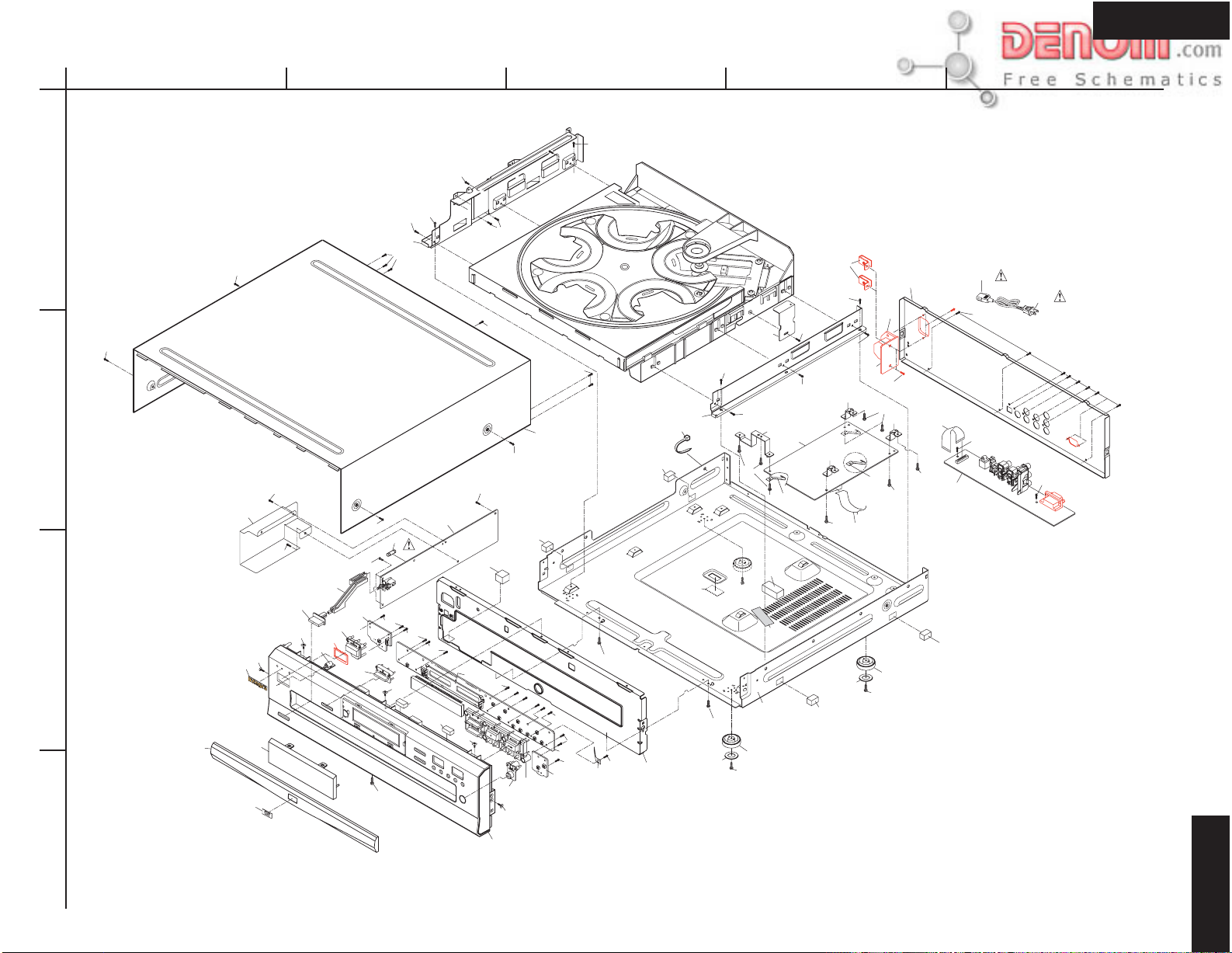
A
EXPLODEDVIEW
CHASSIS
1
S6
2
3
4
H2
S6
H44
H4
H1
H3
S5
S2
S2
H7
S4
H5
H8
H53
H6
BCDE
S1
S2
S1
U2
H10
S2
S6
S2
S2
H45
S3
F1
S4
S2
S2
H47
S2
F
L
tu
H47
H43
b
e
S4
H12
S2
H21
S3
S2
S2
H13
S6
H14
S5
H47
H15
H41
U2
S2
U2
S2
S2
S3
H27
S2
S2
H47
H20
H52
H46
H49
S2
H42
S1
S2
S2
S2
H22
H38
H48
H24
H23
H53
H27
U1
S2
S2
H26
H47
H52
S1
S2
H42
S2
H26
U2
H27
CC201
S2
H50
S2
H22
S2
H26
S2
H37
CC202
S2
U3
H47
H35
H34
S3
S2
1
CN0
S2
DPC-5.2
www.denom.com
Page 5
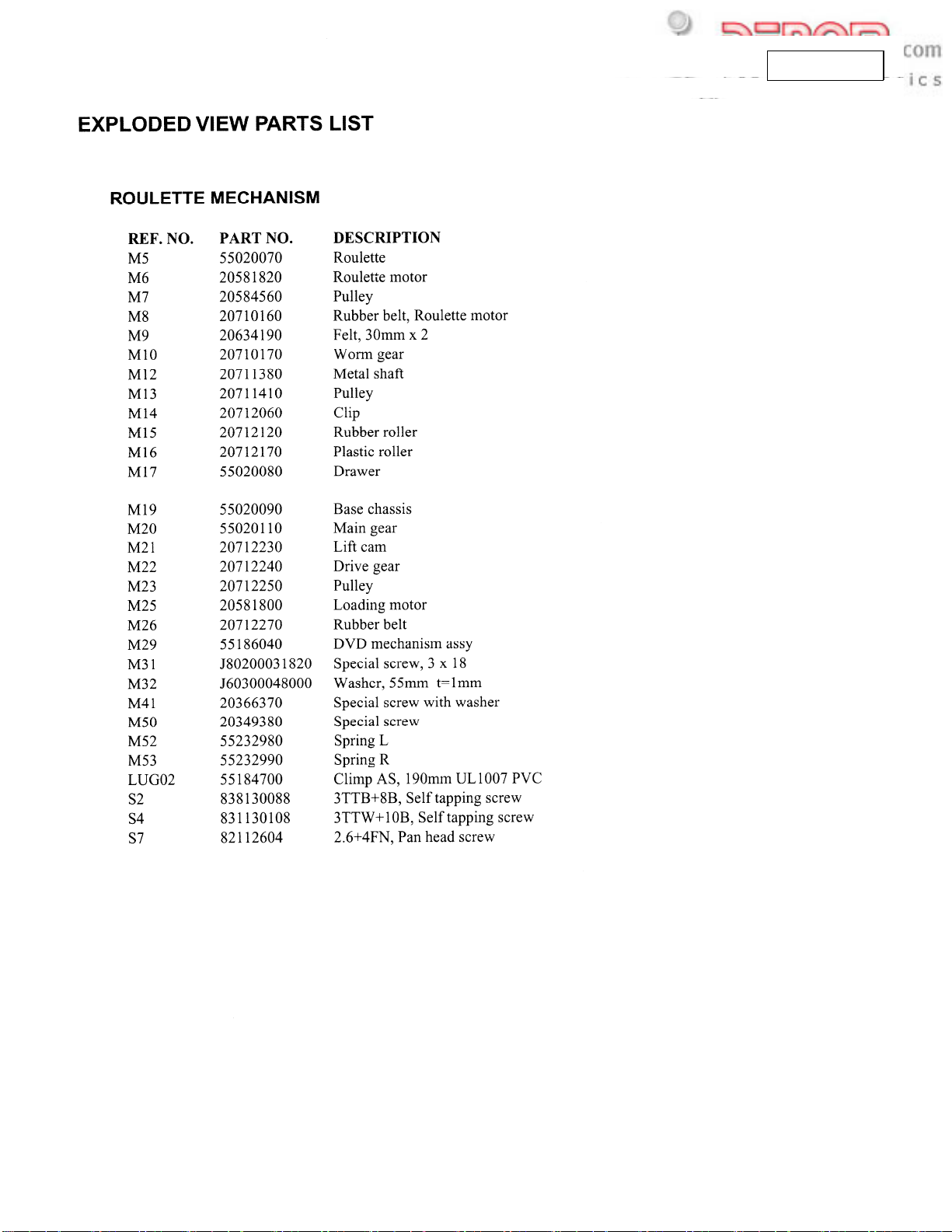
EXPLODED VIEW PARTS LIST
EXPLODED VIEW P ARTS LIST
DPC-5.2
NO PARTS No DESCRIPTION
H1 55221510 Badge, DVD
H2 55184480 Drawer panel
H3 55223420 Clear plate
H4 55204210 Logo badge, INTEGRA
H5 55186710 Holder
H6 55204250 Standby button
H7 55244620 Power button
H8 55184600 Shaft
H10 55244670 Button CD PLAY
H12 55164930 FL Holder
H13 55204180 Font panel
H14 55204260 Button OPEN/CLOSE
H15 55244680 Button, 9 Keys
H20 55236110 Front chassis
H21 55201610 Rubber spacer 14.5 x 14.5 x 22
H22 55125120 Leg
H23 55196510 Sponge, chassis 15 x 16 x 30
H24 55174580 Bracket ground
H26 55186640 Bracket, main board
H27 55178960 Spring, finger
H35 55222240 Power cord
H37 55204300 Rear panel
NO PARTS No
H38 55174610 Bracket R small
H41 55186600 Top cover
H43 55184690 Power supply board unit
H44 55202510 Shield cover
H45 55186670 Bracket L frame
H46 55186680 Bracket R frame
H46 55174680 Bracket roulette R
H47 55174550 Cushion, 12 x 8 x 20
H48 55186620 Main chassis
H49 55190690 Rubber sheet, down load
H50 55222010 AC Inlet terminal
H52 55222020 Bracket, AC inlet
H53 55259110 Cover, Standby button
U1 55203110 Main circuit PC board assy
U2 55203100 Display PC board assy ( Included Standby
U3 55203120 Output terminal PC board assy
U4 55186040 Mechanism PC board assy (Included sensor
DESCRIPTION
LED PCB +Connection PCB + Open/ Close
switch PCB +Inlet terminal PCB)
PCB +roulette motor PCB)
NOTE: THE COMPONENTS IDENTIFIED BY MARK
ARE CRITICAL FOR RISK OF FIRE AND
ELECTRIC SHOCK. REPLACE ONLY WITH
PART NUMBER SPECIFIED.
www.denom.com
Page 6

DPC 5.2
M18
20710180 GEAR
-
pp-6.max
www.denom.com
Page 7
DPC
-5.
2
M18
20710180
GEAR
pp-7.max
www.denom.com
Page 8
DPC-5.2
A
BLOCK DIAGRAM
1
2
AC120V 60Hz
BCDEFGH
CN701
RS-232 JACK
POWER SUPPLY
UNIT
3
+12V ANALOG VCC
+8V ANALOG VCC
-8V ANALOG VCC
+5V DIGITAL VCC
+3.3V DIGITAL VCC
+8V MOTOR VCC
+12V MOTOR VCC
5V DISPLAY
IC201
STI5519
MPEG
MUTE
S-VIDEO
L-CH MIXD
R-CH MIXD
CVBS-VIDEO
RCA 3V
JK804
4
TVM MECHA
F/E & MECHA
5
www.denom.com
Page 9
DPC-5.2
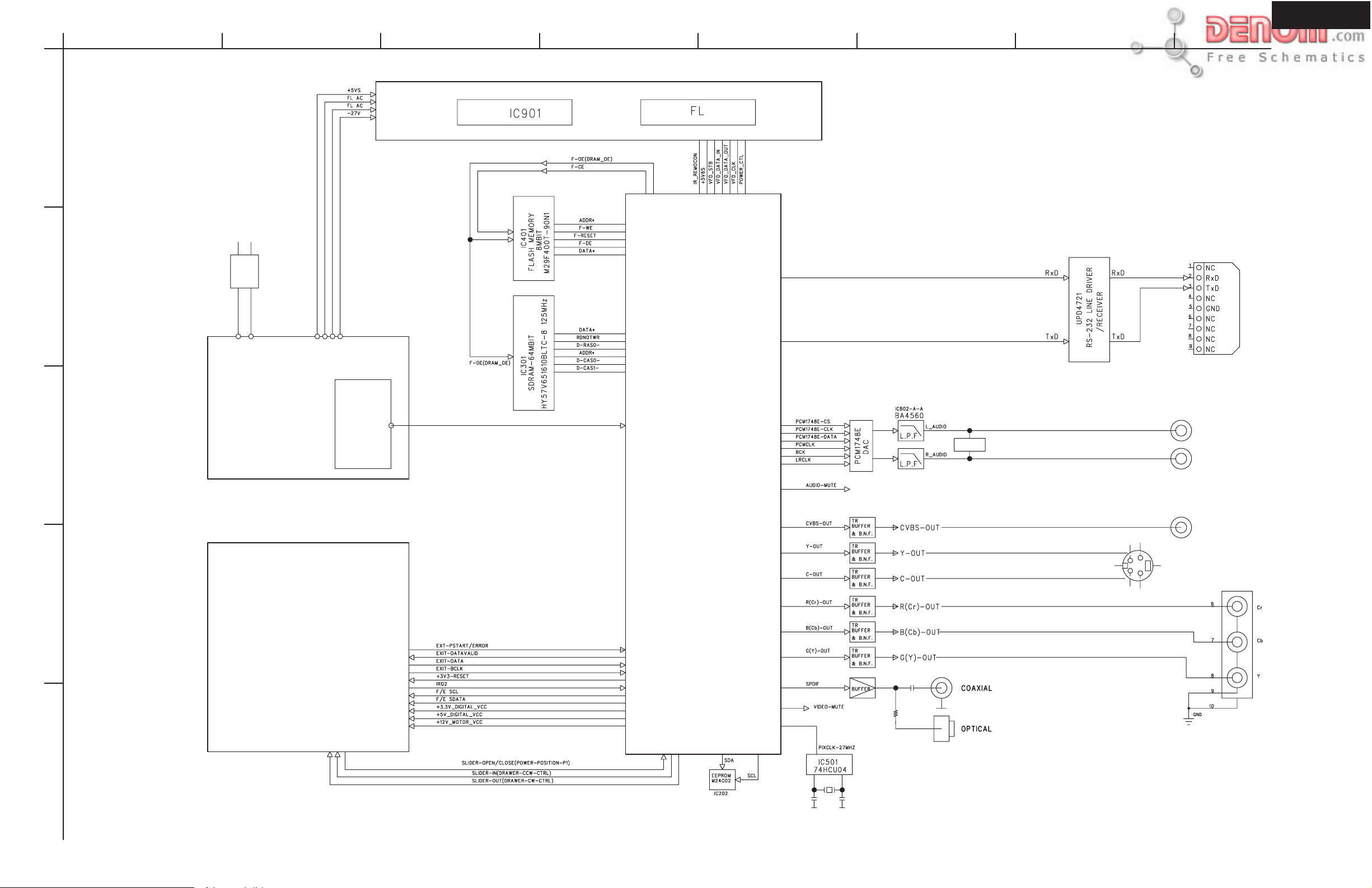
A
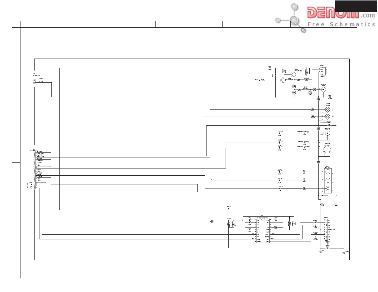
SCHEMATIC DIAGRAM
Output terminal PC board
1
From Main PC board
2
BCDE
OPTICAL
COAXIAL
Video output
From Main PC board
Component
3
RS-232C connector
4
www.denom.com
Page 10
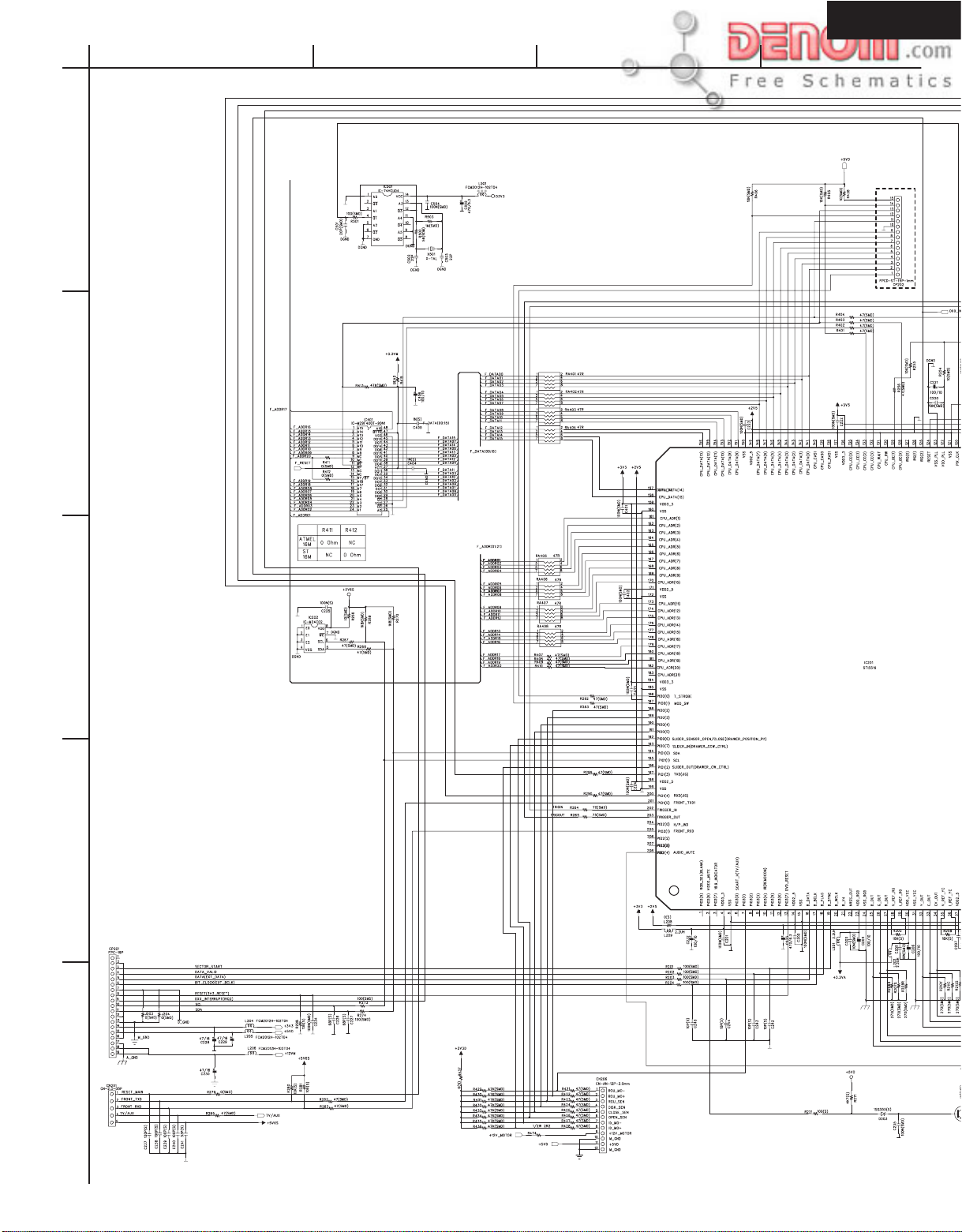
DPC-5.2
SCHEMATIC
DIAGRAM
1
2
A
Main circuit PC board
BCD
To Down load JIG
3
4
From Pick up
5
From Display PC board
To Mecha. control PC board
www.denom.com
Page 11

DPC-5.2
A
SCHEMATIC DIAGRAM
1
2
To Down load JIG
BCD
3
4
5
www.denom.com
Page 12

DPC-5.2
A
SCHEMATIC DIAGRAM
1
Connection board
2
BCDEFGH
From Power supply unit
Display circuit PC board
GRID(00:11)
Standby LED PC board
3
4
Open/Close
PC board
5
www.denom.com
Page 13

DPC-5.2
A
SCHEMATIC DIAGRAM
1
CN206
To Main control PC board
2
BCDE
Mechanism circuit PC board
3
To P003
PC board
4
To Mecha. control
Roulette motor PC board
www.denom.com
Page 14

DPC-5.2
A
PC BOARD CONNECTION DIAGRAM
AC 120V 60Hz
1
Power supply
2
circuit PC board
BCDE
Main circuit PC board
B08
DVD Mecha.
F/E PC board
Output terminal PC board
Connection
Power switch
PC board
3
Standby
switch
PC board
CP904
CN904
Display circuit PC board
Mechanism control PC board
MOTOR
OPEN/ CLOSE
switch PC board
DPC-5.2
4
www.denom.com
Page 15

PRINTED CIRCUIT BOARD PARTS LIST
Display PC board assy (PART NO. 55203100)
CIRCUIT NO. PART NO. DESCRIPTION CIRCUIT NO. PART NO. DESCRIPTION
ICs Capacitors
IC901 55183040NR CXP82324 C901 2034206030 47uF,+/-20%, 16V, Elect
IC902 55191090NR KIA7045 C903-C90 5, 202880 4091 0.1uF, +80-0%,Chip
Transistor C908,C911
Q901 5513318092 DTC114YKA C906 2025 205030 100uF,+/-20%, 6.3V, Elect
Remote sensor C907 2026862041 470uF,+/-20%, 6.3V, Elect
RM901 55156010NR NJL63H38 C909 2026884030 1uF,+/-20%, 50V, Elect
FL tube Switches
FL901 55183030NR HNA-12SM17 SW901,SW903, 55145270NR
Diodes SW905,SW907,
D904 7043654016 1N4148 SW911,SW913,
D905 55125510NR LED SW915,SW917,
D906 5517787088 RB501V-40 SW921,SW924,
Coils SW927,SW930,
L901 1403936091 22 u H , C h i p SW931
L902,L905 1 0 32875091 0 ohm, Chip Spring
L903,L904 2053866091 4.7 ohm, Chip FINGE 55178960 Finger type
L909,L912, 5512667050 Choke
L913,L914
Resonator
X901 55126140NR 10MHz
Socket AS
CN901 55191010NR
CN902 55182990NR
CN903 55199600NR
CN904, 55123320 2.0MM 5 MA ST
CN905
CN906 55199610NR
Socket
CP903 55090070
CP906 55123310
DPC-5.2
www.denom.com
Page 16

DPC-5.2
PRINTED CIRCUIT BOARD PARTS LIST
MAIN CIRCUIT PC BOARD ASSY (PART NO. 55203110)
CIRCUIT NO. PART NO. DESCRIPTION CIRCUIT NO. PART NO. DESCRIPTION
ICs Capacitors
IC201 55130350NR STI55, C201P,C204,C206, 2026894030 100uF, +/-20%,10V,
Video processor C210,C221,C232, Elect
IC202 20940740NR M24C02WM, C311,C406
EEPROM C220B,C220C, 2025267030 470uF, +/-20%,10V,
IC301 55156290NR HY57V65162, C220G,C220Y, Elect
DRAM C220R,C220S
IC302 55156030NR PCM1748 KE, C223B,C223C, 2025265030 220uF, +/-20%,16V,
D/A converter C223G,C223R, Elect
IC303 55128990NR BA4560F, C223S,C223Y
Ope. Amp. C228-C230, 2026783030 47uF, +/-20%,16V,
IC401 55177660NR SST39V, C301L,C301R, Elect
Flash memory C305L,C305R,
IC501 55133310NR M74HCU04M C306L,C306R,
IC21P 20361320NR 7806AP, Regulator C323
Transistors C233 2026862030 47uF, +/-20%,6.3V,
Q201-Q203 2097046092 KTC3875Y C325 Elect
Q220B,Q220C, 5513869056 KTN2907A C331 20269180AM 1uF, +/-20%,6.3V,
Q220G,Q220R, Elect
Q220S,Q220Y C327 1500213030 10uF, +/-20%,16V,
Q221B,Q221C, 5513871092 KTD1304 Elect
Q221G,Q221R, C505 2026862030 470uF, +/-20%,6.3V,
Q221S,Q221Y Elect
Q301 5513318092 DTC114YKA C302L,C302R 1013862091 2200pF, +/-10%,
Q301L,Q301R 5503943091 DTC323TK Chip
Q302L,Q302R 5513319092 DTA114YKA C221B,C221C, 1013867091 3300pF, +/-10%,
Coils C221G,C221R, Chip
L201-L203, 1404174091 C221S,C221Y
L209, C501 1037509091 20pF, +/-5%, Chip
L204-L206, 5512667050 Choke, 1uF C215,C217,C218, 2028804091 0.1uF, +80/-0%,
L210,R415, C222B,C222C, Chip
L501 C222G,C222R,
L208 1032875091 C222S,C222Y,
L211,L301 5512671050 C225,C234,C235,
L220B,L220C, 1404175091 Choke, 2.7uF C504
L220G,L220R, C502,C503 2050652091 22pF, +/-5%,
L220S,L220Y Chip
L302 1404174091 Choke, 2.2uF C321 2050654091 10pF, +/-0.5pF,
Resonator Chip
X501 55128980NR C237,C238, 2050659091 100pF, +/-5%,
C239,C240, Chip
C241,C307L,
C307R
www.denom.com
Page 17

PRINTED CIRCUIT BOARD PARTS LIST
t
t
t
t
t
t
OUTPUT TERMINAL PC BOARD ASSY (PART NO. 55203120)
CIRCUIT NO. PART NO. DESCRIPTION
ICs
IC701 55197900NR uPD4721, RS-232
IC805 55164740NR GP1F32T, Optical
Transistors
Q801 2097046092 KTC3875Y
Q802 2097048092 KTA1504Y
Coils
L801,L802, 5512662050 MT1, Choke
L803
Terminals
JK801 55164750XX Coaxial out
JK802 55175260XX RCA-2P out
JK803 55191220XX RCA-1P out
JK804 55149420XX Component ou
Socket
CN01 55124610XX 1.25mm 21P
Connector
CN701 67472300XX RS-232, 87204-606
Diode
D711 7043654016 1N4148
Capacitors
C701-C703, 2026884030 1uF, +20-80%, 50V, Elec
C706,C707
C705 2025205030 100uF, +20-80%, 6.3V, Elec
C802 2026783030 47uF, +20-80%, 16V, Elec
C820-C822, 2026862030 470uF, +20-80%, 6.3V, Elec
C825
C823,C824 2025265030 220uF, +20-80%, 16V, Elec
DPC-5.2
www.denom.com
Page 18

PARTS LIST
Mechanism control PC board assy (PART NO. 55183130)
CIRCUIT NO. PART NO. DESCRIPTION
ICs
IC001,IC002 20656300NR LB1641
Diodes
D001,D002 2041428001 1N5232B, 5.6V, Zener
Photo diodes
PI001-PI003 20586840NR ITR9606/F2
PI004 20556130NR GP2S28 20M
Coil
L001 20265120NR LF 39U0H +10% 130M
Capacitors
C001,C003 8043459071 22pF,+/-5%, Ceramic (CH)
C002,C004 20246950AF 0.1uF,+/-10%, Ceramic
C005 20268030AM 1000uF,+/-20%, 25V, Elect
Socket
P003 20504010XX 2.0MM 6 MA ST
P027 20713500NR 06187F
P406 55183020NR
Resistors
R001,R002 5088295016 100 ohm, +/-5%, 1/6W
R003,R004 2054943001 2.2 ohm, +/-5%, 1/2W
PC-5.2
www.denom.com
Page 19

DPC-5.2
PRINTED CIRCUIT BOARD PARTS LIST
MAIN CIRCUIT PC BOARD ASSY (PART NO. 55203110)
CIRCUIT NO. PART NO. DESCRIPTION CIRCUIT NO. PART NO. DESCRIPTION
Diodes C216 2050668091 470pF, +/-5%, Chip
D301 5517107050 UDZ 2.2 B, Zener C303L,C303R 2067807091 330pF, +/-5%, Chip
D303 2049651091 1SS355 C224B,C224C, 2099397091 390pF, +/-5%, Chip
Flat cables C224G,C224R,
CC201 55191150NR 19X 1.2 C224S,C224Y,
CC202 55182940NR 19X 1.2 C225B,C225C,
Socket AS C225G,C225R,
CN201 55182960NR C225S,C225Y
CN205 55182970NR C203,C205,C209, 1013896091 0.01uF +/-10%,Chip
CN207 55199620NR C220
Socket C211-C214, 2050654091 10pF +/-0.5pF, Chip
CN206 55123450 2.0MM 12 MA R C242-C245,
CP201 55124680 1.25MM 19 FE C328,C329
CP202 55125910NR 1.0MM 15 FE S C322,C324,C326 1013839091 560pF +/-10pF, Chip
CP203 55125910NR 1.0MM 15 FE S C404,C405 1013855091
CP205 55124600 1.25MM 19 FE Spring
55178960 Finger
1000pF +/-10%, Chip
www.denom.com
Page 20

P ANEL VIEW
DPC-5.2
FL DISPLAY
Inserted disc indicators
1
Indicate the type of current disc that is loaded.
Play/Pause indicators
2
Illuminate in play or pause mode.
Parental Lock indicator
3
Illuminates in parental lock mode.
4
TITLE indicator
Illuminates to indicate the current title number.
RESUME indicator
5
Illuminates when the player is ready for resume playback.
1
2 3 4
5
7
6
13 14 15
8
MEM. indicator
9
Illuminates during memory playback.
PBC indicator
10
Illuminates when PBC is on for Video CD.
INTRO indicator
11
Illuminates during intro-scan playback.
12
Elapsed time indicators
Indicate playing time.
Search indicators
13
Illuminate during search and slow playback mode.
9
10 11 12
6
CHPTER/TRACK indicators
Indicate display mode of the current chapter of DVD disc or
track number of Video CD or CD.
RANDOM indicator
7
Illuminates during random playback.
REPEAT indicators
8
Illuminate during repeat playback.
Disc number indicator/CD indicator
14
Disc number indicators indicate the presence of a disc. CD
indicator illuminates when the DVD Changer is in CD Play
mode.
15
Multifunction indicator
Indicates operating status, messages, etc.
www.denom.com
Page 21

DPC-5.2
A
PRINTED CIRCUIT BOARD VIEW
Main circuit board
1
2
BCDE
Top pattern and top parts
3
DPC-5.2
4
www.denom.com
Page 22

DPC-5.2
A
PRINTED CIRCUIT BOARD VIEW
Main circuit board
1
2
BCDE
Bottom pattern and bottom parts
3
DPC-5.2
4
www.denom.com
Page 23

DPC-5.2
A
PRINTED CIRCUIT BOARD VIEW
Output terminal PC board
1
CN701
2
BCDE
Component side view
3
Soldering side view
DPC-5.2
4
www.denom.com
Page 24

DPC-5.2
A
PRINTED CIRCUIT BOARD VIEW
1
Display circuit PC board
2
BCDE
Component side view
3
Soldering side view
4
www.denom.com
Page 25

DV-C503
A
PRINTED CIRCUIT BOARD VIEW
Mechanism control PC board
1
P004
2
BCDE
C003
C004
C002
R003
R004
JW10
D002
JW8
JW18
C001
IC001
D001
IC002
JW20
L001
C005
JW15
P406
JW6
JW13
JW17
JW21
R001
JW7
JW3
Component side view
P003
JW14
R002
JW22
Roulette motor PC board
3
Component side view
DV-C503
4
www.denom.com
Page 26

PRINTED CIRCUIT BOARD VIEW
Open/Close switch PC board
CP903
OPEN/CLOSE
SW930
Soldering side view
DPC-5.2
Standby switch PC board
Component side view
Connection PC board
1.RESET
2.RxD
3.TxD
4.TV/AUX
5.+5V6S
Component side view
Soldering side view
1.RESET
2.RxD
3.TxD
4.TV/AUX
To FRONT To MPEG
5.+5V6S
CN904
Inlet PC board
Component
www.denom.com
Page 27

DISASSEMBLY PROCEDURE
Replacement of DVD mechanism
The laser diode in the optical pickup block so
sensitive to static electricity, surge current and
etc..
That the components are liable to be broken down
or its reliability remarkable deteriorated.
During repair, carefully take the
following precautions.
Do not touch the optical
pickup object lens with the
hands.
Short Land
1. Remove the top cover with six screws.
2. Remove the tray.
3. Remove the roulette assembly.
4. Remove the roulette. (Roulette is removed as written below.)
5. Solder the LD output lands on the DVD optical pickup.
Please perform right photo to reference.
6. Replace the pickup mechanism assembly etc. . After unsolder the laser diodes
output lands.
DPC-5.2
Remove the roulette
1. Pull out the tray.
2. Stops in the position (cut deeply).
3. Remove in the direction of arrow.
4. Reassembly is performed by 3 to 1.
Roulette
Cut deep
www.denom.com
Page 28

P A CKING VIEW
DPC-5.2
12
8
24
RC-472DV
10
13
25
23
6
31
7
5
9
DPC-5.2
DPC-5.2
30
Front side
22
29
NOTE: THE COMPONENTS IDENTIFIED BY MARK
ARE CRITICAL FOR RISK OF FIRE AND
ELECTRIC SHOCK. REPLACE ONLY WITH
PART NUMBER SPECIFIED.
PARTS LIST
NO PARTS No DESCRIPTION
5 55204420 Carton box
6 55184410 Pad Right
7 55184420 Pad Left
8 55204310 Remote controller RC-472DV
9 55020220NR Battery, UM-4 x 2
10 55176530 Audio/ Video connection cable
12 55204320 Instruction manual
13 55186720 Warranty card
UPC Label
5ABC55DEFG
UPC
7 51398 00448 3
Serial No.
5ABC55DEFG
DV-C503
()
B
29363015
Continuation number: 4 Digit
Factory No.
Number of ten thousand digits
Month code : JAN=1, OCT=X
Year code
Line classification
BAR-CODE (UPC) and the figure
arefixed by model number
Serial No./ bar code (code 39)
NO PARTS No DESCRIPTION
22 55204330 UPC label
23 55170660 Sheet, Set, 1150 x 1000
24 55170650 Poly bag,335 x240mm
25 20715540 Poly bag, Power cord
29 55208740 Cushion, 35sq x 80
30 29110141 PP tape
31
55222240
Power cord
www.denom.com
Page 29

UPGRADE THE FIRMWARE 1
a. The program for writing
b. The program of binary form AAAABBB.bin AAAA : model name
Two files are saved to the same directory.
1. Jigs connection
1-1. PC-JIG
Connect the D-Sub(25 pin) cable.
1.2. JIG-DPC-5.2
Connect the FFC and socket (down load PCB).
1.3. Remove a sheet at the bottom.
Connect the socket (CP202).
1-4. Turn on the power switch of DPC-5.2.
Light up the LED on the JIG PC board assy.
1-5. Start an MS-DOS window.
(Click Strat, point to Programs, point to Accessories,
and then click MS-DOS Prompt.)
1-6. Input key the "dvd down AAAABBB.bin" and
then click Return.
BBB : Version
Down load JIG
Part number 0P42
DPC-5.2
Main PC board assy
(on the bottom side of DPC-5.2)
c5.2
To Computer
CP202
1 15
Connect the grade up jig
Part No. 0P42
www.denom.com
Page 30

UPGRADE THE FIRMWARE 2
1-7. Key input "Y".
It is automatically written in in order of Identify, ROM ERASE, WRITE and Verify.
Witting time are about 1 minute
c5.2
DPC-5.2
Writing was completed.
1-8. Press any key.
2. Confirmation of version of firmware
2-1. Press the "DIS 3" and "CDPLAY" key to the same timing.
The "DISC 3" key is pushed previously.
2-2. Version number is displayed on FL tube. (wait several seconds )
71AAA BBCC
Creation day
Creation month
Version number
ONKYO code
www.denom.com
Page 31

DPC-5.2
Integra Division of
ONKYO CORPORATION
Sales & Product Planning Div. : 2-1, Nisshin-cho, Neyagawa-shi, OSAKA 572-8540, JAPAN
Tel: 072-831-8111 Fax: 072-833-5222 http://www.onkyo.co.jp/
Integra Division of
ONKYO U.S.A. CORPORATION
18 Park Way, Upper Saddle River, N.J. 07458, U.S.A.
Tel: 201-785-2600 Fax: 201-785-2650 E-mail: integra@onkyousa.com http://www.integrahometheater.com
ONKYO EUROPE ELECTRONICS GmbH
Industriestrasse 20, 82110 Germering, GERMANY
Tel: 089-849-320 Fax: 089-849-3265 E-mail: info@onkyo.de
ONKYO CHINA LIMITED
Units 2102-2107, Metroplaza Tower I, 223 Hing Fong Road, Kwai Chung,
N.T., HONG KONG Tel: 852-2429-3118 Fax: 852-2428-9039
PN 0Mxxxx D01xx Printed in Japan
www.denom.com
 Loading...