

A - 65
ONKYO ® SERVICE MANUAL
SUPER SERVO INTEGRATED STEREO AMPLIFIER MODEL A-65

TABLE OF CONTENTS
| Item | Page |
|---|---|
| Specifications | 2 |
| Block diagram | 2 |
| Precautions | 4 |
| Circuit description | 4 |
| Component location | 6 |
| Exploded view | 7 |
| Parts list | 7 |
| Printed circuit board-parts list | 9 |
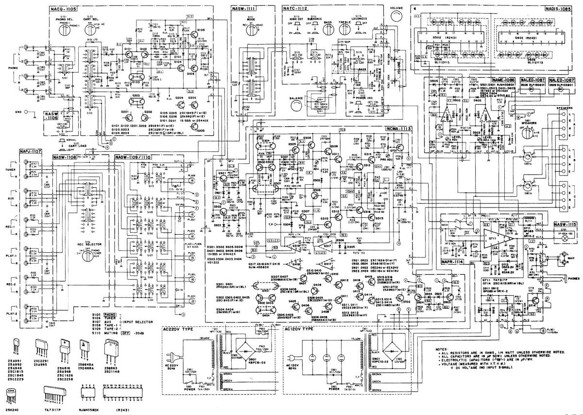
| Schematic diagram | 11 |
| Printed circuit board view from component side | 13 |
| Main amplifier adjustment | 18 |
| Packing procedures | 19 |

SPECIFICATIONS
| Power Output: | 100 watts per | channel min. RMS, | High Cut Filter: | 6 kHz (6 dB/oct.) |
|---|---|---|---|---|
| - | at 8 ohms bot | h channels driven. | Subsonic Filter: | 15 Hz (6 dB/oct.) |
| from 20 Hz to | 20 kHz. with no | Muting: | -20 dB | |
| more than 0.0 | 15%THD. | Loudness: | +7 dB at 70 Hz | |
| Total Hamonic Distortion: | 0.015% at rate | ed nower | +5 dB at 10 kHz | |
| IM Distortion | 0.015% at rate | ed nower | MAIN Output | 1.5V (600 ohms) |
| Damping Factor: | 50 at 8 ohms | in mit output. | ||
| Frequency Response | 2 50 000 H | z + 1 dB | Conoral | |
| RIAA Deviation (MM) | 2 - 30,000 11 |
Z + 1 0D
Jz + 0 2 dB |
Semiconductors: | & ICs 51 transistors 33 diades |
| Sensitivity and Impedance: |
20 - 20,000 I
Phone (MM): |
12 ± 0.2 uD
2 5mV/50kohms |
Semiconductors. | 26 LEDo |
| Sensitivity and impedance. | 2.5mV/30komms | Dimansional |
20 LEDS
419(W) × 151(H) × 402(D)mm |
|
| (MC). | 550μ V / 550011118 | Dimensions. | 16 1/20 5 15/160 15 12/160 | |
| Tuner: | XX7. 1 4 | 10-1/2 × 3-13/10 × 13-13/10 | ||
| Tape Play: | 150mV/SUKOnms | 15.5 kg, (34.2 lbs.) | ||
| Tape Rec: | 150mv/1konms | Power Supply: | AC 220 volts, 50 Hz, (G model) | |
| (phono) | AC 120 volts, 60 Hz (D model) | |||
| Phono Overload: | 250mV RMS : | at IkHz, 0.015% | ||
| THD. | Empoifications and facture | |||
| Bass Control: | ±8dB at 70 Hz | Z | Specifications and feature | es are subject to change without notice. |
| Treble Control: | ±8 dB at 10,00 | DO Hz | ||
| Signal to Noise Ratio: | Phono (MM): | 80dB (IHF A-202, | ||
| 5mV input, | ||||
| 1 watt output) | ||||
| (MC): | 68dB (IHF A-202, | |||
| 0.5mV input, | ||||
| 1 watt output) | ||||
| Tuner & Tape | :85dB (IHF A-202. | |||
| 0.5V input. | ||||
| 1 watt output) | ||||
| i wate output) |
BLOCK DIAGRAM

A-65
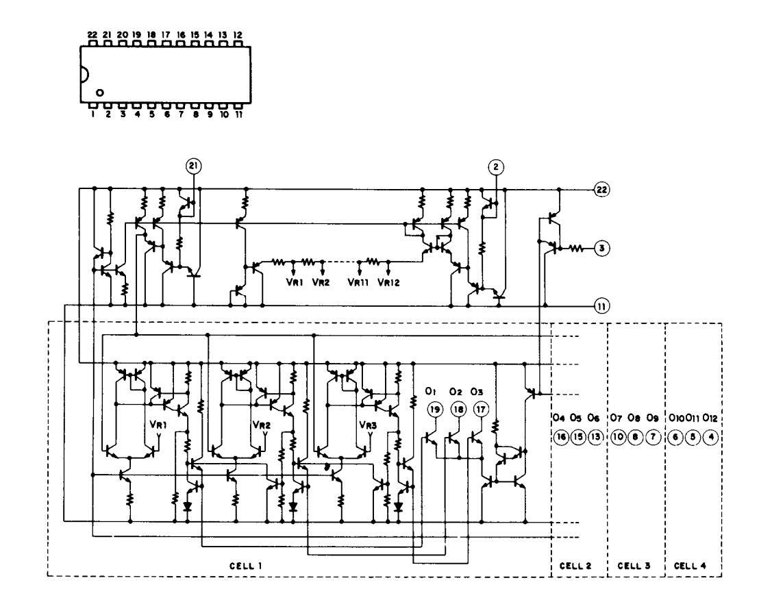
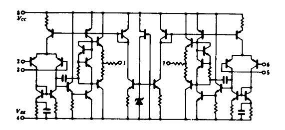
TA7317P (Protection Circuit)
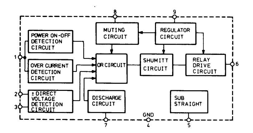
NJM4558 (Operation Amplifier)
PRECAUTIONS
1. For continued protection against risk of fire, replace only with same type and same rating fuse.
| CIRCUIT NO. | PARTS NO. | DESCRIPTION |
|---|---|---|
| F901 | 252052 | 7A (ST-6), AC fuse (120V model) |
| F901 | 252077 | 4A-SE-EAK, AC fuse (220V model) |
| F902, F903 | 252100 | 10A-EAK, AC fuse (220V model) |
2. Replacement for differential, driver, complementary and power amplifier transistors, if necessary, must be made from the same beta (hFE) group as the original type.
CIRCUIT DESCRIPTION
Dual Super-Servo
Onkyo's super-servo amp using ultralow frequency feedback servo circuits consisting of high-performance operational amplifiers has completely done away with a number of problems that have heretofore plagued amplifiers. These include distortion caused by capacitors used in the signal path, internally generated noise in the ultralow frequency range, and a lack of frequency response in the low ranges caused by record warp and tonearm resonance. Frequency response and tonal quality is as never before. The newly developed dual super-servo system has an additional function over our previous super-servo amp. That additional function may he noted by looking at the accompanying series of illustrations. First note the commonly used unbalanced NF amp depicted in Fig. 1 where the signal is input at point A as referenced to point B, and output at point C as referenced to point B. Common input/output reference in amplifiers is an ideal, but in fact difficult to attain This is narticularly true in power amps with high output current; unless impedances are matched, it is next to impossible. In Fig. 2, very small impedances are present at the same time return current is flowing from INPUT other circuits, thus the circuit in Fig. 2 may be considered equivalent to that of Fig. 3. Up to now, in order to lower these unnecessary impedances, large diameter wiring and busbar grounds have been used with some degree of effectiveness, however we have improved upon these methods. Looking at the problem from another angle, the dual super-servo solves the problem without improvisions. As noted in Fig. 4, by applying a superservo to the positive side, and with a servo return on the negative side, unnecessary signal components are equalized, consequently cancelled. And because the same potential exists, ground potential between input and output is the same. Put another way, in Fig. 5 and 6 the unnecessary components generated between input and output are short-circuited by the servo-circuit. Next. with separate amps, generally the preamp and main amp have been thought of as separate entities. A number of
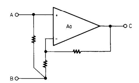


amp combinations have been used, but here again compatibility, or the lack of, may be attributed to ground potential in most cases. Also in the cables connecting 2 amps, there is cord impedance, contact resistence at the pin connector and wiring impedance to contend with, and even though the pin connectors are separated left from right, they became common via the power amp ground. This results in crosstalk between the left and right channel, poor channel separation, duller sound resolution and presence. And any difference in the ground potential between the preamp and power amp is detected and equalized by the servo. This is equal to the grounds of both amps being directly connected.
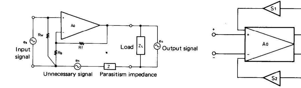

Fig. 4
Load
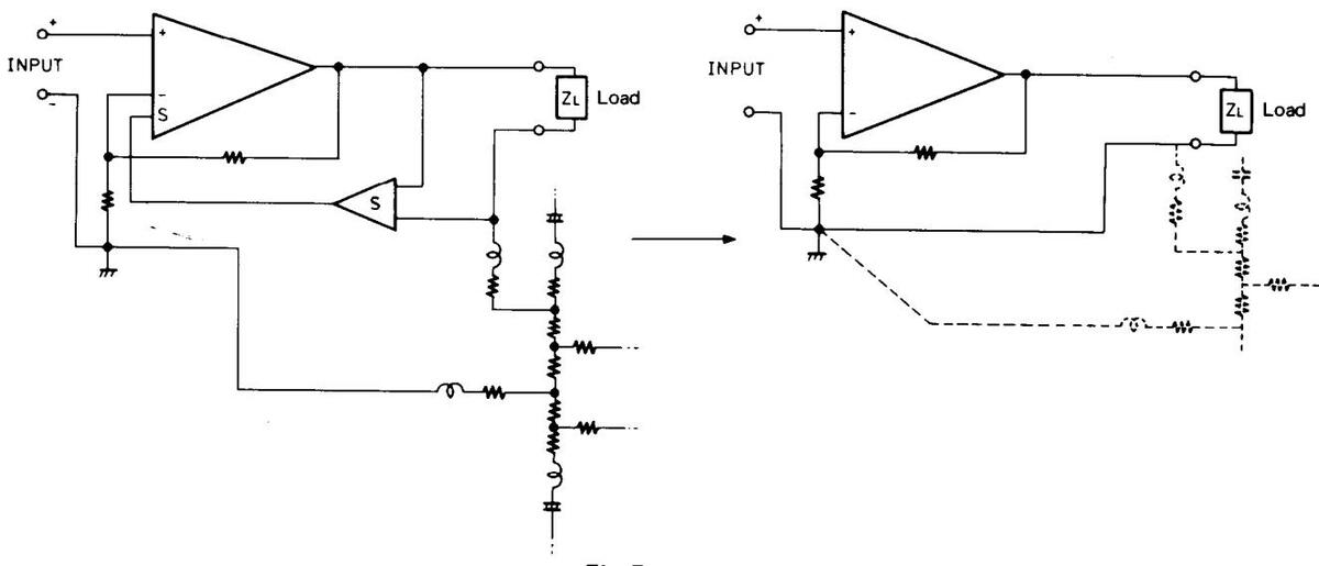
Fig. 5
Fig. 6
COMPONENT LOCATION
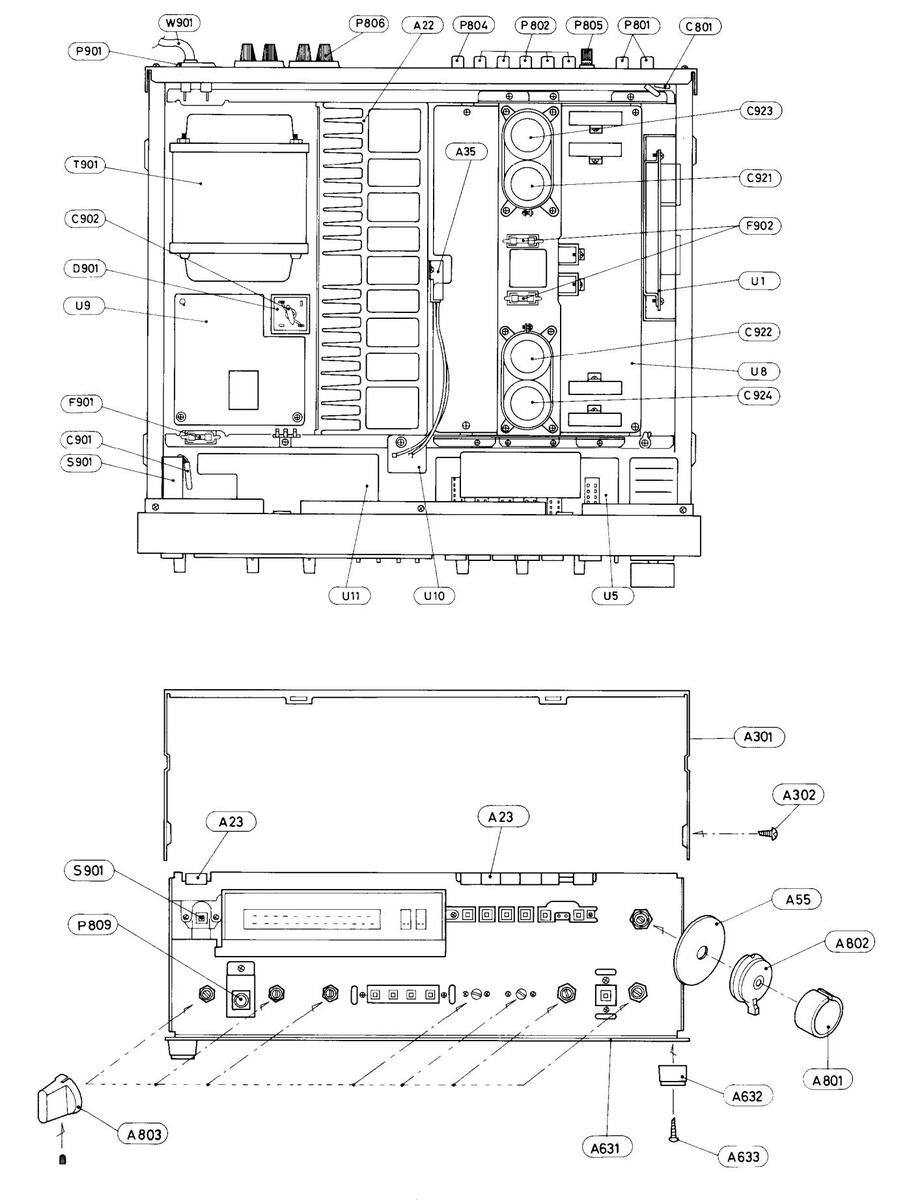
- 6 -
EXPLODED VIEW
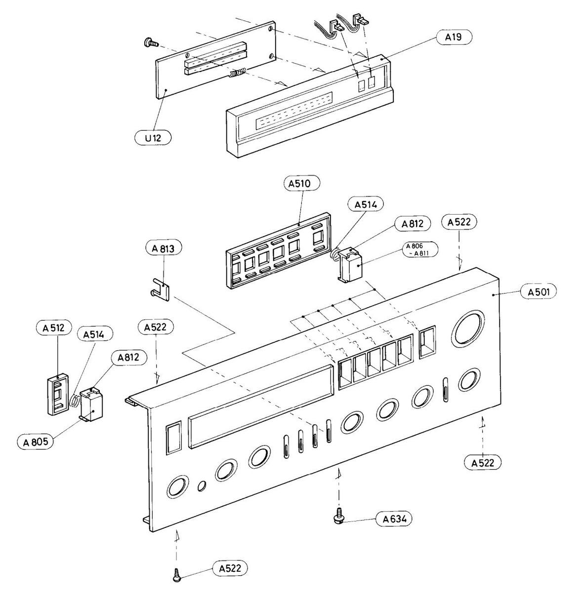
A-65
PARTS LIST
| SYMBOL NO. | PARTS NO. | DESCRIPTION | SYMBOL NO. | PARTS NO. | DESCRIPTION |
|---|---|---|---|---|---|
| A1 | 27110138 | Front bracket | A23 | 27300405 | Guide, lamp |
| A2 | 27130254 | Bracket, selector | A24 | 27190009 | LCB-4, Holder |
| A3 | 27140506 | Bracket, volume | A26 | 27120313 | Back panel (D) |
| A4 | 27140507 | Bracket, headphone | 27120314 | Back panel (G) | |
| A5 | 27150125 | Shielded plate | A34 | 223012 | Bracket |
| A6 | 27115026E | Side bracket | A35 | 270281 | Holder, thermal switch |
| A7 | 27130248 | Bracket, front | A37 | 834130068 | 3TTS+6B, Tap screw |
| A8 | 27130249 | Bracket, back | A39 | 834430068 | 3TTS+6B(BC), Tap screw |
| A9 | 27130250 | Bracket, power transformer | A40 | 834430108 | 3TTS+10B(BC), Tap screw |
| A11 | 27130251 | Bracket, equalizer | A41 | 834230108 | 3TTS+10B(Ni), Tap screw |
| A12 | 27130252A | Bracket | A42 | 838440109 | 4TTB+10BQ(BC), Tapping screw |
| A13 | 27150131 | Shielded plate, selector | A44 | 871140 | SW4, Washer |
| A14 | 27150132 | Shielded plate | A46 | 833140162 | 4STP+16BQ, Tapping screw |
| A15 | 27150130 | Shielded plate | A47 | 82113015 | 3P+15FN, Pan head screw |
| A16 | 27130253 | Band, capacitor | A48 | 82113006 | 3P+6FN, Pan head screw |
| A19 | 27190113 | Holder | A49 | 82113008 | 3P+8FN, Pan head screw |
| A20 | 28130116 | Plate | A50 | 831130088 | 3TTW+8B, Tap screw |
| A21 | 28199049 | Film | A51 | 834130108 | 3TTS+10B, Tap screw |
| A22 | 27160091A | Radiator | A52 | 834140108 | 4TTS+10B, Tap screw |
Q313, Q314 2201313 or Q413, Q414 2201312
| SYMBOL NO. | PARTS NO. | DESCRIPTION | SYMBOL NO. | PARTS NO. | DESCRIPTION |
|---|---|---|---|---|---|
| A55 | 28140126 | 53 q , Cushion | Q315, Q316 | 2201303 or | 2SB863(O) or |
| A56 | 28140050 | 0.8tx50x30mm, Cushion | Q415, Q416 | 2201302 | 2SB863(R), Power amplifier |
| A57 | 28140348 | 0.5tx54x3mm, Cushion | D171 D471 | transistor | |
| A58 | 28175037 | Insulating plate | R 171 , R 271 | 5104117 | N40DQL32C100KTP500KM35H, |
| A301 | 28184112 | Top cover | Volume/Balance control variable | ||
| A302 | 834430068 | 311S+6B(BC), 1ap screw | SIDIR | 25020104 | IESISTOR |
| A 303 | 28140020 | 4x10x40mm, Cushion | 3101D | 23030194 | NKSM-102-30BU, Phono selector |
| A501 | 12509121 | Front nanel ass'v | S103B | 25030193 | NRSM-103-30BU Cartridge |
| A502 | 28191085 | Clear plate | 51055 | 25050175 | selector switch |
| A503 | 27262096 | Plate, power | S801 | 25030196 | NRSM-226-30YW. Speaker |
| A504 | 27262097 | Plate A | selector switch | ||
| A505 | 27262098 | Plate B | S901 | 25035201 | NPS-111-L156P, Power switch |
| A506 | 27262099 | Plate C | (D) | ||
| A507 | 27262100 | Plate D | S901 | 25035051 | NPS-122-L16P, Power switch (G) |
| A508 | 27262101 | Plate E |
T901
T901 |
230499 | NPT-743D, Power transformer (D) |
| A509 | 27267113 | Guide, selector | 1901 | 230500 | NPT-743G, Power transformer |
|
A510
A511 |
27267114 | Guide power | I II | 12500505 |
(G)
NAEO 1105 Equalization emplifier |
| A512 | 27267116 |
Guide, power
Guide A |
01 | 12309303 | nAEQ-1105, Equalizer amplifier |
|
A512
A513 |
27267102 | Guide push | 112 | 12509506 | NASW-1106 Switch ne board |
| A514 | 28180079 | Spring | 02 | 12009000 | ass'v |
| A515 | 28199045 | Film | U3 | 12509507 | NAPJ-1107. Input/output |
| A518 | 27262105 | Plate F | terminal pc board ass'v | ||
| A522 | 834130068 | 3TTS+6B, Tap screw | U4 | 12509508 | NASW-1108, Recording selector |
| A631 | 27170104 | Bottom board | switch pc board ass'y | ||
| A632 | 27175009A | Leg | U5 | 12509509 | NASW-1109, Input selector pc |
| A633 | 831130128 | 3TTW+12B, Tap screw | board ass'y | ||
| A634 | 831130068 | 3TTW+6B, Tap screw | U6 | 12509511 | NASW-1111, Switch pc board |
| A801 | 28320553 | Knob, volume | 117 | 12500512 | ass'y |
| A802 | 28320554 | Knob, balance | 07 | 12509512 | NAIC-1112, Tone control pc |
| A803 | 20320329 | Knob, selector | 118 | 12500513 | NAMA 1112 Bower emplifier |
| 4805 | 28320546 | Knob power | 00 | 12507515 | nc hoard ass'y |
| A806 | 28320547 | Knob, tape 2 | U9 | 12509514 | NAPR-1114. Protector circuit |
| A807 | 28320548 | Knob, tape 1 | pc board ass'y | ||
| A808 | 28320549 | Knob, aux. | U10 | 12509515 | NASW-1115, Thermal detector |
| A809 | 28320550 | Knob, tuner | switch pc board ass'y | ||
| A810 | 28320551 | Knob, phono | U11 | 12509516B | NAME-1086b, Output power |
| A811 | 28320552 | Knob, muting | 1110 | 10540505 | indicator circuit pc board ass'y |
| A812 | 28320545 | Knob, base | 012 | 12549585 | NADIS-1085, Output power |
| A813 | 28320530 | Knob, push | 1113 1114 | 12540597 | indicator circuit pc board ass'y |
| C901 | 27300080 | Cover canacitor (D) | 015, 014 | 12549567 | LED no board ass'y |
| C901a | 3500058 | PMF265MB510 IS capacitor (G) | W901 | 2530994 | AS-UC-3 Power supply cable (D) |
| C902 | 335251039 | 0.01µF. 500V. Ceramic capacitor | W901 | 253092 | AS-CEE-2. Power supply cable (G) |
| C801-C804 | 379124737 | 0.047µF, 50V, DEW capacitor | W901a | 270025 | SR-3P-4, Strainrelief (D) |
| C809 | 335321025 | 1000pF, 50V, Ceramic capacitor | W901c | 270280 | SR-4K-4, Strainrelief (G) |
| (G) | |||||
| C921–C924 | 3504160 | 12,000µF, 63V, Elect. capacitor | Note: D: Only 1 | 20V model G: | Only 220 model |
| D901 | 223861 | KBC10-02, Silicon diode | |||
| F901 | 252077 | 4A-SE-EAK, AC fuse (G) | |||
| F901a | 25065096 | NPF-073, Fuse holder (G) | |||
| F902, F903 | 252100 | IUA-EAK, AC IUSE (G) | |||
|
F902a, F905a
DI 001 |
23063096 |
NPF-0/5, Fuse holder (G)
PL 14V0.06AW 2.5, Power |
|||
| 11,701 | 210121 | indicator lamp | |||
| P 801 | 25045044 | NPI-4PRBL21 Phono input | |||
| 20010011 | terminal | ||||
| P804 | 25045026 | NPJ-2PRBL04, Main output | |||
| terminal | |||||
| P805 | 25060044 | Ground terminal | |||
| P805a | 87613010 | W3×10F, Washer | |||
| F805b | 87313006 | M3-B, Toothed washer | |||
| P806-P808 | 25060029 | NTM-4PRMN05, Speaker | |||
| Deaa | 25045062 | terminal | |||
| r003 | 23043067 | nLJ-U2/9-U1-U/U, Stereo | |||
| P901_P903 | 25050046 4 | NSCT-2P15 Ac outlet (D) | |||
| O308. O408 | 2211255 or | 2SC1815(GR) or | |||
| 2000, 2100 | 2211256 | 2SC1815(BL), Thermal detector | |||
|
|
transistor |
transistor 2SD1148(O) or 2SD1148(R), Power transistor
EQUALIZER AMPLIFIER PC BOARD (NAEQ-1105) – PARTS LIST
| CIRCUIT NO. | PARTS NO. | DESCRIPTION | CIRCUIT NO. | PA |
|---|---|---|---|---|
| Transistors | Ca | |||
| 0101.01027 | 2211783 or | 2SA991(E) or | C156, C256 | 379 |
| 0201 0202 | 2211782 | 2SA991(F) | C157, C257 | 379 |
| 0103 0203 | 2211445 or | 2SC2291(F) or | C171 C271 | 379 |
| Q105, Q205 | 2211445 01 | 25C2291(1) 01 | C173 C273 | 370 |
| 0104 0204 | 2211440 | 25C1215L(CD) == | C173, C273 | 270 |
| Q104, Q204 | 2211895 of | 25C1815L(GR) of | 0174, 0274 | 272 |
| 2211896 | 2SC1815L(BL) | C175, C275 | 31 | |
| Q105, Q205 | 2211732 or | 2SC1845(F) or | Re | |
| 2211733 | 2SC1845(E) | R161 R261 | 13 | |
| 0106. 0206 | 2211792 or | 2SA992(F) or | R101, R201 |
-
|
| • | 2211793 | 2SA992(E) | R172, R272 | 21, |
| 2211/20 | -2 | R1/6, R2/6 | 4.0 | |
| Diodes | R1/4, R1/8 | 43 | ||
| D101, D201 | 223133 or | DS442X or | R182, R274 | |
| 223105 | 1$1555 | R278, R282 | ||
| R180, R280 | 514 | |||
| Capacitors | , | |||
| C102, C202 | 391041007 | 10µF, 16V, LL | ||
| C107, C207 | 352724719 | 470μF,6.3V, Elect. | Sw | |
| C110, C210 | 352761019 | 100μF, 35V, Elect. | S112-S115 | 250 |
| C111. C211 | 379122235 | 0.022µF±10%, 50V, DEW | ||
| C112 C212 | 352980226 | 2.2µF 50V Non-nolar elect | ||
| C112, C212 | 379121225 | 1 200pE+10% 50V DEW | POWER AN | ИРІ |
| C115, C215 | 270121225 | 0.019E+5% 50V DEW | (NIAMA 111 | 2) |
| 0116 0216 | 270121624 | 1.500Ε.50 50V DEW | 5) | |
| C116, C216 | 3/9121524 | 1,500pF±5%, 50V, DEW | CIDCUIT NO | D٨ |
| CI17, C217 | 379125624 | 5,600pF±5%, 50V, DEW | circon no. | IA |
| C118, C218 | 379121024 | 1,000pF±5%, 50V, DEW | ICs | |
| C121, C122 | 352761019 | 100µF, 35V, Elect. | 0317.0318 | 222 |
| Desistant | 0417 0418 | |||
| D110 D1207 | AAAGAAAAA | 120 1/0W Matel and a film | ||
| R119, R120 | 442521204 | 1252, 1/2w, Metal oxide film | Tra | |
| R219, R220 _ | Q301, Q401 | 22 | ||
| R126, R226 | 442621234 | 12kΩ, 1W, Metal oxide film | 22 | |
| Switches | O302. O303 ] | 22 | ||
| C101A | 25065150 | NES 2272 Dhone 1/2 colortor | 0402 0403 | 22 |
| 5101A | 25065159 | NSO-2272, Filono 172 selector | 0304 0404 | 22 |
| $103A | 25065156 | NSS-83/1, Cantridge selector | QJ07, QT07 | 22 |
| 0105 0405 | 22 | |||
| OWITCH D | Q305, Q405 | 22. | ||
| SWITCH P | C BOARDS | 22. | ||
| (NASW-110 | 6/1108/1109 | )/1111/1115) – PARTS LIST | Q306, Q406 | 22 |
| (1.1.1.2.1.1.1.0 | 0,1100,110 | ,,, | 22 | |
| CIRCUIT NO. | PARTS NO. | DESCRIPTION | Q307, Q407 | 22 |
| 22 | ||||
| Capacitor | O308, O408 | 22 | ||
| C151 | 352741009 | 10µF, 16V, Elect. | - / - | 22 |
| Lamos | 0309 0409 | 22 | ||
| 210122 | DI 14VO OGAWO G Input | Q309, Q409 | 22 | |
| rL001-rL000 | 210125 | FL14 V0.00A w-0.0, Input | 0210 0410 | 22 |
| indicator | Q310, Q410 | 22 | ||
| Switches | 22. | |||
| $102 | 25035257 | NPS-122-L221 Cartridge load | Q311, Q411 | 220 |
| 5102 | 230,33237 | alastar | 220 | |
| 0104 | 25020105 | 0312, 0412 | 220 | |
| $104 | 25030195 | NKSM-146-30SS, Recording | 220 | |
| selector | 0313 03147 | 220 | ||
| S105-S109 | 25035255 | NPS-562-L219, Input selector | 0413 0414 | 221 |
| S110 | 25035164 | NPS-142-L128, Muting | Q413, Q414 ] | 221 |
| $111 | 25030190 | NRSM-145-30SS, Mode | Q315, Q316 | 220 |
| S701 | 25065127 | 1P-105A-100. Thermal detector | Q415, Q416 | 220 |
| ~/ • • | 1. 10011 100, 1.001mai avivetoi | Q701, Q702 | 22 | |
| 22 | ||||
| ГРИТ ТЕРМ | INAL PC BOAPD | Q921, Q923 | 220 | |
| 220 | ||||
| (INAPJ-1107 | ') — PARTS I | L131 | 0922, 0924 | 2.21 |
(NAPJ-1107) – PARTS LIST
| CIRCUIT NO. | PARTS NO. | DESCRIPTION |
|---|---|---|
| C805-C808 |
Capacitors
379124737 |
0.047µF±20%, 50V, DEW |
| P8 02, P 803 |
Terminals
25045072 |
NPJ-6PDBL36, Input/output |
TONE CONTROL PC BOARD (NATC-1112) – PARTS LIST
| CIRCUIT NO. | PARTS NO. | DESCRIPTION |
|---|---|---|
| Capacitors | ||
| C156, C256 | 379122245 | 0.22μF±10%, 50V, DEW |
| C157, C257 | 379124725 | 4,700pF±10%, 50V, DEW |
| C171, C271 | 379121235 | 0.012µF±10%, 50V, DEW |
| C173, C273 | 379123935 | 0.039µF±10%, 50V, DEW |
| C174, C274 | 379121025 | 1,000pF±10%, 50V, DEW |
| C175, C275 | 379126825 | 6,800pF±10%, 50V, DEW |
| Resistors | ||
| R161, R261 | 431421567 | 15MΩ, 1/4W, Solid |
| R172, R272 | 5148071 | N16RQM11C110K180K30M, |
| R176, R276 | Bass control variable | |
| R174, R178 | 431421567 | 15MΩ, 1/4W, Solid |
| R182, R274 | ||
| R278, R282 | ||
| R180, R280 | 5148072 | N16RGM11C220K30M, Treble |
| control variable | ||
| S112-S115 |
Switches
25035256 |
NPS-422-L220, Loudness/Hi-cut/
Subsonic |
| POWER AN | ADI IFIFR P | C BOARD |
| (NAMA-111 | 3) – PARTS | LIST |
| CIRCUIT NO. | PARTS NO. | DESCRIPTION |
| ICs | ||
| 0317.0318 | 222502 | NIM-4558DX |
| 0417. 0418 | 222002 | |
| 0201 0401 | 25V240(CD) | |
| Q301, Q401 | 2211915 or | 25K240(GR) of |
| 0.00 0.007 | 2211910 | 25K240(BL) |
| Q302, Q303 | 2211/32 OF | 25C1845(F) OF |
| Q402, Q403 | 2211/33 | 25C1845(E) |
| Q304, Q404 | 2211515 OF |
25A995(F) 01
25A005(F) |
| 0205 0405 | 2211310 |
25A995(E)
25A002(E) or |
| Q303, Q403 | 2211792 01 | 25A992(F) |
| 0306 0406 |
2211795
2211593 or |
25R552(E)
25R6484(C) or |
| Q300, Q4 00 | 2211595 01 |
250040A(C) 01
258648A(B) |
| 0307 0407 |
2211572
2211603 or |
2SD668A(C) or |
| 2507, 2407 | 2211602 | 2SD668A(B) |
| O308, O408 | 2211255 or | 2SC1815(GR) or |
| 2000, 2.00 | 2211256 | 2SC1815(BL) |
| 0309. 0409 | 2211634 or | 2SC2229(Y) or |
| 2003, 2003 | 2211633 | 2SC2229(0) |
| O310, O410 | 2211354 or | 2SA949(Y) or |
| 2211353 | 2SA949(O) | |
| Q311, Q411 | 2200864 or | 2SC2238(Y) or |
| 2200863 | 2SC2238(O) | |
| Q312, Q412 | 2200874 or | 2SA968(Y) or |
| 2200873 | 2SA968(O) | |
| Q313, Q314 ] | 2201313 or | 2SD1148(O) or |
| Q413, Q414 | 2201312 | 2SD1148(R) |
| Q315, Q316 | 2201302 | 2SB863(R) |
| Q415, Q416 🗍 | 2201303 or | 2SB863(O) or |
| Q701, Q702 | 2211792 or | 2SA992(F) or |
| 2211793 | 2SA992(E) | |
| Q921, Q923 | 2200664 or | 2SC1626(Y) or |
| 2200663 | 2SC1626(O) | |
| Q922, Q924 | 2200674 or | 2SA816(Y) or |
| 2200673 | 2SA816(O) | |
| Diodes | ||
| D301, D302 | 223105 ог | 1S1555 or |
| D305, D306 | 223133 | DS442X |
| D401, D402 | ||
| D405, D406 | ||
| D303, D403 | 4000068 | VD1222 |
| D304, D404 |
| CIRCUIT NO | ΒΑ ΒΤ Ω ΝΟ | DESCRIPTION |
|---|---|---|
| CIRCUIT NO. | FARISINO. | DESCRIPTION |
| D921, D922 | 224071 or | 05Z24U or |
| 022 0024 | 224126 | GZA24U |
| D923, D924 | 224003 01 | |
| 224120 | OZA180 | |
| Coils | ||
| L301, L401 | 231015 | S-0.8C |
| Capacitors | ||
| C303, C403 | 379121035 | 0.01µF±10%, 50V, DEW |
| C309, C409 | 379121025 | 1,000pF±10%, 50V, DEW |
| C311, C411 | 379121035 | 0.01µF±10%, 50V, DEW |
| C323, C423 | 379134735 | 0.047µF±10%, 50V, DEW |
| C331, C332 | 352752209 | 22µF, 25V, Elect. |
| C431, C432 | ||
| C925, C926 | 352784709 | 47μF, 50V, Elect. |
| C927, C928 | 352761019 | 100µF, 35V, Elect. |
| C929, C930 | 352760479 | 4.7μF, 35V, Elect. |
| C931–C934 | 352754709 | 47μF, 25V, Elect. |
| Resistors | ||
| R309, R409 | 442623614 | 360Ω, 1W, Metal oxide film |
| R315, R415 | 5225072 | N10HR4.7KBDM, Idling current |
| adjustment | ||
| R331, R431 | 442524714 | 470Ω, 1/2W, Metal oxide film |
| R332, R432 | ||
| R333, R433 | 442621524 | 150Ω, 1W, Metal oxide film |
| R334-R337 | 442520224 | 2.2Ω, 1/2W, Metal oxide film |
| R434-R437 | 40000 60 | |
| R338-R341 | 4000060 | 0.27Ω, 2W, Metal plate |
| R438-R441 | 440700104 | |
| R342, R343 | 442/20104 | 10, 2W, Metal oxide film |
| K442, K443 | 4000000 | 0.470 SW Metal state |
|
K 344 - K 34 /
D 1 |
4000080 | 0.4752, 5w, Metal plate |
| R444-R447 | 117670561 | 5.60 1W Matel oxide film |
| R350, R450 | 442020304 | 100 1W Metal oxide film |
| R352 R452 | 442626834 | 68k0 1W Metal oxide film |
| R705 R706 | 5225005 | N10HR2 2KRD Current detector |
| 5225005 | level adjustment | |
| R921, R922 | 442524714 | 470Ω, 1/2W, Metal oxide film |
| R923, R924 | 442523924 | 3.9kΩ, 1/2W, Metal oxide film |
| R927, R928 | 442525614 | 560Ω, 1/2W, Metal oxide film |
PROTECTOR CIRCUIT PC BOARD (NAPR-1114) – PARTS LIST
| CIRCUIT NO. | PARTS NO. | DESCRIPTION |
|---|---|---|
| 0711 |
IC
2225.84 |
T & 7217D |
| Q/II | 222304 | IA/JI/F |
| Transistor | ||
| Q714 | 2211255 or | 2SC1815(GR) or |
| 2211256 | 2SC1815(BL) | |
| Diodes | ||
| D711, D712 | 223848 or | GP-08B or |
| D911, D912 | 223804 | SR1K-2 |
| D713 | 224043 or | 05Z6.2U or |
| 224098 | GZA6.2U | |
| Capacitors | ||
| C711, C712 | 352922206 | 22µF, 6.3V, Non-polar |
| C714 | 352732209 | 22µF, 10V, Elect. |
| C715 | 352784799 | 0.47µF, 50V, Elect. |
| C716 | 352743319 | 330μF, 16V, Elect. |
| C912, C915 | 352741029 | 1,000µF, 16V, Elect. |
| C914 | 352744719 | 470μF, 16V, Elect. |
| Resistors | ||
| R751, R752 | 441723904 | 390Ω, 2W, Metal oxide film |
| R911 | 442521004 | 10Ω, 1/2W, Metal oxide film |
| R912 | 442522204 | 22Ω, 1/2W, Metal oxide film |
| Relay | ||
| RL711 | 25065036 | NRL-4P3A-DC12-01, Speaker |
OUTPUT POWER INDICATOR PC BOARD (NADIS-1085) – PARTS LIST
| CIRCUIT NO. | PARTS NO. | DESCRIPTION |
|---|---|---|
| Q502, Q602 | 222621 | IR2431, IC |
| D506, D606 | 225068 | GL-112V13, L.E.D |
OUTPUT POWER INDICATOR DRIVER PC BOARD (NAME-1086b) – PARTS LIST
| CIRCUIT NO. | PARTS NO., | DESCRIPTION |
|---|---|---|
| Q501–Q601 |
IC
222502 or 222597 |
NJM-4558DX or
NJM-4558DN |
|
D501–D503
D504, D505 D601–D603 |
Diodes
223133 or 223105 224096 or 224041 223133 or 223105 |
DS442X or
1S1555 GZA5.6-U or 05Z5.6-U DS442X or 1S1555 |
|
C502, C602
C503 C504, C505 C506 C508 |
Capacitors
352780229 352734709 352754709 352780339 352780479 |
|
|
R502, R602
R515 |
Resistors
5215021 442521014 |
N08HR10KBD, Semi-fixed
100Ω, 1/2W, Metal oxide film |
CARTRIDGE SELECTOR INDICATOR PC BOARD (NALED-1087) – PARTS LIST
| CIRCUIT NO. | PARTS NO. | DESCRIPTION |
|---|---|---|
| D508, D509 | 225082 | SLP-155B-01, L.E.D. |
ONKYO CORPORATION
MAIN AMPLIFIER ADJUSTMENT
Set the all control knobs to standard position.
| Standard knob position | |
|---|---|
| SELECTOR | AUX |
| VOLUME | Minimum |
| BALANCE | CENTER |
| MODE | STEREO |
| LOUDNESS, SUBSONIC FIL., HI-CUT FIL. | OFF |
| BASS/TREBLE | OFF |
| SPEAKERS | Α |
| MUTING | OFF |
1. IDLING CURRENT ADJUSTMENT
1. Connect the DC voltmeter between IID and VCT terminals.
2. Adjust the voltage to 12±3mV with semi-fixed resistor of R315 and R415.
NOTES: Adjust after switching on for 5 minutes.
| VOLUME |
Minimum |
|---|---|
| LOAD |
Open |
2. CURRENT DETECTOR LEVEL ADJUSTMENT

3. OUTPUT INDICATOR LEVEL ADJUSTMENT
- 1. Connect the AF oscillator across AUX terminal and AC voltmeter across speaker terminals.
- 2. Connect the hollow resistor of 8 ohms across speaker terminal (A).
- 3. Set the AF oscillator output to 100mV, 1kHz.
- 4. Adjust the output voltage to 21.1V with volume control.
- 5. Then adjust the semi-fixed resistor of R502 and R602 so that the 11th L.E.D. lights up.
PACKING PROCEDURES

PACKING PROCEDURES – PARTS LIST
| SYMBOL NO. | PARTS NO. | DESCRIPTION |
|---|---|---|
| A851 | 29050454 | Master carton box |
| A852 | 29090401A | Pad, bottom |
| A853 | 29090399 | Pad, upper |
| A854 | 29090399-1 | Pad, upper, right |
| A857 | 29095115 | 500×1, 100mm, Protection sheet |
| A858 | 29100034 | 850×650mm, Poly bag |
| A859 | 282301 | Sealing hook |
| A861 | 260012 | Damplon tape |
| A881 | Accessary bag ass'y | |
| 29340507 | Instruction manual (D) | |
| 29340508 | Instruction manual (G) | |
| 29365006 | Warranty card (N) | |
| 29365005-3 | Warranty card (V) | |
| 29358002 | Service station list (N) | |
| 29100006 | 250×350mm, Poly bag | |
| Note: |
(D)
(G) (V) (N) |
Only 120V model
Only 220V model Only West Germany model Only U.S.A. model |
|---|


 Loading...