

Omron ZUV, ZUV-C30H User Manual
Smart Curing System
Mega Power Type
ZUV Series
User's Manual
Cat. No. Z281-E1-02

Introduction
Thank you for purchasing the ZUV.
This manual provides information regarding functions, performance and operating methods that
are required for using the ZUV.
When using the ZUV, be sure to observe the following:
• The ZUV must be operated by personnel knowledgeable in electrical engineering.
• To ensure correct use, please read this manual thoroughly to deepen your understanding of the
product.
• Please keep this manual in a safe place so that it can be referred to whenever necessary.

Introduction
Section 1
Section 2
Section 3
Section 4
Section 5
Terms and Conditions Agreement
OVERVIEW & INSTALLATION AND CONNECTION
ZUV BASIC OPERATION
SETUP
CONNECTING TO EXTERNAL DEVICES
APPENDIX
Introduction
Section 1 Section 2 Section 3 Section 4 Section 5
User's Manual
Smart Curing System
Mega Power Type
ZUV Series

Introduction
Introduction
Terms and Conditions Agreement
Warranty, Limitations of Liability
■ Warranties
●
Exclusive Warranty
Omron’s exclusive warranty is that the Products will be free from defects in materials
and workmanship for a period of twelve months from the date of sale by Omron (or
such other period expressed in writing by Omron). Omron disclaims all other
warranties, express or implied.
● Limitations
OMRON MAKES NO WARRANTY OR REPRESENTATION, EXPRESS OR IMPLIED,
ABOUT NON-INFRINGEMENT, MERCHANTABILITY OR FITNESS FOR A
PARTICULAR PURPOSE OF THE PRODUCTS. BUYER ACKNOWLEDGES THAT IT
ALONE HAS DETERMINED THAT THE PRODUCTS WILL SUITABLY MEET THE
REQUIREMENTS OF THEIR INTENDED USE.
Omron further disclaims all warranties and responsibility of any type for claims or
expenses based on infringement by the Products or otherwise of any intellectual
property right.
● Buyer Remedy
Omron’s sole obligation hereunder shall be, at Omron’s election, to (i) replace (in the
form originally shipped with Buyer responsible for labor charges for removal or
replacement thereof) the non-complying Product, (ii) repair the non- co mplying Product,
or (iii) repay or credit Buyer an amount equal to the purchase price of the noncomplying Product; provided that in no event shall Omron be responsible for warranty,
repair, indemnity or any other claims or expenses regarding the Products unless
Omron’s analysis confirms that the Products were properly handled, stored, installed
and maintained and not subject to contamination, abuse, misuse or inappropriate
modification. Return of any Products by Buyer must be approved in writing by Omron
before shipment. Omron Companies shall not be liable for the suitability or unsuitability
or the results from the use of Products in combination with any electrical or electronic
components, circuits, system assemblies or any other materials or substances or
environments. Any advice, recommendations or information given orally or in writing,
are not to be construed as an amendment or addition to the above warranty.
See http://www.omron.com/global/ or contact your Omron representative for published
information.
ZUV
2
User’s Manual

■ Limitation on Liability; Etc
OMRON COMPANIES SHALL NOT BE LIABLE FOR SPECIAL, INDIRECT,
INCIDENTAL, OR CONSEQUENTIAL DAMAGES, LOSS OF PROFITS OR
PRODUCTION OR COMMERCIAL LOSS IN ANY WAY CONNECTED WITH THE
PRODUCTS, WHETHER SUCH CLAIM IS BASED IN CONTRACT, WARRANTY,
NEGLIGENCE OR STRICT LIABILITY.
Further, in no event shall liability of Omron Companies exceed the individual price of
the Product on which liability is asserted.
Application Considerations
■ Suitability of Use
Omron Companies shall not be responsible for confor mity with any st and ards, codes or
regulations which apply to the combination of the Product in the Buyer’s application or
use of the Product. At Buyer’s request, Omron will provide applicable third party
certification documents identifying ratings and limitations of use which apply to the
Product. This information by itself is not sufficient for a complete determination of the
suitability of the Product in combination with the end product, machine, system, or
other application or use. Buyer shall be solely responsible for determining
appropriateness of the particular Product with re spect to Buyer’s application, product or
system. Buyer shall take application responsibility in all cases.
NEVER USE THE PRODUCT FOR AN APPLICATION INVOLVING SERIOUS RISK
TO LIFE OR PROPERTY WITHOUT ENSURING THAT THE SYSTEM AS A WHOLE
HAS BEEN DESIGNED TO ADDRESS THE RISKS, AND THAT THE OMRON
PRODUCT(S) IS PROPERLY RATED AND INSTALLED FOR THE INTENDED USE
WITHIN THE OVERALL EQUIPMENT OR SYSTEM.
Introduction
Introduction
■ Programmable Products
Omron Companies shall not be responsible for the user’s programming of a
programmable Product, or any consequence thereof.
Disclaimers
■ Performance Data
Data presented in Omron Company websites, catalogs and other materials is provided
as a guide for the user in determining suitability and does not constitute a warranty. It
may represent the result of Omr on’s test conditions, and the user must correlate it to
actual application requirements. Actual performance is subject to the Omron’s
Warranty and Limitations of Liability.
ZUV
User’s Manual
3

Introduction
Introduction
■ Change in Specifications
Product specifications and accessories may be changed at any time based on
improvements and other reasons. It is our practice to change part numbers when
published ratings or features are changed, or when significant construction changes
are made. However, some specifications of the Product may be changed without any
notice. When in doubt, special part numbers may be assigned to fix or establish key
specifications for your application. Please consult with your Omron’s representative at
any time to confirm actual specifications of purchased Product.
■ Errors and Omissions
Information presented by O mron Companies has been ch ecked and is believed to be
accurate; however, no responsibility is assumed for clerical, typographical or
proofreading errors or omissions.
ZUV
4
User’s Manual
Meanings of Signal Words
The following signal words are used in this manual.
Indicates a potentially hazardous situation which, if not avoided, will result in minor
or moderate injury, or may result in serious injury or death. Additionally there may
be significant property damage.
Indicates a potentially hazardous situation which, if not avoided, may result in minor
or moderate injury or in property damage.
Meanings of Alert Symbols
The following alert symbols are used in this manual.
Introduction
Meanings of Signal Words
Introduction
Indicates the possibility of LED radiation.
Indicates prohibition when there is a risk of minor injury from electrical
shock or other source if the product is disassembled.
Indicates the possibility of injury by high temperature under specific
conditions.
ZUV
User’s Manual
5
Introduction
Introduction
Alert statements in this Manua l
Alert statements in this Manual
The following alert statements apply to the products in this manual. Each alert statement also appears at
the locations needed in this manual to attract your attention.
Never look directly at or allow your skin to be exposed to the ultraviolet
light.
To prevent exposure to ultraviolet light, never look into the ultraviolet
light.
Workers should wear protective goggles and equipment to protect from being exposed
to reflected light.
Electric shock or light leakage may cause injury.
Do not disassemble the product.
Do not touch the product while the power is ON or immediately after the
power is turned OFF. Doing so may result in burn injury from a hot
component.
ZUV
6
User’s Manual

Precautions for Safe Use
Please observe the following precautions for safe use of the product:
1.Installation Environment
• Do not use the product in environments where it can be exposed to inflammable/
explosive gas.
• To ensure safety of operation and maintenance, do not install the product close to
high-voltage devices and power devices.
2.Power Supply and Wiring
• When using an AC power supply, use the AC adaptor (supplied with the product, 100
to 240 VAC ±10%).
• When using a DC power supply, the supply voltage must be within the rated range (24
VDC ±10%). In addition, reverse connection of the power supply is not allowed.
Recommended power source: S8VS-18024 (24 VDC 7.5A) by OMRO N
• Open-collector outputs should not be short-circuited.
• Use the power supply within the rated load.
• High-voltage lines and power lines must be wired separately from this product. Wiring
them together or placing them in the same duct may cause induction, resulting in
malfunction or damage.
• Should you notice any abnormalities such as smoke, abnormal heat of the product
surface, and/or any foul odor, immediately stop use, turn OFF the power supply, and
disconnect the power plug from the outlet. Contact your OMRON representative for
repair of the product. Repairing it by yourself may cause dange r.
Introduction
Precautions for Safe Use
Introduction
3.Irradiation Head
• Do not touch the head or lens for an extended period while there is UV light
irradiation. Doing so may cause a burn injury.
4.Applicable standards
•EN61326-1
• Electromagnetic environment: Industrial electromagnetic envir onment
(EN/IEC 61326-1 Table 2)
5.Other
• Do not attempt to dismantle, repair, or modify the product. Doing so may c ause the
product to not operate correctly as well as cause a malfunctio n r esulting in a fire or an
electric shock.
• Dispose of this product as industrial waste.
• Do not drop the product.
If the product is dropped or damaged, turn OFF the power supply, disconnect the power
plug from the outlet, and contact your OMRON representative. Using it continuously
without repair may cause a fire.
User’s Manual
ZUV
7

Introduction
Introduction
Precautions for Safe Use
• Do not insert any foreign objects into the product through the ventilation hole or any
other opening. Doing so may cause a fire or electric shock.
• Do not install multiple controllers close to others, or do not pile them up. Doing so may
cause a fire or breakdown of the product.
• If some national regulation requires a health check for operators handling ultraviolet
waves, please take proper means for ZUV by yourself according to the regulation.
ZUV
8
User’s Manual
Introduction
Precautions for Correct Use
Precautions for Correct Use
Please observe the following precautions to prevent faulty operation and malfunction of the product and
adverse influence on performance and devices.
1.Installation Site
Do not install the product in locations subjected to the following:
• Ambient temperature outside the rating
• Rapid temperature fluctuations (causing condensation)
• Relative humidity outside the range of 30 to 85%
• Presence of corrosive or flammable gases
• Presence of dust, salt, or iron particles
• Direct vibration or shock
• Reflection of intense light (such as other UV lights, laser beams, or electric arcwelding machines)
• Direct sunlight or near heaters
• Water, oil, or chemical fumes or spray, or mist environment
• Strong magnetic or electric field
Introduction
2.Power Supply and Wiring
• When using a controller , make sur e th at the FG term inal on the main unit is grou nded.
p.4-3
• When using a DC power supply, make sure that the power source is grounded.
• When using a DC power supply, observe the following points:
- When using a commercially available switching regulator, make sure that the FG
terminal is grounded.
- If surge currents are present in the power lines, connect surge absorbers that suit
the operating environment.
- Before turning ON the power after the product is connected, make sure that the
power supply voltage is correct, there are no incorrect connections (e.g. load shortcircuit) and the load current is appropriate.
• Before connecting/disconnecting the head, make sure that the controller is turned
OFF.
• Connect/disconnect the lens unit while the UV light is not being irradiated.
• Use only combinations of the head and controller specified in this manual.
• The exclusive extension cable can be used between head and controller. However , do
not use multiple extension cables for conjunction use.
• Irradiation log data may not be saved if the power supp ly switch (m ain power supply)
on the rear of the controller is turned OFF during operation.
ZUV
User’s Manual
9

Introduction
Introduction
Precautions for Correct Use
3.Cleaning
• Do not use paint thinner, benzene, acetone, or kerosene for cleaning since these
solutions dissolve the product surface.
• Use commercially available alcohol.
• To remove dirt or dust particles from the lens, wipe gently with a soft cloth (for
cleaning lenses) moistened with a small amount of alcohol.
4.About Resin Hardening
The hardening state of resin varies depending on various factors. Check the hardening
state of resin on an ongoing basis and set the optimum conditions.
5.Replacing the Head
When replacing the head, be sure to initialize the target channel on the controller.
If the target channel is not initialized, the information (cumulative irradiation energy,
power tuning data) of the head before replacement may still remain and prevent normal
functioning of the head.
p.3-22
6.Installing the Head
Be sure to use the mounting bracket (supplied) for installing the head.
Also, use the mounting bracket within the specified installation range.
The mounting bracket is used to radiate heat. Misuse of the mounting bracket may
cause the head to heat up and shorten the life of the LED s.
7.Connecting the Head
When removing and re-connecting the head, be sure to connect to the same channel.
If the head is connected to a different channel, information (cumulative irradiation
energy, power tuning data) specific to the head is not inherited, preventing the head
from functioning normally.
10
ZUV
User’s Manual
Editor's Note
3-5
ZUV
User' s Man ual
Section 3
Se tti ng
Section 3
Setting of the Irradiation Conditions
Setting of the Irradiation Power
Setting of the Irradiation Time
Setting the Constant Irradiation Conditions
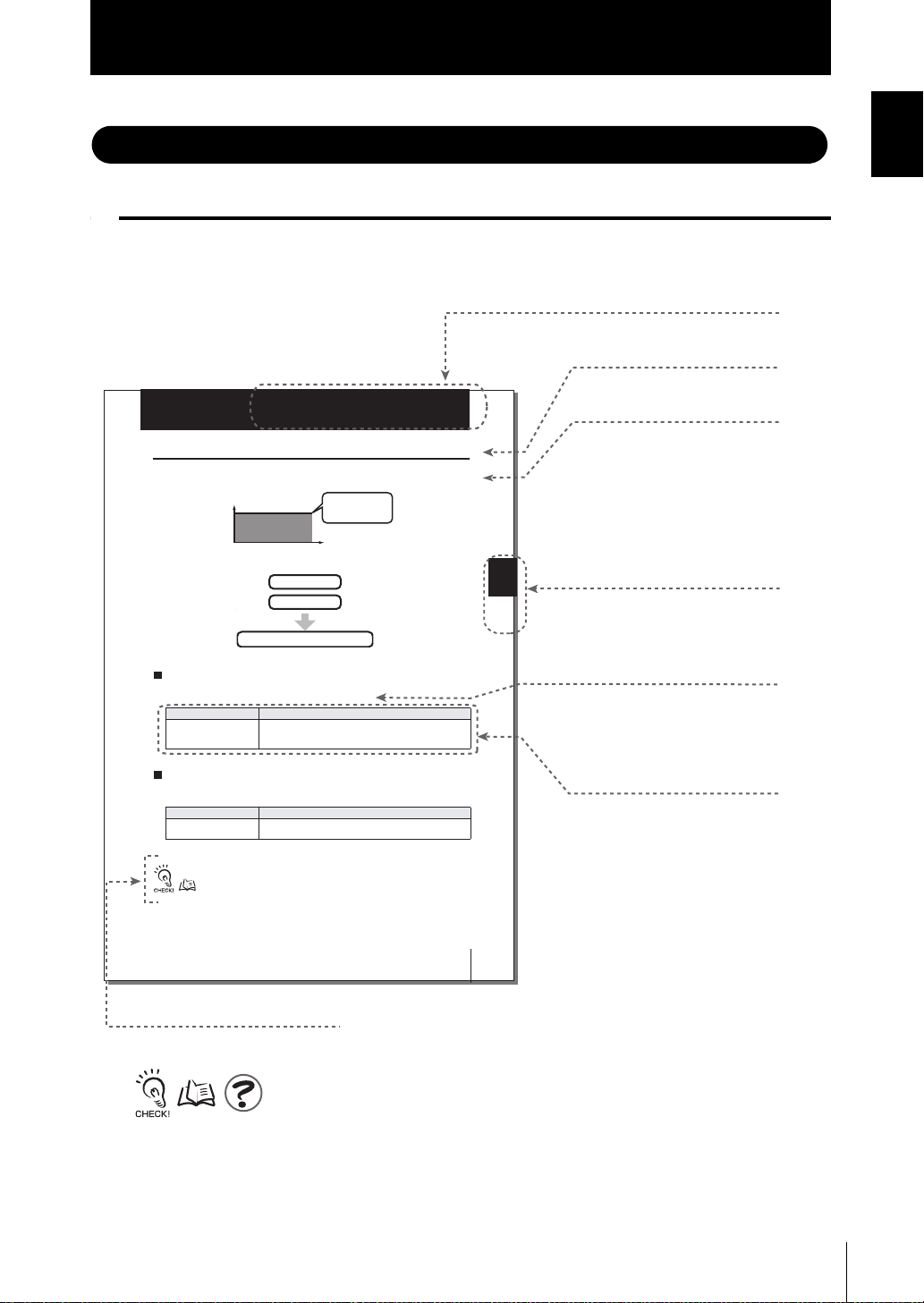
Header
Overview
Title of each section
Index label
Movement through menus
up to setting items
Supplementary Explanation
Helpful information regarding operation and reference
pages are introduced here using symbols.
* This page has been made purely for
explanatory purposes and does not exist.
Explanation of options
Indicates the section
number and title.
Page Format
Setting of the Irradiation Conditions
Setting the Constant Irradiation Conditions
Irradiation power and time are set for the purpose of continually irradiating the UV light
for a certain time with a constant irradiation intensity.
Irradiation power
(%)
Continual irradiation of
the constant UV lights
for a certain time
Introduction
Introduction
Section 3
Setting of the Irradiation Power
FUN Mode-[CH SET]-[1CH to 4CH]-[CONSTANT]-[POWER]
Power Set the UV irradiation intensity. Irradiation power can be set at the
Setting of the Irradiation Time
FUN Mode-[CH SET]-[1CH to 4CH]-[CONSTANT]-[TIME]
TIME Set the Irradiation Time.
For details on the settings, refer to Section 2, "Let's Try Irradiation".
Change to the RUN mode to irradiate with the UV light.
Setting Description
rate when the maximum power setting is 100.
Setting Description
p.2-4
Irradiation time (s)
Setting of the Irradiation Power
Setting of the Irradiation Time
Range: 0 to 100 (by 1%-step) (Default value: 100 %)
Range: 000.0 to 999.9 (S) (Default value: 999.9 S)
Section 3
Setting
ZUV
User's Manual
3-5
ZUV
User’s Manual
11

Introduction
Introduction
■ Meaning of Symbols
Menu items that are displayed on the controller's LCD screen, and window, dialog
boxes and other GUI elements displayed on the PC are indicated enclosed by bracket s
[ ].
■ Visual Aids
Indicates points that are important to ensure full product performance, such as operational
precautions and application procedures.
Indicates pages where related information can be found.
Indicates information helpful in operation.
12
ZUV
User’s Manual
CONTENTS
Introduction
CONTENTS
CONTENTS
Meanings of Signal Words 5
Meanings of Alert Symbols 5
Alert statements in this Manual 6
Precautions for Safe Use 7
Precautions for Correct Use 9
Editor's Note 11
Page Format 11
CONTENTS 13
Section 1
OVERVIEW & INSTALLATION AND CONNECTION 1-1
Basic Configuration 1-2
Part Names and Functions 1-3
Controller 1-3
Head 1-4
Installation & Connection 1-5
Before Installation and Connection 1-5
Installing the Controller 1-5
Section 1 Section 2 Section 3 Section 4 Section 5
Installing the Head 1-6
Connecting Devices 1-8
Section 2
ZUV BASIC OPERATION 2-1
Starting Up and Shutting Down 2-2
Let's Try Irradiation 2-4
Irradiating at Constant Power 2-5
Creating Irradiation Patterns for Irradiation 2-7
Operating Modes 2-11
Function Setting Mode - LOCK mode 2-13
Operation-in-progress Mode - READY Mode 2-15
ZUV
User’s Manual
13

Introduction
CONTENTS
CONTENTS
Section 3
SETUP 3-1
LOCK Mode Setting Item List 3-2
Setting the Irradiation Conditions 3-4
Setting Constant Irradiation Conditions 3-5
Setting Pattern Irradiation 3-6
Copying Irradiation Conditions 3-9
Device Setup Change Setting (Bank) 3-11
Switching Banks 3-12
Copying Banks 3-12
Clearing Banks 3-12
Enabling Bank Switching Input 3-13
Setting/Executing Power Tuning 3-14
Displaying Irradiation Log Data 3-18
Setting Cumulative Alarms 3-19
Setting the System Environment 3-20
Setting Passwords 3-20
Setting the Buzzer Function 3-21
Changing the Display Language 3-21
Setting the I/O Signal Conditions 3-21
Initializing Setting Data 3-22
Checking System Information 3-22
Disabling the Irradiation Buttons 3-22
Setting the Display Method 3-23
Section 4
CONNECTING TO EXTERNAL DEVICES 4-1
Connection by an I/O Terminal Block 4-2
Connection and Communication Settings 4-2
Timing Charts 4-6
Connection by USB/RS-232C 4-9
Connection and Communication Settings 4-9
14
USB Driver 4-11
Communication Commands 4-14
Setting Hyper Terminal 4-37
ZUV
User's manual

Introduction
CONTENTS
Section 5 APPENDIX 5-1
Troubleshooting 5-2
Error Messages and Countermeasures 5-3
Q&A 5-4
Maintenance of the Head 5-4
Cleaning the Lens Unit 5-4
Replacing the Lens Unit 5-5
Specifications and External Dimensions 5-6
Controller 5-6
Requirements from Regulations and Standards 5-8
Summary of Requirements to Manufactures 5-8
Summary of Requirements to User 5-10
Definitions of Laser Classification 5-11
INDEX 5-13
CONTENTS
Section 1 Section 2 Section 3 Section 4 Section 5
Revision History 5-16
ZUV
User’s Manual
15

Introduction
CONTENTS
CONTENTS
MEMO
16
ZUV
User's manual
Section 1 OVERVIEW & INSTALLATION AND CONNECTION
Basic Configuration 1-2
Part Names and Functions 1-3
Controller 1-3
Head 1-4
Installation & Connection 1-5
Before Installation and Connection 1-5
Installing the Controller 1-5
Installing the Head 1-6
Connecting Devices 1-8
Section 1 OVERVIEW & INSTALLATION AND CONNECTION
ZUV
User’s Manual
1-1
Section 1
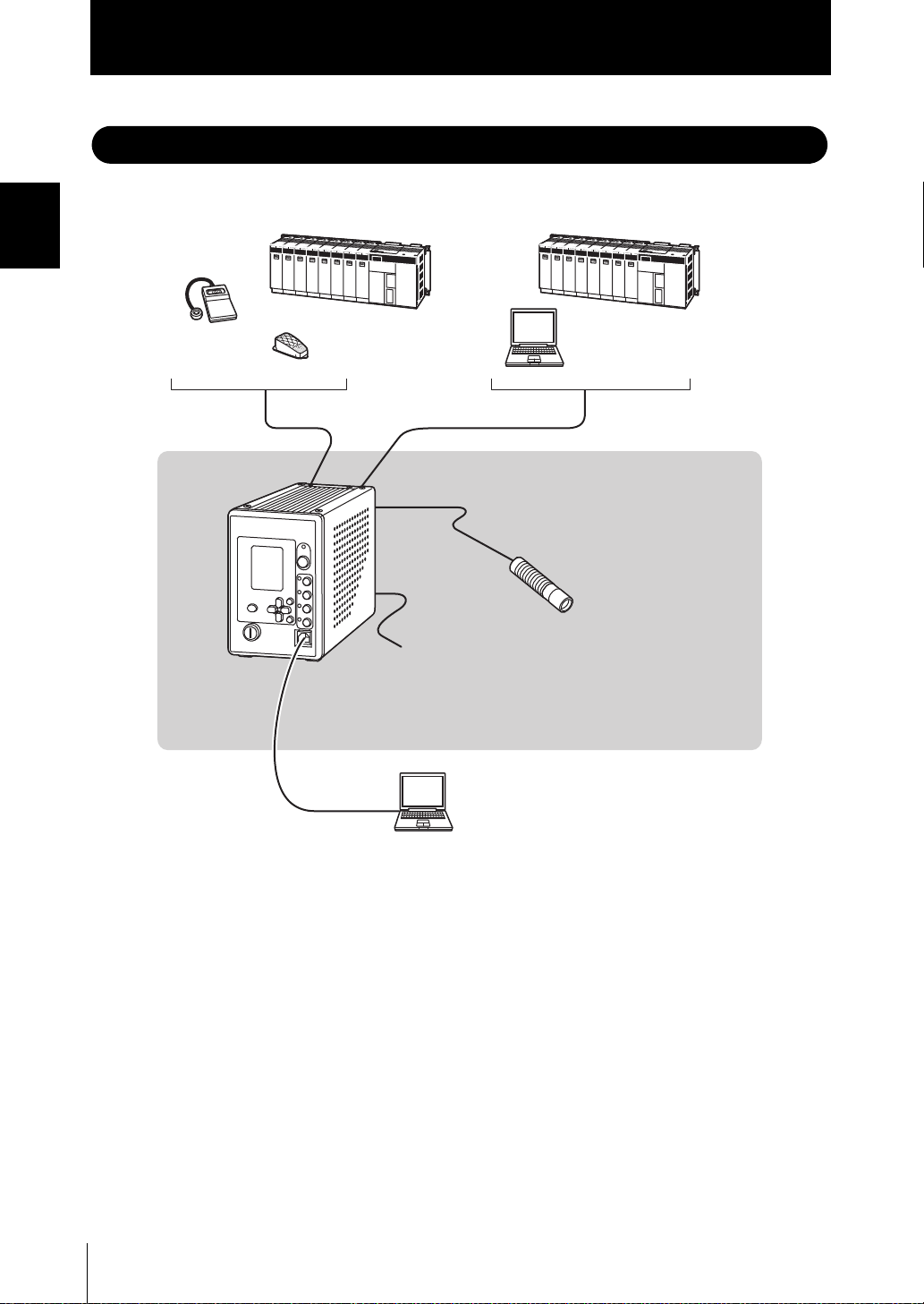
Programmable
controller
Programmable
controller
Personal computer
Personal computer
Foot switch
External I/O
RS-232C cable
USB cable
Controller
Head
Power supply
Select AC or DC power supply.
• AC power supply: AC adapter is used (supplied with the product)
• DC power supply: supplied from the terminal block on the rear
Recommended power supply unit:
S8VS-18024 (24 VDC 7.5A) by OMRON
UV luxmeter
Basic Configuration
Basic Configuration
Section 1 OVERVIEW & INSTALLATION AND CONNECTION
The figure below shows the basic configuration of the ZUV.
1-2
ZUV
User’s Manual
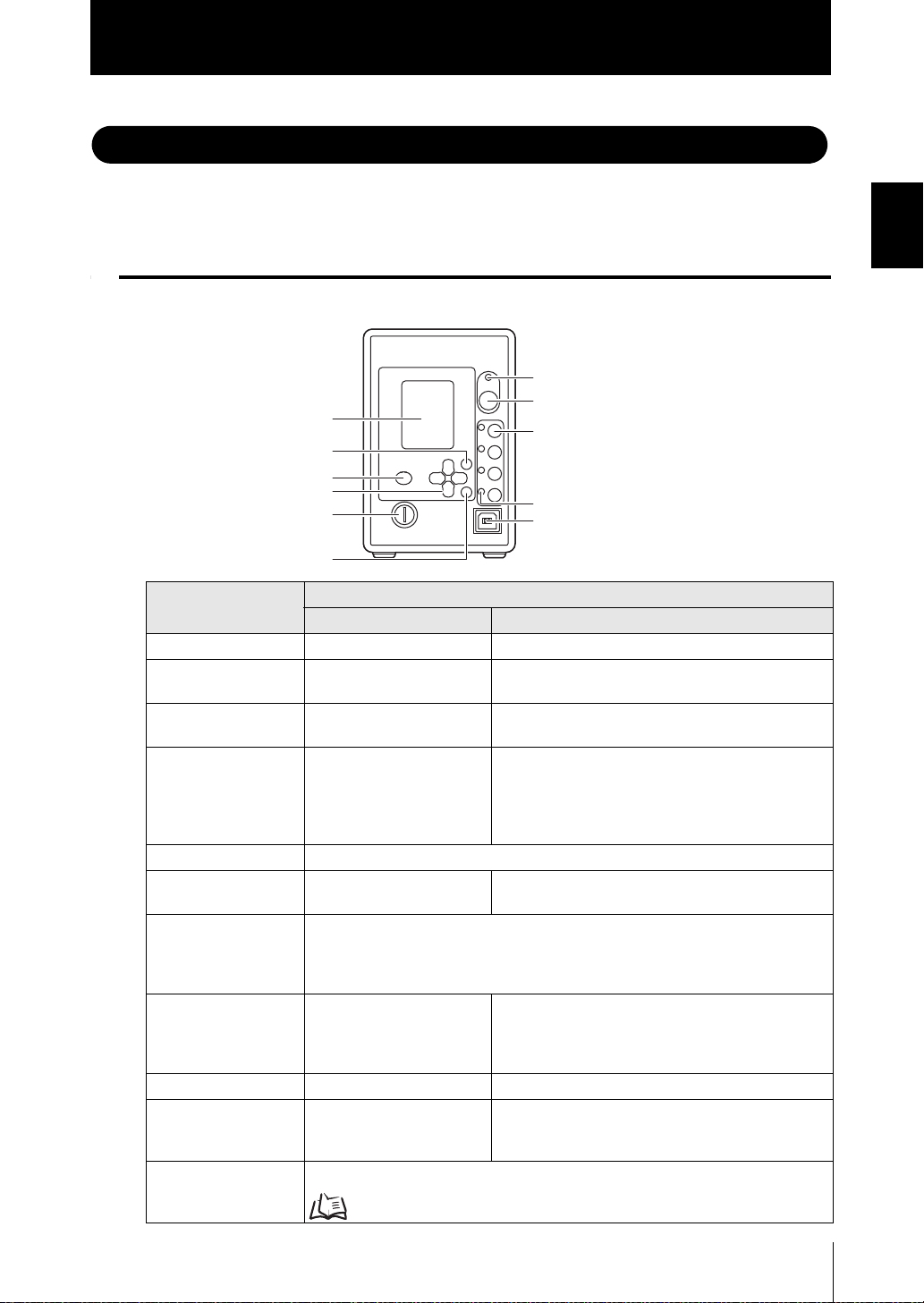
Part Names and Functions
(1) UV ON indicator
(4) UV READY indicator
(5) USB port
(6) SET key
(7) Key switch
(8) Control keys
(9) MENU key
(10) ESC key
(11) LCD screen
(2) EMISSION button
(3) CH1 to CH4 buttons
Section 1
Part Names and Functions
This section describes the names and functions of parts on the controller and head.
Controller
■ Front
Name
(1) UV ON indicator Goes out. Lights during UV irradiation.
(2) EMISSION
button
(3) CH1 to CH4
buttons
(4) UV READY
indicator
(5) USB port Connect the USB cable to the USB port to connect to a personal computer.
(6) SET key Selects and applies items
(7) Key switch Operating this key switches between the LOCK and READY modes.
(8) Control keys Move the cursor and
(9) MENU key Saves settings. —
(10) ESC key Cancels the setting, and
(11) LCD screen Displays a display screen or setting menu during operation.
LOCK Mode READY Mode
— Pressing this button starts/stops UV light irradiation
— The head corresponding to the pressed button
Goes out. Lights in the irradiation standby mode when the key
when they are being set.
LOCK mode: Irradiation conditions can be set in this mode.
Irradiation is disabled.
READY mode: Irradiation is enabled in this mode.
change numeric values.
returns to the one previous
menu.
Operating Modes p.2-11
Function
from the irradiation standby head.
starts/stops UV light irradiation.
switch is turned to the "READY" position. Note that
the indicator goes out during UV irradiation.
The channel corresponding to the connected head
lights.
—
The ← → L/R keys change the display screen during
operation.
The ↑ ↓ UP/DOWN keys change the display
channel.
—
User’s Manual
Section1 OVERVIEW & INSTALLATION AND CONNECTION
ZUV
1-3
Section 1
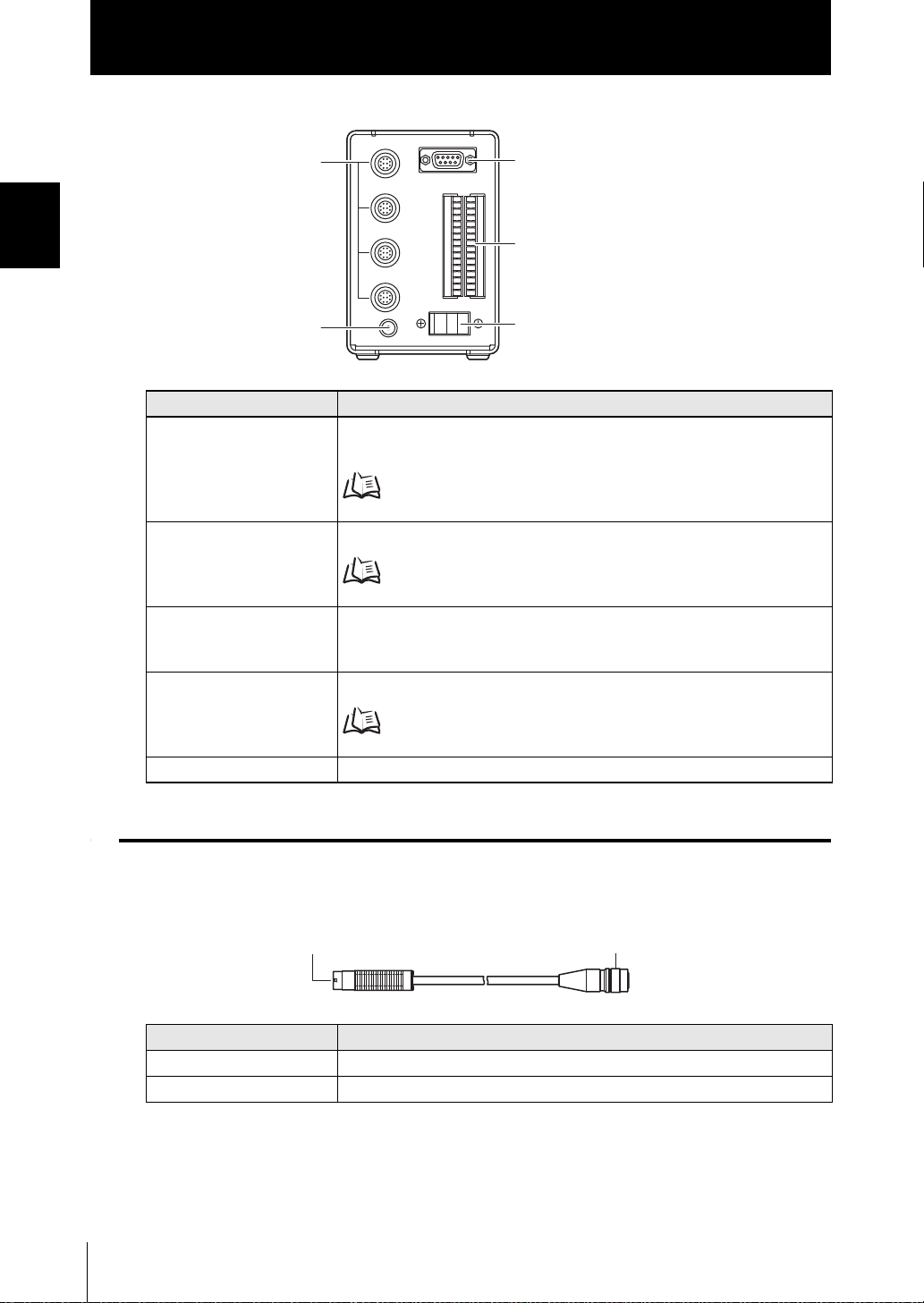
(1) RS-232C connector
(2) I/O terminal block
(3) Power supply switch
(4) AC adapter jack
(5) Head connector
(1) UV irradiation nozzle
(2) Connector
ZUV-H series
Part Names and Functions
■ Rear
Section 1 OVERVIEW & INSTALLATION AND CONNECTION
Name Function
(1) RS-232C connector Connects to the personal computer or programmable controller via the serial
cable to control input from external devices.
p.4-10
(2) I/O terminal block Connects external devices such as the foot switch.
p.4-2
(3) Power supply switch Switches the main power supply ON/OFF.
The ON/OFF direction differs between the AC power supply and the DC
power supply. Check the ON/OFF direction printed on the main unit.
(4) AC adapter jack Connects to the AC power supply.
p.1-8
(5) Head connector Connects to the head.
Head
Name Function
(1) UV irradiation nozzle UV light is irradiated from this nozzle.
(2) Connector Connects to the controller.
1-4
ZUV
User’s Manual
Section 1
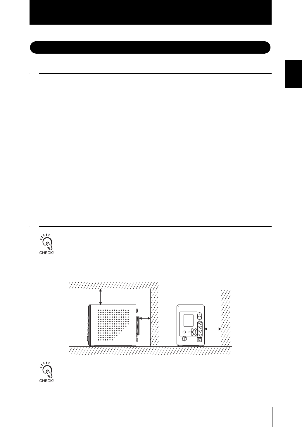
80 mm
50 mm
80 mm
Front
Rear
Installation & Connection
Installation & Connection
Before Installation and Connection
■ Checking the installation environment
Read "Precautions for Safe Use" at the beginning of this manual, and check the
installation environment.
■ Checking the installation site
Read "Precautions for Correct Use" at the beginning of this manual, and check the
installation site.
■ Power supply
Before installing and connecting the controller, be sure to turn it OFF.
Also read "Precautions for Safe Use" and "Precautions for Correct Use" at the
beginning of this manual, and check the power supply and wiring.
Section1 OVERVIEW & INSTALLATION AND CONNECTION
Installing the Controller
Before connecting/disconnecting peripheral devices, make sure that the controller is turned OFF.
Maintain sufficient space around the controller for installation.
Do not install multiple controllers close to others, or do not pile them up.
ZUV
User’s Manual
1-5
Section 1
Installation & Connection
Installing the Head
Section 1 OVERVIEW & INSTALLATION AND CONNECTION
Never look directly at or allow your skin to be exposed to the
ultraviolet light.
To prevent exposure to ultraviolet light, never look into the ultraviolet
light.
Workers should wear protective goggles and equipment to protect from being
exposed to reflected light.
Electric shock or light leakage may cause injury.
Do not disassemble the product.
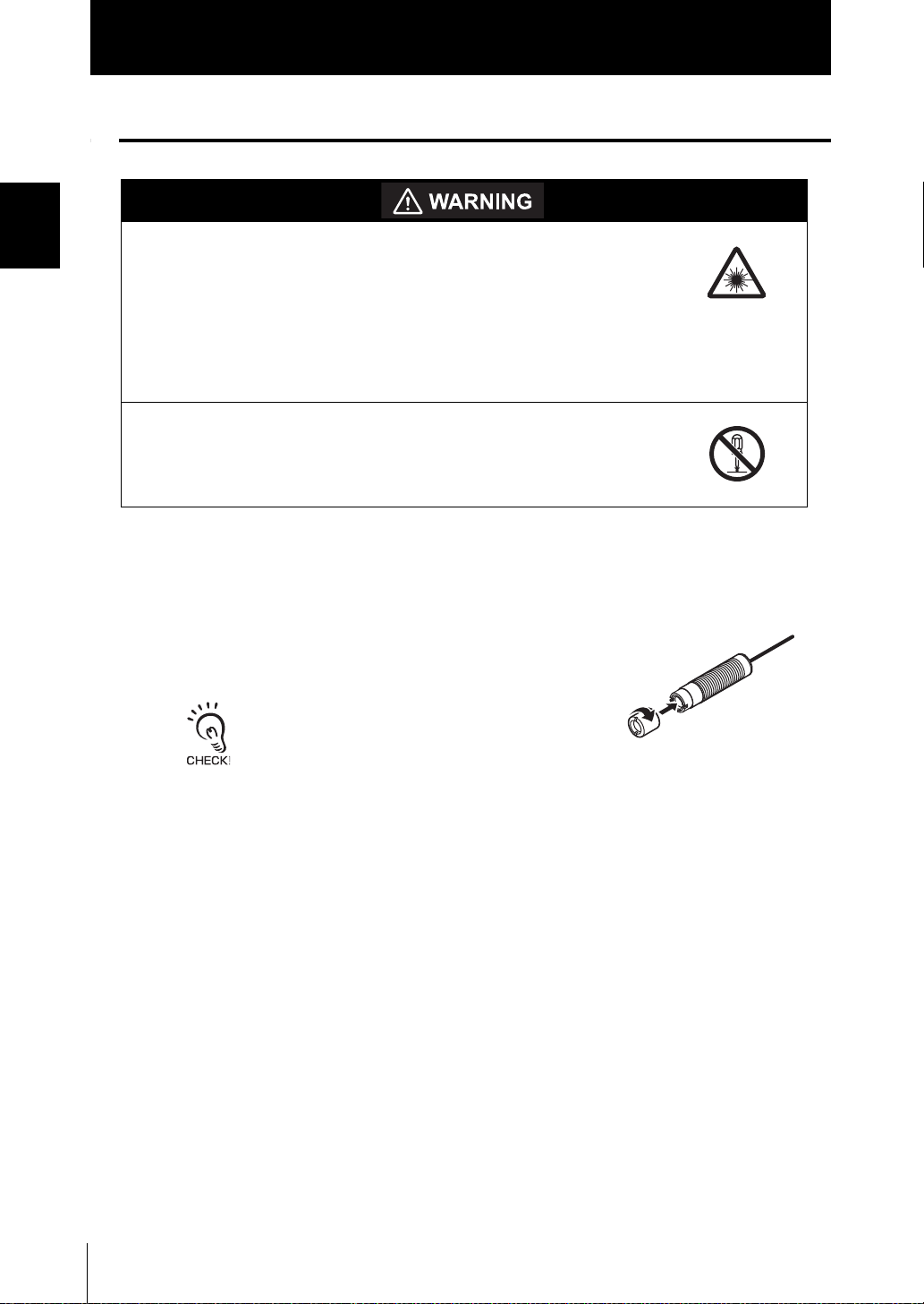
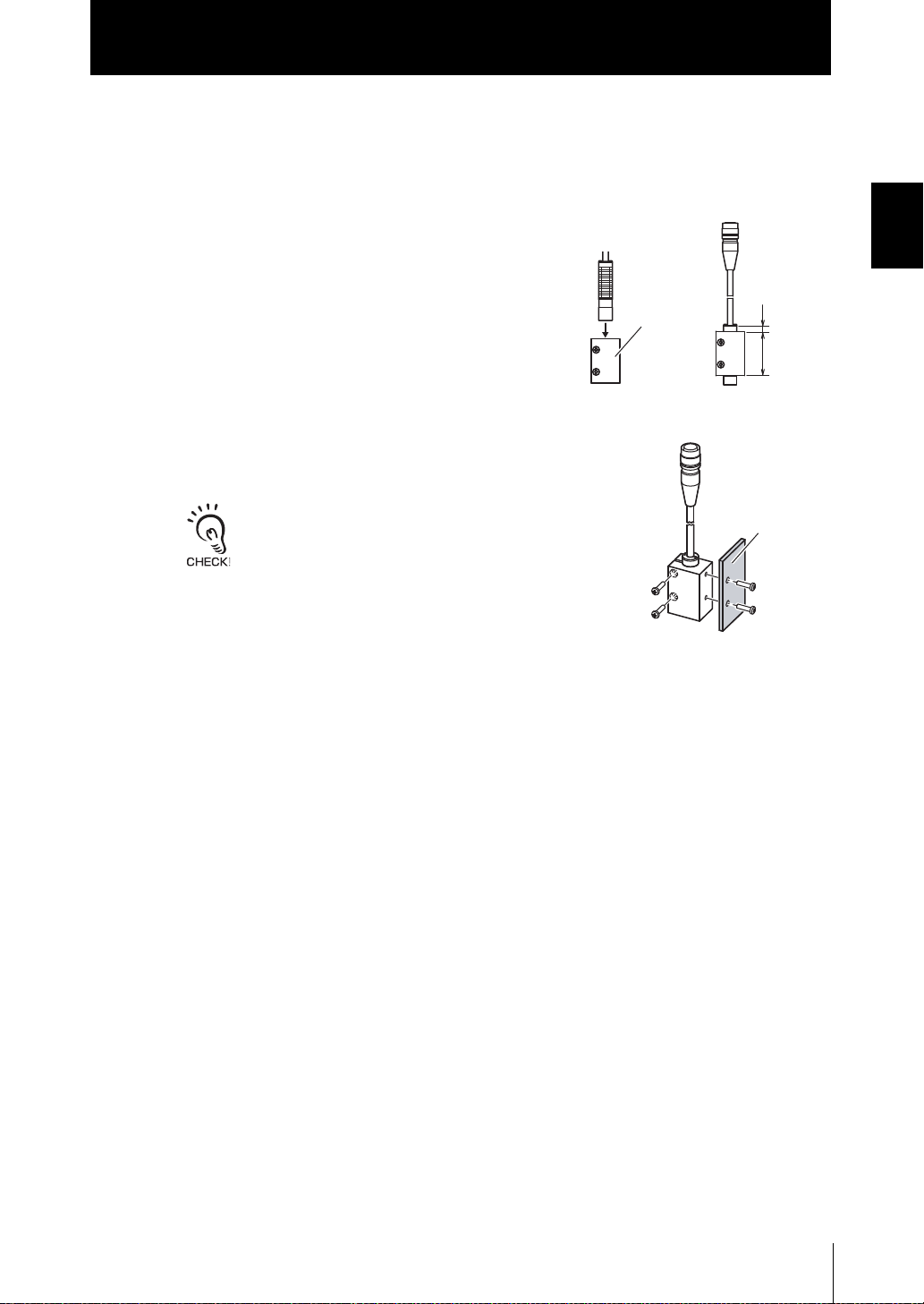
■ Installing the head unit and lens unit
1. To install the lens unit, screw it into the head
unit.
Tightening torque: 0.2 N•m
• Screws may be damaged if the torque is outside the
specifications.
• Other lens units cannot be installed on head unit
ZUV-H40M since a fixed type exclusive lens is
attached.
1-6
ZUV
User’s Manual
Installation & Connection
Mounting
bracket
(Unit: mm)
40
6
Jig
M3 screws
M4 screws
■ Connecting the Head
Install the head using the mounting bracket supplied with the head.
Section 1
1. Insert the head into the mounting bracket.
2. Fix the head to the mounting bracket.
Screws: M3 x 2
Tightening torque: 0.9 N•m or more to 1.5 N•m or less
Be sure to use the screws supplied with the head.
3. Fix the mounting bracket to the jig.
Screws: M4 x 2
Tightening torque: 1.2 N•m
Section1 OVERVIEW & INSTALLATION AND CONNECTION
ZUV
User’s Manual
1-7
Section 1
Installation & Connection
Connecting Devices
Section 1 OVERVIEW & INSTALLATION AND CONNECTION
Never look directly at or allow your skin to be exposed to the
ultraviolet light.
To prevent exposure to ultraviolet light, never look into the ultraviolet
light.
Workers should wear protective goggles and equipment to protect them from being
exposed to reflected light.
Electric shock or light leakage may cause injury.
Do not disassemble the product.
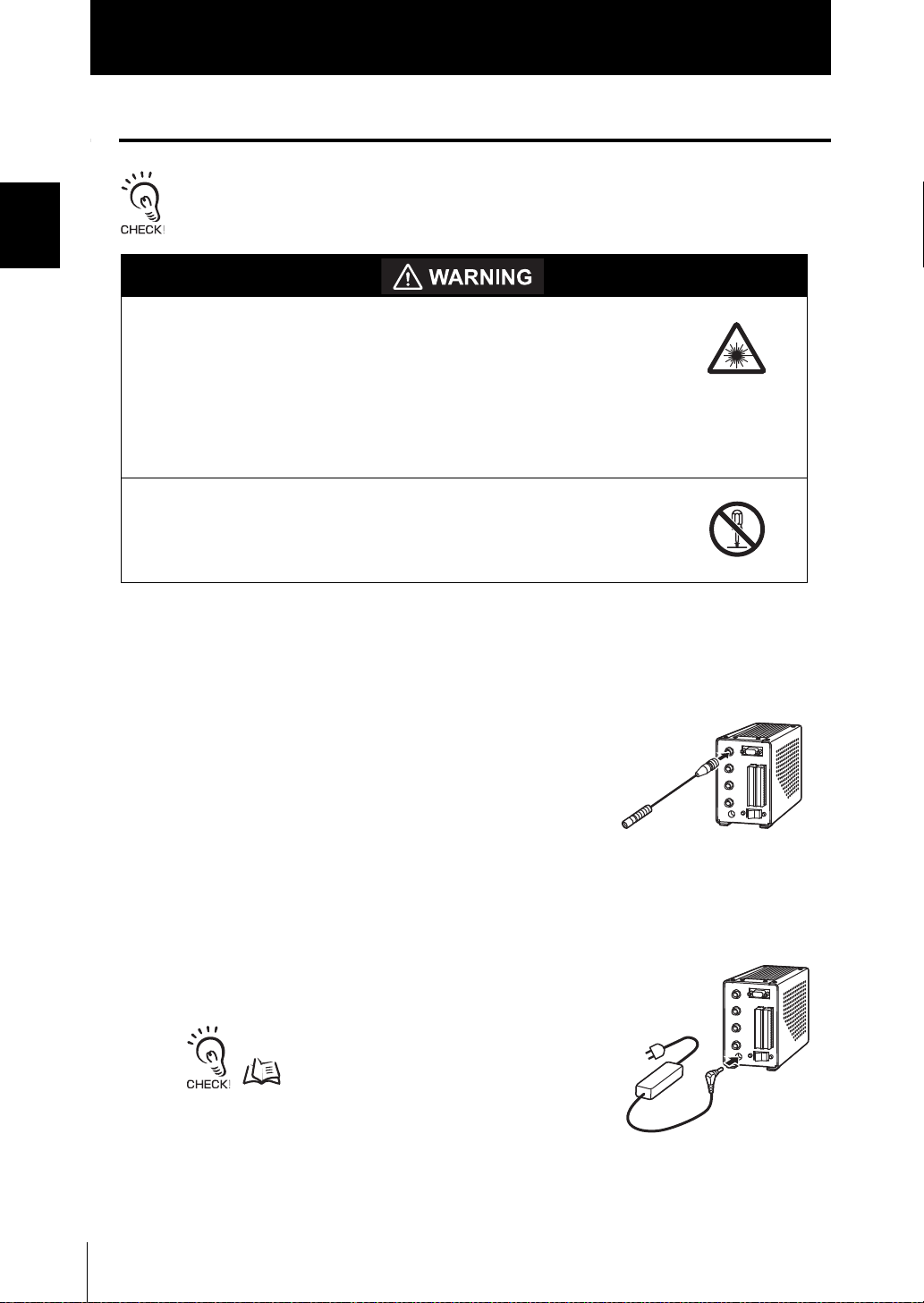
■ Connecting the head
• Before connecting/disconnecting peripheral devices, make sure that the controller is turned OFF.
• For details on connecting external devices, see "Section 4 CONNECTING TO EXTERNAL DEVICES."
1. Insert the head connector to the head
connector on the controller rear by aligning
the female and male pins of each side of the
connectors.
■ Connecting the AC Adapter
1. Connect the AC power supply cable to the AC
adapter jack on the controller rear.
The DC power supply can also be used.
Wiring p.4-3
1-8
ZUV
User’s Manual
Section 2 ZUV BASIC OPERATION
Starting Up and Shutting Down 2-2
Let's Try Irradiation 2-4
Irradiating at Constant Power 2-5
Creating Irradiation Patterns for Irradiation 2-7
Operating Modes 2-11
Function Setting Mode - LOCK mode 2-13
Operation-in-progress Mode - READY Mode 2-15
Section 2 ZUV BASIC OPERATION
ZUV
User’s Manual
2-1
Section 2
Starting Up and Shutting Down
Starting Up and Shutting Down
Section 2 ZUV BASIC OPERATION
Never look directly at or allow your skin to be exposed to the
ultraviolet light.
To prevent exposure to ultraviolet light, never look into the ultraviolet
light.
Workers should wear protective goggles and equipment to protect them from being
exposed to reflected light.
Electric shock or light leakage may cause injury.
Do not disassemble the product.
• Before turning ON the power supply confirm that the controller and head are properly connected.
• Remove the key from the key switch when the controller is not in operation.
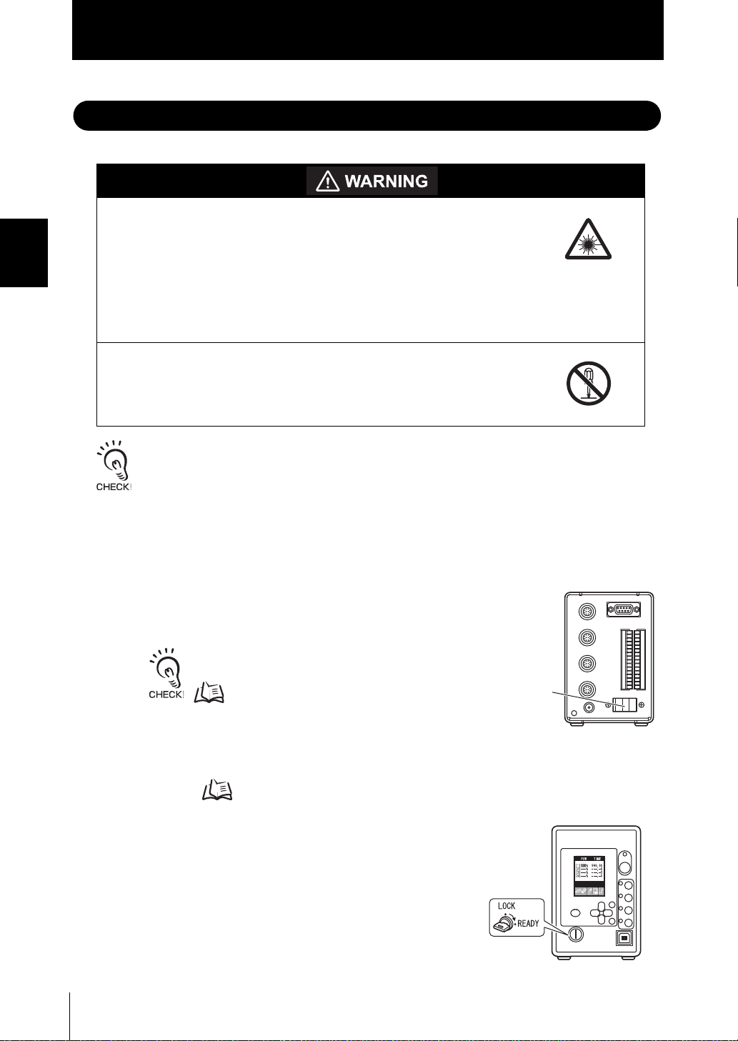
■ Starting Up
1. Check that the key switch on the controller front is set to the LOCK posit ion.
2. Set the power switch on the controller rear to
ON.
2-2
• The ON/OFF direction differs between the AC
power supply and the DC power supply.
p.1-4
• The Japanese-to-English selection message is
displayed only at initial startup.
• When the password function is enabled, the
password must be entered.
p.2-11
3. Insert the key in the key switch on the
controller front and turn it to the [READY]
position when the LOCK mode top menu is
displayed.
The ZUV enters the irradiation ready mode.
In addition, the UV READY indicator on the head, which
is in the irradiation ready mode, lights up when the
mode is switched to the READY mode.
ZUV
User’s Manual
Power supply
switch
Section 2
Power supply
switch
Starting Up and Shutting Down
■ Shutting Down
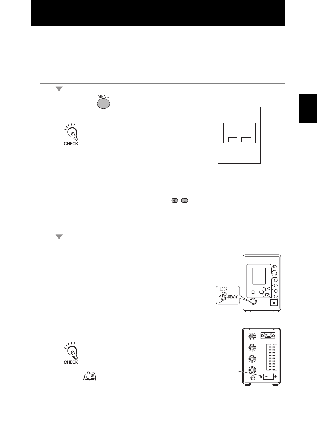
Save the setting data before turning OFF the power supply . All settings will be deleted if
you turn the power OFF without saving the data.
Saving the setting data
1. Press the key to save setting data.
The save confirmation message is displayed.
SAVE
The save confirmation message is displayed when
the mode is switched to the READY mode without
saving the setting data using the MENU key. The
save confirmation message is displayed only when
the settings have been changed. Otherwise, it is not
displayed.
SETTING DATA
EXE CAN
Section 2 ZUV BASIC OPERATION
2. Move the cursor to [EXE] using the keys, and press the SET key.
Turning OFF the powe r
3. Turn the key of the key switch on the
controller front to the [LOCK] position.
4. Set the power switch on the controller rear to
OFF.
• Remove the key from the key switch when the
controller is not restarted.
• The ON/OFF direction differs between the AC
power supply and the DC power supply.
p.1-4
ZUV
User’s Manual
2-3
Section 2 ZUV BASIC OPERATION
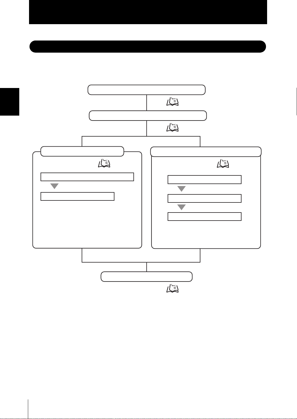
Confirmation of Installation and Connection
Starting Up and Shutting Down
Installation & Connection
Starting Up
Setting the Irradiation Power and Time
Irradiating UV Light
Irradiating at Constant Power
Creating Irradiation Patterns
Selecting Irradiation Patterns
Irradiating with UV Light
Creating Irradiation Patterns for Irradiation
Starting Up and Shutting Down
Shutting Down
p.1-5
p.2-2
p.2-5
p.2-7
p.2-2
Section 2
Let's Try Irradiation
Let's Try Irradiation
This section describes the basic operating procedures from setting the irradiation
conditions up to performing constant irradiation or pattern irradiation.
2-4
ZUV
User’s Manual
 Loading...