


USER’S MANUAL
Smart Sensors
Multi-Controller
ZS-MDC (Ver 2.0)
Cat.No. Z209-E2-01

Introduction
‚Í‚¶‚ß‚É ‘æ 1 Í‘æ 2 Í‘æ 3 Í‘æ 4 Í
INTRODUCTION
SECTION 1
SECTION 2
SECTION 3
SECTION 4
SECTION 5
APPLICATION CONSIDERATIONS (Please Read)
Section 1 Section 2 Section 3 Section 4 Section 5
FEATURES
INSTALLATION & CONNECTION
SETUP
APPLICATION SETTING EXAMPLES
APPENDIX
ection
User's Manual
Smart Sensors
Multi-Controller ZS-MDC

Introduction
Introduction
READ AND UNDERSTAND THIS DOCUMENT
Please read and understand this document before using the products. Please consult your OMRON
representative if you have any questions or comments.
WARRANTY
OMRON’s exclusive warranty is that the products are free from defects in materials and workmanship for
a period of one year (or other period if specified) from date of sale by OMRON.
OMRON MAKES NO WARRANTY OR REPRESENTATION, EXPRESS OR IMPLIED, REGARDING
NON-INFRINGEMENT, MERCHANTABILITY, OR FITNESS FOR PARTICULAR PURPOSE OF THE
PRODUCTS. ANY BUYER OR USER ACKNOWLEDGES THAT THE BUYER OR USER ALONE HAS
DETERMINED THAT THE PRODUCTS WILL SUITABLY MEET THE REQUIREMENTS OF THEIR
INTENDED USE. OMRON DISCLAIMS ALL OTHER WARRANTIES, EXPRESS OR IMPLIED.
LIMITATIONS OF LIABILITY
OMRON SHALL NOT BE RESPONSIBLE FOR SPECIAL, INDIRECT, OR CONSEQUENTIAL
DAMAGES, LOSS OF PROFITS OR COMMERCIAL LOSS IN ANY WAY CONNECTED WITH THE
PRODUCTS, WHETHER SUCH CLAIM IS BASED ON CONTRACT, WARRANTY, NEGLIGENCE, OR
STRICT LIABILITY.
In no event shall responsibility of OMRON for any act exceed the individual price of the product on which
liability is asserted.
IN NO EVENT SHALL OMRON BE RESPONSIBLE FOR WARRANTY, REPAIR, OR OTHER CLAIMS
REGARDING THE PRODUCTS UNLESS OMRON’S ANALYSIS CONFIRMS THAT THE PRODUCTS
WERE PROPERLY HANDLED, STORED, INSTALLED, AND MAINTAINED AND NOT SUBJECT TO
CONTAMINATION, ABUSE, MISUSE, OR INAPPROPRIATE MODIFICATION OR REPAIR.
2
ZS-MDC
User’s Manual

Introduction
SUITABILITY FOR USE
THE PRODUCTS CONTAINED IN THIS DOCUMENT ARE NOT SAFETY RATED. THEY ARE NOT
DESIGNED OR RATED FOR ENSURING SAFETY OF PERSONS, AND SHOULD NOT BE RELIED
UPON AS A SAFETY COMPONENT OR PROTECTIVE DEVICE FOR SUCH PURPOSES.
Please refer to separate catalogs for OMRON’s safety rated products.
OMRON shall not be responsible for conformity with any standards, codes, or regulations that apply to
the combination of products in the customer’s application or use of the product.
At the customer’s request, OMRON will provide applicable third party certification documents identifying
ratings and limitations of use that apply to the products. This information by itself is not sufficient for a
complete determination of the suitability of the products in combination with the end product, machine,
system, or other application or use.
The following are some examples of applications for which particular attention must be given. This is not
intended to be an exhaustive list of all possible uses of the products, nor is it intended to imply that the
uses listed may be suitable for the products:
• Outdoor use, uses involving potential chemical contamination or electrical interference, or conditions or
uses not described in this document.
• Nuclear energy control systems, combustion systems, railroad systems, aviation systems, medical
equipment, amusement machines, vehicles, safety equipment, and installations subject to separate
industry or government regulations.
• Systems, machines, and equipment that could present a risk to life or property.
Introduction
Please know and observe all prohibitions of use applicable to the products.
NEVER USE THE PRODUCTS FOR AN APPLICATION INVOLVING SERIOUS RISK TO LIFE OR
PROPERTY WITHOUT ENSURING THAT THE SYSTEM AS A WHOLE HAS BEEN DESIGNED TO
ADDRESS THE RISKS, AND THAT THE OMRON PRODUCT IS PROPERLY RATED AND INSTALLED
FOR THE INTENDED USE WITHIN THE OVERALL EQUIPMENT OR SYSTEM.
PERFORMANCE DATA
Performance data given in this document is provided as a guide for the user in determining suitability and
does not constitute a warranty. It may represent the result of OMRON’s test conditions, and the users
must correlate it to actual application requirements. Actual performance is subject to the OMRON
Warranty and Limitations of Liability.
CHANGE IN SPECIFICATIONS
Product specifications and accessories may be changed at any time based on improvements and other
reasons.
It is our practice to change model numbers when published ratings or features are changed, or when
significant construction changes are made. However, some specifications of the product may be
changed without any notice. When in doubt, special model numbers may be assigned to fix or establish
key specifications for your application on your request. Please consult with your OMRON representative
at any time to confirm actual specifications of purchased products.
ZS-MDC
User’s Manual
3

Introduction
Introduction
DIMENSIONS AND WEIGHTS
Dimensions and weights are nominal and are not to be used for manufacturing purposes, even when
tolerances are shown.
ERRORS AND OMISSIONS
The information in this document has been carefully checked and is believed to be accurate; however, no
responsibility is assumed for clerical, typographical, or proofreading errors, or omissions.
PROGRAMMABLE PRODUCTS
OMRON shall not be responsible for the user’s programming of a programmable product, or any
consequence thereof.
COPYRIGHT AND COPY PERMISSION
This document shall not be copied for sales or promotions without permission.
This document is protected by copyright and is intended solely for use in conjunction with the product.
Please notify us before copying or reproducing this document in any manner, for any other purpose. If
copying or transmitting this document to another, please copy or transmit it in its entirety.
4
ZS-MDC
User’s Manual

Precautions for Safe Use
Precautions for Safe Use
Please observe the following precautions for safe use of the products.
(1) Installation Environment
• Do not use the product in environments where it can be exposed to inflammable/
explosive gas.
• To secure the safety of operation and maintenance, do not install the product close to
high-voltage devices and power devices.
(2) Power Supply and Wiring
• The supply voltage must be within the rated range (DC24V±10%).
• Reverse connection of the power supply is not allowed.
• Open-collector outputs should not be short-circuited.
• Use the power supply within the rated load.
• High-voltage lines and power lines must be wired separately from this product. Wiring
them together or placing them in the same duct may cause induction, resulting in malfunction or damage.
Introduction
Introduction
(3) Others
• Do not attempt to dismantle, repair, or modify the product.
• Dispose of this product as industrial waste.
ZS-MDC
User’s Manual
5

Introduction
Introduction
Precautions for Correct Use
Precautions for Correct Use
Please observe the following precautions to prevent failure to operate, malfunctions, or
undesirable effects on product performance.
(1) Installation Site
Do not install the product in locations subjected to the following conditions:
• Ambient temperature outside the rating
• Rapid temperature fluctuations (causing condensation)
• Relative humidity outside the range of 35 to 85%
• Presence of corrosive or flammable gases
• Presence of dust, salt, or iron particles
• Direct vibration or shock
• Reflection of intense light (such as other laser beams or electric arc-welding
machines)
• Direct sunlight or near heaters
• Water, oil, or chemical fumes or spray
• Strong magnetic or electric field
(2) Power Supply and Wiring
• When using a commercially available switching regulator, make sure that the FG terminal is grounded.
• If surge currents are present in the power lines, connect surge absorbers that suit the
operating environment.
• Before turning ON the power after the product is connected, make sure that the power
supply voltage is correct, there are no incorrect connections (e.g. load short-circuit)
and the load current is appropriate. Incorrect wiring may result in breakdown of the
product.
• Before connecting/disconnecting the Peripheral device, make sure that the Multi-Controller is turned OFF. The Multi-Controller may break down if the Peripheral device is
connected or disconnected while the power is ON.
• Use only combinations with Sensor Controllers specified in this manual.
6
ZS-MDC
User’s Manual
(3) Orientation when Installing the Multi-Controller
To improve heat radiation, install the Multi-Controller only in the
orientation shown below.
Right
Do not install the Multi-Controller in the following orientations.
Wrong Wrong
Introduction
Precautions for Correct Use
Introduction
(4) Warming Up
After turning ON the power supply, allow the product to stand for at least 30 minutes
before use. The circuits are still unstable immediately after the power supply is turned
ON, so measured values may fluctuate gradually.
(5) Maintenance and Inspection
Do not use thinner, benzene, acetone or kerosene to clean the Multi-Controller.
ZS-MDC
User’s Manual
7
Introduction
Introduction
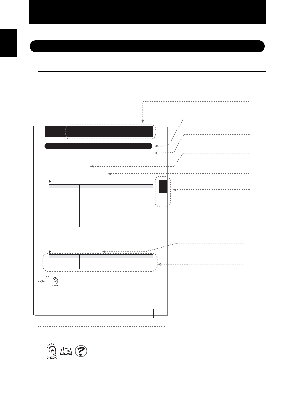
Editor's Note
Editor's Note
Page Format
Title of each section
Header
Setting the Sensor Controller to Obtain Sensing Information from
Section 3
Setting the Sensor Controller to Obtain Sensing Information from
Set which gang-mounted Sensor Controller to obtain information from, and which logic
operations are to be performed on that information.
Setting Assignments
Assign the channel to perform logic operation on.
FUNMode-[SENSIN SEL CHG]-[ ]
Setting Description
INPUT A (input A) Assigns the target Sensor Controller to input A.
INPUT B (input B) Assigns the target Sensor Controller to input B.
INPUT C (input C) Assigns the target Sensor Controller to input C.
INPUT D (input D) Assigns the target Sensor Controller to input D.
Setting Logic Operation Methods
Set how logic operations are to be performed on the tasks and CH specified by the
assignment settings.
FUNMODE-[SENSING]-[CALC]
Setting Description
OFF Expressions are not set.
CH Logic operations are not performed, and the measured value of a specific CH
Inputs do not undergo logical operation when “None” is set. Example: The operation “-B” is per-
formed when “None” is set to input A, “3CH” is assigned to input B and A-B is selected.
Range: None, 1CH onwards (largest CH of gang-mounted Sensor Controllers)
(default: 1CH. Note that range becomes “None” if 1CH does not exist.)
Range: None, 1CH onwards (largest CH of gang-mounted Sensor Controllers)
(default: 2CH. Note that range becomes “None” if 2CH does not exist.)
Range: None, 1CH onwards (largest CH of gang-mounted Sensor Controllers)
(default: 3CH. Note that range becomes“None” if 3CH does not exist.)
Range: None, 1CH onwards (largest CH of gang-mounted Sensor Controllers)
(default: 4CH. Note that range becomes “None” if 4CH does not exist.)
is input as it is.Select the targ
et CH.
Section 3 SETUP
Overview
Cross-header
Overview of the
cross-header
Index label
Indicates the section
number and title.
Movement
through menus up
to setting items
Explanation of
options
8
Supplementary Explanation
Helpful information regarding operation and reference
pages are introduced here using symbols.
*This page has been made purely for explanatory purposes and does not exist.
ZS-MDC
User’s Manual
ZS-MDC
User’s Manual
3-15

Introduction
Editor's Note
■ Meaning of Symbols
Menu items that are displayed on the Multi-Controller LCD screen, and windows, dialog
boxes and other GUI elements displayed on the PC are indicated enclosed by brackets
[aa].
■ Visual Aids
Indicates points that are important to ensure full product performance, such as operational
precautions and application procedures.
Indicates pages where related information can be found.
Indicates information helpful in operation.
Introduction
ZS-MDC
User’s Manual
9

Introduction
Introduction
Editor's Note
MEMO
10
ZS-MDC
User’s Manual

Contents
Introduction
Contents
Introduction
Precautions for Safe Use 5
Precautions for Correct Use 6
Editor's Note 8
Page Format 8
Contents 11
Section 1 FEATURES 1-1
Multi-Controller Features 1-2
Multi-Controller Applications 1-4
Basic Configuration 1-7
Part Names and Functions 1-8
Section 2 INSTALLATION & CONNECTION 2-1
About Installation and Connection 2-2
Multi-Controller 2-3
Attaching the ferrite core 2-3
Installing the Multi-Controller 2-4
Section 1 Section 2 Section 3 Section 4 Section 5
About the I/O cable 2-10
Section 3 SETUP 3-1
Setting Flow 3-2
About Setup 3-4
Basic Knowledge for Operation 3-4
List of Setting Items 3-9
Selecting Tasks 3-13
Setting the Sensor Controller to Obtain Sensing Information from 3-14
Setting Assignments 3-14
Setting Logic Operation Methods 3-15
Setting I/O Assignments 3-16
Switching banks by external signal input 3-16
Changing Output Assignments 3-17
Changing Linear Output Assignments 3-17
About Digital Output 3-17
ZS-MDC
User’s Manual
11

Introduction
Introduction
Contents
Section 4 APPLICATION SETTING EXAMPLES 4-1
Measuring the Thickness of Multiple Points (sandwiched thickness) 4-2
Measuring the Relative Difference between Steps 4-5
Measuring the Reference Difference between Steps 4-8
Measuring Flatness 4-10
Measuring the Average Height 4-12
Measuring the Twist of a Workpiece 4-14
Measuring the Warp of a Workpiece 4-17
Section 5 APPENDIX 5-1
Troubleshooting 5-2
Error Messages and Countermeasures 5-3
Q&A 5-4
Glossary 5-5
Specifications and External Dimensions 5-6
Multi-Controller 5-6
Panel Mount Adapters 5-9
RS-232C Cable for Connecting to a Personal Computer 5-10
Controller Link Unit 5-11
Version Up Information 5-12
Index 5-13
Revision History 5-16
12
ZS-MDC
User’s Manual

Section 1
FEATURES
Multi-Controller Features 1-2
Multi-Controller Applications 1-4
Basic Configuration 1-7
Part Names and Functions 1-8
Section 1 FEATURES
ZS-MDC
User’s Manual
1-1
Section 1
p
r
Multi-Controller Features
Multi-Controller Features
Section 1 FEATURES
Personal Com
The Multi-Controller is a dedicated controller that gets and performs logical operations on
data obtained from multiple Sensor Controllers. This Multi-Controller features completely
digital-based, data corruption-free logic operation capabilities, and outstanding operability
and convenience.
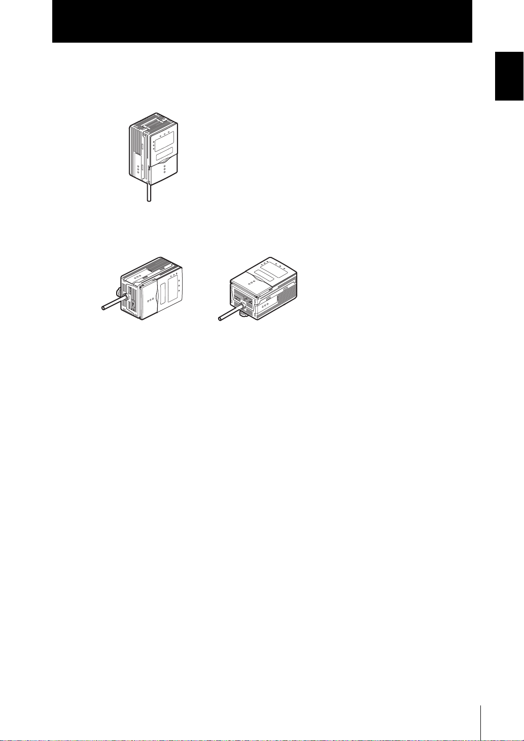
Multi-Controller
Sensor Controllers
ute
(1) Supports Connection to Up to 9 Sensor Controllers
Logic operations can be performed on gang-mounted controllers. Information can be
collected and logic operations performed on information from up to nine Sensor
Controllers, which makes the Multi-Controller ideal for multi-point measurement
applications.
1-2
(2) Wide Range of Logic Operation Functions
Dedicated expressions such as sandwiched thickness, step and average are
provided in the setup menu. Up to four types of expressions can be stored to memory
as “tasks,” which allows you to easily achieve multi-point measurement applications
for performing advanced operations such as measurement of workpiece waviness,
flexure, twist, and warp.
List of Setup Items p.3-9
(3) Completely Digitally Based Logic Operation Processing
Logic operations are batch-executed digitally on controller information. Even in multi-
point measurement applications, corruption-free measurement results can be output.
ZS-MDC
User’s Manual

Section 1
Multi-Controller Features
(4) Same Compact Size as Sensor Controller
• The Multi-Controller is the same compact size as the Sensor Controller, which
means that it can be installed at a wide range of sites.
External Dimensions p.5-6
• A wide range of processing functions (e.g. filter and hold) the same as those on a
Sensor Controller are incorporated on the Multi-Controller, enabling processing of
logic operations matched to specific applications.
List of Setup Items p.3-9
(5) USB Connection
A USB port (Full-Speed USB2.0 specification-compliant) is provided as standard on
the Multi-Controller. This enables the results of operations between Sensor
Controllers to be easily loaded to a personal computer.
(6) Dedicated Software “SmartMonitor Zero”
The “SmartMonitor Zero” software for setting up and monitoring multi-window
displays and logging is provided (Sold separately). This software also supports the
display and setup of data such as monitoring of waveforms and designation of area
that is not possible on the Sensor Controller alone.
Section 1 FEATURES
ZS-MDC
User’s Manual
1-3
Section 1
Multi-Controller Applications
Multi-Controller Applications
Section 1 FEATURES
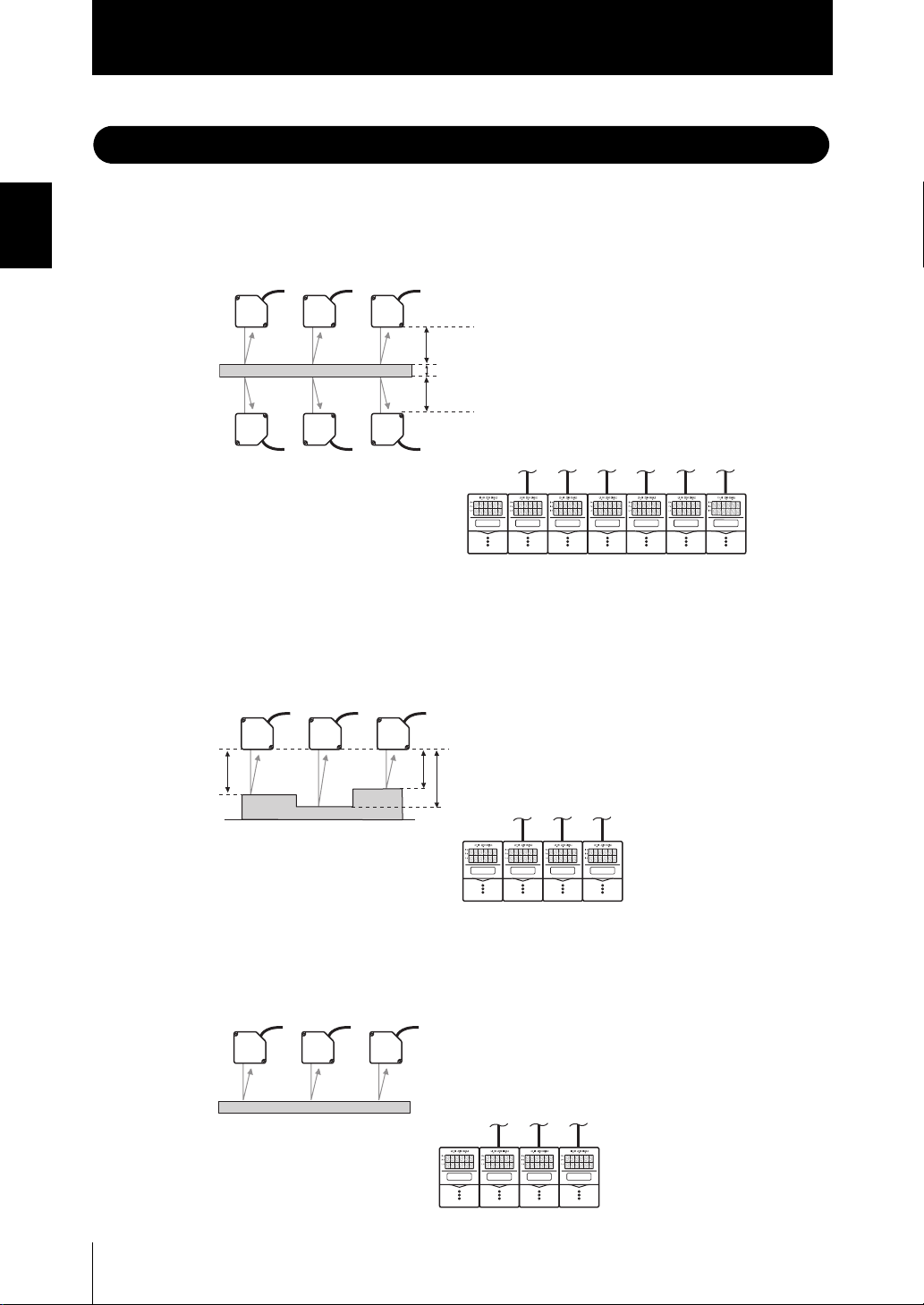
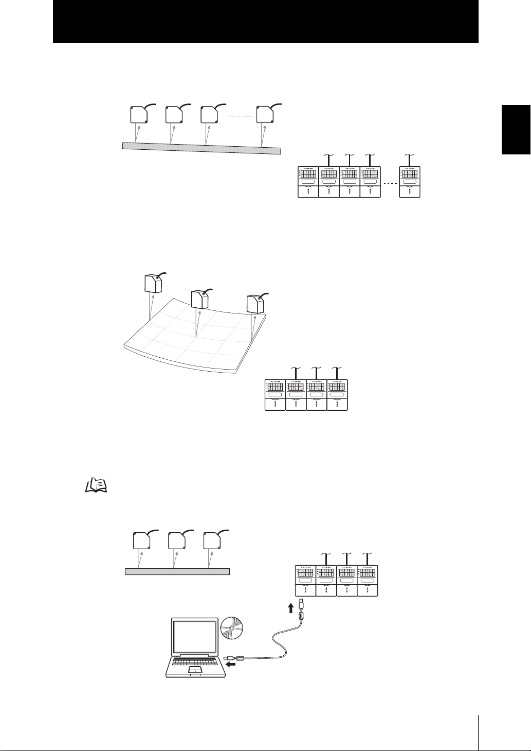
● Measurement of Workpiece Thickness at Multiple Locations
Sensor Heads can be placed so as to sandwich the workpiece and measure its thickness. Logic operations can be performed not only on one location but on multiple locations to calculate the difference in the measurement result.
● Measurement of Stepped Workpieces
Logic operations can be performed on measured values obtained from multiple Sensor
Controllers to measure steps in stepped workpieces.
1-4
● Measurement of Average Workpiece Height
Logic operations can be performed on measured values obtained from multiple Sensor
Controllers to measure the average height of workpieces.
ZS-MDC
User’s Manual
Section 1
S
o
(
y)
Multi-Controller Applications
● Measurement of Workpiece Flatness
Logic operations can be performed on measured values obtained from multiple Sensor
Controllers to measure the flatness of workpieces.
● Measurement of Workpiece Strain
Logic operations can be performed on measured values obtained from multiple Sensor
Controllers to measure the waviness, flexure, twist, and warp of steel plate and other
workpieces.
Section 1 FEATURES
● Batch-acquisition of Multi-point Measurement Data
Communications commands can be used to batch-acquire the measurement results of
gang-mounted Sensor Controllers.
About Digital Output p.3-17
You can also use the optional software “SmartMonitor Zero” to batch-display on the
digital displays and batch-log measurement results.
martMonitor Zer
sold separatel
ZS-MDC
User’s Manual
1-5
Section 1
Multi-Controller Applications
Section 1 FEATURES
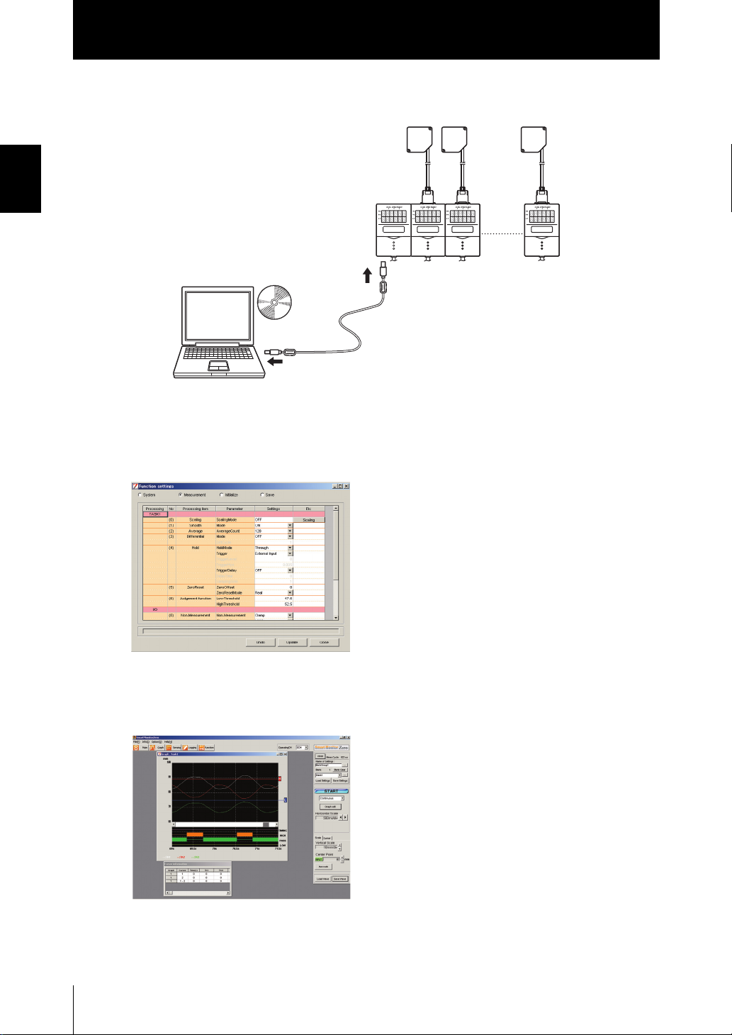
Moreover, connecting a personal computer pre-installed with SmartMonitor Zero to the
Multi-Controller allows you to perform the following.
● Gang-mounted Sensor Controllers can be set up.
The measurement conditions of each Sensor Controller can be set up, and settings
saved, read or copied.
1-6
* The screen shown here may differ from the actual screen.
● The state of gang-mounted Sensor Controllers can be monitored.
The operating state of each Sensor Controller can be batch-monitored. The waveforms
of each Sensor Controller can be displayed simultaneously.
* The screen shown here may differ from the actual screen.
ZS-MDC
User’s Manual
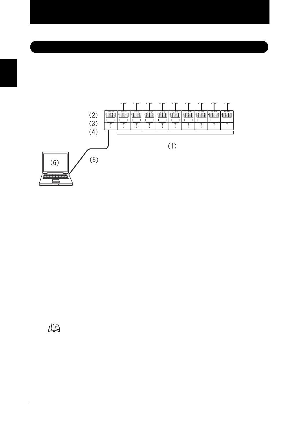
Basic Configuration
Section 1
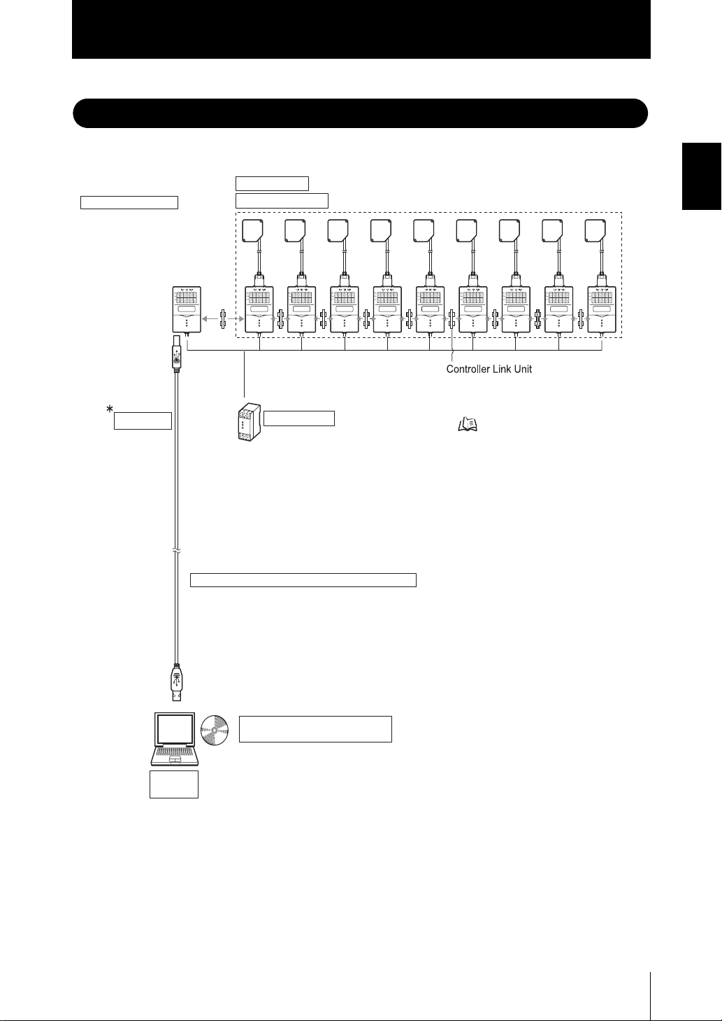
Basic Configuration
The figure below shows the Basic Configuration of the ZS Series.
This section detects the sensing object and processes measurement.
Up to 9 Sensor Controllers can be gang-mounted.
For details, refer to the User's Manual for the Sensor Controller.
ZS-XCN
This unit is for gang-mounting controllers.
+
-
Multi-Controller
ZS-MDC11/MDC41
The Multi-Controller calculates
the measurement information
of gang-mounted Sensor
Controllers, and outputs
the calculation results.
USB cable
(1m)
Sensor Heads
Sensor Controllers
Power Supply
DC24V ( 10%)
Recommended parts
(1) When 1 Sensor Controller is connected
S82K-01524 (DC24V, 0.6 A)
(2) When 2 to 3 Sensor Controllers are connected
S82K-05024 (DC24V, 2.1 A)
(3) When 4 to 10 Sensor Controllers are connected
Prepare the required number of (1) and (2)
power supplies above.
Section 1 FEATURES
p.2-5
RS-232C cable for personal computer connection
ZS-XRS2
This is used for communicating with a personal computer without a USB port.
(SmartMonitor Zero cannot be used on the RS-232C interface.
Communication using CompoWay/F or non-procedural protocol is possible.)
SmartMonitor Zero
(option software, sold separately)
ZS-SW11E
Personal
computer
allows you to operate the Multi-Controller and
connected Sensor Controller, monitor or log
measured values from a personal computer.
In this manual, the software is referred to as
"SmartMonitor Zero".
ZS-MDC
User’s Manual
1-7
Section 1
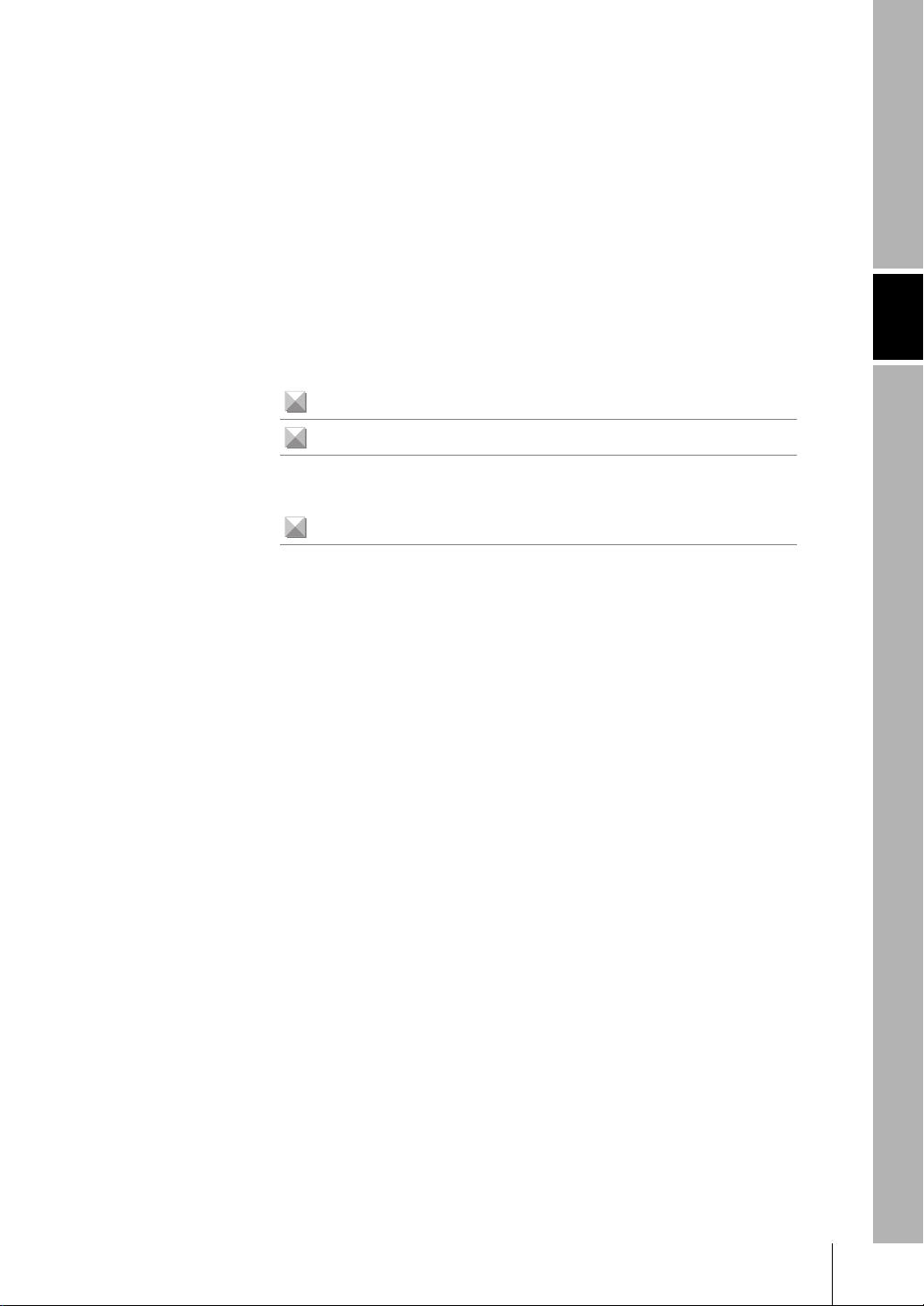
Part Names and Functions
Part Names and Functions
Section 1 FEATURES
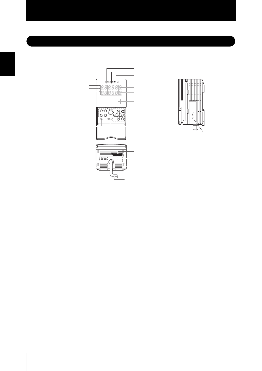
The following describes the names and functions of parts on the Multi-Controller.
(1) Laser indicator
(2) Zero Reset indicator
(3) ENABLE indicator
(12) HIGH indicator
(11) PASS indicator
(10) LOW indicator
(17) USB port
(4) Main display
(5) Sub-display
(6) LCD screen
(7) Control keys
(8) Mode switch(9) Threshold switch
(13) Coupler
(14) RS-232C connector
(15) Voltage/current switch
(16) I/O cable
(1) Laser indicator
Does not lit.
1-8
(2) Zero Reset indicator
The Zero Reset indicator lits when the zero reset function is enabled on the MultiController.
(3) ENABLE indicator
The ENABLE indicator lits when the Multi-Controller is ready for measurement. It
goes off when measurement is not possible (e.g. when the light amount received by
the sensor on the operation target CH is excessive or insufficient, when the
measuring range is exceeded, when the Sensor Head is not connected, or when
measurement is not being performed in the FUN mode).
(4) Main Display
The Main Display shows measured values after operations have been performed.
(5) Sub-display
The sub-display shows thresholds and additional information during measurement.
(6) LCD screen
RUN mode : Displays additional information for the main display and the setup
TEACH mode : Displays the menu for setting up the thresholds.
FUN mode : Displays the measurement condition setup menu.
ZS-MDC
User’s Manual
menu for display related information.

Section 1
Part Names and Functions
(7) Control keys
The Control Keys are for setting measurement conditions and other information. The
functions assigned to the Control Keys change according to the operating mode.
Displays and Key Operations p.3-5
(8) Mode Switch
The Mode Switch selects the operating mode.
RUN mode : Select this mode when performing regular measurement.
TEACH mode : Select this mode when setting the judgment thresholds.
FUN mode : Select this mode when setting measurement conditions.
(9) Threshold Selector Switch
The Threshold Selector switch selects whether to set (or display) the HIGH or LOW
threshold.
(10) LOW indicator
The LOW indicator lits when the condition “measured value < LOW threshold” is
satisfied.
(11) PASS indicator
The PASS indicator lits when the condition “LOW threshold ≤ measured value ≤
HIGH threshold” is satisfied.
Section 1 FEATURES
(12) HIGH indicator
The HIGH indicator lits when the condition “HIGH threshold < measured value” is
satisfied.
(13) Coupler
This connector is for connecting the Multi-Controller to the Sensor Controller.
(14) RS-232C connector
Connect the RS-232 cable when you are connecting the Multi-Controller to a
personal computer that does not have a USB port.
(15) Voltage/Current switch
The Voltage/Current switch selects between voltage output and current output.
Before operating this switch, make sure that the Multi-Controller is turned OFF. Also, make sure
that the load connected to “linear output wire (co-axial) — linear GND wire” satisfies the rating of
the set state (voltage or current output) before turning the Multi-Controller ON. Otherwise, the
Multi-Controller may be damaged.
Rating of connected load (I/O Circuit Diagrams) p.2-12
(16) I/O Cable
The I/O cable connects the Sensor Controller to the power supply and external
devices, such as timing sensors or programmable controllers.
(17) USB port
Connect the USB cable to the USB port to connect to a personal computer.
ZS-MDC
User’s Manual
1-9

Section 1
Part Names and Functions
Section 1 FEATURES
MEMO
1-10
ZS-MDC
User’s Manual
Section 2
INSTALLATION & CONNECTION
About Installation and Connection 2-2
Multi-Controller 2-3
Attaching the ferrite core 2-3
Installing the Multi-Controller 2-4
About the I/O cable 2-10
Section 2 INSTALLATION & CONNECTION
ZS-MDC
User’s Manual
2-1

Section 2
About Installation and Connection
About Installation and Connection
■ Checking the installation environment
Section 2 INSTALLATION & CONNECTION
■ Checking the installation site
■ About the power supply
Read “Precautions for Safe Use” at the beginning of this manual, and check the installation environment.
Read “Precautions for Correct Use” at the beginning of this manual, and check the
installation site.
Before installing and connecting the Multi-Controller, be sure to turn it OFF.
Also read “Precautions for Safe Use” and “Precautions for Correct Use” at the beginning of this manual, and check the power supply and wiring.
2-2
ZS-MDC
User’s Manual
Section 2
Multi-Controller
Multi-Controller
This section describes installation of the Multi-Controller and connection of the I/O cable.
Before connecting/disconnecting peripheral devices, make sure that the Multi-Controller is turned OFF.
The Multi-Controller may break down if the Multi-Controller is connected or disconnected while the
power is ON.
Attaching the ferrite core
Attach the ferrite core (provided with the Multi-Controller) to the I/O cable of the MultiController.
Section 2 INSTALLATION & CONNECTION
Ferrite core
ZS-MDC
User’s Manual
2-3
Section 2
Multi-Controller
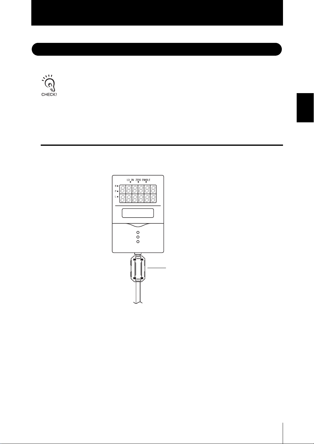
Installing the Multi-Controller
The Multi-Controller performs logical operations on the sensing information obtained from
multiple connected Sensor Controllers. Up to 9 Sensor Controllers can be gang-mounted.
For details on the Sensor Controller and Sensor Heads, refer to the User's Manual for the
Sensor Controller.
Section 2 INSTALLATION & CONNECTION
■ About channel No. when controllers are gang-mounted
Provide power to all connected Sensor Controllers.
When performing operation from SmartMonitor Zero or an external device, select the
controller to be set up by its channel No. The following shows how channel Nos. are
assigned when Sensor Controllers are gang-mounted.
2-4
Multi-Controller
CH0
ZS-MDC
User’s Manual
Sensor Controller
CH1
Sensor Controller
CH2
Sensor Controller
CH3
Sensor Controller
CH9
Section 2
Multi-Controller
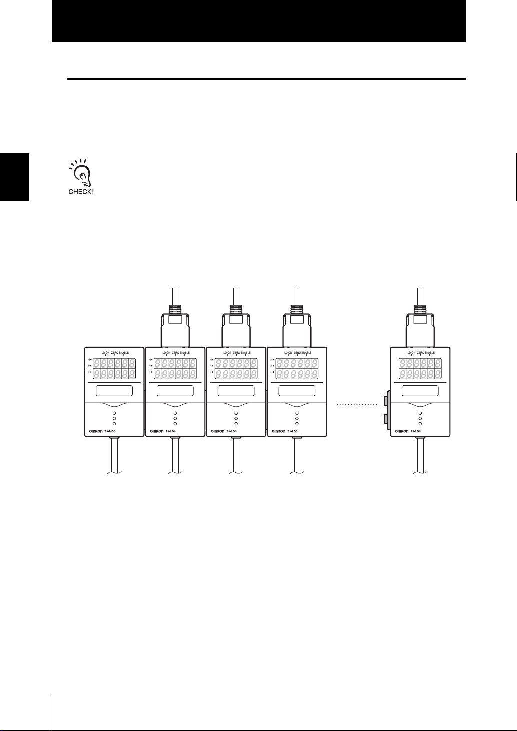
■ Installing on the DIN track
The following describes how to attach the 35 mm wide DIN track by quick, easy operation.
DIN track (sold separately)
PFP-100N (1 m)
PFP-50N (0.5 m)
PFP-100N2 (1 m)
End plate (sold separately)
PFP-M
● Installation procedure
The following describes how to install the Multi-Controller and Sensor Controller on the
DIN track.
1. Hook the connector end of the Sensor
Controller onto the DIN track.
Hook on connector
Hook on I/O cable
2. Push the Multi-Controller down onto the
DIN track until the hook on the I/O cable
side is locked.
Push down until you hear it snap into
place.
Section 2 INSTALLATION & CONNECTION
Always hook the connector end of the Multi-Controller on the DIN track first. Hooking the I/O cable
end on the DIN track first may impair the mounting strength of the DIN track attachment.
ZS-MDC
User’s Manual
2-5

Section 2
Multi-Controller
Section 2 INSTALLATION & CONNECTION
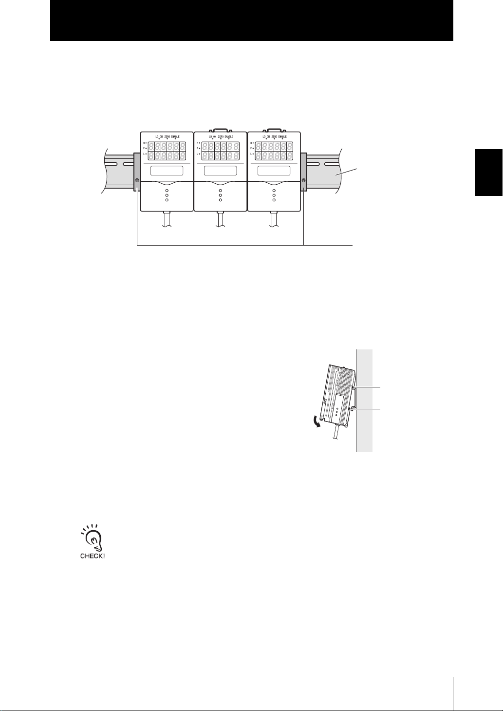
● Removal procedure
3. Open the connector cover on the con-
troller.
Slide the cover to remove.
H
H
LD
LD
ON
ON
ZE
ZE
P
P
R
R
O
O
ENABLE
ENABLE
L
L
Controller
Link Unit (sold
H
H
LD O
LD O
N
N
Z
Z
ERO
ERO
P
P
ENAB
ENAB
LE
LE
L
L
separately)
4. Insert the Controller Link Unit into the
connector on the Multi-Controller.
The connectors are designed to be connected in a
particular direction. Insert the connector in the direc-
tion so that the indented section of the Controller
Link Unit in the figure on the right matches the con-
nector protrusion on the Data Storage Unit.
Indented
section
5. Slide the Sensor Controller to insert to
the Controller Link Unit connector.
The following describes how to remove the Multi-Controller and Sensor Controller from
the DIN track.
1. Slide and remove the Sensor Controller
from the connector on the Controller
Link Unit.
2. Slide the Controller Link Unit and
remove from the connector on the MultiController.
3. Install the cover on the coupler of the controller.
Controller
H
H
L
L
D
D
O
O
N
N
Z
Z
E
E
P
P
R
R
O
O
ENA
ENA
B
B
LE
LE
L
L
Link Unit
(sold sepa-
rately)
H
H
L
L
D
D
O
O
N
N
Z
Z
E
E
P
P
R
R
O
O
ENA
ENA
BLE
BLE
L
L
2-6
ZS-MDC
User’s Manual

4. Pull the hook on the I/O cable end
downwards.
Section 2
Multi-Controller
5. Lift up the Sensor Controller from the I/O
cable end, and remove it from the DIN
track.
Hook on I/O cable
Section 2 INSTALLATION & CONNECTION
ZS-MDC
User’s Manual
2-7

Section 2
Multi-Controller
■ Mounting on a panel
The optional Panel Mount Adapters (ZS-XPM1/XPM2) can be used to mount the MultiController on a panel.
Panel Mount Adapters p.5-9
Section 2 INSTALLATION & CONNECTION
1. Install the Multi-Controller and Sensor Controller on the DIN track.
p.2-5
When mounting on a panel, be sure to install the DIN track on the rear side of the Multi-
Controller for support.
2. Push out the Multi-Controller and Sensor
Controller from the rear of the panel
towards the front.
H
H
L
L
D
D
O
O
N
N
Z
Z
E
E
P
P
R
R
O
O
ENA
ENA
B
B
LE
LE
L
L
H
H
L
L
D
D
O
O
N
N
Z
Z
E
E
P
P
R
R
O
O
ENA
ENA
B
B
LE
LE
L
L
Panel
H
H
L
L
D
D
O
O
N
N
Z
Z
E
E
P
P
R
R
O
O
ENA
ENA
B
B
L
L
L
L
E
E
3. Install the small Mount Adapters on the
four holes on the Multi-Controller and
Sensor Controller.
Install the small Mount Adapters on all gang-
mounted Multi-Controllers and Sensor
Controllers.
H
H
L
L
D
D
O
O
N
N
Z
Z
E
E
P
P
R
R
O
O
ENA
ENA
B
B
LE
LE
L
L
H
H
L
L
D
D
O
O
N
N
Z
Z
E
E
P
P
R
R
O
O
ENA
ENA
B
B
LE
LE
L
L
H
H
L
L
D
D
O
O
N
N
Z
Z
E
E
P
P
R
R
O
O
ENA
ENA
B
B
L
L
L
L
E
E
Panel
Mount
Adapter
2-8
ZS-MDC
User’s Manual
Panel Mount
Adapter

Section 2
Multi-Controller
4. Install the long Mount Adapters on the
two holes on the small Mount Adapter.
Install the long Mount Adapters only on both
sides of gang-mounted controllers.
5. Install the Multi-Controller and Sensor
Controller with Panel Mount Adapters
attached onto the panel from the front.
Take care not to pinch the I/O cable.
Panel Mount Adapter
H
H
L
L
D
D
O
O
N
N
Z
Z
E
E
P
P
R
R
O
O
ENA
ENA
B
B
LE
LE
L
L
H
H
L
L
D
D
O
O
N
N
Z
Z
E
E
P
P
R
R
O
O
ENA
ENA
B
B
LE
LE
L
L
H
H
L
L
D
D
O
O
N
N
Z
Z
E
E
P
P
R
R
O
OENA
ENA
B
B
L
L
L
L
E
E
Panel Mount Adapter
Panel
H
H
LD ON ZERO
LD ON ZERO
P
P
ENABLE
ENABLE
L
L
H
H
LD ON ZERO
LD ON ZERO
P
P
ENABLE
ENABLE
L
L
H
H
L
L
D ON
D ON
ZER
ZER
P
P
O
O
ENAB
ENAB
L
L
L
L
E
E
Section 2 INSTALLATION & CONNECTION
6. Hook the hooks of the mounting fixture
onto the two holes of the small Mount
Adapters and tighten the screws.
Attach two mounting fixtures each on all gang-
mounted Multi-Controllers and Sensor
Controllers.
7. Make sure that the Multi-Controller and
Sensor Controllers are firmly fixed on
the panel.
Mounting
fixture
ZS-MDC
User’s Manual
2-9

Section 2
About the I/O cable
About the I/O cable
■ Wiring the I/O cable
Section 2 INSTALLATION & CONNECTION
The following shows the leads that comprise the I/O cable.
Brown
Blue
Red
Green
Black
Pink
Gray
Co-axial (black)
Shielded
Yellow
Light blue
Purple
White
Orange
(1) Power supply
(2) GND
(3) OUT0
(4) OUT1
(5) OUT2
(6) OUT3
(7) OUT4
(8) Linear output
(9) Linear GND
(10) IN0
(11) IN1
(12) IN2
(13) IN3
(14) Unused
(1) Power supply
This connects the 24 VDC (±10%) power supply. When using a Multi-Controller with
a PNP output, the power supply terminal is also the common I/O terminal for all I/O
except for the linear output.Supply power from a DC power supply unit that has a
countermeasure (safety ultra-low voltage circuit) built-in for preventing high voltages
from occurring.
Recommended power supply unit p.1-7
Wire the power supply separately from other devices. Wiring them together or placing
them in the same duct may cause induction, resulting in malfunction or damage.
Supply power simultaneously to all gang-mounted controllers to be used.
When power is turned ON individually, the channels will not be recognized normally.
(2) GND
The GND terminal is the 0V power supply terminal. When using a Multi-Controller
with an NPN output, the GND terminal is also the common I/O terminal for all I/O
except for the linear output.
(3) OUT0 (HIGH output)
This outputs judgment results (HIGH).
2-10
(4) OUT1 (PASS output)
This outputs judgment results (PASS).
(5) OUT2 (LOW output)
This outputs judgment results (LOW).
ZS-MDC
User’s Manual

Section 2
About the I/O cable
(6) OUT3 (ENABLE output)
This turns ON when the Multi-Controller is ready for measurement. This output is
interlocked with the ENABLE indicator.
(7) OUT4 (BUSY output)
This turns ON during sampling with the hold function enabled. It allows you to check
whether or not the self-trigger is functioning correctly. It also turns ON during bank
switching.
(8) Linear output
The linear output outputs a current or voltage in accordance with the measured
value.
(9) Linear GND
The linear GND terminal is the 0V terminal for the linear output.
This ground wire must be grounded separately from the other ground wires.
Always ground the linear output terminal even when linear output is not used.
Section 2 INSTALLATION & CONNECTION
(10) to (13) IN0 to IN3
The following input signal assignments can be selected.
• Signal assignments
Signal
IN0 External trigger (timing) input Bank input A
IN1 Reset input Bank input B
IN2 Unused Unused
IN3 Zero reset input Zero reset input
Setting I/O Assignments p.3-16
When [Standard] is selected
(default)
When [Bank] is selected
• Signal functions
Signal Name Description
External trigger (timing) input This timing input is for signal input from external devices. Use it for hold
function timing.
Reset input This resets all executing measurements and outputs. While a reset is
being input, judgment output conforms to the non-measurement setting. If this reset input switches ON while the hold function is used, the
state in effect before the hold function was set will be restored.
Zero reset input This is used to execute and clear a zero reset.
Bank input A, B This is used for switching banks. Specify the bank No. in combinations
of A and B.
For details on the timing charts of external I/O, refer to User’s Manual for the Sensor Controller.
ZS-MDC
User’s Manual
2-11

Section 2
About the I/O cable
■ I/O Circuit Diagrams
●
NPN type (ZS-MDC11)
Brown
DC24V
Section 2 INSTALLATION & CONNECTION
Internal circuits
Current voltage/
output selector switch
40 Ω
Current output
4 to 20 mA
Voltage output
10 V
Red
OUT0
Green
OUT1
Black
OUT2
Pink
OUT3
Gray
OUT4
Blue
GND(0V)
Yellow
Light blue
Purple
White
Orange
Co-axial (black)
Shielded
IN0
IN1
IN2
IN3
Load
Linear output
Linear GND
Load
Load
Load
Load
Load
DC24V
Current output: 300Ω or less
Voltage output: 10 kΩ or more
2-12
ZS-MDC
User’s Manual

● PNP type (ZS-MDC41)
Internal circuits
Brown DC24V
Red
OUT0
Green
OUT1
Black
OUT2
Pink
OUT3
Gray
OUT4
Blue GND(0V)
IN0
Yellow
IN1
Light blue
IN2
Purple
IN3
White
Orange
Load
Load
Load
About the I/O cable
Load
Load
DC
24V
Section 2
Section 2 INSTALLATION & CONNECTION
Current voltage/
output selector switch
40Ω
Current output
4 to 20 mA
Voltage output
10 V
Co-axial (black)
Shielded
Linear output
Linear GND
Current output: 300 Ω or less
Load
Voltage output: 10 kΩ or more
ZS-MDC
User’s Manual
2-13

Section 2
About the I/O cable
MEMO
Section 2 INSTALLATION & CONNECTION
2-14
ZS-MDC
User’s Manual

Section 3
SETUP
Setting Flow 3-2
About Setup 3-4
Basic Knowledge for Operation 3-4
List of Setting Items 3-9
Selecting Tasks 3-13
Section 3 SETUP
Setting the Sensor Controller to Obtain Sensing Information from
Setting Assignments 3-14
Setting Logic Operation Methods 3-15
Setting I/O Assignments 3-16
Switching banks by external signal input 3-16
Changing Output Assignments 3-17
Changing Linear Output Assignments 3-17
About Digital Output 3-17
3-14
ZS-MDC
User’s Manual
3-1

Section 3
Setting Flow
Setting Flow
Section 3 SETUP
Installation and Connection
Gang-mount Sensor Controller to Multicontroller.
Preparation for Measurement
Power ON
Section 2
Installation & Connection
Setting the Sensor Controller to obtain sensing information from
Set the Sensor Controller to obtain sensing
information from and operations to be
performed.
Setting Filter Function
Set the filter conditions for processing
measured information.
Setting of Measurement Conditions
Setting output processing
Set how measured information is to be
processed for outputting the required values.
p.3-14
Sensor Controller User's Manual,
Section 3 Setup
p.3-16
Sensor Controller User's Manual,
Section 3 Setup
p.2-2
3-2
Setting the Threshold
Set the threshold value for judging measured
values.
External I/O
Set how measured values are to be output.
Output Results
Save Setup Data
Save the data you have set.
Save Setup
ZS-MDC
User’s Manual
Sensor Controller
User's Manual,
Section 3 Setup
Sensor Controller User's Manual,
Section 3 Setup
Sensor Controller User's Manual,
Section 3 Setup
After you have made or changed settings,
be sure to save the setup data. All settings
will be deleted if you turn the power OFF
without saving the data.

When a Problem Occurs...
Section 3
Setting Flow
The Multi-Controller does not operate correctly.
Troubleshooting
p.5-2
Want to know the meanings of terms
Glossary
p.5-5
Setting Banks
Set up the banks.
Set Up the System Environment
Set up the system environment.
Applied Use of Functions
An error message has appeared
When [Error] is Displayed on the
Main Display
Sensor Controller User's Manual,
Section 3 Setup
Sensor Controller User's Manual,
Section 3 Setup
p.5-3
Section 3 SETUP
Setting the Display Method
Set what is to be displayed on the MultiController during measurement in the RUN
mode.
Additional Functions
Sensor Controller User's Manual,
Section 3 Setup
ZS-MDC
User’s Manual
3-3

Section 3
About Setup
About Setup
The ZS-MDC Series can be set up on the Multi-Controller or on the SmartMonitor Zero
software utility.
This manual describes setup on the Multi-Controller.
For details on how to set up the ZS-L Series on SmartMonitor Zero, refer to Help
contained on the SmartMonitor Zero CD-ROM.
Section 3 SETUP
Basic Knowledge for Operation
The following describes basic operation of the Multi-Controller before you set up the ZS-L
Series.
■ Switching Modes
The ZS-MDC has the following 3 operating modes.Switch to the desired mode before
you start operation.
To switch the operating mode, use the Mode Switch.
TEACH
FUN RUN
3-4
Mode Description
FUN Mode Mode for setting the measurement conditions
RUN mode Normal operating mode
TEACH Mode This mode is for setting the judgment threshold values.
When you switch the operating mode after changing the measurement conditions, you will be
prompted to save the settings. Save the settings as required. If you turn off the Multi-Controller with-
out saving these settings, the newly set measurement conditions will be cleared from memory. You
can also save all the settings later on.
Sensor Controller User’s Manual, Section 3 Setup
ZS-MDC
User’s Manual

Section 3
About Setup
■ Displays and Key Operations
The Multi-Controller has digital displays and an LCD screen.The details displayed on
these differ according to the operating mode.
Main Display
Sub-display
LCD screen
Control keys
Alphabet characters that appear on the
digital displays
(1) FUN Mode
The LCD screen displays the setup menus.
The No. at the top of each menu corresponds to a function key.
“← →“ displayed at the top right of the LCD screen indicates that the setup menu is
made up of two or more pages. Scroll pages by the LEFT or RIGHT key.
Top menu in FUN mode
The currently selected bank No. will be displayed on
the main display (upper section).
The currently selected bank No. will be displayed on
the main display (lower section).
Section 3 SETUP
1SENSING
3OUTPUT
2FILTER
Pressing the MENU key in the FUN mode returns to
the display.
Key Operations
Key FUN Mode
Function keys Directly sets the No. preceding the items displayed on the LCD
screen.
LEFT key
←
→ RIGHT key
The function changes depending on the settings.
• Scrolls pages in list menus.
• Selects the digit of numerical values.
ZS-MDC
User’s Manual
3-5

Section 3 SETUP
Section 3
About Setup
Key FUN Mode
↑ UP key
↓ DOWN key
MENU key Displays the top menu of the FUN mode.
SET key Applies the item you are setting up.
ESC key Returns to the previous menu.
Changes numerical values during numerical value input.
The following example describes basic operations for changing the filter to [SMOOTH].
1. Press function key 2 representing
[FILTER].
2. Press function key 1 representing
[SMOOTH].
The currently selected No. is displayed
flashing.
3. Press function key 2 representing
[ON].
The “Complete!” message is displayed.
4. Press the MENU key to return to the
top menu.
Pressing the ESC key returns to the
previous menu.
1SENSING
3OUTPUT
1SMOOTH
3DIFF
1OFF
SMOOTH
Complete!
2FILTER
2AVERAGE
2ON
: ON
3-6
ZS-MDC
User’s Manual

Section 3
About Setup
● RUN Mode
In this mode, measured values are displayed on the main display, and threshold values
and other information are displayed on the sub-display.
Pressing the MENU key displays the display customize menu.
Measured value display
MAIN : MESURE
SUB : THRESH
MAIN : MESURE
SUB : DISTANCE
MAIN : MESURE
SUB : VOLTAGE
MAIN : MESURE
SUB : RESOLU
Display customise menu
1DIGITAL
3HELP
2LCD
Details displayed on the sub-display
Display Details Description
THRESH Displays the HIGH/LOW threshold values according to the setting of the
threshold switch.
VOLTAGE (CURRENT) Displays the voltage (current) to be linearized. The display details change
according to the setting of the current/voltage switch. (Values displayed here
are reference values only. These values differ from actual linear output values.)
RESOLU Displays the fluctuation width (peak to peak) of the measured value over a
fixed amount of time.
DISTANCE Displays the measured value before it is processed by hold or other functions.
Section 3 SETUP
Key Operations
Key Measured Value Display Display Customize Menu
Function keys Not used Directly select functions.
←
LEFT key
→ RIGHT key
Changes sub-display content. The function changes depend-
ing on the settings.
• Scrolls pages in list menus.
• Selects digits.
User’s Manual
ZS-MDC
3-7

Section 3
About Setup
Key Measured Value Display Display Customize Menu
↑ UP key
↓ DOWN key
MENU key Displays the display customize
SET key Executes a zero reset. Applies numerical value settings.
↑ UP key: Executes trigger input.
↓ DOWN key: Executes reset
input.
menu.
The function changes depending on the settings.
• Changes numerical values.
• Changes text.
Returns to the top of the display
customize menu.
Section 3 SETUP
ESC key Hold down for at least two sec-
onds to cancel a zero reset.
Returns to the previous menu.
When the top menu is displayed,
returns to the measured value
display.
● TEACH Mode
In this mode, the measured value is displayed at all times on the main display. The
threshold values are displayed on the sub-display. Which of the HIGH or LOW threshold
values is displayed changes according to the setting of the threshold selector switch.
TEACH MODE
MENU : TEACHING
Displayed alternately
Key Operations
Key TEACHING DIRECT IN
Function keys Not used Not used
TEACH MODE
: DIRECT IN
3-8
←
LEFT key
→ RIGHT key
↑ UP key
↓ DOWN key
MENU key Registers the measured value
SET key Not used Applies the newly set threshold
ESC key Not used Cancels the newly set threshold
ZS-MDC
User’s Manual
Not used Selects the digit in the threshold
numerical value.
Not used Changes the threshold numerical
value.
Not used
when this key is pressed as the
threshold value.
value.
value.

Section 3
About Setup
List of Setting Items
This manual describes only “FUN Mode-[SENSING]” functions unique to the Multi-Controller. Details of
other functions are the same as those for the Sensor Controller. Refer to the Sensor Controller Userís
Manual.
■ FUN Mode
This is the mode for setting the measurement conditions. The items that can be set differ according to which task is selected. When TASK1 is selected, all items including
items common to all tasks can be set. When a task other than TASK1 is selected, only
items specific to that task can be set.
● When TASK1 is selected
Section 3 SETUP
FUN Mode
SENSING SEL CH
CALC
FILTER SMOOTH
AVERAGE
DIFF
OUTPUT SCALING
HOLD TYPE
TRIGGER
DELAY
0RESET TYPE
OFFSET
Settings Default Value Option/Range
- Input A to input I p.3-14
CH OFF, CH (input A to input I), CALC
ON OFF, ON -
1 1, 2, 4, 8, 16, 32, 64, 128, 256, 512,
OFF OFF, ON -
OFF OFF, ON (AUTO, MAN) -
OFF
EXT
OFF OFF, ON (T-DELAY, T-TIME) -
REAL REAL, HOLD -
0 -999.99 to 999.999 -
(THICK, STEP, K+mX+nY, AVE,
MAX-MIN)
1024, 2048, 4096
OFF, PEAK, BOTTOM, P-P, AVERAGE,
SAMPLE
EXT, SELF-UP, SELF-DN
Pages
p.3-15
-
-
-
ZS-MDC
User’s Manual
3-9

Section 3
About Setup
Section 3 SETUP
Settings Default Value Option/Range
I/O SET NO-MEAS
JUDGE HYS
TIMER
ANALOG FOCUS
ADJUST
INPUT IN0
IN1
IN2
IN3
I/O SET
IN
OUT
ANALOG
DIGITAL
BANK CHANGE
CLEAR
CLAMP KEEP, CLAMP -
20 µm
OFF OFF, OFF DELAY (1 to 5000ms),
OFF OFF, ON -
OFF OFF, ON (-999 to 999) -
ON OFF, ON -
ON OFF, ON
ON OFF, ON
ON OFF, ON
TASK TASK (TASK1 to 4, ALL TASK,
TASK1 TASK1 to TASK4, NONE
TASK1 TASK1 to TASK4, NONE
- LOG1 to 9(NONE, INPUT A to
BANK1 BANK1, BANK2, BANK3, BANK4 -
- (Initializes bank settings.) -
0 to 999.999 -
ON DELAY (1 to 5000ms), ONE
SHOT (1 to 5000ms)
NONE), FUNC (NORMAL, BANK)
INPUT I, TASK1 to TASK4)
Pages
-
p.3-16
SYSTEM SAVE
INIT
INFO
CYCLE
VERSION
COM
(RS-232C)
LENGTH
PAR ITY
STOP
BAUDRAT
DELIMIT
COM MODE
NODE
KEYLOCK
ZERORST
LANGUAG
-
-
-
8BIT 8BIT, 7BIT -
NONE NONE, ODD, EVEN -
1BIT 1BIT, 2BIT -
38400 9600, 19200, 38400, 57600,
CR CR, LF, CR+LF -
COMPWAY COMPWAY, NORMAL -
0 0 to 16 -
OFF OFF, ON -
OFF OFF, ON -
Japanese Japanese, English -
(Saves Multi-Controller settings.)
(Initializes Multi-Controller settings.)
(Displays the current measurement
cycle.)
(Displays the Multi-Controller version.)
115200
-
-
-
-
-
3-10
ZS-MDC
User’s Manual

● When other than TASK1 is selected
Section 3
About Setup
FUN Mode
SENSING CALC
FILTER SMOOTH
AVERAGE
DIFF
OUTPUT SCALING
HOLD TYPE
TRIGGER
DELAY
0RESET TYPE
OFFSET
BANK
SYSTEM
(same as when
TASK1 is selected)
(same as when
TASK1 is selected)
Settings Default Value Option/Range
CH OFF, CH(input A to input I), CALC
ON OFF, ON -
1 1, 2, 4, 8, 16, 32, 64, 128, 256, 512,
OFF OFF, ON -
OFF OFF, ON (AUTO, MAN) -
OFF
EXT
OFF OFF, ON (T-DELAY, T-TIME) -
REAL REAL, HOLD -
0 -999.99 to 999.999 -
(THICK, STEP, K+mX+nY, AVE,
MAX-MIN)
1024, 2048, 4096
OFF, PEAK, BOTTOM, P-P, AVERAGE,
SAMPLE
EXT, SELF-UP, SELF-DN
Page
s
p.3-15
-
Section 3 SETUP
-
-
ZS-MDC
User’s Manual
3-11

Section 3
About Setup
■ RUN Mode
In the RUN mode, you can customize the details that are displayed in the digital displays.
To call the display customize menu, press the MENU key in the RUN mode.
Section 3 SETUP
RUN mode
DIGITAL DOT
LCD ON/OFF
Settings Default Value Option/Range
ECO
B.LIGHT
CUSTOM
HELP
■ TEACH Mode
This is the mode for setting the threshold values
TEACH Mode
Settings Default Value Option/Range
TEACHING
DIRECT IN
Page
s
3 0 to 5 -
NORMAL NORMAL, ECO, OFF -
ON ON, AUTOOFF, OFF -
ON ON, AUTOOFF, OFF -
U-OFF
D-OFF
-- -
-- -
--
U-ON/OFF, L-ON/OFF
Upper section customize, lower
section customize
-
Page
s
3-12
ZS-MDC
User’s Manual

Section 3
Selecting Tasks
Selecting Tasks
By assigning expressions to “tasks,” you can process (multi-tasking) multiple logic
operations (max. 4). After selecting the task in the task selection menu, make the various
settings for the selected task in the respective setup menus. The currently selected task is
displayed on the sub-display.
Press the ESC key with the FUN Mode-TOP menu displayed.
Setting Description
TASK1 Selects TASK1 as the destination to store the expression to.
TASK2 Selects TASK2 as the destination to store the expression to.
TASK3 Selects TASK3 as the destination to store the expression to.
TASK4 Selects TASK4 as the destination to store the expression to.
• In the RUN and TEACH modes, the task to display can be selected.As function keys correspond to
a stored task, press the function key of the task No. you want to display. (The currently selected task
is displayed as “TKX” on the LCD display.)
• The items that can be set in the FUN mode change according to the currently selected task.When
TASK1 is selected, all items including items common to all tasks can be set. When a task other than
TASK1 is selected, only items specific to that task can be set.Items common to all tasks are as fol-
lows:
• SEL CH
• NO-MEAS
• JUDGE
• ANALOG
• IN
• I/O SET
BANK and SYSTEM can also be changed whichever task is selected.
Section 3 SETUP
ZS-MDC
User’s Manual
3-13

Section 3
Setting the Sensor Controller to Obtain Sensing Information from
Setting the Sensor Controller to Obtain Sensing Information from
Set which gang-mounted Sensor Controller to obtain information from, and which logic
operations are to be performed on that information.
Setting Assignments
Assign the channel to perform logic operation on.
Section 3 SETUP
▲
FUNMode-[SENSING]-[SEL CH]
Setting Description
INPUT A (input A) Assigns the target Sensor Controller to input A.
Range: None, 1CH onwards (largest CH of gang-mounted Sensor Controllers)
(default: 1CH. Note that range becomes “None” if 1CH does not exist.)
INPUT B (input B) Assigns the target Sensor Controller to input B.
Range: None, 1CH onwards (largest CH of gang-mounted Sensor Controllers)
(default: 2CH. Note that range becomes “None” if 2CH does not exist.)
INPUT C (input C) Assigns the target Sensor Controller to input C.
Range: None, 1CH onwards (largest CH of gang-mounted Sensor Controllers)
(default: 3CH. Note that range becomes“None” if 3CH does not exist.)
INPUT D (input D) Assigns the target Sensor Controller to input D.
Range: None, 1CH onwards (largest CH of gang-mounted Sensor Controllers)
(default: 4CH. Note that range becomes “None” if 4CH does not exist.)
INPUT E (input E) Assigns the target Sensor Controller to input E.
Range: None, 1CH onwards (largest CH of gang-mounted Sensor Controllers)
(default: 5CH. Note that range becomes “None” if 5CH does not exist.)
INPUT F (input F) Assigns the target Sensor Controller to input F.
Range: None, 1CH onwards (largest CH of gang-mounted Sensor Controllers)
(default: 6CH. Note that range becomes “None” if 6CH does not exist.)
INPUT G (input G) Assigns the target Sensor Controller to input G.
Range: None, 1CH onwards (largest CH of gang-mounted Sensor Controllers)
(default: 7CH. Note that range becomes “None” if 7CH does not exist.)
INPUT H (input H) Assigns the target Sensor Controller to input H.
Range: None, 1CH onwards (largest CH of gang-mounted Sensor Controllers)
(default: 8CH. Note that range becomes “None” if 8CH does not exist.)
INPUT I (input I) Assigns the target Sensor Controller to input I.
Range: None, 1CH onwards (largest CH of gang-mounted Sensor Controllers)
(default: 9CH. Note that range becomes “None” if 9CH does not exist.)
3-14
ZS-MDC
User’s Manual

Section 3
Setting the Sensor Controller to Obtain Sensing Information from
Setting Logic Operation Methods
Set how logic operations are to be performed on the tasks and CH specified by the
assignment settings.
▲
FUNMODE-[SENSING]-[CALC]
Setting Description
OFF Expressions are not set.
CH Logic operations are not performed, and the measured value of a specific CH
is input as it is.Select the target CH.
CALC THICK
K-(X+Y)
Select this item to set the sandwiched thickness. (sandwiched measurement)
• Xrange: input A to input I, TASK1 to TASK4
• Yrange: input A to input I, TASK1 to TASK4
• The thickness input is automatically set.
During thickness input, the mode changes to the measurement
mode, and the current thickness value is displayed on the main dis-
play. For this reason, during thickness input enter in a measurement
ready state.
K
XY
Section 3 SETUP
STEP
X-Y
K+mX+nY Select this to perform logic operations on X and Y with the coefficient freely
AVE
(average height
measurement)
MAX-MIN
(flatness measurement)
Select this item to set step measurement. (step measurement)
• Xrange: input A to input I, TASK1 to TASK4
• Yrange: input A to input I, TASK1 to TASK4
Y
set.
• K range: -999999 to 999999
• m range: -10.0 to 10.0
• n range: -10.0 to 10.0
• Xrange: input A to input I, TASK1 to TASK4
• Yrange: input A to input I, TASK1 to TASK4
Select this item to average the values of input A to input I, and the values of
TASK1 to TASK4.
Set ON/OFF to each input and each TASK.The average of inputs set to ON
and TASK is calculated.
Select this item to subtract the maximum and minimum values by the values
of input A to input I.
Set ON/OFF to each input and each TASK.The average of inputs set to ON
and TASK is calculated.
X
Inputs do not undergo logical operation when “None” is set. Example: The operation “-B” is performed
when “None” is set to input A, “3CH” is assigned to input B and A-B is selected.
ZS-MDC
User’s Manual
3-15

Section 3
Setting I/O Assignments
Setting I/O Assignments
Switching banks by external signal input
Set the task or function to the external input.
If you use SmartMonitor Zero, you can change the function assignments of IN2 and IN3 if [BANK] is
selected. For details, refer to the Help for SmartMonitor Zero.
Section 3 SETUP
▲
FUN mode-[I/O SET]-[I/O SET]-[IN]
Setting Description
TASK Select to task for enabling the external signal lead. Note, however, that reset input
and bank inputs affects tasks at all times.
Range: TASK1 to TASK4, TASK-ALL
FUNC NORMAL Select this to use external input function as in standard applications so far (default
value).
IN0 IN1 IN2 IN3
External trigger
(timing) input
BANK Select this to switch banks using external inputs.
IN0 IN1 IN2 IN3
Bank input A Bank input B Unused Zero reset input
Reset input Unused Zero reset input
For bank inputs A and B, the bank can be selected in the following combinations.
Bank to be Selected Bank input A Bank input B
BANK1 OFF OFF
BANK2 OFF ON
BANK3 ON OFF
BANK4 ON ON
3-16
ZS-MDC
User’s Manual
• Bank switching is begun 0.5 seconds after the input state changes.
• At most it takes about 10 seconds to switch banks.
• During bank switching the BUSY output becomes ON.

Changing Output Assignments
▲▲ ▲
FUN mode-[I/O SET]-[I/O SET]-[OUT]
Setting Description
TASK1
TASK2
TASK3
TASK4
The measurement value of the task selected here is output as the judgment result
of the Multi-Controller.
Section 3
Setting I/O Assignments
Changing Linear Output Assignments
FUN Mode-[I/O SET]-[I/O SET]-[ANALOG]
Setting Description
TASK1
TASK2
TASK3
TASK4
The measurement value of the task selected here is linear-output from the MultiController.
About Digital Output
FUN Mode-[I/O SET]-[I/O SET]-[DIGITAL]-[LOG1 to 9]
Setting Description
NONE
Input A to input I
TASK1 to TASK4
Set this to batch-output multiple data to external devices using CompoWay/F or
non-procedural commands.
Assign to log 1 to 9 inputs A to I or TASK1 to 4 to be output. When a command is
input, the inputs or tasks are output continuously in order from log 1 to 9.
(The data of the nine channels can be batch-output when input A to I is set to log1
to 9 with all inputs assigned.)
For details on commands, refer to the “Communication Command Reference”
(provided separately).
When multi-channel waveforms are plotted or logging is performed on SmartMonitor Zero, the details set on SmartMonitor Zero are automatically reflected in this
setting.
Section 3 SETUP
ZS-MDC
User’s Manual
3-17

Section 3 SETUP
Section 3
Setting I/O Assignments
MEMO
3-18
ZS-MDC
User’s Manual

Section 4
APPLICATION SETTING EXAMPLES
Measuring the Thickness of Multiple Points (sandwiched thickness)
Measuring the Relative Difference between Steps 4-5
Measuring the Reference Difference between Steps 4-8
Measuring Flatness 4-10
Measuring the Average Height 4-12
Measuring the Twist of a Workpiece 4-14
Measuring the Warp of a Workpiece 4-17
4-2
Section 4 APPLICATION SETTING EXAMPLES
ZS-MDC
User’s Manual
4-1

Section 4
Measuring the Thickness of Multiple Points (sandwiched thickness)
Measuring the Thickness of Multiple Points (sandwiched thickness)
This is an example of how to measure the sandwiched thickness at three places on a
workpiece, and calculate the difference (max. value - min. value) of each measured
thickness value. [THICK] and [MAX-MIN] are used as the operation modes.
Input A Input C
Section 4 APPLICATION SETTING EXAMPLES
Input B Input D
For details on how to connect and install the Sensor Heads and Sensor Controllers, refer to the “ZS-L
User’s Manual”.
▲
FUN Mode-[SENSING]-[SEL CH]
Input E
Thickness
Input A Input B Input CInput D Input E Input F
Input F
CH0 CH1 CH2 CH3 CH4 CH5 CH6
The operation and/or measurement results are output
as judgement output or linear output.
4-2
1. Assign the CH No. of the controller to inputs
A to F to be used for the expression.
INPUT A:1CH
INPUT B:2CH
INPUT C:3CH
INPUT D:4CH
INPUT E:5CH
INPUT F:6CH
ZS-MDC
User’s Manual
1INPUT A
3INPUT C
2INPUT B

Measuring the Thickness of Multiple Points (sandwiched thickness)
▲
Press MENU key - ESC key.
2. Select [TASK1].
Section 4
▲
[SENSING]-[CALC]-[CALC]-[THICK]
3. Set the expression of TASK1.
INPUT X: INPUT A
INPUT Y: INPUT B
4. Place a workpiece of known thickness at the
rough sensor.
5. Select [THICK].
6. Enter the thickness of the workpiece.
The thickness of the workpiece you placed is
displayed on the LCD. Enter the thickness value
referring to the displayed value.
1TASK1
3TASK3
1INPUT X
3THICK
Input A
Input B
THICK : 0 1 0 . 0 0 0
DIG VAL
2TASK2
4TASK4
2INPUT Y
X
Y
SETOK
Section 4 APPLICATION SETTING EXAMPLES
7. Press the SET Key to apply the setting.
8. Following the same procedure as 2 to 7, set
up TASK2 and TASK3.
(TASK2) Enter C to input X and D to input Y.
(TASK3) Enter E to input X and F to input Y.
THICK : 0 1 0 . 0 0 0
Complete!
Input C
Input D
Input E
Input F
X
Y
ZS-MDC
User’s Manual
4-3

Section 4
Measuring the Thickness of Multiple Points (sandwiched thickness)
▲
Press MENU key - ESC key.
9. To set the expression for calculating the dif-
ference in the thickness of the 3 locations
for TASK4, select [TASK4].
▲
[SENSING]-[CALC]-[CALC]-[MAX-MIN]
10. Set task 1 to task3 for calculating the differ-
Section 4 APPLICATION SETTING EXAMPLES
ence to ON, and other tasks to OFF.
• To output the judgment result of the operation
▲
[I/OSET]-[I/O SET]-[OUT]
11. Select [TASK4] so that the judgment on the
thickness difference can be output.
• To linear-output the operation result
▲
[I/O SET]-[I/O SET]-[ANALOG]
11. Select [TASK4] so that the thickness differ-
ence can be linear-output.
1 TASK1
3 TASK3
1TASK1
3TASK3
1TASK1
3TASK3
1TASK1
3TASK3
2 TASK2
4TASK4
2TASK2
2TASK2
4TASK4
2TASK2
4TASK4
4-4
ZS-MDC
User’s Manual
The calculation results of each CH can be batch-acquired if you use the communication command.

Section 4
Measuring the Relative Difference between Steps
Measuring the Relative Difference between Steps
This is an example of how to measure the height at three locations on a workpiece, and
calculate the difference (step difference) between each of the measured values. Use
[STEP] (X-Y) for the expression.
Input A
Step difference
Step difference
For details on how to connect and install the Sensor Heads and Sensor Controllers, refer to the “ZS-L
User’s Manual.”
Input B Input C
The operation and/or measurement results are output
as judgement output or linear output.
Step difference
Input A Input B Input C
CH0 CH1 CH2 CH3
▲
FUN Mode-[SENSING]-[SEL CH]
1. Assign the CH No. of the controller to inputs
A to C to be used for the expression.
1INPUT A
3INPUT C
2INPUT B
Section 4 APPLICATION SETTING EXAMPLES
INPUT A:1CH
INPUT B:2CH
INPUT C:3CH
▲
Press MENU key - ESC key.
2. Select [TASK1].
1TASK1
3TASK3
2TASK2
4TASK4
ZS-MDC
User’s Manual
4-5

Section 4
Measuring the Relative Difference between Steps
▲
[SENSING]-[CALC]-[CALC]-[STEP]
3. Set the expression of TASK1.
INPUT X: INPUT A
INPUT Y: INPUT B
4. Following the same procedure as 2 to 3, set
up TASK2.
Section 4 APPLICATION SETTING EXAMPLES
INPUT X: INPUT B
INPUT Y: INPUT C
5. Following the same procedure as 2 to 3, set
up TASK3.
INPUT X: INPUT C
INPUT Y: INPUT A
1INPUT X 2INPUT Y
Input A Input B Input C
Y X
Input A Input B Input C
Input A
Y
Input B
Y
Input C
X
X
4-6
• To output the judgment result of the operation
▲
[I/O SET]-[I/O SET]-[OUT]
6. Select TASK1, TASK2, or TASK3 depending
on the details to be output.
To output judgment on the difference between
point A and point B: Set TASK1 to I/O SET
To output judgment on the difference between
point B and point C: Set TASK2 to I/O SET
To output judgment on the difference between
point C and point A: Set TASK3 to I/O SET
ZS-MDC
User’s Manual
1TASK1
3TASK3
2TASK2
4TASK4

Measuring the Relative Difference between Steps
• To linear-output the operation result
▲
[I/O SET]-[I/O SET]-[ANALOG]
Section 4
6. Select TASK1, TASK2, or TASK3 depending
on the details to be output.
1TASK1
3TASK3
2TASK2
4TASK4
To output judgment on the difference between
point A and point B: Set TASK1 to I/O SET
To output judgment on the difference between
point B and point C: Set TASK2 to I/O SET
To output judgment on the difference between
point C and point A: Set TASK3 to I/O SET
The calculation results of each CH can be batch-acquired if you use the communication command.
Section 4 APPLICATION SETTING EXAMPLES
ZS-MDC
User’s Manual
4-7

Section 4
Measuring the Reference Difference between Steps
Measuring the Reference Difference between Steps
This is an example of how to measure the height at three locations on a workpiece, and
calculate the difference (step difference) between the value of the reference height
(obtained by taking one of the locations to be the reference height) and the other two
locations. Use [STEP] (X-Y) for the expression.
Input A Input B Input C
Reference
difference
between steps
Section 4 APPLICATION SETTING EXAMPLES
For details on how to connect and install the Sensor Heads and Sensor Controllers, refer to the “ZS-L
User’s Manual.”
▲
FUN Mode-[SENSING]-[SEL CH]
1. Assign the CH No. of the controller to inputs
A to C to be used for the expression.
INPUT A:1CH
INPUT B:2CH
INPUT C:3CH
Reference
difference
between steps
The operation and/or measurement results are output
as judgement output or linear output.
Input A Input B Input C
CH0 CH1 CH2 CH3
1INPUT A
3INPUT C
2INPUT B
4-8
▲
Press MENU key - ESC key.
2. Select [TASK1].
ZS-MDC
User’s Manual
1TASK1
3TASK3
2TASK2
4TASK4

Measuring the Reference Difference between Steps
▲
[SENSING]-[CALC]-[CALC]-[STEP]
Section 4
3. Set the expression of TASK1.
INPUT X: INPUT A
INPUT Y: INPUT B
4. Following the same procedure as 2 to 3, set
up TASK2.
INPUT X: INPUT A
INPUT Y: INPUT C
• To output the judgment result of the operation
▲
[I/O SET]-[I/O SET]-[OUT]
5. Select TASK1 or TASK2 depending on the
details to be output.
1INPUT X 2INPUT Y
Input A Input B Input C
Y X
Input A Input B Input C
X
1TASK1
3TASK3
2TASK2
4TASK4
Y
Section 4 APPLICATION SETTING EXAMPLES
To output judgment on the difference between point A (reference point) and point
B: Set TASK1 to I/O SET
To output judgment on the difference between point A (reference point) and point
C: Set TASK2 to I/O SET
• To linear-output the operation result
▲
[I/OSET]-[I/O SET]-[ANALOG]
5. Select TASK1 or TASK2 depending on the
details to be output.
1TASK1
3TASK3
2TASK2
4TASK4
To output the difference between point A (reference point) and point B: Set TASK1
to I/O SET
To output the difference between point A (reference point) and point C: Set TASK2
to I/O SET
The calculation results of each CH can be batch-acquired if you use the communication command.
ZS-MDC
User’s Manual
4-9

Section 4
Measuring Flatness
Measuring Flatness
This is an example of how to measure the height at 9 locations on a workpiece, and
calculate the difference (max. value - min. value) between each measured point. [MAXMIN] is used as the operation mode.
Input A Input B Input C
Section 4 APPLICATION SETTING EXAMPLES
For details on how to connect and install the Sensor Heads and Sensor Controllers, refer to the “ZS-L
User’s Manual”.
▲
FUN Mode-[SENSING]-[SEL CH]
1. Assign the CH No. of the controller to inputs
A to I to be used for the expression.
Input I
Input A Input B Input C Input I
CH0 CH1 CH2 CH9CH3
The operation and/or measurement results are output
as judgement output or linear output.
1INPUT A
3INPUT C
2INPUT B
4-10
ZS-MDC
User’s Manual
INPUT A : 1CH
INPUT B : 2CH
INPUT C: 3CH
INPUT D: 4CH
INPUT E : 5CH
INPUT F : 6CH
INPUT G: 7CH
INPUT H: 8CH
INPUT I : 9CH

▲
Press MENU key - ESC key.
2. Select [TASK1].
Section 4
Measuring Flatness
▲
[SENSING]-[CALC]-[CALC]-[MAX-MIN]
3. Set input A to input I for calculating the
flatness to ON, and other input to OFF.
• To output the judgment result of the operation
▲
[I/O SET]-[I/O SET]-[OUT]
4. Select [TASK1] so that the judgment on the
flatness measurement can be output.
• To linear-output the operation result
▲
[I/O SET]-[I/O SET]-[ANALOG]
4. Select [TASK1] so that the flatness
measurement can be linear-output.
1TASK1
3TASK3
1INPUT A
3INPUT C
1TASK1
3TASK3
1TASK1
3TASK3
2TASK2
4TASK4
2INPUT B
Section 4 APPLICATION SETTING EXAMPLES
2TASK2
4TASK4
2TASK2
4TASK4
The calculation results of each CH can be batch-acquired if you use the communication command.
ZS-MDC
User’s Manual
4-11

Section 4
Measuring the Average Height
Measuring the Average Height
This is an example of how to measure the height at 3 locations on a workpiece, and
calculate the average of each measured height value. [AVERAGE] is used as the
operation mode.
Section 4 APPLICATION SETTING EXAMPLES
Input A Input B Input C
Input A Input B Input C
CH0 CH1 CH2 CH3
The operation and/or measurement results are output
as judgement output or linear output.
For details on how to connect and install the Sensor Heads and Sensor Controllers, refer to the “ZS-L
User’s Manual”.
▲
FUN Mode-[SENSING]-[SEL CH]
1. Assign the CH No. of the controller to inputs
A to C to be used for the expression.
1INPUT A
3INPUT C
2INPUT B
INPUT A:1CH
INPUT B:2CH
INPUT C:3CH
▲
Press MENU key - ESC key.
2. Select [TASK1].
4-12
ZS-MDC
User’s Manual
1TASK1
3TASK3
2TASK2
4TASK4

▲
[SENSING]-[CALC]-[CALC]-[AVE]
Section 4
Measuring the Average Height
3. Set input A to input C for calculating the
average to ON, and other inputs to OFF.
• To output the judgment result of the operation
▲
1INPUT A
3INPUT C
2INPUT B
[I/O SET]-[I/O SET]-[OUT]
4. Select [TASK1] so that the judgment on the
average value can be output.
• To linear-output the operation result
▲
1TASK1
3TASK3
2TASK2
4TASK4
[I/O SET]-[I/O SET]-[ANALOG]
4. Select [TASK1] so that the average value can
be linear-output.
The calculation results of each CH can be batch-acquired if you use the communication command.
1TASK1
3TASK3
2TASK2
4TASK4
Section 4 APPLICATION SETTING EXAMPLES
ZS-MDC
User’s Manual
4-13

Section 4
Measuring the Twist of a Workpiece
Measuring the Twist of a Workpiece
This is an example of how to measure the height at 4 locations on a workpiece, and
calculate the difference (twist) between each of the measured values. Use [X-Y] for the
expression.
Input B
Section 4 APPLICATION SETTING EXAMPLES
For details on how to connect and install the Sensor Heads and Sensor Controllers, refer to the “ZS-L
User’s Manual”.
▲
FUN Mode-[SENSING]-[SEL CH]
Input A
The operation and/or measurement results are output
as judgement output or linear output.
Input D
Input C
Input A Input B Input C
CH0 CH1 CH2 CH3 CH4
Input D
4-14
1. Assign the CH No. of the controller to inputs
A to C to be used for the expression.
INPUT A:1CH
INPUT B:2CH
INPUT C:3CH
ZS-MDC
User’s Manual
1INPUT A
3INPUT C
2INPUT B

▲
Press MENU key - ESC key.
2. Select [TASK1].
Section 4
Measuring the Twist of a Workpiece
▲
[SENSING]-[CALC]-[CALC]-[STEP]
3. Set the expression of TASK1.
INPUT X: INPUT A
INPUT Y: INPUT B
4. Following the same procedure as 2 to 3, set
up TASK2.
INPUT X: INPUT D
INPUT Y: INPUT C
1TASK1
3TASK3
1INPUT X 2INPUT Y
Input B
Input B
2TASK2
4TASK4
Input A
Input C
Input A
Input C
Input D
Input D
Section 4 APPLICATION SETTING EXAMPLES
5. Following the same procedure as 2 to 3, set
up TASK2.
INPUT X: TASK 1
INPUT Y: TASK 2
Input B
Input A
Input D
Input C
ZS-MDC
User’s Manual
4-15

Section 4
Measuring the Twist of a Workpiece
• To output the judgment result of the operation
▲
[I/O SET]-[I/O SET]-[OUT]
6. Select [TASK3] so that the judgment on the
twist can be output.
• To linear-output the operation result
▲
[I/O SET]-[I/O SET]-[ANALOG]
6. Select [TASK3] so that the twist value can be
linear-output.
Section 4 APPLICATION SETTING EXAMPLES
The calculation results of each CH can be batch-acquired if you use the communication command.
1TASK1
3TASK3
1TASK1
3TASK3
2TASK2
4TASK4
2TASK2
4TASK4
4-16
ZS-MDC
User’s Manual

Section 4
Measuring the Warp of a Workpiece
Measuring the Warp of a Workpiece
In the example below, the difference between the points on both edges (input A point and
input C point) of the workpiece, the average distance value, and the measured value (input
B point) of the center is taken to be the warp amount. Expression: Z=B- (A+C)/2. In the
actual setting, calculation mode “K+mX+nY” is used.
Input A
Input B
Input C
Input A Input B Input C
Section 4 APPLICATION SETTING EXAMPLES
CH0 CH1 CH2 CH3
The operation and/or measurement results are output
as judgement output or linear output.
For details on how to connect and install the Sensor Heads and Sensor Controllers, refer to the “ZS-L
User’s Manual”.
▲
FUN Mode-[SENSING]-[SEL CH]
1. Assign the CH No. of the controller to inputs
A to C to be used for the expression.
1INPUT A
3INPUT C
2INPUT B
INPUT A:1CH
INPUT B:2CH
INPUT C:3CH
ZS-MDC
User’s Manual
4-17

Section 4
Measuring the Warp of a Workpiece
▲
Press MENU key - ESC key.
2. Select [TASK1].
▲
[SENSING]-[CALC]-[CALC]-[K+mX+nY]
3. Set the expression of TASK1.
Section 4 APPLICATION SETTING EXAMPLES
INPUT K:0
INPUT m:1
INPUT n:1
INPUT X: INPUT A
INPUT Y: INPUT C
4. Following the same procedure as 2 to 3, set
up TASK2.
INPUT K:0
INPUT m:1
INPUT n:-0.5
INPUT X: INPUT B
INPUT Y:TASK1
1TASK1
3TASK3
1INPUT A
3INPUT C
Input A
Input A
2TASK2
4TASK4
2INPUT B
Input B
Input B
Input C
Input C
4-18
ZS-MDC
User’s Manual

• To output the judgment result of the operation
▲
[I/O SET]-[I/O SET]-[OUT]
Section 4
Measuring the Warp of a Workpiece
5. Select [TASK2] so that the judgment on the
warp can be output.
• To linear-output the operation result
▲
1TASK1
3TASK3
2TASK2
4TASK4
[I/O SET]-[I/O SET]-[ANALOG]
5. Select [TASK2] so that the warp value can be
linear-output.
The calculation results of each CH can be batch-acquired if you use the communication command.
1TASK1
3TASK3
2TASK2
4TASK4
Section 4 APPLICATION SETTING EXAMPLES
ZS-MDC
User’s Manual
4-19

Section 4
Measuring the Warp of a Workpiece
MEMO
Section 4 APPLICATION SETTING EXAMPLES
4-20
ZS-MDC
User’s Manual

Section 5
APPENDIX
Troubleshooting 5-2
Error Messages and Countermeasures 5-3
Q&A 5-4
Glossary 5-5
Specifications and External Dimensions 5-6
Version Up Information 5-12
Index 5-13
Revision History 5-16
Section 5 APPENDIX
ZS-MDC
User’s Manual
5-1

Section 5
Troubleshooting
Section 5 APPENDIX
Troubleshooting
This section describes countermeasures for temporary hardware problems. Check the
malfunction in this section before sending the hardware for repair.
Problem Probable cause and possible countermeasure Pages
Device restarts during operation. • Is the power supply device connected correctly? p.2-10
Judgments are not output to
external device.
No input signal received • Are all cables connected correctly?
No communications with personal computer
Strange linear output levels • Is the voltage/current switch on the bottom of the Sensor Controller
The main display remains on
[-----].
The measured values fluctuate
and are not stable depending on
day and time.
• Are all cables connected correctly?
• Is the signal line disconnected?
• Are reset inputs short-circuited?
• Is the signal line disconnected?
• Is the USB cable connected correctly?
• Is the RS-232 cable connected correctly?
set to the correct position?
• Has the correct selection (voltage/current) been made in the focus
settings? Linear output levels can be fine-tuned.
• Has a timing input been made while the hold function is enabled
and the trigger type has been set to [EXT]?
• If the hold function is enabled and the trigger type is [SELF-UP] or
[SELF-DOWN], has the self-trigger level been set to an appropriate value?
• This problem may be due to temperature characteristics. Execute
zero reset periodically using the standard object to correct this
problem.
p.2-10
p.2-10
—
p.1-8
—
—
—
5-2
ZS-MDC
User’s Manual

Section 5
Error Messages and Countermeasures
Error Messages and Countermeasures
■ When [Error] Is Displayed on the Main Display
Display Details Cause Countermeasure
LCD screen
(upper section)
■ When all digits on the main display and sub-display blink
Overcurrent One or all of the judgment out-
puts are short-circuited.
Calculation data error One (or all) of the channels
assigned to the operation input
cannot be measured.
Cancel the load short-circuit.
(Recovery is automatic after the
load short-circuit is canceled.)
Check the measurement state of
the channels assigned to the operation input, and set all channels to
a measurable state.
Display Details Cause Countermeasure
LCD screen SYSTEM ERROR
CONNECT
SYSTEM ERROR
BANK DATA
SYSTEM ERROR
MAIN COM
The controller is not connected. Connect the Controller.
Bank data in the Sensor Controller in error
Internal error Turn the sensor ON again.
■ Others
Display Details Cause Countermeasure
LCD upper section
Main Display – – – – – – • The sensor is standing by
Disp range error The measurement result
exceeds the number of displayed digits.
for measurement.
• No channels are assigned
to inputs. (Assignments
are set to “NONE”.)
Section 5 APPENDIX
Hold the UP key down for 3 seconds, and then hold the DOWN
key down for 3 seconds.
The sensor is turned ON again
and restored after the device is
initialized.
Change the decimal point digit
setting.
• When hold is set, start sampling and apply the hold
value.
• Assign the channels.
ZS-MDC
User’s Manual
5-3

Section 5
Q&A
Section 5 APPENDIX
Q&A
Question Answer
When scaling is executed, an error appears and
settings cannot be made.
When focusing is executed, an error appears and
settings cannot be made.
Scaling cannot be set for one of the following reasons:
• Scaling has been attempted when the measured value is
outside the measuring range.
• When two-point scaling has been executed, the distance
between the measured values for the two points is not 1%
or more of the rated measuring range.
Monitor focus settings cannot be made when the distance
between the two specified points is not 1% or more of the
rated measuring range.
5-4
ZS-MDC
User’s Manual

Section 5
Glossary
Glossary
Te rm Explanation
Measured value The measured value is the operation result displayed on the main display of the Multi-Con-
troller in the RUN and TEACH modes. It is the value when each of the currently set functions (e.g. hold) has been processed.
p.3-7
Present value The present value is the current measurement result for the target Multi-Controller.
It is the value before each of the currently set functions (e.g. hold) has been processed.
Press the LEFT or RIGHT Key in the RUN mode to display the present value on the subdisplay.
p.3-7
Judgment output “Judgment output” is a general term for the HIGH, PASS, and LOW outputs. Judgment out-
puts are made in the RUN or TEACH mode based on the display values and the threshold,
hysteresis width, and timer settings.
SmartMonitor Zero This is software that runs on a personal computer.
This software enables communication with ZS-MDC, sets the measurement conditions of
the Multi-Controller and gang-mounted Sensor Controllers, saves setting data, and displays measurement results as a graph.
Section 5 APPENDIX
ZS-MDC
User’s Manual
5-5

Section 5
0
0
90
90
3
Specifications and External Dimensions
Section 5 APPENDIX
Specifications and External Dimensions
Multi-Controller
ZS-MDC11/MDC41
(Unit: mm)
52.50 60
.
131
24.2
ZS-MDC
5-6
User’s Manual
.
2.
10.80

Section 5
Specifications and External Dimensions
Item ZS-MDC11 ZS-MDC41
I/O type NPNtype PNPtype
No. of samples to average 1, 2, 4, 8, 16, 32, 64, 128, 256, 512, 1024, 2048, or 4096
Number of mounted Sensor Heads Cannot be connected
Connectable version of Sensor Controller Ver2.0 or later
Number of mounted Sensor Controllers Max. 9
(The Controller Link Unit is needed for gang-mounting.)
Exte
Connection method Serial I/O or connector
rnal
I/F
Serial I/O USB2.0 1 port, FULL SPEED [12 Mbps], MINI-B
RS-232C 1 port, max. 115200 bps
Output Judgment output
3 outputs: HIGH/
PASS/LOW
Linear output Selectable from voltage/current
Input ZERO reset input
ZERO reset execution/cancel
Timing input
Sample cycle specified when hold function is enabled
RESET input
Reset of hold state
Status indicators HIGH (orange), PASS (green), LOW (orange),
Segment display Main display 8-segment red display, 6 digits
Sub-display 8-segment green display, 6 digits
LCD 16 digits x 2 rows, color of characters: green, resolution per charac-
Setting input Setting keys Direction keys (UP/DOWN/LEFT/RIGHT), SET key, ESC key,
Slide switch Threshold switch (H/L 2-state)
Power supply voltage 21.6 V to 26.4 V (including ripple)
Current consumption 0.5 A max.
Insulation resistance Across all lead wires and controller case: 20 M (by 250 V megger)
Dialectic strength Across all lead wires and controller case, 1000 VAC, 50/60 Hz, 1
Noise immunity 1500 V peak-to-peak, pulse width 0.1 µs/1 µs, rising edge: 1 ns
Vibration resistance (destructive) 10 to 150 Hz, 0.7-mm double amplitude, 80 min each in X, Y, and Z
Prewired (standard cable length: 2 m)
NPN open-collector, 30 VDC, 50 mA
max. residual voltage; 1.2 V max.
(selected by slide switch on base)
• At voltage output: -10 to +10 V, output impedance: 40
• At current output: 4 to 20 mA, max. load resistance: 300
ON: Short-circuited with 0V terminal
or 1.5 V max.
OFF: Open (leakage current: 0.1 mA
max.)
LDON (green), ZERO (green), ENABLE (green)
ter: 5 x 8 pixel matrix
MENU key, function keys (1 to 4)
MODE switch (FUN/TEACH/RUN 3-state)
min
pulse
directions
PNPopen-collector 50 mA
max. residual voltage;1.2V
max.
ON: Supply voltage short-circuited or within supply voltage -1.5 V
OFF: Open (leakage current:
0.1 mA max.)
Section 5 APPENDIX
ZS-MDC
User’s Manual
5-7

Section 5
Specifications and External Dimensions
Section 5 APPENDIX
Item ZS-MDC11 ZS-MDC41
Shock resistance (destructive) 300 m/s2 3 times each in six directions (up/down, left/right, forward/
backward)
Ambient temperature Operating: 0 to 50°C
Storage: -15 to +60°C (with no icing or condensation)
Ambient humidity Operating and storage: 35% to 85% RH (with no condensation)
Materials Case: Polycarbonate (PC)
Weight Approx. 280 g (excluding packing materials and accessories)
5-8
ZS-MDC
User’s Manual

Panel Mount Adapters
)
(60 n)+12
60 n
3
3
l
.
ZS-XPM1/XPM2
When mounting on a panel
Section 5
Specifications and External Dimensions
(Unit: mm)
DIN track
0
Panel
1
(140)
Panel cutout dimensions
Panel cutout dimensions
n: number of gang-mounted controllers (1 to 10)
Item ZS-XPM1 (for 1st unit) ZS-XPM2 (for 2nd unit onwards)
Appearance
(60 n)+8
Panel Mount
Adapter
Note 1: Dimensions are shown for a pane
thickness of 2.0 mm
Panel
Note 1
Section 5 APPENDIX
116 1
Applicable controller ZS Series
Vibration resistance 10 to 150 Hz, 0.7-mm double amplitude, 80 min each in X, Y, and Z directions
Shock resistance 300 m/s
Materials Polycarbonate (PC), etc.
Weight Approx. 50g
2
3 times each in six directions (up/down, left/right, forward/backward)
ZS-MDC
User’s Manual
5-9

Section 5
.
70
e
/insulator diameter: 0.38)
)
r
pq
r
0
0
Specifications and External Dimensions
RS-232C Cable for Connecting to a Personal Computer
ZS-XRS2
(Unit: mm)
2.2
.2
Section 5 APPENDIX
.
10 1
Signal Name Pin No.
NC
SD(TXD)
RD(RXD)
RS(RTS)
CS(CTS)
NC
NC
NC
SG(GND)
NC
10-pin square connecto
Fitting
1
2
3
4
5
6
7
8
9
10
9-pin square connecto
PVC insulated round cable 3.89 mm dia. cor
Note 1: Connector is socket type
67 89
Signal NamePin No.
1NC
2 RD(RXD)
3 SD(TXD)
4NC
5SG(GND)
6NC
7 RS(RTS)
8 CS(CTS)
9NC
Applicable controller ZS Series
Ambient temperature Operating: 0 to 50°C, Storage: -15 to +60°C (with no icing or condensation)
Ambient humidity Operating and storage: 35% to 85% RH (with no condensation)
Dialectic strength 1,000 VAC, 50/60 Hz for 1 min
Insulation resistance 100 M (by 500 VDC megger)
Vibration resistance 10 to 150 Hz, 0.7 mm double amplitude, 80 min each in X, Y, and Z directions
Shock resistance 300 m/s
Materials Cable sheath: PVC
Weight Approx. 50 g
ZS-MDC
5-10
User’s Manual
Item ZS-XRS2
2
3 times each in six directions (up/down, left/right, forward/backward)

Controller Link Unit
60
50
8
0
50
ZS-XCN
Section 5
Specifications and External Dimensions
1
1.
.4
.
(Unit: mm)
Section 5 APPENDIX
4.
Item ZS-XCN
Applicable controller ZS Series
Ambient temperature Operating: 0 to 50°C, Storage: -15 to +60°C (with no icing or condensation)
Ambient humidity Operating and storage: 35% to 85% RH (with no condensation)
Vibration resistance 10 to 150 Hz, 0.7 mm double amplitude, 80 min each in X, Y, and Z directions
Shock resistance 300 m/s
Materials Polycarbonate (PC), etc.
Weight Approx. 10g
2
3 times each in six directions (up/down, left/right, forward/backward)
ZS-MDC
User’s Manual
5-11

Section 5
Version Up Information
Version Up Information
This section describes the revisions made to the software.
■ Ver1.00 to Ver1.50
Description of Change Pages
Task setup function was added. p.3-13
Logic operation can be performed on the information of Sensor Controllers up to nine channels. p.3-14
“K+mX+nY” that enables average height measurement and flexible formulas on types of logic
operations were added.
The zero reset memory function was added. *
The input signal setup function was added. *
The I/O assignment function was added. p.3-16
*Refer to the User’s Manual for the Sensor Controller.
p.3-15
Section 5 APPENDIX
■ Ver1.50 to Ver2.00
Description of Change Pages
RS-232C “delimiter”, and “CompoWay/F”, “Non-procedural” and “Node” were added to the
communication specifications.
The Data Storage unit (ZS-DSU) was supported. —
SmartMonitor Zero was supported. —
*Refer to the Userís Manual for the Sensor Controller.
*
5-12
ZS-MDC
User’s Manual

Index
Section 5
Index
A
ANALOG 3-17
average height measurement
CALC
3-15
B
Bank switching 3-16
Basic Configuration
BUSY output
1-7
2-11
C
CALC 3-15
Control keys
Controller Link Unit
Coupler
3-5
Connection
Specifications and
Dimensions
2-5
5-11
1-9
D
DIGITAL 3-17
E
ENABLE
indicator
Output
Extension Cable
1-8
2-11
5-11
F
Ferrite core
Multi-Controller
flatness measurement
CALC
3-15
FUN Mode
3-5
2-3
H
HIGH
indicator
Output
1-9
2-10
I
I/O cable 2-10
I/O circuit diagrams
I/O SET
INPUT
3-16, 3-17
3-14
2-13
K
K+mX+nY
CALC
3-15
L
Laser indicator 1-8
LCD screen
name
3-5
LD ON
LOG
LOW
1-8
3-17
indicator
Output
1-9
2-10
M
Main Display 3-5
Mode Switch
Multi-Controller
3-4
Attaching the ferrite core
Installation
Part Names
Specifications and
Dimensions
2-4
1-8
5-6
O
OUT 3-17
OUT0 to 4
Output cable
2-10
2-10
P
PASS
indicator
Output
Power supply
1-9
2-10
1-7
R
RS-232C
cable external
dimensions
Connector
RUN mode
3-7
5-10
1-9
S
SEL CH 3-14
SENSING
STEP
Sub-display
3-14
CALC
3-15
3-5
T
TASK 3-13
TEACH Mode
THICK
CALC
Threshold Selector Switch
3-8
3-15
1-9
2-3
Section 5
APPENDIX
ZS-MDC
User’s Manual
5-13

Section 5
Index
U
USB
port
1-9
V
Voltage/Current switch 1-9
W
wiring 2-10
Z
Zero reset
indicator
1-8
Section 5
APPENDIX
5-14
ZS-MDC
User’s Manual

MEMO
Section 5
Index
Section 5
APPENDIX
ZS-MDC
User’s Manual
5-15

Revision History
Revision History
A manual revision code appears as a suffix to the catalog number at the bottom of the front
and back covers of this manual.
Section 5 APPENDIX
Cat. No.
Revision code Date Revised contents
01 October 2004 Original production
Z209-E2-01
Revision code
5-16
ZS-MDC
User’s Manual
 Loading...