

Omron ZS-L User Manual

USER’S MANUAL
Smart Sensor
ZS-L Series (Ver 2.0)
Cat. No. Z208-E1-02

Introduction
Introduction
This manual provides information regarding functions, performance and operating
This manual provides information regarding functions, performance and operating
methods that are required for using the ZS-L Series.
methods that are required for using the ZS-L Series.
When using the ZS-L Smart Sensor, be sure to observe the following:
When using the ZS-L Smart Sensor, be sure to observe the following:
• The ZS-L Smart Sensor must be operated by personnel knowledgeable in electrical engi-
• The ZS-L Smart Sensor must be operated by personnel knowledgeable in electrical engineering.
neering.
• To ensure correct use, please read this manual thoroughly to deepen your understanding
• To ensure correct use, please read this manual thoroughly to deepen your understanding
of the product.
of the product.
• Please keep this manual in a safe place so that it can be referred to whenever necessary.
• Please keep this manual in a safe place so that it can be referred to whenever necessary.
How to Switch the Display Language to English
How to Switch the Display Language to English
Turn the power ON with the MENU key held down. This displays the display language
Turn the power ON with the MENU key held down. This displays the display language
selection screen.
selection screen.
Select Language
1
If you change and save the setting, the Controller will start up with messages displayed in
If you change and save the setting, the Controller will start up with messages displayed in
English when it is next started up.
English when it is next started up.
2Japanese English
Introduction
INTRODUCTION
SECTION 1
SECTION 2
SECTION 3
SECTION 4
SECTION 5
APPLICATION CONSIDERATIONS (Please Read)
Section 1 Section 2 Section 3 Section 4 Section 5 Section 6
FEATURES
INSTALLATION & CONNECTION
SETUP
EXTERNAL I/O
APPLICATION SETTING EXAMPLES
SECTION 6
APPENDIX
User’s Manual
Smart Sensor
2D CMOS Laser Type
ZS-L Series

Introduction
Introduction
READ AND UNDERSTAND THIS DOCUMENT
Please read and understand this document before using the products. Please consult your OMRON
representative if you have any questions or comments.
WARRANTY
OMRON’s exclusive warranty is that the products are free from defects in materials and workmanship for
a period of one year (or other period if specified) from date of sale by OMRON.
OMRON MAKES NO WARRANTY OR REPRESENTATION, EXPRESS OR IMPLIED, REGARDING
NON-INFRINGEMENT, MERCHANTABILITY, OR FITNESS FOR PARTICULAR PURPOSE OF THE
PRODUCTS. ANY BUYER OR USER ACKNOWLEDGES THAT THE BUYER OR USER ALONE HAS
DETERMINED THAT THE PRODUCTS WILL SUITABLY MEET THE REQUIREMENTS OF THEIR
INTENDED USE. OMRON DISCLAIMS ALL OTHER WARRANTIES, EXPRESS OR IMPLIED.
LIMITATIONS OF LIABILITY
OMRON SHALL NOT BE RESPONSIBLE FOR SPECIAL, INDIRECT, OR CONSEQUENTIAL
DAMAGES, LOSS OF PROFITS OR COMMERCIAL LOSS IN ANY WAY CONNECTED WITH THE
PRODUCTS, WHETHER SUCH CLAIM IS BASED ON CONTRACT, WARRANTY, NEGLIGENCE, OR
STRICT LIABILITY.
In no event shall responsibility of OMRON for any act exceed the individual price of the product on which
liability is asserted.
IN NO EVENT SHALL OMRON BE RESPONSIBLE FOR WARRANTY, REPAIR, OR OTHER CLAIMS
REGARDING THE PRODUCTS UNLESS OMRON’S ANALYSIS CONFIRMS THAT THE PRODUCTS
WERE PROPERLY HANDLED, STORED, INSTALLED, AND MAINTAINED AND NOT SUBJECT TO
CONTAMINATION, ABUSE, MISUSE, OR INAPPROPRIATE MODIFICATION OR REPAIR.
2
ZS-L
User’s Manual

Introduction
SUITABILITY FOR USE
THE PRODUCTS CONTAINED IN THIS DOCUMENT ARE NOT SAFETY RATED. THEY ARE NOT
DESIGNED OR RATED FOR ENSURING SAFETY OF PERSONS, AND SHOULD NOT BE RELIED
UPON AS A SAFETY COMPONENT OR PROTECTIVE DEVICE FOR SUCH PURPOSES.
Please refer to separate catalogs for OMRON’s safety rated products.
OMRON shall not be responsible for conformity with any standards, codes, or regulations that apply to
the combination of products in the customer’s application or use of the product.
At the customer’s request, OMRON will provide applicable third party certification documents identifying
ratings and limitations of use that apply to the products. This information by itself is not sufficient for a
complete determination of the suitability of the products in combination with the end product, machine,
system, or other application or use.
The following are some examples of applications for which particular attention must be given. This is not
intended to be an exhaustive list of all possible uses of the products, nor is it intended to imply that the
uses listed may be suitable for the products:
• Outdoor use, uses involving potential chemical contamination or electrical interference, or conditions or
uses not described in this document.
• Nuclear energy control systems, combustion systems, railroad systems, aviation systems, medical
equipment, amusement machines, vehicles, safety equipment, and installations subject to separate
industry or government regulations.
• Systems, machines, and equipment that could present a risk to life or property.
Introduction
Please know and observe all prohibitions of use applicable to the products.
NEVER USE THE PRODUCTS FOR AN APPLICATION INVOLVING SERIOUS RISK TO LIFE OR
PROPERTY WITHOUT ENSURING THAT THE SYSTEM AS A WHOLE HAS BEEN DESIGNED TO
ADDRESS THE RISKS, AND THAT THE OMRON PRODUCT IS PROPERLY RATED AND INSTALLED
FOR THE INTENDED USE WITHIN THE OVERALL EQUIPMENT OR SYSTEM.
PERFORMANCE DATA
Performance data given in this document is provided as a guide for the user in determining suitability and
does not constitute a warranty. It may represent the result of OMRON’s test conditions, and the users
must correlate it to actual application requirements. Actual performance is subject to the OMRON
Warranty and Limitations of Liability.
CHANGE IN SPECIFICATIONS
Product specifications and accessories may be changed at any time based on improvements and other
reasons.
It is our practice to change model numbers when published ratings or features are changed, or when
significant construction changes are made. However, some specifications of the product may be
changed without any notice. When in doubt, special model numbers may be assigned to fix or establish
key specifications for your application on your request. Please consult with your OMRON representative
at any time to confirm actual specifications of purchased products.
ZS-L
User’s Manual
3

Introduction
Introduction
DIMENSIONS AND WEIGHTS
Dimensions and weights are nominal and are not to be used for manufacturing purposes, even when
tolerances are shown.
ERRORS AND OMISSIONS
The information in this document has been carefully checked and is believed to be accurate; however, no
responsibility is assumed for clerical, typographical, or proofreading errors, or omissions.
PROGRAMMABLE PRODUCTS
OMRON shall not be responsible for the user’s programming of a programmable product, or any
consequence thereof.
COPYRIGHT AND COPY PERMISSION
This document shall not be copied for sales or promotions without permission.
This document is protected by copyright and is intended solely for use in conjunction with the product.
Please notify us before copying or reproducing this document in any manner, for any other purpose. If
copying or transmitting this document to another, please copy or transmit it in its entirety.
4
ZS-L
User’s Manual

Meanings of Signal Words
The following signal words are used in this manual.
Indicates a potentially hazardous situation which, if not avoided, will
result in minor or moderate injury, or may result in serious injury or
death. Additionally there may be significant property damage.
Meanings of Alert Symbols
The following alert symbols are used in this manual.
Indicates the possibility of laser radiation.
Introduction
Meanings of Signal Words
Introduction
Indicates prohibition when there is a risk of minor injury from electrical shock
or other source if the product is disassembled.
Indicates general prohibitions for which there is no specific symbol.
Alert statements in this Manual
The following alert statements apply to the products in this manual. Each alert statement also
appears at the locations needed in this manual to attract your attention.
This product is not designed or rated for ensuring safety of persons.
Do not use it for such purposes.
Never look into the laser beam. Doing so continuously will result in visual
impairment.
Do not disassemble the product. Doing so may cause the laser beam to
leak, resulting in the danger of visual impairment.
ZS-L
User’s Manual
5

Introduction
Introduction
Precautions for Safe Use
Precautions for Safe Use
Please observe the following precautions for safe use of the products.
(1) Installation Environment
• Do not use the product in environments where it can be exposed to inflammable/
explosive gas.
• To secure the safety of operation and maintenance, do not install the product close to
high-voltage devices and power devices.
(2) Power Supply and Wiring
• The supply voltage must be within the rated range (DC24V±10%).
• Reverse connection of the power supply is not allowed.
• Open-collector outputs should not be short-circuited.
• Use the power supply within the rated load.
• High-voltage lines and power lines must be wired separately from this product. Wiring
them together or placing them in the same duct may cause induction, resulting in malfunction or damage.
(3) Others
• Do not attempt to dismantle, repair, or modify the product.
• Dispose of this product as industrial waste.
6
ZS-L
User’s Manual

Introduction
Precautions for Correct Use
Precautions for Correct Use
Please observe the following precautions to prevent failure to operate, malfunctions, or
undesirable effects on product performance.
(1) Installation Site
Do not install the product in locations subjected to the following conditions:
• Ambient temperature outside the rating
• Rapid temperature fluctuations (causing condensation)
• Relative humidity outside the range of 35 to 85%
• Presence of corrosive or flammable gases
• Presence of dust, salt, or iron particles
• Direct vibration or shock
• Reflection of intense light (such as other laser beams or electric arc-welding
machines)
• Direct sunlight or near heaters
• Water, oil, or chemical fumes or spray
• Strong magnetic or electric field
Introduction
(2) Power Supply and Wiring
• When using a commercially available switching regulator, make sure that the FG terminal is grounded.
• If surge currents are present in the power lines, connect surge absorbers that suit the
operating environment.
• Before turning ON the power after the product is connected, make sure that the power
supply voltage is correct, there are no incorrect connections (e.g. load short-circuit)
and the load current is appropriate. Incorrect wiring may result in breakdown of the
product.
• Before connecting/disconnecting the Sensor Head, make sure that the Smart Sensor
is turned OFF. The Smart Sensor may break down if the Sensor Head is connected or
disconnected while the power is ON.
• Use the Extension Cable (provided) for extending the cable between the Sensor Head
and Sensor Controller. The total length varies according to the type of Extension
Cable.
Extension Cable: ZS-XC_A: within 10 m (including Sensor Head cable. Extension
Cable cannot be daisy-chained.)
Extension Cable: ZS-XC_B(R): within 22 m (including Sensor Head. Up to two Extension Cables can be daisy-chained.)
The cable may break at locations when it is made to bend. So, use the robot cable
type Extension Cable (ZS-XC5BR).
• Use only combinations of Sensor Heads and Sensor Controllers specified in this manual.
ZS-L
User’s Manual
7
Introduction
Introduction
Precautions for Correct Use
(3) Orientation when Installing the Sensor Controller
To improve heat radiation, install the Sensor Controller only in
the orientation shown below.
Right
Do not install the Sensor Controller in the following orientations.
Wrong Wrong
(4) Warming Up
After turning ON the power supply, allow the product to stand for at least 30 minutes
before use. The circuits are still unstable immediately after the power supply is turned
ON, so measured values may fluctuate gradually.
(5) Maintenance and Inspection
Do not use thinner, benzene, acetone or kerosene to clean the Sensor Head and Sensor Controller. If large dust particles adhere to the front filter of the Sensor Head, use a
blower brush (used to clean camera lenses) to blow them off. Do not blow the dust particles with your mouth. To remove smaller dust particles, wipe gently with a soft cloth
(for cleaning lenses) moistened with a small amount of alcohol. Do not use excessive
force to wipe off dust particles. Scratches on the filter may cause errors.
(6) Sensing Objects
The product sometimes cannot accurately measure the following types of objects:
Transparent objects, objects with an extremely low reflection factor, objects smaller
than the spot diameter, objects with a large curvature, excessively inclined objects, etc.
8
ZS-L
User’s Manual
Editor's Note
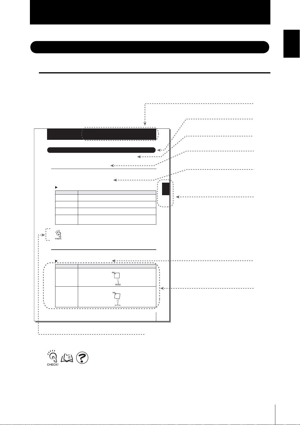
Page Format
Introduction
Editor's Note
Introduction
Title of each section
Header
Setting the Sensing Conditions
Section 3
Setting the Sensing Conditions
Set the conditions to be used for detecting workpieces by the sensor.
Setting the Measurement Mode
Set the measurement mode.
Select the measurement mode based on the items (e.g. speed, precision, or sensitivity)
that you want to give priority to in measurement.
FUN Mode - [SENSING] - [MODE]
Setting Description
STANDARD This is the standard measurement mode. (measurement cycle: approx. 500 s)
HIGH PRECISION Select this mode to measure workpieces at high precision. (measurement cycle:
HIGH SPEED Select this mode to measure workpieces at high speed. (measurement cycle: max.
HIGH SENSITIVITY Select this mode to measure workpieces with sensitivity set high. In this measure-
Setting the Head Installation
Set how the Sensor Head is installed.
FUN Mode - [SENSING] - [HEAD SENSOR]
Diffuse REFLECTION Select this item when the Sensor Head is installed for diffuse reflection sensing.
Regular REFLECTION Select this item when the Sensor Head is inst
(default)
approx. 2 ms)
speed approx. 110
ment mode, sensitivity to received light is much better than the HIGH PRECISION
mode as the sampling period is longer. (measurement cycle: approx. 4 ms)
In the HIGH SPEED mode, the measurement cycle changes according the actual settings. (When
only the average count is set, the measurement cycle becomes the maximum speed (approx. 110
s).) Check the actual measurement cycle at [INFO]-[CYCLE] under the top menu.
Setting Description
(default value)
s)
alled for regular reflection sensing.
Overview
Cross-header
Overview of the
cross-header
Section 3 SETUP
Index label
Indicates the section
number and title.
Movement
through menus up
to setting items
Explanation of
options
Supplementary Explanation
Helpful information regarding operation and reference
pages are introduced here using symbols.
*This page has been made purely for explanatory purposes and does not exist.
ZS-L
User’s Manual
3-11
ZS-L
User’s Manual
9

Introduction
Introduction
Editor's Note
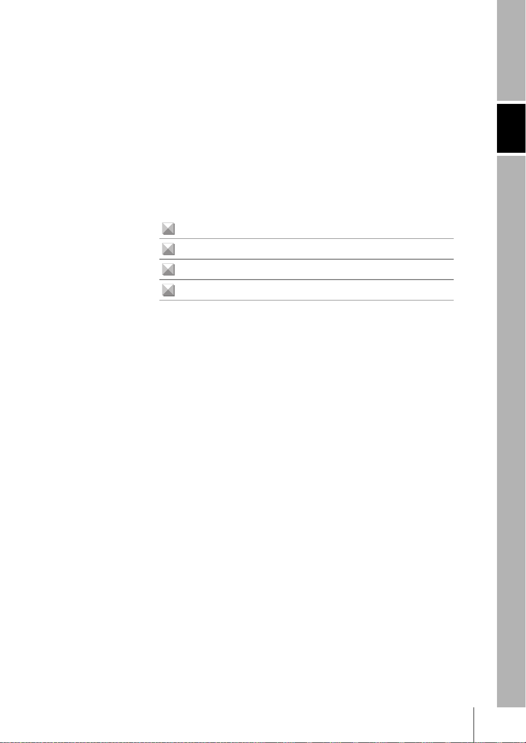
■ Meaning of Symbols
Menu items that are displayed on the Sensor Controller’s LCD screen, and windows,
dialog boxes and other GUI elements displayed on the PC are indicated enclosed by
brackets [aa].
■ Visual Aids
Indicates points that are important to ensure full product performance, such as operational
precautions and application procedures.
Indicates pages where related information can be found.
Indicates information helpful in operation.
10
ZS-L
User’s Manual

READ AND UNDERSTAND THIS DOCUMENT
CONTENTS
CONTENTS
CONTENTS
Meanings of Signal Words 5
Meanings of Alert Symbols 5
Alert statements in this Manual 5
Precautions for Safe Use 6
Precautions for Correct Use 7
Editor's Note 9
Page Format 9
CONTENTS 11
Section 1 FEATURES 1-1
ZS-L Features 1-2
ZS-L Applications 1-4
Basic Configuration 1-9
Part Names and Functions 1-10
Section 2 INSTALLATION & CONNECTION 2-1
About Installation and Connection 2-2
Section 1 Section 2 Section 3 Section 4 Section 5 Section 6 Section 7
Sensor Controller 2-3
Attaching the ferrite core 2-3
Installing the Sensor Controller 2-4
About the I/O cable 2-7
Sensor Head 2-11
Attaching the ferrite core 2-11
Installing the Sensor Head 2-12
Connecting Sensor Heads 2-18
SmartMonitor ZS 2-19
Installing SmartMonitor ZS on a personal computer 2-19
Starting up SmartMonitor ZS 2-23
Section 3 SETUP 3-1
Setting Flow 3-2
About Setup 3-4
Basic Knowledge for Operation 3-4
ZS-L
User’s Manual
11

READ AND UNDERSTAND THIS DOCUMENT
CONTENTS
CONTENTS
List of Setting Items 3-9
Setting the Sensing Conditions 3-12
Setting the Measurement Mode 3-12
Setting the Head Installation 3-13
Setting the Emitted Light Intensity 3-13
Setting the Measurement Object 3-14
Setting Prevention of Mutual Interference 3-16
Setting Gain 3-17
Setting the Filter Function 3-18
Setting Smooth 3-18
Setting Average 3-19
Setting Differentiation 3-19
Setting Output Processing of Sensing Information 3-20
Setting Scaling 3-20
Setting Hold Functions 3-24
Setting Zero Reset 3-28
Setting Threshold Values 3-31
Setting the Display Method 3-32
Setting the Digital Displays 3-32
Setting the LCD Display 3-33
HELP 3-34
Setting Banks 3-34
Switching banks 3-34
Clearing banks 3-34
Setting the System Environment 3-35
Saving setup data 3-35
Initializing setup data 3-35
Checking Sensor Controller information 3-36
Setting key lock 3-36
Setting the sensor load method 3-36
12
Setting the display language 3-37
ZS-L
User’s Manual

READ AND UNDERSTAND THIS DOCUMENT
CONTENTS
Section 4 EXTERNAL I/O 4-1
Linear Input/Output 4-2
Setting Linear Output 4-2
Setting Judgment Output 4-5
Non-Measurement Settings 4-6
Input Signal Settings 4-7
I/O Assignment Settings 4-7
Timing Charts 4-9
RS-232C Input/Output 4-11
RS-232C Specifications 4-11
Setting the Communication Specifications 4-12
Section 5 APPLICATION SETTING EXAMPLES 5-1
Measuring the Front Side of Black Sheet Rubber 5-2
CONTENTS
Section 1 Section 2 Section 3 Section 4 Section 5 Section 6 Section 7
Measuring the Height of a PCB Surface 5-5
Measuring the Thickness of Glass 5-7
Section 6 APPENDIX 6-1
Troubleshooting 6-2
Error Messages and Countermeasures 6-3
Q&A 6-5
Glossary 6-6
Specifications and External Dimensions 6-7
Sensor Head 6-7
Sensor Controller 6-18
Panel Mount Adapters 6-20
RS-232C Cable for Connecting to a Personal Computer 6-21
Extension Cable 6-22
Laser Safety 6-23
Requirements from Regulations and Standards 6-24
Summary of Requirements to Manufactures 6-24
Summary of Requirements to User 6-28
Definitions of Laser Classification 6-31
Engineering Data 6-33
ZS-L
User’s Manual
13

READ AND UNDERSTAND THIS DOCUMENT
CONTENTS
CONTENTS
Linearity Characteristic by Materials 6-33
Version Up Information 6-42
INDEX 6-43
Revision History 6-47
14
ZS-L
User’s Manual
Section 1 FEATURES
ZS-L Features 1-2
ZS-L Applications 1-4
Basic Configuration 1-9
Part Names and Functions 1-10
Section 1 FEATURES
ZS-L
User’s Manual
1-1
Section 1
r
(6)
r
ZS-L Features
ZS-L Features
Section 1 FEATURES
The ZS-L Series is a 2D CMOS laser type displacement sensor. It is provided with a highperformance sensing function that uses a 2D CMOS image sensor, features a high-speed
transmission capability free from data degradation as a result of 100% digital handling of
data, and is extremely easy-to-use and handy.
(3)
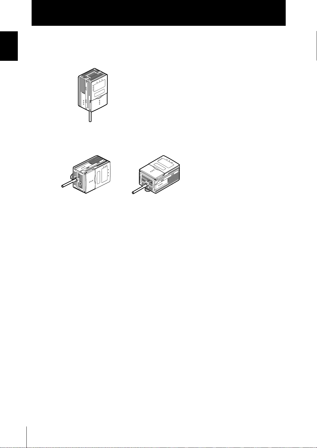
Sensor Head
(1)
(2)
(4)
Sensor Controlle
(5)
Personal compute
(1) Compact Sensor Head
A 2D CMOS image sensor, proprietary algorithms, and other sensing technology are
incorporated in the compact Sensor Head. This achieves an improved dynamic range,
high-speed sampling up to 110 µs, and a high resolution.
(2) An Enhanced Lineup of Sensor Heads
Regular Reflection Type Diffuse Reflection Type
ZS-LD20T ZS-LD40T ZS-LD50 ZS-LD80 ZS-LD200
Measurement
distance:
20±1 mm
Measurement
distance:
40±2.5 mm
Measurement
distance:
50±5mm
Measurement
distance:
80±15 mm
Measurement
distance:
200±50 mm
ZS-L
1-2
User’s Manual
Section 1
ZS-L Features
(3) High-speed Digital Transfer
The LVDS (Low Voltage Differential Signaling) high-speed communication interface is
used (an industry first) between the Sensor Head and the Sensor Controller. Data
detected by the Sensor Head is transferred at high speed without any degradation.
Moreover, the connection can be extended up to 22 m by 2 extension cables to suit
your setup environment.
Connection extended up to 22 m p.1-7
(4) Business Card-size Sensor Controller
• The Sensor Controller is designed to be compact so that it can be installed at a wide
range of sites.
External Dimensions p.6-18
• Large-size LCD screen and direct function keys ensure outstanding operability.
• The Sensor Controller supports various workpieces, which means that detailed and
flexible settings can be made.
• Incorporates extensive functions such as Filter and Hold to support a wide range of
applications.
• Mutual interference from 2 adjacent Sensor Heads can be prevented by shifting the
timing of laser beam emission.
Section 1 FEATURES
List of Setting Items p.3-9
(5) USB Connection
The Sensor Controller is provided with a USB port (compliant with Full-Speed USB2.0
specifications) as standard. This enables detection data and setting data to be easily
uploaded to a personal computer.
(6) Dedicated Software “SmartMonitor ZS Professional”
The “SmartMonitor ZS Professional” software for setting up and monitoring multi-window displays and logging is provided (Sold separately). This software also supports the
display and setup of data such as monitoring of waveforms and designation of area that
is not possible on the Sensor Controller alone.
ZS-L
User’s Manual
1-3
Section 1
ZS-L Applications
ZS-L Applications
Section 1 FEATURES
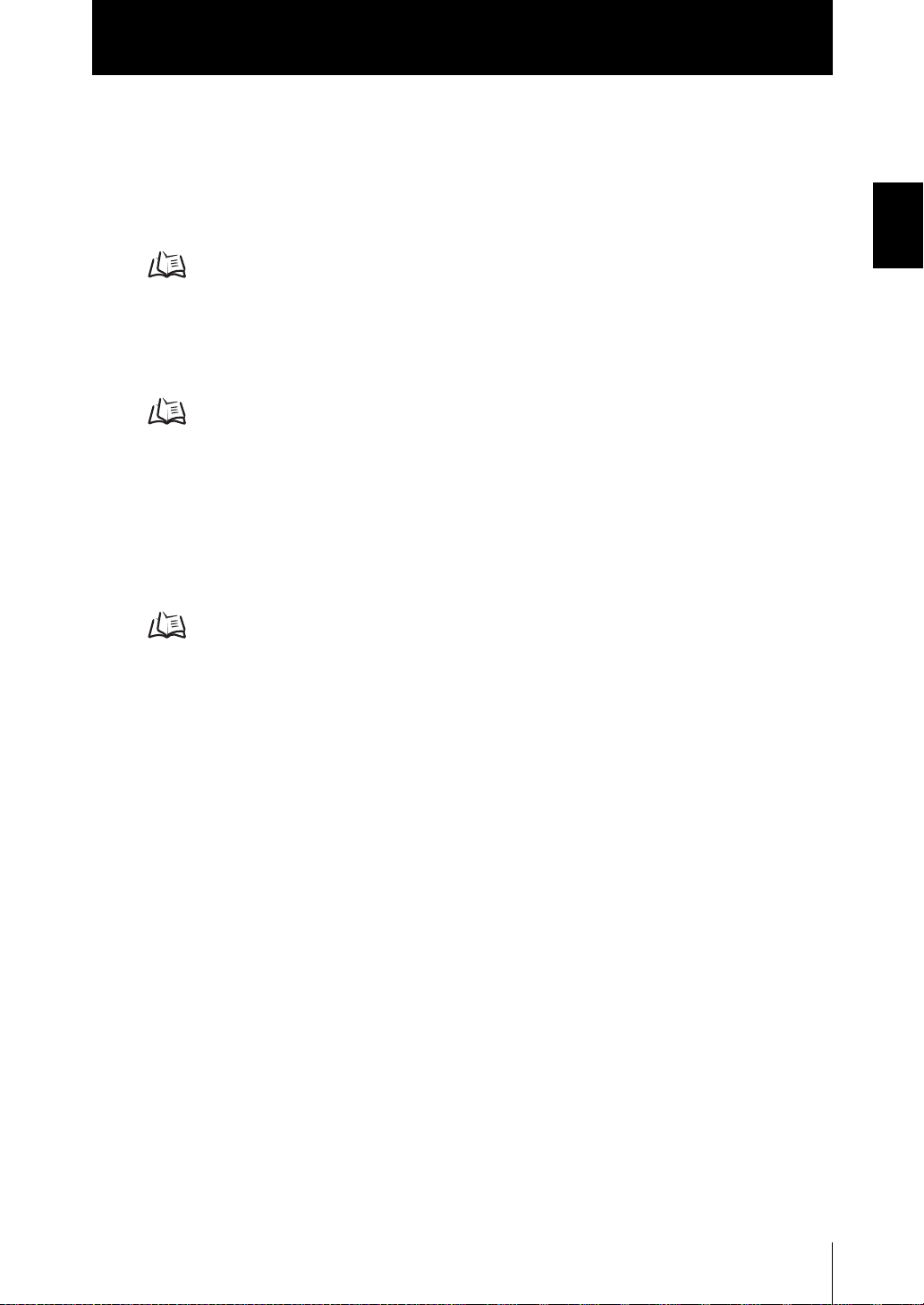
● Detection of rubber and other black workpieces
The improved dynamic range enables the detection of black workpieces that reflect little light.
● Detection of light-penetrating workpieces such as PCBs
Proprietary sensing algorithms enable the detection of workpieces through which light
penetrates.
1-4
● Detection of transparent workpieces such as glass
Proprietary sensing algorithms enable the detection of workpieces through which light
passes through.
Up to 3 sheets of glass can be detected, which means that the glass thickness and gap
between glass sheets can be measured.
ZS-L
User’s Manual
Section 1
ZS-L Applications
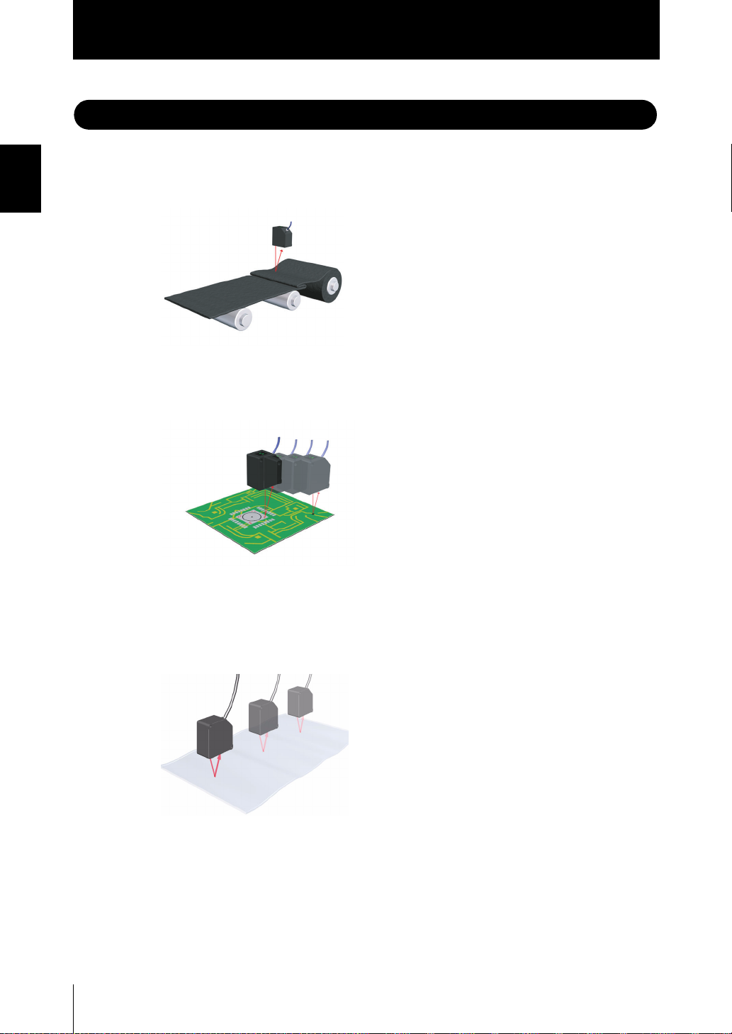
● Detection of mirror-surface workpieces such as HDDs
Workpieces having strong directivity of reflected light can be detected by a regular
reflection type Sensor Head.
● Display of various measurement information
Various measurement information can be displayed on the sub-display (lower section)
on the Sensor Controller.
LCD screens can be customized to change the display of desired information to easierto-understand terminology.
Section 1 FEATURES
Switches various measurement information
by one-touch operation.
Threshold value
Present value
LD ON ZERO ENABLE
H
P
L
MAIN :MESURE
SUB :THRESH
Voltage/current value
Displays measured values.
Customizes display details.
EQPNo.
OMRON_1UNIT
Resolution
Received light amount
ZS-L
User’s Manual
1-5
Section 1 FEATURES
Section 1
ZS-L Applications
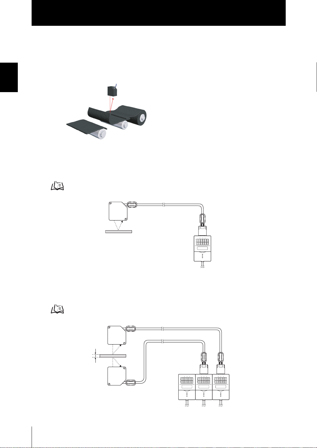
● Installable away from the sensing object
The ZS-L Series can be installed up to 95 mm (ZS-LD80) or up to 250 mm (ZS-LD200)
away from the measuring point. This allows workpieces to be measured at a position
that is not influenced by the workpiece flying up or the interference of peripheral mechanisms.
The ZS-L Series can be installed at positions
that will not be affects by the rubber belt
being cut or flying back which occurs during
emergency stops.
● Simple Measurement of Glass Thickness and Gap between Glass
Two settings, [THICK] for measuring the thickness of glass and [GAP] for measuring
the gap between glass, are provided as sensing object options. Just selecting these
options allows you to set measurement conditions simply.
Setting the Measurement Object p.3-14
Glass
LD ON ZERO ENABLE
H
P
L
● Mutual Interference Prevented
Mutual interference between 2 Sensor Heads can be prevented by shifting the laser
beam emission timing.
Setting Prevention of Mutual Interference p.3-16
Glass
LD ON ZERO ENABLE
LD ON ZERO ENABLE
LD ON ZERO ENABLE
H
P
L
H
H
P
P
L
L
1-6
ZS-L
User’s Manual
Section 1
ZS-L Applications
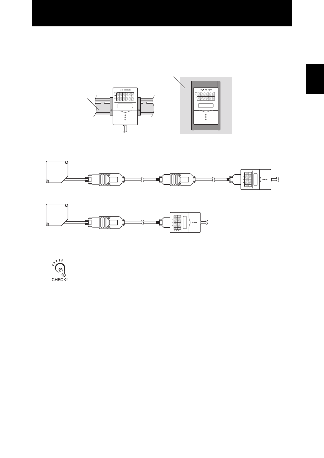
● Installable on DIN Track or Panels
The ZS-L Series can be installed on a DIN track and on a control panel or other panels
using the optional Panel Mount Adapter.
Panel
DIN track
● Connection Extendable up to 22 m
The connection can be extended up to 22 m to suit your setup environment.
Section 1 FEATURES
ZS-LD
ZS-LD
Sensor
cable
Sensor
cable
Extension cable
(ZS-XC_B(R))
Extension cable
(ZS-XC_A)
(ZS-XC_B(R))
LD ON ZERO ENABLE
H
P
L
ZS-LDC
Extension cable
(ZS-XC_B(R))
LD ON ZERO ENABLE
H
P
L
ZS-LDC
• Only the ZS-XC_B(R) cable allows this extended connected.Note, however, that the connection
with the ZS-XC_A cannot be extended.
• The cable may break at locations when it is made to bend. So, use the robot cable type Extension
Cable (ZS-XC5BR).
ZS-L
User’s Manual
1-7
Section 1 FEATURES
Section 1
ZS-L Applications
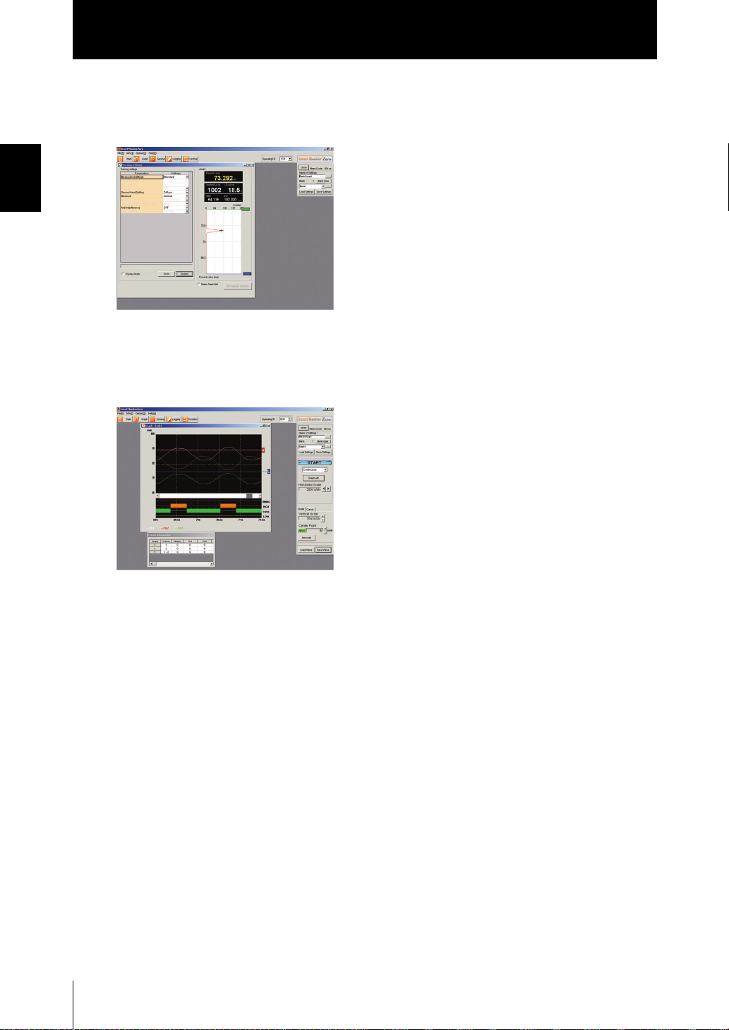
SmartMonitor ZS enables the following:
● Easy Sensor Controller setup and log management
Measurement conditions can be set up, and settings saved, read or copied.
* The screen show here may differ from the actual screen.
● Real-time verification of changes in detection workpiece height
The measurement conditions can be changed while verifying the measurement state
by a waveform.
* The screen shown here may differ from the actual screen.
1-8
ZS-L
User’s Manual
Basic Configuration
Section 1
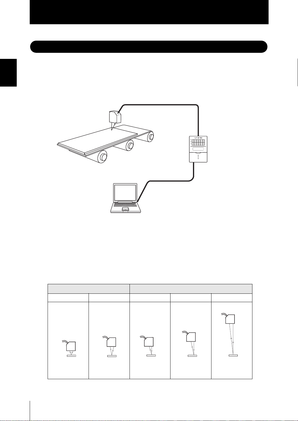
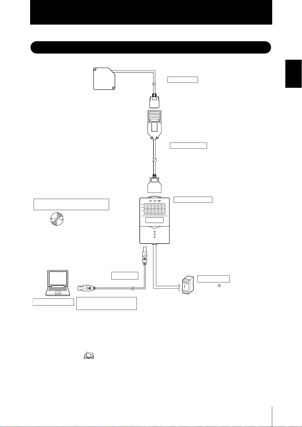
Basic Configuration
The figure below shows the Basic Configuration of the ZFV Series.
Sensor Head
ZS-LD20T/LD40T/LD50/LD80/LD200
Detects the sensing object.
*1
Extension Cable
ZS-XC1A(1m)/XC4A(4m)/XC8A(8m)
ZS-XC5B(5m)/XC10B(10m)/XC5BR(5m)
This is used between the Sensor Head
and Sensor Controller.
On the ZS-XC_B(R), the connection can be
extended by two cables. (max. 22 m)
SmartMonitor ZS Professional
(option software, sold separately)
ZS-SW11E
Allows you to operate the
Sensor Controller, monitor
or log measured values from
the personal computer.
In this manual, the software is
referred to as "SmartMonitor ZS".
Sensor Controller
ZS-LDC11/LDC41
Performs measurement, and outputs
measurement results.
Section 1 FEATURES
Personal computer
*1 Only two of the ZS-XC_B(R) cables can be connected in series.
This is not possible on the ZS-XC_A. Cables may break at locations
where bending occurs on the cable. Use the robot cable type extension cable (ZS-XC5BR).
USB cable
RS-232C cable for personal
computer connection
ZS-XRS2
This is used for communicating
with a personal computer without
a USB port.(SmartMonitor ZS cannot be
used on the RS-232C interface.
Communication using CompoWay/F or
non-procedural protocol is possible.)
p.4-11
Power Supply
DC24V ( 10%)
Recommended parts
(1) When 1 Sensor Controller is
connected
S82K-01524 (DC24V, 0.6 A)
(2) When 2 to 3 Sensor Controllers are
connected
S82K-05024 (DC24V, 2.1 A)
(3) When 4 to 10 Sensor Controllers
are connected
S82K-01524 (DC24V, 0.6 A)
Prepare the required number of (1)
and (2) power supplies above.
ZS-L
User’s Manual
1-9
Section 1
Part Names and Functions
Part Names and Functions
Section 1 FEATURES
The following describes the names and functions of parts on the Sensor Controller and
Sensor Head.
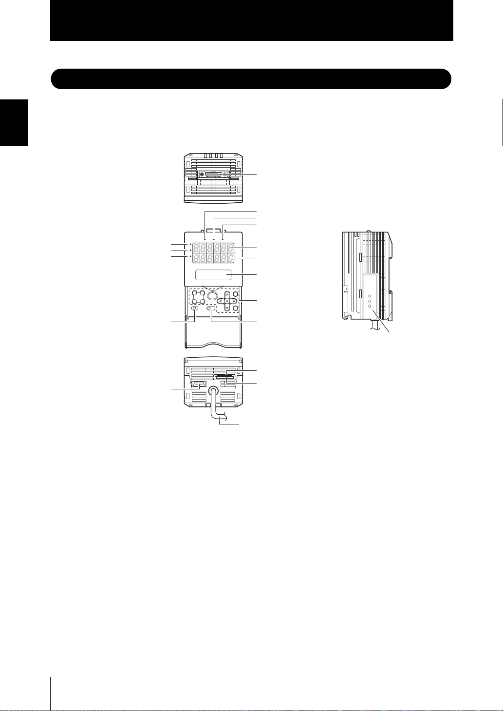
■ Sensor Controller
(13) Sensor Head connector
(1) Laser indicator
(2) Zero Reset indicator
(3) ENABLE indicator
(12) HIGH indicator
(11) PASS indicator
(10) LOW indicator
(18) USB port
H
P
L
LD ON ZERO ENABLE
(4) Main display
(5) Sub-display
(6) LCD screen
(7) Control keys
(8) Mode switch(9) Threshold switch
(14) Coupler
(15) RS-232C connector
(16) Voltage/current switch
1-10
(17) I/O cable
(1) Laser indicator
The Laser indicator is lit while the Sensor Head is emitting a laser beam.
(2) Zero Reset indicator
The Zero Reset indicator is lit when the zero reset function is enabled.
(3) ENABLE indicator
The ENABLE indicator lights when the Sensor is ready for measurement. It goes off
when measurement is not possible (e.g. when the received light amount is excessive or
insufficient, when the measuring range is exceeded, when the Sensor Head is not connected, or when measurement is not being performed in the FUN mode).
(4) Main Display
The Main Display shows measured values.
(5) Sub-display
The sub-display shows thresholds and additional information during measurement.
ZS-L
User’s Manual
Section 1
Part Names and Functions
(6) LCD screen
RUN Mode :Displays additional information for the main display and the setup menu
for display related information.
TEACH Mode:Displays the menu for setting up the thresholds.
FUN Mode :Displays the measurement condition setup menu.
(7) Control keys
The Control Keys are for setting measurement conditions and other information. The
functions assigned to the Control Keys change according to the operating mode.
Displays and Key Operations p.3-5
(8) Mode Switch
The Mode Switch selects the operating mode.
RUN mode : Select this mode when performing regular measurement.
TEACH mode : Select this mode when setting the judgment thresholds.
FUN mode : Select this mode when setting measurement conditions.
(9) Threshold Selector Switch
The Threshold Selector switch selects whether to set (or display) the HIGH or LOW
threshold.
Section 1 FEATURES
(10) LOW indicator
The LOW indicator is lit when the condition “measured value < LOW threshold” is satisfied.
(11) PASS indicator
The PASS indicator is lit when the condition “LOW threshold ≤ measured value ≤ HIGH
threshold” is satisfied.
(12) HIGH indicator
The HIGH indicator is lit when the condition “HIGH threshold < measured value” is satisfied.
(13) Sensor Head connector
This connector connects the Sensor Head.
(14) Coupler
This connector is used to connect two or more Sensor Controllers. It is located on both
sides of the Sensor Controller.
(15) RS-232C connector
Connect the RS-232 cable when you are connecting the Sensor Controller to a personal computer that does not have a USB port.
(16) Voltage/Current switch
The Voltage/Current switch selects between voltage output and current output.
Before operating this switch, make sure that the Sensor Controller is turned OFF. Also, make sure
that the load connected to “linear output wire (co-axial) – linear GND wire” satisfies the rating of the
set state (voltage or current output) before turning the Sensor Controller ON. Otherwise, the Sensor
Controller may be damaged.
Rating of connected load (I/O Circuit Diagrams) p.2-9
ZS-L
User’s Manual
1-11
Section 1 FEATURES
Section 1
Part Names and Functions
(17) I/O Cable
The I/O cable connects the Sensor Controller to the power supply and external
devices, such as timing sensors or programmable controllers.
(18) USB port
Connect the USB cable to the USB port to connect to a personal computer.
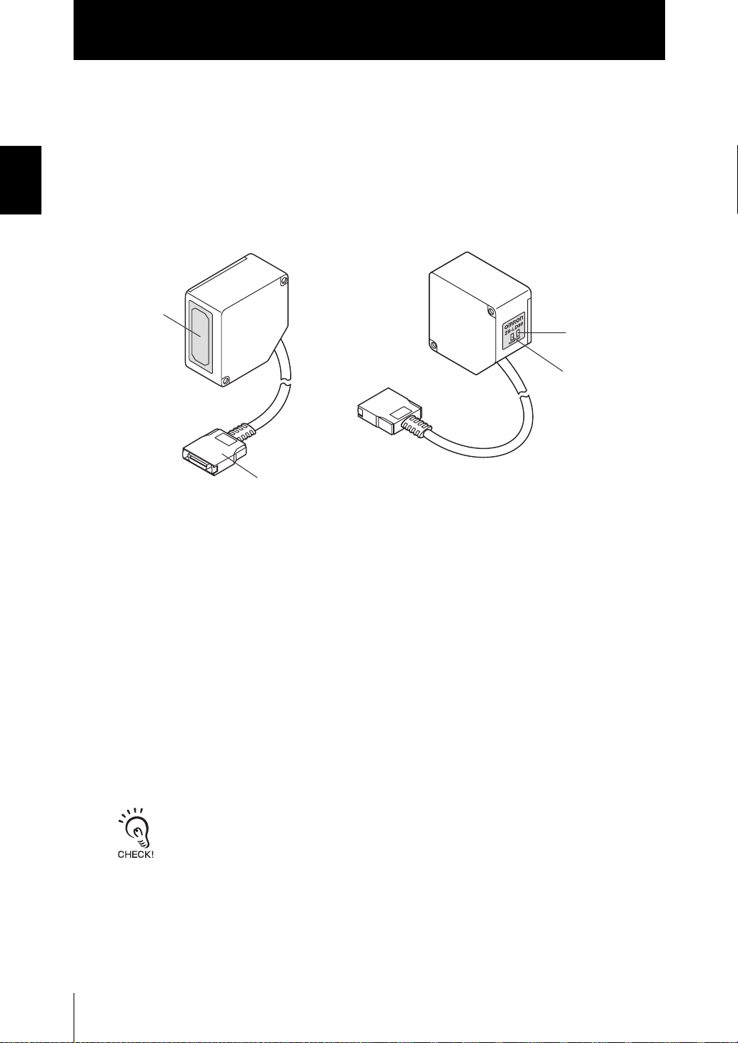
■ Sensor Head
(1) Laser emitter/
receiver section
(3) FAR indicator
(4) NEAR indicator
(2) Connector
(1) Laser Emitter/Receiver Section
This is the section that emits the laser beam and receives reflected light.
(2) Connector
To be connected to the Sensor Controller
(3) FAR indicator, (4) NEAR indicator
These indicators lit as follows according to the distance between the front of the Sensor
Head and workpiece.
Both NEAR and FAR indicators are lit : Measuring center distance ±
(measuring range x 10%)
NEAR indicator is lit : Near side within measuring range
FAR indicator is lit : Far side within measuring range
NEAR and FAR indicators are flashing : Outside measuring range
These indicators also function as laser alarm indicators.
• At least either of these indicator lights or flashes after the Sensor Head is turned ON.
• Both indicators go out for 15 to 25 seconds after the Sensor Head is turned ON to indicate that the
laser beam is OFF.
• Either of these indicators lit or flashes while the laser beam is being emitted.
• Both indicators go out when the laser beam is OFF.
1-12
ZS-L
User’s Manual
Section 2 INSTALLATION & CONNECTION
About Installation and Connection 2-2
Sensor Controller 2-3
Attaching the ferrite core 2-3
Installing the Sensor Controller 2-4
About the I/O cable 2-7
Sensor Head 2-11
Attaching the ferrite core 2-11
Installing the Sensor Head 2-12
Connecting Sensor Heads 2-18
SmartMonitor ZS 2-19
Installing SmartMonitor ZS on a personal computer 2-19
Starting up SmartMonitor ZS 2-23
Section 2 INSTALLATION & CONNECTION
ZS-L
User’s Manual
2-1

Section 2
About Installation and Connection
About Installation and Connection
■ Checking the installation environment
Read “Precaution for Safe Use” at the beginning of this manual, and check the installation environment.
Section 2 INSTALLATION & CONNECTION
■ Checking the installation site
Read “Precaution for Correct Use” at the beginning of this manual, and check the
installation site.
■ About the power supply
Before installing and connecting the Smart Sensor, be sure to turn it OFF.
Also read “Precaution for Safe Use” and “Precaution for Correct Use” at the beginning
of this manual, and check the power supply and wiring.
2-2
ZS-L
User’s Manual
 Loading...