

Omron ZN-A2502, ZN Series, ZN-A2502D, ZN-A4105D, ZN-A4105 System Manual
...
Clean Sensing System
ZN Series
System Manual
Cat. No. Z267-E1-01

Introduction
Thank you for purchasing the ZN.
This manual provides only information, such as system components and setup procedures, that
is required when using the ZN Series in a system.
For details on product functions, performance and handling methods of individual products, refer
to the Instruction Sheet packaged with the respective product.
When using the ZN, be sure to observe the following:
• The ZN must be operated by personnel knowledgeable in electrical engineering.
• To ensure safe use of the product, please read the Instruction Sheet packaged with each
product and this manual to deepen your understanding of the product.
• Please keep this manual and the Instruction Sheet packaged with each product in a safe place
so that they can be referred to whenever necessary.

Introduction
Section 1
Section 2
Section 3
Section 4
APPLICATION CONSIDERATIONS (Please Read)
FEATURES
UPGRADING THE SYSTEM
BASIC KNOWLEDGE OF CLEAN SENSING SYSTEMS
APPENDICES
Introduction
‚Í‚¶‚ß‚É ‘æ 1 Í‘æ 2 Í‘æ 3 Í‘æ 4 Í
Section 1 Section 2 Section 3 Section 4
System Manual
Clean Sensing System
ZN Series

Introduction
Introduction
READ AND UNDERSTAND THIS DOCUMENT
Please read and understand this document before using the products. Please consult your OMRON
representative if you have any questions or comments.
WARRANTY
OMRON’s exclusive w arranty is that the products are f ree from defects in materials a nd workmanship for a
period of one year (or othe r pe ri od if specified) from date of sale by OMRO N .
OMRON MAKES NO WARRANTY OR REPRESENTATION, EXPRESS OR IMPLIED, REGA RDING NONINFRINGEMENT, MERCHANTABILITY, OR FITNESS FOR PARTICULAR PURPOSE OF THE PRODUCTS.
ANY BUYER OR USER ACKNOWLEDGES THAT THE BUYER OR USER ALONE HAS DETERMINED THAT
THE PRODUCTS WILL SUITABLY MEET THE REQUIREMENTS OF THEIR INTENDED USE. OMRON
DISCLAIMS ALL OTHER WARRANTIES, EXPRESS OR IMPLIED.
LIMITATIONS OF LIABILITY
OMRON SHALL NOT BE RESPONSIBLE FOR SPECIAL, INDIRECT, OR CONSEQUENTIAL DAMAGES,
LOSS OF PROFITS OR COMMERCIAL LOSS IN ANY WAY CONNECTED WITH THE PRODUCTS,
WHETHER SUCH CLAIM IS BASED ON CONTRACT, WARRANTY, NEGLIGENCE, OR STRICT LIABILITY.
In no event shall responsi bility of OMRON for any act exceed the individual price of the product on which
liability is asserted.
IN NO EVENT SHALL OMRON BE RESPONSIBLE FOR WARRANTY, REPAIR, OR OTHER CLAIMS
REGARDING THE PRODUCTS UNLESS OMRON’S ANALYSIS CONFIRMS THAT THE PRODUCTS WERE
PROPERLY HANDLED, STORED, INSTALLED, AND MAINTAINED AND NOT SUBJECT TO
CONTAMINATION, ABUSE, MISUSE, OR INAPPROPRIATE MODIFICATION OR REPAIR.
SUITABILITY FOR USE
THE PRODUCTS CONTAINED IN THIS DOCUMENT ARE NOT SAFETY RATED. THEY ARE NOT DESIGNED OR
RATED FOR ENSURING SAFETY OF PERSONS, AND SHOULD NOT BE RELIED UPON AS A SAFETY COMPONENT OR PROTECTIVE DEVICE FOR SUCH PURPOSES.
Please refer to separate catalogs for OMRON’s safety rated products.
OMRON shall not be responsible for conform ity with any standards, codes, or regulations that apply to th e
combination of produc ts in the customer’s application or us e of th e pr oduct.
At the customer’s request, OMRON will provide applicable third party certification documents identifying ratings
and limitations of use that apply to the products. This information by itself is not sufficient for a complete
determination of the suitability of the produ cts in comb ination w ith the en d produc t, machi ne, syste m, or other
application or use.
The following are some examples of applications for which particular attention must be given. This is not
intended to be an exhaustive list of all possible uses of the products, nor is it intended to imply that the uses
listed may be suitable for the p ro ducts:
• Outdoor use, uses inv olving potential chemical contamination or electrical interference, or conditions or
uses not described in this document.
ZN
System Manu al
ii

Introduction
• Nuclear energy control systems, combustion systems, railroad systems, aviation systems, medical
equipment, amu sem ent ma chi ne s, v eh ic le s, saf et y eq ui pme nt , an d ins t al la t io ns su bj ec t t o separate industry
or government regulations.
• Systems, machin es, and equipment that could present a ris k to lif e or pro per t y.
Please know and obse rv e all p ro hi bi tio ns of use applicable to the products.
NEVER USE THE PRODUCTS FOR AN APPLICATION INVOLVING SERIOUS RISK TO LIFE OR
PROPERTY WITHOUT ENSURING THAT THE SYSTEM AS A WHOLE HAS BEEN DESIGNED TO
ADDRESS THE RISKS, AND THAT THE OMRON PRODUCT IS PROPERLY RATED AND INSTALLED FOR
THE INTENDED USE WITHIN THE OVERALL EQUIPMENT OR SYSTEM.
PERFORMANCE DATA
Performance data given in this document is provided as a guide for the user in determining suitability and does
not constitute a warranty. It may represent the result of OMRON’s test conditions, and the users must correlate
it to actual application requirements. Actual performance i s su bj ect t o th e O M RO N Warranty and Limitations of
Liability.
CHANGE IN SPECIFICATIONS
Product specifications and accessories may be changed at any time based on improvements and other
reasons.
Introduction
It is our practice to change model numbers when published ratings or features are changed, or when significant
construction chang es are made. However, some specifications o f the product may be changed without any
notice. When in do ubt, special m odel numbe rs may be a ssigned to fix or establish key s pecificat ions for your
application on your request. Please consu lt with your OMRON repres entative at any time to conf irm actual
specifications of purchased products.
DIMENSIONS AND WEIGHTS
Dimensions and weights are nominal and are not to be used for manufacturing purposes, even when
tolerances are shown.
ERRORS AND OMISSIONS
The information in this do cument has been carefully checked and i s believed to be accurate; however, no
responsibility is assum ed for clerical, typographical, or proofreading errors, or omissions.
PROGRAMMABLE PRODUCTS
OMRON shall not be responsible for the user’s prog ra m m in g of a pro gr ammable product, or any conse quence
thereof.
COPYRIGHT AND COPY PERMISSION
This document shall not be copied for sales or promotions w ithout permission.
This document is protected by copyri ght and is inten ded solely for use in conjunc tion with the pr oduct. P lease
notify us before cop ying or reproducing this docum ent in any manner, for any other purpose. I f copying or
transmitting this document to another, please copy or transmit it in its entirety.
ZN
System Manu al
iii

Introduction
Precautions for Safe Use
Introduction
Precautions for Safe Use
The following points are important to ensure safety, so make sure that they are strictly observed.
■ Power Supply and Wiring
• When connecting multiple Air Clean Units to build a system, use a commercially
available LAN cable (straight type: Category 5E or higher).
• On models that can be connecte d t o A ir Clea n Units, such as the Air P artic le S ens or
(ZN-PDA12) and Interfac e Unit (ZN-SF12), use the cable from the body to directly
connect to the unit.
• To extend the cable mentioned above, a commercially available LAN connector
female to female, straight type) and a LAN cable (straight type: Category 5E or
higher) must be used.
• The cables must be 100 m or shorter in total length.
For details on other precautions for safe use and precautions for correct use,
refer to the Instruction Sheet for the respective device, and make sure that they
are strictly observed.
iv
ZN
System Manu al
Editor's Note
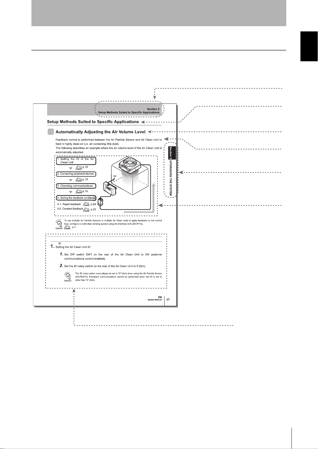
● Title of each section
● Header
● Cross-header
● Index label
● Overview and points of the
function described
● Operation procedure and supplementary explanat ion
Indicates the contents of the page.
Shows the chapter number and contents.
Shows the operation flow and setup
method.
Explains the operation procedure and the display status
resulting from execution of the operation.
Helpful information regarding operation and reference
pages is introduced here using symbols.
* This page does not exist.
● Overview of the section
Page Format
Introduction
Editor's Note
Introduction
System Manu al
ZN
v
Introduction
Editor's Note
Introduction
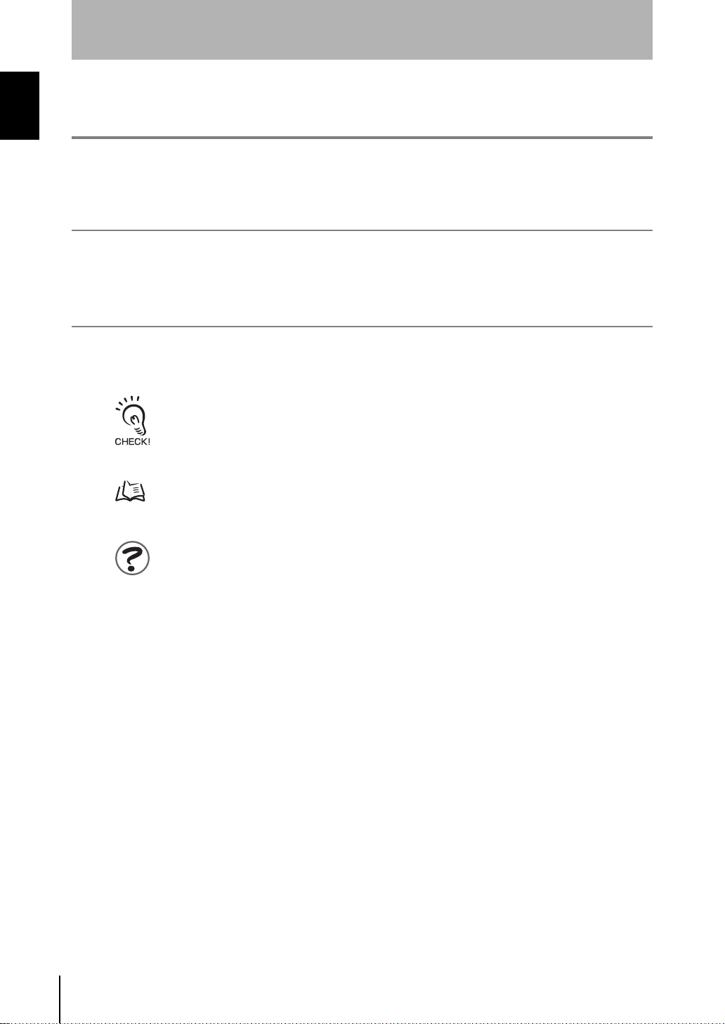
Notational Conventions
■ Menu
In this manual, menu items displayed on the screen are enclosed with [ ].
■ Operation procedure
Operation steps are numbered to indicate their order .
■ Visual Aids
Indicates points that are important to achieve the full product performance, such as operational
precautions and application procedures.
Indicates pages where related information can be found.
Indicates information helpful in operation.
vi
ZN
System Manu al

CONTENTS
Introduction
CONTENTS
Introduction
Precautions for Safe Use iv
Editor's Note v
Page Format v
Notational Conventions vi
CONTENTS vii
Section 1 FEATURES 1
What is the "Clean Sensing System?" 2
System Features 2
Features of the Clean Sensing System 4
System Configuration Examples 7
Direct Clean Sensing System 7
Multi-Clean Sensing System 11
CONTENTS
Section 2 UPGRADING THE SYSTEM 13
Before Upgrading the System 14
Flow of Operations for Upgrading the System 14
Installing the Exclusive Monitoring Software 15
Setup Methods Suited to Specific Applications 18
Automatically Adjusting the Air Volume Level 18
Monitoring/Logging the Amount of Particles 25
Detecting the Cleanliness of Multiple Processes 31
ZN
System Manu al
vii

Introduction
CONTENTS
Introduction
Section 3 BASIC KNOWLEDGE OF CLEAN SENSING SYSTEMS 35
Feedback Control 36
CONTENTS
What is "Feedback?" 36
How Feedback Control Works 40
Clean Sensing 44
Principle of "Particle Count" 44
What is "Cleanliness?" 45
Section 4 APPENDICES 47
Maintenance 48
Troubleshooting 50
Troubleshooting 50
Error Messages and Countermeasures 51
Specifications and Dimensions 53
List of Products 66
INDEX 69
Revision History 72
viii
ZN
System Manu al
Section 1
FEATURES
What is the "Clean Sensing System?" 2
System Features 2
Features of the Clean Sensing System 4
System Configuration Examples 7
Direct Clean Sensing System 7
Multi-Clean Sensi ng Sy st em 11
Section 1 FEATURES
System Manu al
ZN
1
Section 1
OPE1
OPE2
OPE3
■ Clean Monitoring System (ZN-SFW Series)
Monitoring the amount of particles at multiple points in
manufacturing processes is important in improving
product quality. By connecting Interface Units, you can
log the measured data of Air Particle Sensors at up to ten
locations at once on a personal computer.
The Electrostatic Sensor (ZJ-SD) also can be connected,
which means that you can al so asce rtain the re latio nship
between the amount of s tatic electricity and the amount
of particles.
The clean sensing system continuously s enses the amount of particles
in a clean boot h or cl ean b ench, and c ontrols the ai r vol ume le ve l of t he
Air Clean Unit. This way, it can easily ensure an environment having a
fixed cleanliness class at all times.
An environment for removing dust and neu tralizing static electri city can
be built by incorporating a new-concept Ionizer Unit in this system.
What is the "Clean Sensing System?"
What is the "Clean Sensing System?"
Section 1 FEATURES
System Features
OPE3
OPE2
OPE1
Z
N
S
F
12
ZN
System Manu al
2
What is the "Clean Sensing System?"
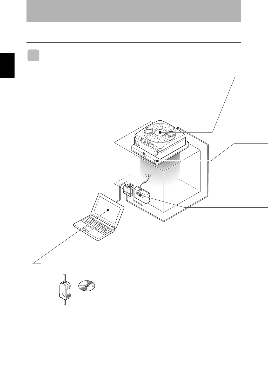
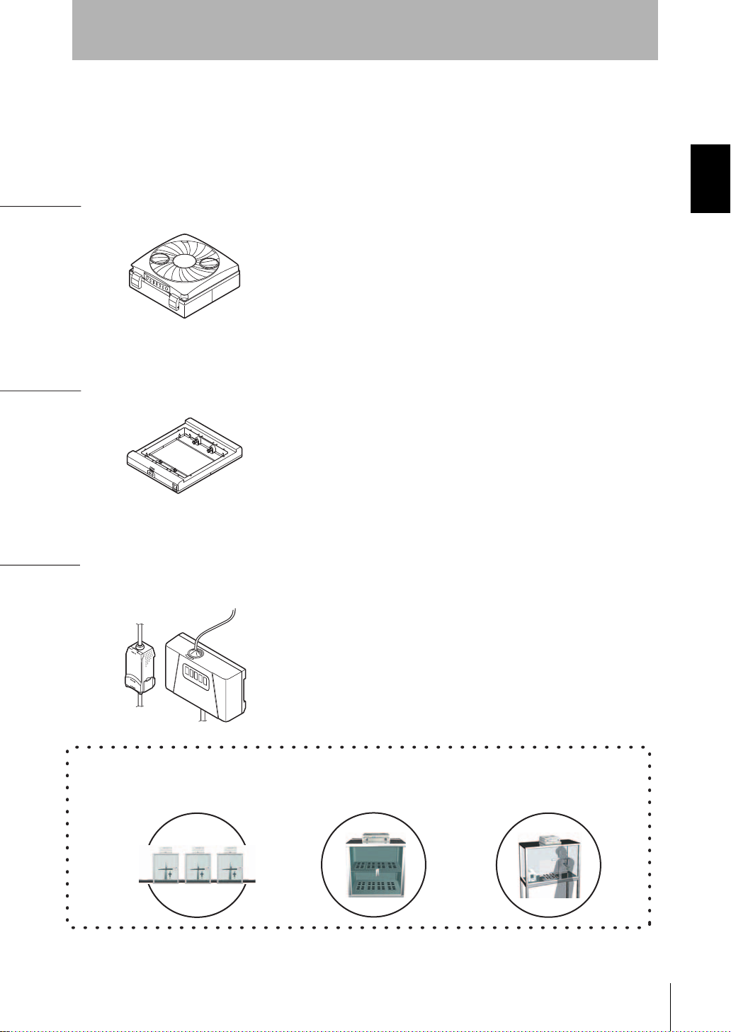
■ Air Clean Unit (ZN-A Series)
Unique twin-blower structure (ZN-A2502) achieves light weight
and large air volume.
Compact but more powerful.
Incorporating a clogged main filter (HEPA) detection function.
Visibility is improved by indicators located on two corners of
the body.
■ Air Particle Sensor (ZN-PD Series)
High-performance fan used for air suction to ensure
measurement at all times.
Use of a semiconductor laser and high-sensitivity optical
design in the sensor achieves measurement of minute
particles of 0.3 µm, 0.5 µm and 1.0 µm in diameter.
Thinnest in industry, large air volume
■ Ionizer Unit (ZN-J Series)
Directly mounted on Air Clean Unit
Open structure does not b lock the laminar ai rflow from the Ai r
Clean Unit.
No more troublesome wiring required. Installation man-hours
can be considerably reduced.
An industry first, one-touch dust removal and static neutralization
Smallest in industry, constant measuring
Main Applications
Electronic component
production processes
Storage or test
environments
Cell manufacturing
processes
Section 1
Section 1 FEATURES
System Manu al
ZN
3
Section 1
What is the "Clean Sensing System?"
Features of the Clean Sensing System
Section 1 FEATURES
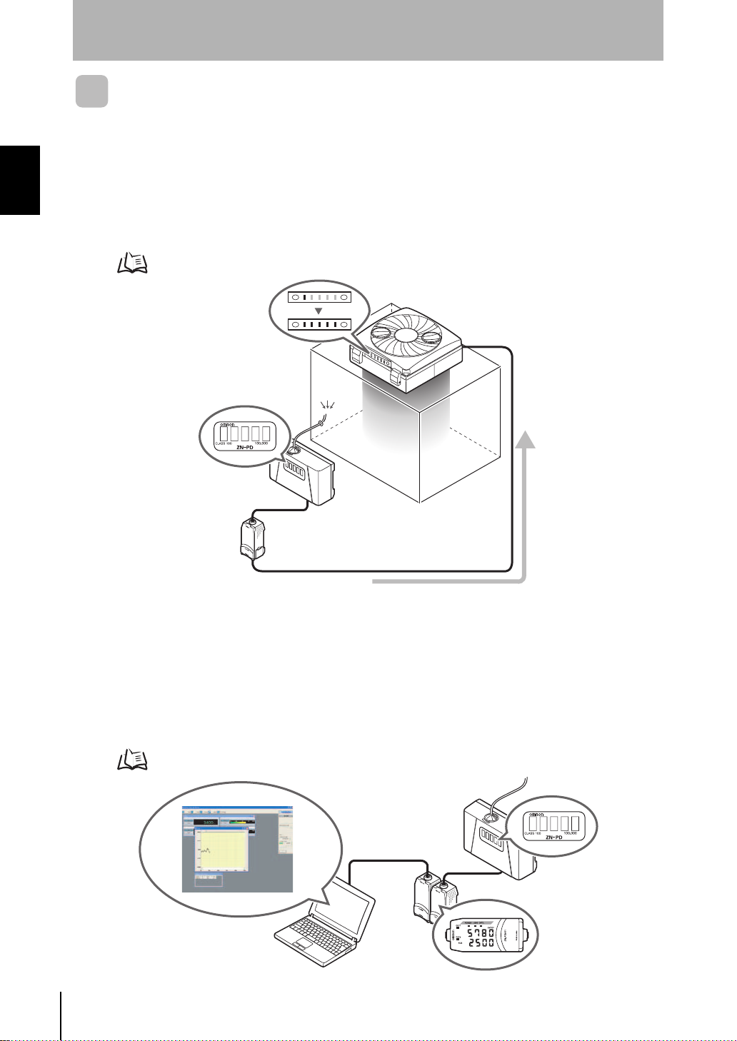
■ Feedback-based Automatic Adjustment of Air Volume
The air volume level of the Air Clean Unit can be automati cally controlled based on the
amount of particles measured by the Air Par ticle Sensor. The cleanli ness class in clean
booths can be maintained at the opt imum air volume level in propor tion to the amount of
particles from rapid air feed through to fine air volume operation in the power saving mode.
Setting Method p.18
4
■ Monitoring/Logging the Amount of Particles
The cleanlines s class i nside clean b ooths can be ver ified and ascertained by the amount of particle s
per unit volume. The amount of particles can be verified on the Sensor and the Amplifier Unit.
Measured values can be easily logged on a personal computer using Interface Units and the
exclusive monitoring software (Realtime Clean Air Monitor). Changes in the amount of particles
over time observed in this way can be made use of as data for improving product quality.
Setting Method p.25
ZN
System Manu al
OPE3
OPE2
OPE1
Section 1
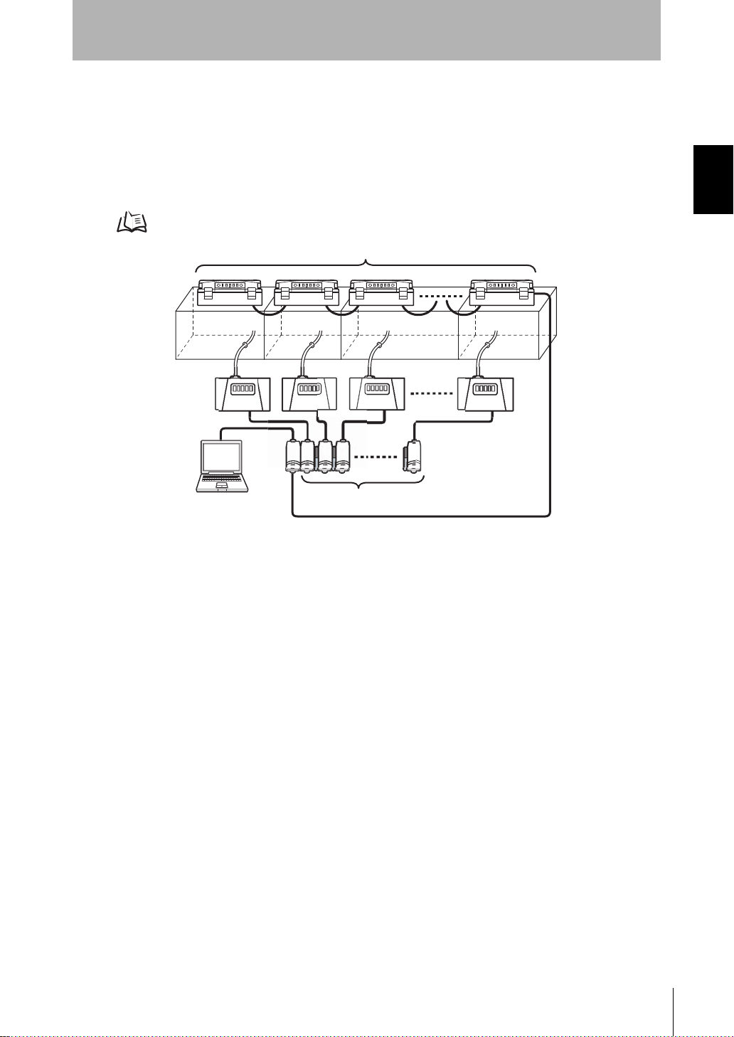
Max. 9 units connected
Max. 10 units connected
What is the "Clean Sensing System?"
■ Improving Product Quality by Multi-point Measurement
Since Air Clean Units and Air Particle Sensors can be conn ected to each other, the
amount of air particles in multiple clean booths installed in processes can be
comprehensively de tected and controlled. Which process is worseni ng in cleanliness
can be linked to quality control for continual management.
Setting Method p.31
Section 1 FEATURES
System Manu al
ZN
5
Section 1
Ion Balance Sensor
What is the "Clean Sensing System?"
■ Simultaneous Dust Removal and Static Neutralization
The Ionizer Unit ZN-J series, the first in industry to be added on later to an Air Clean
Section 1 FEATURES
Unit, provides you with a new clean environment capable of removing dust and
neutralizing static electricity.
• Sim ultaneous Removal of Particles and Static Electricity
A variable DC sy stem is used for electrostatic di scharge. This system c an neutralize
static electricity in wide spaces.
Two ion balance sensors provide c onstant feedback to maintain uniform neutr alizing
performance.
• Simultaneous Monitoring of Charged Amount of Workpieces
Electrostatic Sensor ZJ-SD can be connected to the clean sensing system. The
problem of adhesion of particles can be solv ed by acc urately asc ertaining the char ged
amount of the workpiece, and using the Ionizer Unit to approp riately neutralize static
electricity.
Also, since ZJ-SD data can also b e cap tured on a person al c omputer via the Inte rfac e
Unit, the amount of particles and charged amount can be acquired and collected
simultaneously, and made use of as basic data for improving product quality.
ZN
System Manu al
6
System Configuration Examples
S
For details on settings, see p.25.
System Configuration Examples
Section 1
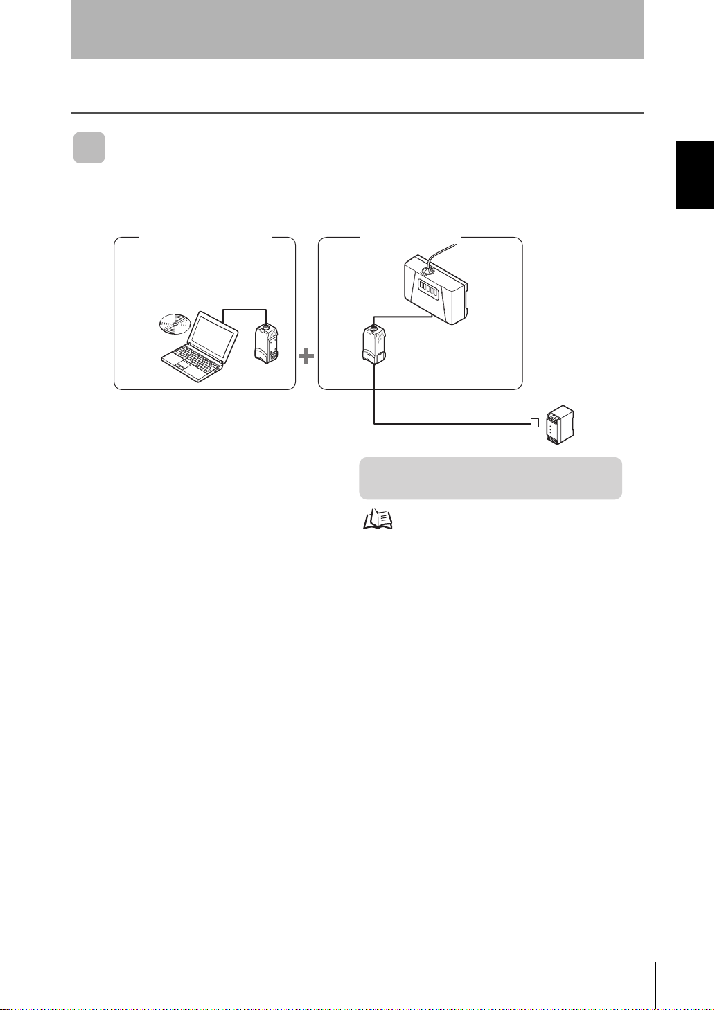
Direct Clean Sensing System
■ Data Logging
Clean Monitoring System
ZN-SFW11
Realtime
Clean Air Monitor
Interface
Unit
Z
N
S
F
1
1
Amplifier
Unit
Section 1 FEATURES
Air Particle Sensor
ensor
ZN-PD03
ZN-PDA11
DC power supply
[Features]
• Monitoring/Logging the Amount of Particles
System Manu al
7
ZN
Section 1
S
r
A
For details on settings, see p.18.
To extend the cable mentioned above, a
commercially available LAN connector (female to
female, straight type) and a LAN cable (straight
type: Category 5E or higher) must be used.
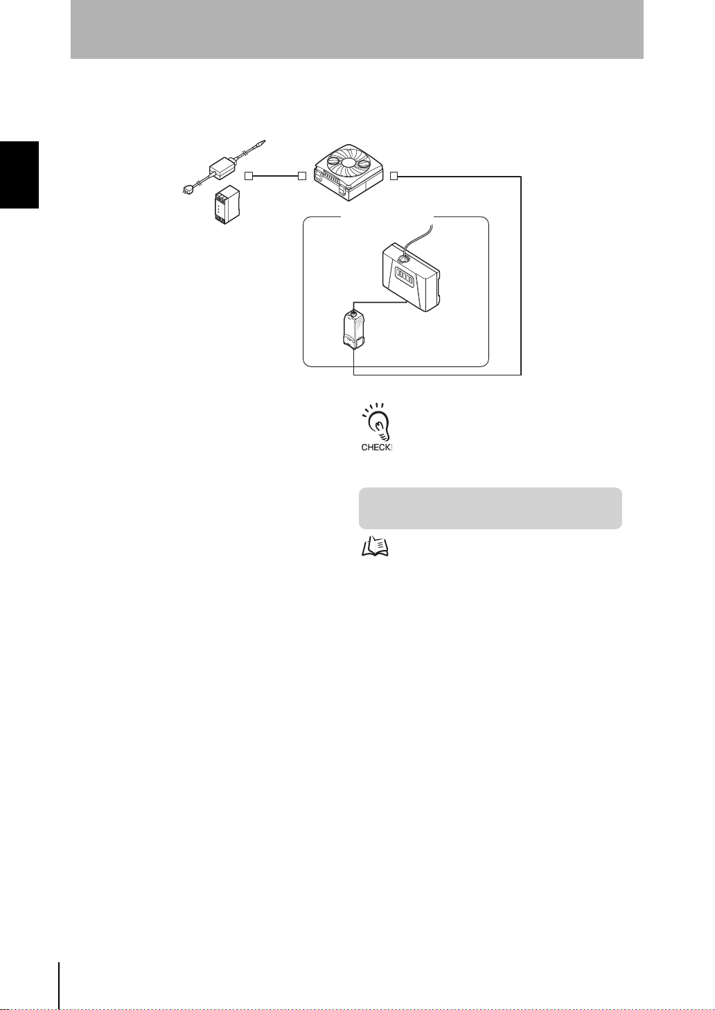
System Configuration Examples
■ Feedback
Section 1 FEATURES
C adapter (provided)
Or, DC power supply
Air Clean Unit
ZN-A2502
ZN-A4105
Air Particle Sensor
enso
Amplifier
Unit
ZN-PD03
ZN-PDA12
Cable length: standard 2 m
[Features]
• Feedback-based Automatic Adjustment of Air Volume
ZN
System Manu al
8
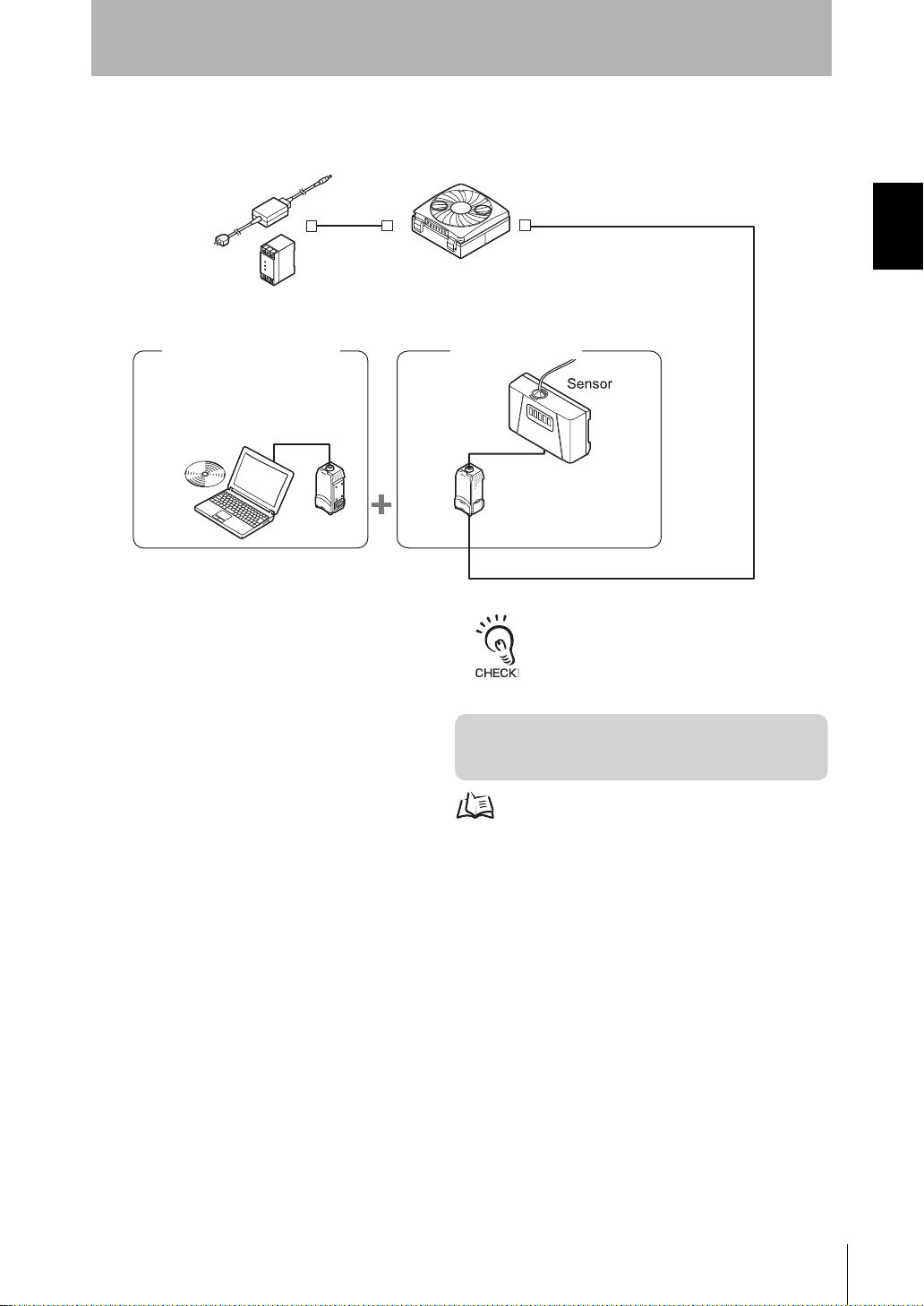
■ Feedback and Data Logging
Z
N
S
F
1
1
Air Clean Unit
ZN-A2502
ZN-A4105
[Features]
• Feedback-based Automatic Adjustment of Air Volume
• Monitoring/Logging the Amount of Particles
Air Particle Sensor
Interface
Unit
Realtime
Clean Air Monitor
ZN-PD03
Amplifier
Unit
ZN-PDA12
Clean Monitoring System
ZN-SFW11
AC adapter (provided)
Or, DC power supply
Cable length: standard 2 m
For details on settings, see p.18, p.25.
To extend the cable mentioned above, a
commercially available LAN connector (female to
female, straight type) and a LAN cable (straight
type: Category 5E or higher) must be used.
Section 1
System Configuration Examples
Section 1 FEATURES
System Manu al
ZN
9
Section 1
For details on settings, see p.18, p.25.
To extend the cable mentioned above, a commercially available LAN
connector (female to female, straight type) and a LAN cable (straight type:
Category 5E or higher) must be used.
System Configuration Examples
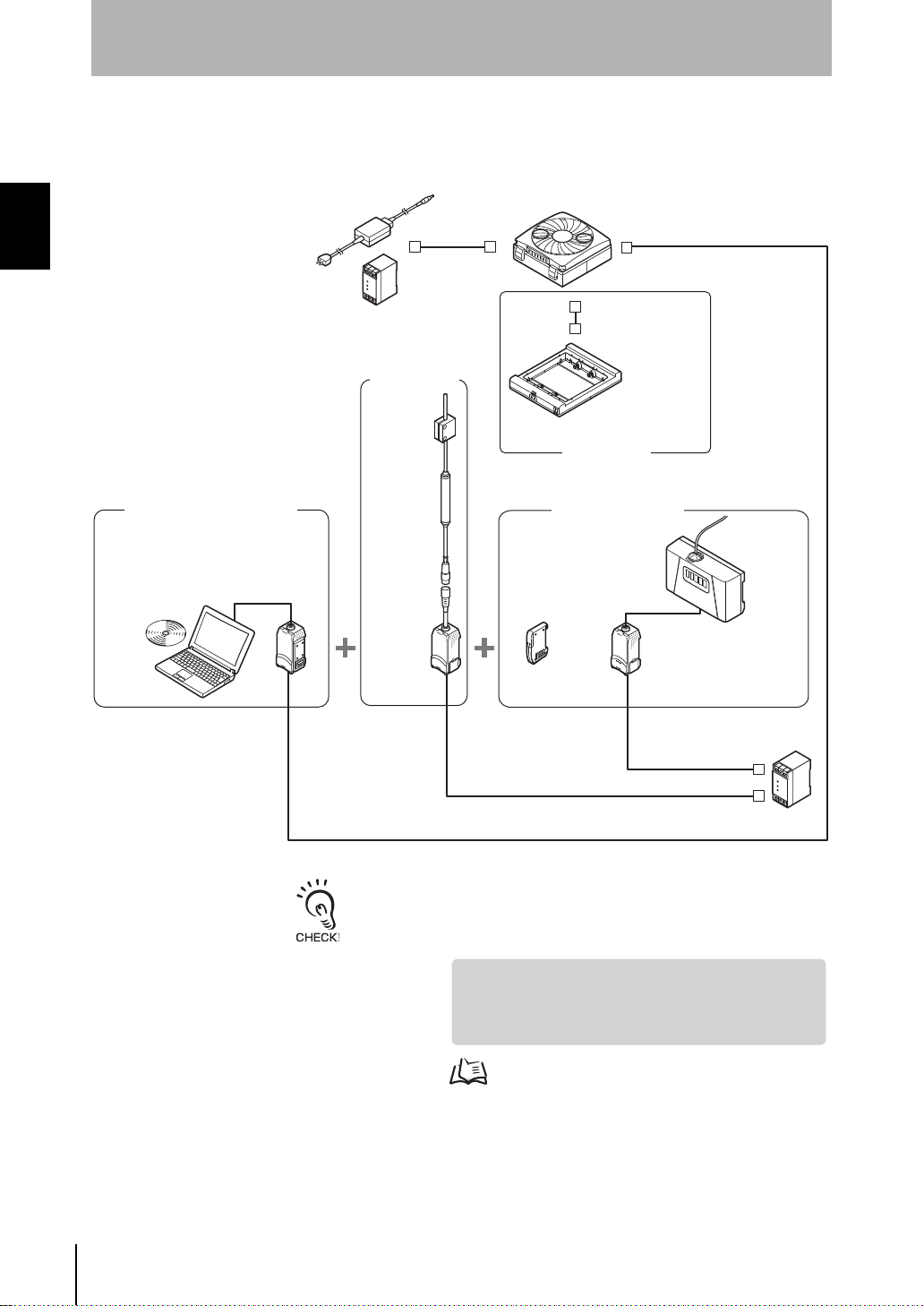
■ Dust Removal and Static Neutralization
Connection Example with Different Models (Electrostatic Sensor)
Section 1 FEATURES
Air Clean Unit
AC adapter (provided)
Or, DC power supply
ZN-A2502
ZN-A4105
Connector cable
(provided)
Clean Monitoring System
Realtime
Clean Air Monitor
Electrostatic
Sensor
ZJ-SD100
ZN-SFW12
Interface
Unit
OPE3
OPE2
OPE1
ZN
SF
1
2
Amplifier
Unit
ZJ-SDA11
Cable length: standard 2 m
Sensor
ZN-J25A
ZN-J41A
Ionizer Unit
Air Particle Sensor
Sensor
ZX-CAL2
Amplifier
Unit
ZN-PD03
ZN-PDA11
Calculating
Unit
OPE3
OPE2
OPE1
ZERO ENABLE
(kV)
Z
J
-S
D
A
1
1
DC power
supply
10
ZN
System Manu al
[Features]
• Simultaneous Monitoring of the Ion Balance
• Feedback-based Automatic Adjustment of Air Volume
• Monitoring/Logging the Amount of Particles
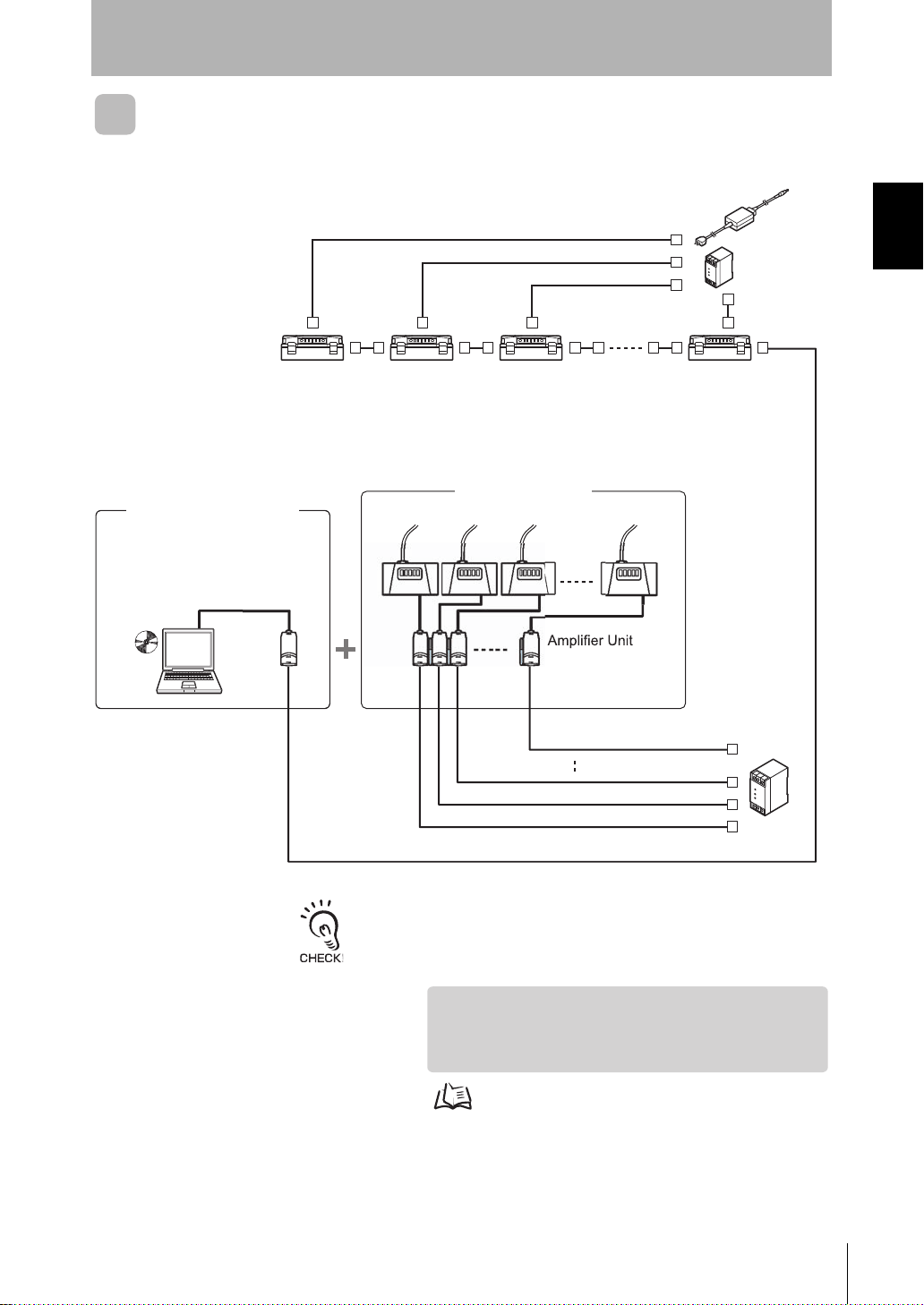
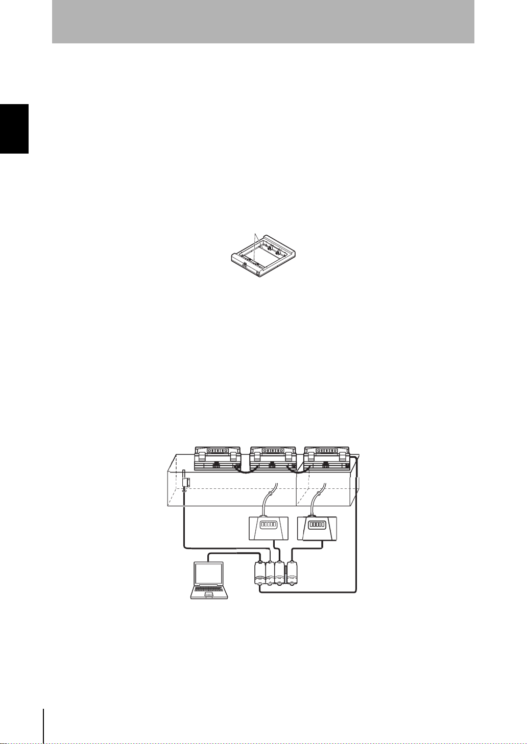
ZN-A2502
ZN-A4105
Air Clean Unit
Air Particle Sensor
Calculating Unit
ZX-CAL2
ZN-PD03
Sensor
ace
Unit
e
r
ZN-SFW12
Clean Monitoring System
Commercially available LAN cable
(straight type: Category 5E or higher)
DC power
supply
[Features]
• Feedback-based Automatic Adjustment of Air Volume
• Monitoring/Logging the Amount of Particles
• Detecting the Cleanliness of Multiple Processes
AC adapter
(provided)
Or,
DC power supply
Cable length: standard 2 m
For details on settings, see p.31.
To extend the cable mentioned above, a commercially available LAN
connector (female to female, straight type) and a LAN cable (straight type:
Category 5E or higher) must be used.
Realtim
Clean Air Monito
Multi-Clean Sensing System
Interf
Section 1
System Configuration Examples
Section 1 FEATURES
-
System Manu al
ZN
11

Section 1
System Configuration Examples
MEMO
Section 1 FEATURES
12
ZN
System Manu al
Section 2
UPGRADING THE SYSTEM
Before Upgrading the System 14
Flow of Operations for Upgrading the System 14
Installing the Exclusive Monitoring Software 15
Setup Methods Suited to Specific Applications 18
Automatically Adjusting the Air Volume Level 18
Monitoring/Logging the Amount of Particles 25
Detecting the Cleanliness of Multiple Processes 31
Section 2 UPGRADING THE SYSTEM
System Manu al
ZN
13
Section 2
p.18 p.25 p.31
p.48
Before Upgrading the System
Before Upgrading the System
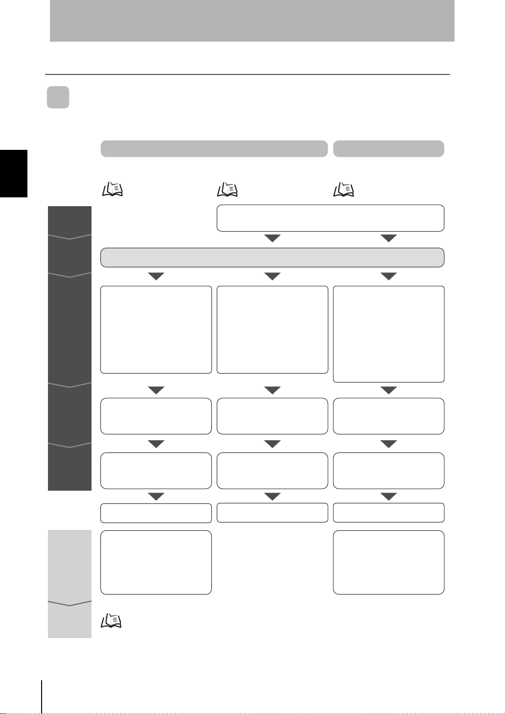
Flow of Operations for Upgrading the System
Section 2 UPGRADING THE SYSTEM
Preparation
Installation
Connections
Checks
Direct Clean Sensing System
Automatically Adjusting
the Air Volume Level
Refer to the Instruction Sheet packaged with each device.
• Setting the ID of the Air Clean
Unit
• Connecting the Air Clean Unit
and Air Particle Sensor
• Connecting the Air Clean Unit
power supply
Checking communications Checking system operation Checking system operation
Monitoring/Logging
the Amount of Particles
Installing the exclusive monitoring software
• Connecting the Air Particle
Sensor and Interface Unit
together
• Connecting the Interface Unit
and personal computer
• Connecting the Air Particle
Sensor power supply
Multi-Clean Sensing System
Detecting the Cleanliness of
Multiple Processes
• Setting the ID of the Air Clean Unit
• Connecting the Air Clean Unit
and Interface Unit
Connecting Air Clean Units to each other
•
• Connecting the Air Particle Sensor
and Interface Unit together
• Connecting the Interface Unit
and personal computer
• Connecting the Air Particle
Sensor power supply
Connecting the Air Clean Unit power supply
•
14
Operations
and settings
Resetting
during
operation
Maintenance
ZN
System Manu al
Setting the feedback conditions
Starting operation
• Resetting the feedback method
Resetting the target cleanliness class
•
• Resetting the feedback cycle
Resetting the low power air volume level
•
•
Resetting the high power air volume level
• Resetting the high power time
Trend graph display/data logging
Starting monitoring/logging Starting operation
Setting the feedback conditions
• Resetting the feedback method
Resetting the target cleanliness class
•
• Resetting the feedback cycle
Resetting the low power air volume level
•
• Resetting the calculation type
Resetting the high power air volume level
•
• Resetting the high power time

Section 2
Clean Monitoring System
(ZN-SFW11/SFW12)
Realtime
Clean Air Monitor
Interface Unit
Numerical display of measured
amount of particles
Graphic display of changes in
measured values over time
Logging of data
Display and setting of Air Particle Sensor and Interface Unit settings
Before Upgrading the System
Installing the Exclusive Monitoring Software
The Exclusive Monitoring Software (Realtime Clean Air Monitor) tool is provided for the
ZN Series. This tool allows you to set sensing functions, acquire and collect the amount
of measured particles, and display this information as a graph on a personal computer.
ZN-SF12
• Monitoring of measurement results
Section 2 UPGRADING THE SYSTEM
• Function setup support
■ Operating Environment
The following operating environment for Exclusive Monitoring Software is
recommended. Check the environment before installing the software.
Item Condition
OS Windows 2000/XP
CPU PentiumIII 850 MHz or faster (2 GHz or faster recommended)
RAM 128 MB or more (256 MB or more recommended)
Free space on hard disk At least 50 MB
Display screen 1024 x 768 dots
High Color (16-dot) or higher
• Windows is a trademark or registered trademark of Microsoft Corporation.
System Manu al
ZN
15
 Loading...