

Page 1

Cat. No. Z288-E1-01
ZG2 Series
Smart Sensor
2D Profi le Measuring Sensors
USERS MANUAL
Page 2

Page 3

Introduction
Thank you for purchasing the ZG2 series.
This manual provides information regarding functions, performance and operating methods that
are required for using the ZG2.
When using the ZG2, be sure to observe the following:
• The ZG2 must be operated by personnel knowledgeable in electrical engineering.
• To ensure correct use, please read this manual thoroughly to deepen your understanding of the
product.
• Please keep this manual in a safe place so that it can be referred to whenever necessary.
■ How to Switch the Display Language to English
Turn the power ON with the MENU key held down. This displays the display language selection
screen.
PLEASE SELECT
LANGUAGE
ENG JPN
The Controller will start up with the messages displayed in English when it is next started up.
Page 4

READ AND UNDERSTAND THIS
DOCUMENT(Please Read)
1
User’s Manual
BEFORE USE
BASIC OPERATIONS
FUNCTION SETTINGS
CONNECTION WITH EXTERNAL
DEVICES
MEASUREMENT BY GANGMOUNTED CONTROLLERS
APPENDICES
1
2
3
4
5
6
Smart Sensor
2D Profile Measuring Sensors
ZG2 Series
Page 5

READ AND UNDERSTAND THIS DOCUMENT
Please read and understand this document before using the products. Please consult
your OMRON representative if you have any questions or comments.
WARRANTY
OMRON’s exclusive warranty is that the products are free from defects in materials and
workmanship for a period of one year (or other period if specified) from date of sale by
OMRON.
OMRON MAKES NO WARRANTY OR REPRESENTATION, EXPRESS OR IMPLIED,
REGARDING NON-INFRINGEMENT, MERCHANTABILITY, OR FITNESS FOR
PARTICULAR PURPOSE OF THE PRODUCTS. ANY BUYER OR USER
ACKNOWLEDGES THAT THE BUYER OR USER ALONE HAS DETERMINED THAT
THE PRODUCTS WILL SUITABLY MEET T HE R EQU I RE MENT S OF T HE IR IN TE NDE D
USE. OMRON DISCLAIMS ALL OTHER WARRANTIES, EXPRESS OR IMPLIED.
LIMITATIONS OF LIABILITY
OMRON SHALL NOT BE RESPONSIBLE FOR SPECIAL, INDIRECT, OR
CONSEQUENTIAL DAMAGES, LOSS OF PROFITS OR COMMERCIAL LOSS IN ANY
WAY CONNEC TED WITH THE PRODUCTS, WHETHER SUCH CLAIM IS BASED ON
CONTRACT, WARRANTY, NEGLIGENCE, OR STRICT LIABILITY.
In no event shall responsibility of OMRON for any act exceed the individual price of the
product on which liability is asserted.
IN NO EVENT SHALL OMRON BE RESPONSIBLE FOR WARRANTY, REPAIR, OR
OTHER CLAIMS REGARDING THE PRODUCTS UNLESS OMRON’S ANALYSIS
CONFIRMS THAT THE PRODUCTS WERE PROPERLY HANDLED, STORED,
INSTALLED, AND MAINTAINED AND NOT SUBJECT TO CONTAMINAT ION, ABUSE,
MISUSE, OR INAPPROPRIATE MODIFICATION OR REPAIR.
SUITABILITY FOR USE
THE PRODUCTS CONTAINED IN THIS DOCUMENT ARE NOT SAFETY RATED. THEY
ARE NOT DESIGNED OR RATED FOR ENSURING SAFETY OF PERSONS, AND
SHOULD NOT BE RELIED UPON AS A SAFETY COMPONENT OR PROTECTIVE
DEVICE FOR SUCH PURPOSES.
Please refer to separate catalogs for OMRON’s safety rated products.
OMRON shall not be responsible for conformity with any standards, codes, or regulations
that apply to the combination of products in the customer’s application or use of the
product.
At the customer’s request, OMRON will provide applicable third party certification
documents identifying ratings and limitations of use that apply to the products. This
information by itself is not sufficient for a complete determinatio n of the suitability of the
products in combination with the end product, machine, system, or other application or use.
The following are some examples of applications for which particular attention must be
given. This is not intended to be an e xhausti ve li st of all possi ble use s of t he produc ts, nor
is it intended to imply that the uses listed may be suit able for the products:
• Outdoor use, uses involving potential chemical contamination or electrical interference,
or conditions or uses not described in this document.
2
ZG2 User’s Manual
Page 6

• Nuclear energy control systems, combustion systems, railroad systems, aviation
systems, medical equipment, amusement machines, vehicles, safety equipment, and
installations subject to separate industry or government regulations.
• Systems, machines, and equipment that could present a risk to life or property.
Please know and observe all prohibitions of use applicable to the products.
NEVER USE THE PRODUCTS FOR AN APPLICATION INVOLVING SERIOUS RISK TO
LIFE OR PROPERTY WITHOUT ENSURING THAT THE SYSTEM AS A WHOLE HAS
BEEN DESIGNED TO ADDRESS THE RISKS, AND THAT THE OMRON PRODUCT IS
PROPERLY RATED AND INSTALLED FOR THE INTENDED USE WITHIN THE
OVERALL EQUIPMENT OR SYSTEM.
PERFORMANCE DATA
Performance data given in this document is provided as a guide for the user in determin ing
suitability and does not constitute a warranty. It may represent the result of OMRON’s test
conditions, and the users must correlate it to actual application requirements. Actual
performance is subject to the OMRON Warranty and Limitations of Liability.
CHANGE IN SPECIFICATIONS
Product specifications and accessories may be changed at any time based on
improvements and other reasons.
It is our practice to change model numbers when published ratings or features are
changed, or when significant construction changes are made. However, some
specifications of the product may be changed without any notice. When in doubt, special
model numbers may be assigned to fix or establish key specifications for your application
on your request. Please consult with your OMRON representative at any time to confirm
actual specifications of purchased products.
DIMENSIONS AND WEIGHTS
Dimensions and weights are nominal and are not to be used for manufacturing purposes,
even when tolerances are shown.
ERRORS AND OMISSIONS
The information in this document has been carefully checked and is believed to be
accurate; however, no responsibility is assumed for clerical, typographical, or
proofreading errors, or omissions.
PROGRAMMABLE PRODUCTS
OMRON shall not be responsible for the user’s programming of a programmable product,
or any consequence thereof.
COPYRIGHT AND COPY PERMISSION
This document shall not be copied for sales or promotions wit hout permission.
This document is protected by copyright and is intended solely for use in conjunction with
the product. Please notify us before copying or reproducing this document in any manner,
for any other purpose. If copying or transmitting this document to another, please copy or
transmit it in its entirety.
ZG2 User’s Manual
3
Page 7

Meanings of Signal Words
The following signal words are used in this manual.
Indicates a potentially hazardous situation which, if not
avoided, will result in minor or moderate injury, or may result in
serious injury or death. Additionally there may be significant
property damage.
Meanings of Alert Symbols
The following alert symbols are used in this manual
Indicates general prohibitions for which there is no specific symbol.
Indicates the possibility of laser radiation.
Indicates prohibition when there is a risk of minor injury from electrical
shock or other source if the product is disassembled.
This product is not designed or rated for ensuring safety of persons.
Do not use it for such purposes.
Never look into the laser beam. Doing so continuously will result in
visual impairment.
Do not attempt to dismantle, pressurize, or i ncinerate the product. Doing
so may cause the laser beam to leak, resulting in the danger of visual
impairment.
4
ZG2 User’s Manual
Page 8

Precautions for Safe Use
The following points are important to ensure safety, so make sure that they are strictly
observed.
1. Installation Environment
• Do not use the product in environments where it can be exposed to inflammable/
explosive gas.
• To secure the safety of operation and maintenance, do not install the product close to
high-voltage devices and power devices.
• Install the product in such a way that its ventilation holes are not blocked.
2. Power Supply and Wiring
• The voltage and AC power supply must be within the rated range (DC 24 V ±10%).
• Reverse connection of the power supply is not allowed.
• Open-collector outputs should not be short-circuited.
• Use the power supply within the rated load.
• High-voltage lines and power lines must be wired separately from this product. Wiring
them together or placing in the same duct may cause induction, resulting in
malfunction or damage.
• Use the product within the power supply voltage specified by this manual.
• Use a DC power supply with safety measures against high-voltage spikes (safet y extra
low-voltage circuits on the secondary side).
3. Other
• Do not disassemble, repair, or modify the product.
• Dispose of this product as industrial waste.
• Connect the exclusive device (Sensor). The product might break down or malfunction
if you use a part not included in the exclusive products.
• Should you notice any abnormalities, immediately stop use, turn OFF the power
supply, and contact your OMRON representative.
ZG2 User’s Manual
5
Page 9

Precautions for Correct Use
Observe the following precautions to prevent failure to operate, malfunctions, or
undesirable effects on product performance.
1. Installation Site
Do not install this product in locations subjected to the following conditions:
• Ambient temperature outside the rating
• Rapid temperature fluctuations (causing condensation)
• Relative humidity outside the range of 35 to 85%
• Presence of corrosive or flammable gases
• Presence of dust, salt, or iron particles
• Direct vibration or shock
• Reflection of intense light (such as other laser beams or electric arc-welding
machines)
• Direct sunlight or near heaters
• Water, oil, or chemical fumes or spray
• Strong magnetic or electr ic field
2. Power Supply and Wiring
• When using a commercially available switching regulator, make sure that the FG
terminal is grounded.
• If surge currents are present in the power lines, connect surge absorbers that suit the
operating environment.
• Before turning ON the power after the product is connected, make sure that the power
supply voltage is correct, there are no incorrect connections (e.g. load short-circuit),
and the load current is appropriate. Incorrect wiring may result in breakdown of the
product.
• Before connecting/disconnecting devices, make sure that the Sensor/Controller is
turned OFF. The Sensor or Controller may break down if it is connected/disconnected
while the power is ON.
• Use the extension cable sold separately for extending the cable between the Sensor
and the Controller.
p.17
• Use only combinations of the Sensor and Controller specified in this manual.
• Before turning the Controller ON, connect the Sensor. If the Controller is turned ON
without the Sensor connected, the Controller’s screen will remain dark and messages
cannot be read.
3. Warming Up
After turning the power supply ON, allow the product to stand for at least 30 minutes
before use. The circuits are still unstable just after the power supply is turned ON, so
measurement values may fluctuate gradually.
6
ZG2 User’s Manual
Page 10

4. Maintenance and Inspection
Do not use thinner, benzene, acetone or kerosene to clean the Sensor and Controller. If
large dust particles adhere to the filter on the front of the Sensor, use a blower brush
(used to clean camera lenses) to blow them off. Do not use breath from your mouth to
blow the dust off. To remove dust particles from the Sensor, wipe gently with a soft cloth
(for cleaning lenses) moistened with a small amount of alcohol. Do not use excessive
force to wipe off dust particles. Scratches to the filter might cause error.
5. Measurement Target
The measurement target is a non-transparent object. The sensor cannot detect the
following types of objects accurately: materials with extremely small reflectances, objects
smaller than the beam diameter, objects with large curvatures, or objects tilted to a large
degree.
6. Effect of Peripheral Lighting
Do not install the Sensor in a place where strong light hits the laser emitter/receiver
section of the Sensor.
Also, if a measurement target has a shiny surface, the light from the lighting will be
reflected and a malfunction may occur. In such a case, prevent reflection by, for example,
covering the light to stop reflection.
p.27
7. Compatibility of Mesurement Data
Bank data or System data saved with existing ZG series cannot be processed by ZG2.
ZG2 User’s Manual
7
Page 11

Editor’s Note
Important
Note
■ Meaning of Symbols
Menu items that are displayed on the Controller’s LCD screen, and windows, dialog boxes
and other GUI elements displayed on the PC are indicated enclosed by brackets “[ ]”.
■ Visual Aids
Indicates points that are import ant to achiev e the full product perf ormance,
such as operational precautions.
Indicates application procedures.
Indicates pages where related information can be found.
8
ZG2 User’s Manual
Page 12

CONTENTS
1. BEFORE USE
ZG2 Series. . . . . . . . . . . . . . . . . . . . . . . . . . . . . . . . . . 16
System Configuration . . . . . . . . . . . . . . . . . . . . . . . . . . 16
Part Names and Functions . . . . . . . . . . . . . . . . . . . . . . 18
Basic Knowledge for Operation . . . . . . . . . . . . . . . . 21
Profile Screen . . . . . . . . . . . . . . . . . . . . . . . . . . . . . . . . 21
Precautions when designing a production line. . . . 22
Measurement Range in Height Direction and Resolution 22
Trigger Measurement/Continuous Measurement . . . . . 24
Mounting and Connecting Devices. . . . . . . . . . . . . . 27
Mounting the Sensor Head . . . . . . . . . . . . . . . . . . . . . . 27
Mounting the Controller. . . . . . . . . . . . . . . . . . . . . . . . . 39
Connecting Devices. . . . . . . . . . . . . . . . . . . . . . . . . . . . 49
Overview of Settings and Measurement. . . . . . . . . . 52
Operation Modes. . . . . . . . . . . . . . . . . . . . . . . . . . . . . . 52
Tasks and Bank Data . . . . . . . . . . . . . . . . . . . . . . . . . . 53
STD Menu and EXP Menu . . . . . . . . . . . . . . . . . . . . . . 55
Initializing Controller Settings . . . . . . . . . . . . . . . . . . . . 56
1
2. BASIC OPERATIONS
Flow of Basic Setup . . . . . . . . . . . . . . . . . . . . . . . . . . 58
Starting Measurement . . . . . . . . . . . . . . . . . . . . . . . . 66
Monitoring the Measurement Status . . . . . . . . . . . . . . . 66
Magnifying the Profile Display. . . . . . . . . . . . . . . . . . . . 67
Function Keys . . . . . . . . . . . . . . . . . . . . . . . . . . . . . . . . 68
ZG2 User’s Manual
9
Page 13

3. FUNCTION SETTINGS
Setting Measurement Conditions . . . . . . . . . . . . . . . 70
How to Select Measurement Items . . . . . . . . . . . . . . . . 70
Measuring Height . . . . . . . . . . . . . . . . . . . . . . . . . . . . . 72
Measuring Step . . . . . . . . . . . . . . . . . . . . . . . . . . . . . . . 74
Measuring Position and Width. . . . . . . . . . . . . . . . . . . . 77
Measuring Angle . . . . . . . . . . . . . . . . . . . . . . . . . . . . . . 79
Measuring Angle and Point of Intersection . . . . . . . . . . 80
Measuring Cross-sectional Area . . . . . . . . . . . . . . . . . . 82
Measuring Point of Inflection. . . . . . . . . . . . . . . . . . . . . 83
Calculating Measurement Values . . . . . . . . . . . . . . . . . 86
Deleting measurement items. . . . . . . . . . . . . . . . . . . . . 86
Customizing Measurement Conditions . . . . . . . . . . 87
Magnifying the Profile Display. . . . . . . . . . . . . . . . . . . . 87
Changing Measurement Positions. . . . . . . . . . . . . . . . . 88
Changing Measurement Points. . . . . . . . . . . . . . . . . . . 89
Changing the Edge Level and Edge Direction. . . . . . . . 90
Scaling of Measurement Values . . . . . . . . . . . . . . . . 91
Image Adjustment. . . . . . . . . . . . . . . . . . . . . . . . . . . . 96
Adjusting Sensitivity. . . . . . . . . . . . . . . . . . . . . . . . . . . . 96
Changing Sensitivity Adjustment Region. . . . . . . . . . . . 99
Adjusting Profiles. . . . . . . . . . . . . . . . . . . . . . . . . . . . . 100
Adjusting the background filtering level. . . . . . . . . . . . 104
Setting noise filtering . . . . . . . . . . . . . . . . . . . . . . . . . . 104
Setting the high-power mode (increasing the amount of
emitted light) . . . . . . . . . . . . . . . . . . . . . . . . . . . . . . . . 105
Adjusting received light gain . . . . . . . . . . . . . . . . . . . . 105
Position Correction . . . . . . . . . . . . . . . . . . . . . . . . . 106
Slope Correction . . . . . . . . . . . . . . . . . . . . . . . . . . . . . 107
Height/Position Correction. . . . . . . . . . . . . . . . . . . . . . 109
Adjusting the Output Conditions of the Measurement
Result. . . . . . . . . . . . . . . . . . . . . . . . . . . . . . . . . . . . . 111
Setting the Average Number of Measurements . . . . . 111
Setting Smoothing . . . . . . . . . . . . . . . . . . . . . . . . . . . . 111
Setting the Hold Function . . . . . . . . . . . . . . . . . . . . . . 112
Setting Zero Reset . . . . . . . . . . . . . . . . . . . . . . . . . . 114
Setting the Offset Value. . . . . . . . . . . . . . . . . . . . . . . . 114
10
ZG2 User’s Manual
Page 14

Executing Reference Zero Reset . . . . . . . . . . . . . . . . 115
Bank Settings . . . . . . . . . . . . . . . . . . . . . . . . . . . . . . 116
Bank Switching (change of device setup) . . . . . . . . . . 116
Copying Bank Data . . . . . . . . . . . . . . . . . . . . . . . . . . . 116
Clearing Bank Data . . . . . . . . . . . . . . . . . . . . . . . . . . . 117
System Settings . . . . . . . . . . . . . . . . . . . . . . . . . . . . 118
Setting the Sensor Head Installation Status . . . . . . . . 118
Sensor Head Inclination Correction. . . . . . . . . . . . . . . 118
Setting the CCD Mode. . . . . . . . . . . . . . . . . . . . . . . . . 121
Setting the Sensor Head Data Loading Method . . . . . 121
Setting the Number of Digits Past the Decimal Point . 122
Setting/Changing the ECO Display . . . . . . . . . . . . . . . 122
Displaying the Controller Information . . . . . . . . . . . . . 122
Setting/Changing the Display Language. . . . . . . . . . . 123
Setting the Icon Color . . . . . . . . . . . . . . . . . . . . . . . . . 123
Saving the Setup Data. . . . . . . . . . . . . . . . . . . . . . . . . 123
4. CONNECTION WITH EXTERNAL DEVICES
ZG2 User’s Manual
Output Data List . . . . . . . . . . . . . . . . . . . . . . . . . . . . 126
Using the Controller I/O Cable. . . . . . . . . . . . . . . . . 127
Wiring the Controller I/O Cable . . . . . . . . . . . . . . . . . . 127
Assignments and Functions of I/O Signal Wires. . . . . 128
I/O Circuit Diagrams . . . . . . . . . . . . . . . . . . . . . . . . . . 130
Analog Output Settings . . . . . . . . . . . . . . . . . . . . . . . . 132
Setting for Measurement by the TRIG Signal . . . . . . . 136
Setting for Switching Banks by the BANK Signal . . . . 136
Checking Signal Statuses . . . . . . . . . . . . . . . . . . . . . . 137
Setting the GATE Signal . . . . . . . . . . . . . . . . . . . . . . . 137
Using the Parallel Output Unit (sold separately). . 138
Connecting the Parallel Output Unit . . . . . . . . . . . . . . 138
Layout of Output Terminals. . . . . . . . . . . . . . . . . . . . . 138
Output Circuit. . . . . . . . . . . . . . . . . . . . . . . . . . . . . . . . 139
Output Format of Measurement Values . . . . . . . . . . . 140
Output Format of Judgment Results . . . . . . . . . . . . . . 141
Assignment of Terminal Block Output. . . . . . . . . . . . . 143
11
Page 15

Setting the Number of Digits Past
the Decimal Point . . . . . . . . . . . . . . . . . . . . . . . . . . . . 143
Setting GATE Signal at Parallel Output. . . . . . . . . . . . 143
I/O Timing Charts . . . . . . . . . . . . . . . . . . . . . . . . . . . 144
Serial Communication . . . . . . . . . . . . . . . . . . . . . . . 149
Using the Serial Interface . . . . . . . . . . . . . . . . . . . . . . 149
Connecting Peripheral and External Devices . . . . . . . 152
Serial Auto Output at Trigger Measurement . . . . . . . . 155
Setting Automatic Output. . . . . . . . . . . . . . . . . . . . . . . 155
Setting the RS-232C Communication Specifications . 156
Setting the Node No. . . . . . . . . . . . . . . . . . . . . . . . . . . 156
About Communication Commands . . . . . . . . . . . . . . . 157
Bank Control Commands . . . . . . . . . . . . . . . . . . . . . . 160
Measurement Control/Measurement Value Acquisition
Commands . . . . . . . . . . . . . . . . . . . . . . . . . . . . . . . . . 162
Setting Acquisition/Change Commands . . . . . . . . . . . 165
Backup/Restore Commands . . . . . . . . . . . . . . . . . . . . 168
Utility commands. . . . . . . . . . . . . . . . . . . . . . . . . . . . . 172
Parameter List . . . . . . . . . . . . . . . . . . . . . . . . . . . . . . . 176
Command Processing Time . . . . . . . . . . . . . . . . . . . . 181
5. MEASUREMENT BY GANG-MOUNTED CONTROLLERS
Mounting Order and Assignment of CH Numbers. 184
Setup Example . . . . . . . . . . . . . . . . . . . . . . . . . . . . . 185
Measuring Wide Measurement Targets . . . . . . . . . . . 185
Required Settings. . . . . . . . . . . . . . . . . . . . . . . . . . . 187
Setting Mutual Interference Prevention . . . . . . . . . . . . 187
Settings Common to Gang-mounted Controllers. . . . . 189
Calculations Performed on Measurement Values Obtained
on Multiple Channels. . . . . . . . . . . . . . . . . . . . . . . . . . 190
I/O . . . . . . . . . . . . . . . . . . . . . . . . . . . . . . . . . . . . . . . . 191
12
ZG2 User’s Manual
Page 16

6. APPENDICES
Specifications and External Dimensions . . . . . . . . 194
Sensor Head . . . . . . . . . . . . . . . . . . . . . . . . . . . . . . . . 194
Controller. . . . . . . . . . . . . . . . . . . . . . . . . . . . . . . . . . . 203
Accessories. . . . . . . . . . . . . . . . . . . . . . . . . . . . . . . . . 206
Error Messages and Corrective Actions . . . . . . . . 211
Troubleshooting . . . . . . . . . . . . . . . . . . . . . . . . . . . . 213
Menu List. . . . . . . . . . . . . . . . . . . . . . . . . . . . . . . . . . 216
List of Key Operations . . . . . . . . . . . . . . . . . . . . . . . 218
Laser Safety . . . . . . . . . . . . . . . . . . . . . . . . . . . . . . . 219
Classification . . . . . . . . . . . . . . . . . . . . . . . . . . . . . . . . 219
Label Replacement . . . . . . . . . . . . . . . . . . . . . . . . . . . 219
Requirements from Regulations and Standards . . 222
Summary of Requirements to Manufactures. . . . . . . . 222
Summary of Requirements to User. . . . . . . . . . . . . . . 226
Definitions of Laser Classification . . . . . . . . . . . . . . . . 229
Compliance with EC Directives. . . . . . . . . . . . . . . . 231
Updating the Firmware. . . . . . . . . . . . . . . . . . . . . . . 232
Index . . . . . . . . . . . . . . . . . . . . . . . . . . . . . . . . . . . . . 237
Revision History . . . . . . . . . . . . . . . . . . . . . . . . . . . . 240
ZG2 User’s Manual
13
Page 17

MEMO
14
ZG2 User’s Manual
Page 18

BEFORE USE
ZG2 Series 16
Basic Knowledge for Operation 21
Precautions when designing a production
line 22
Mounting and Connecting Devices 27
Overview of Settings and Measurement 52
1
BEFORE USE
Page 19

ZG2 Series
Sensor Head
Sensor Head
Controller Controller
ZG2 series
Up to two units
can be
gang-mounted.
ZG2-WDC11/WDC41
PC
Smart Monitor ZG2
(exclusive PC software)
ZG2-WDS70
ZG2-WDS22
ZG2-WDS8T
ZG2-WDS3VT
Detects the
measurement
target.
Performs
measurement
processing and
outputs the result.
Photoelectric sensor, etc.
A trigger signal is
input to control
measurement
timing.
Exclusive PC software allows complex
setups and verification of measurement
values to be performed with ease.
SmartMonitor ZG2 and USB cable are
ZG2-WDC_1A accessories.
Measurement by the ZG2 series can be started immediately merely by connecting the
model of Sensor Head suited to the application to the Controller. Also, the ZG2 series can
support various measurement applications by using it in combination with peripheral
devices.
System Configuration
16
ZG2 Series
ZG2 User’s Manual
Page 20
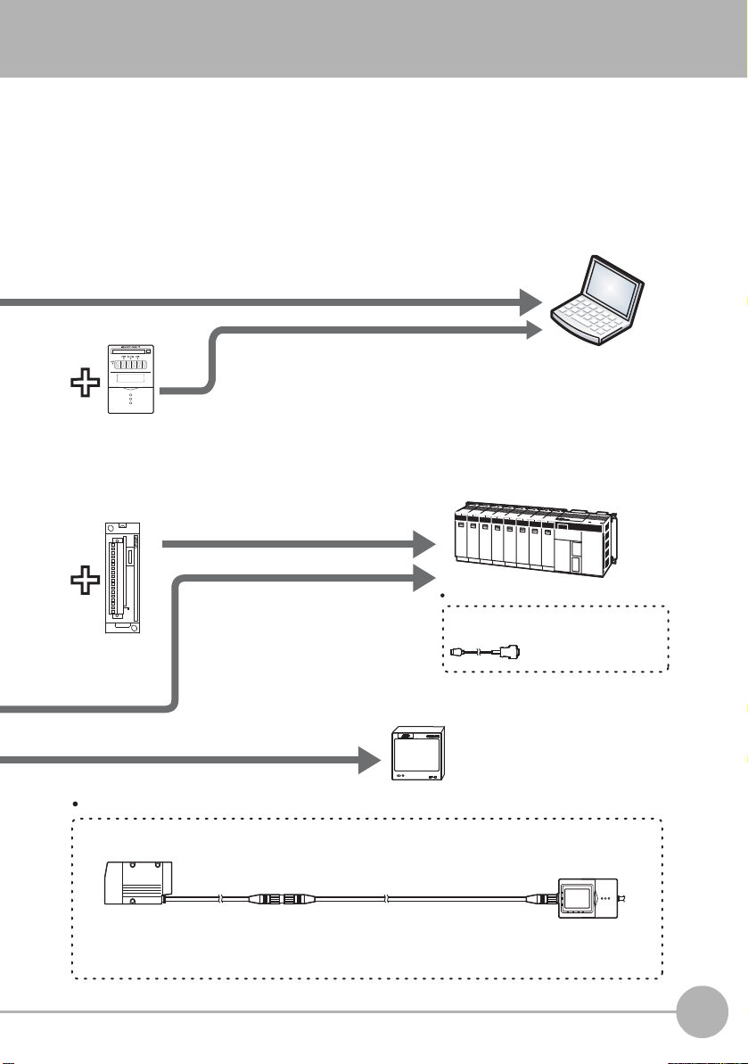
Sensor Head-Controller extension cable (option)
Extension cable
ZG2-XC_ _CR:
(3 m, 8 m, 15 m, 25 m) (flexible cable)
Cable for Sensor:
0.5 m, 2 m (flexible cable)
Exclusive extension cables are available for extending the installation distance between the
Sensor Head and the Controller.
ZG-RP D
PARALLEL OUTPUT UNIT
RS-23 2 C
DATA
PC
PLC
Graphic Data Controller ZP-C
Data Storage
Unit ZG2-DSU11
/DSU41
RS-232C connector cable (option)
For PC: ZS-XRS2
For PLC/PT: ZS-XPT2
Parallel Output
Unit ZG-RPD11
/RPD41
A USB connection allows measurement data to be
captured easily on a PC. Also, the Controller can be
controlled from a PC (e.g. switching/changing of setup
data and input of measurement trigger).
Measurement values and judgment
results can be output at high speed
on the parallel interface.
Measurement values and judgment
results can be acquired, and the
controller can be controlled (e.g.
setup data can be switched/changed
and measurement triggers can be
input).
The analog signals of measurement values can be displayed
as a waveform, and judgment results can be displayed in
color.
Measurement data can be collected and profiles
saved. Also, up to 4096 banks' (16 banks x 256 files)
of measurement conditions can be registered if the
number of banks on the Controller is insufficient. A
USB connection allows data to be captured on a PC.
For details, refer to the ZG2-DSU User's Manual.
Exclusive cables are available to match
the conn ected dev ice.
1
BEFORE USE
ZG2 User’s Manual
ZG2 Series
17
Page 21

Part Names and Functions
[ZG2-WDS3VT] [ZG2-WDS8T/WDS22] [ZG2-WDS70]
(1)
(3)
(2)
(4)
(1)
(3)
(2)
(4)
(3)
(2)
(1)
(4)
Sensor Head
Name Function
(1) Laser indicator These are laser beam warning indicators. The “standby indicator
(STANDBY)” indicates that the laser beam is ready for emission,
and the “laser energized indicator (LD ON)” indicates that the laser
is energized.
Both indicators are OFF until Controller startup is completed after
the power is turned ON.
Indicator At startup RUN/ADJ/FUN mode
LD OFF in
progress
Standby indicator
(STANDBY)
Laser indicator
(LD ON)
(2) Laser emitter This emits the laser for measurement.
(3) Laser receiver This receives the laser light reflected from the measurement target.
(4) Connector This is the connector for connecting to the Controller.
18
ZG2 Series
OFF ON ON
OFF OFF ON
LD ON in
progress
ZG2 User’s Manual
Page 22
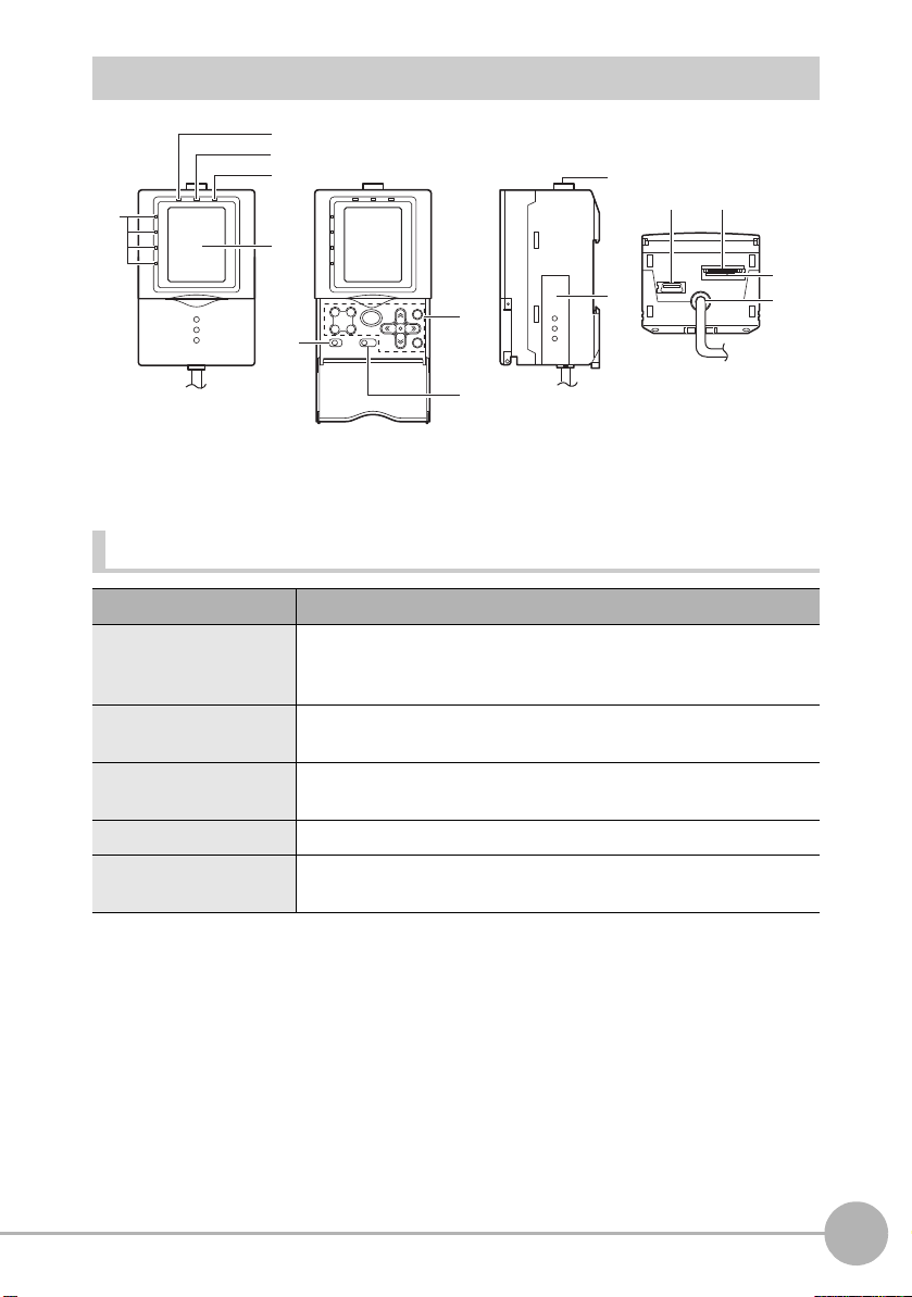
Controller
(2)
(3)
(4)
(1)
(5)
(1)
(3)
(2)
Display Operation Panel Connectors
(2)
(1)
(3)
(4)
(5)
(6)
Display
Name Function
(1)Judgment indicator The indicator turns ON when the result of task judgment is OK, and
turns OFF when a setting is not made, measurement is OFF, the
result of a judgment is NG, or an error occurs.
(2) Laser indicator The laser indicator turns ON while the Sensor Head is emitting a
laser beam.
(3) Zero Reset indicator The Zero Reset indicator turns ON when the zero reset function is
enabled.
(4) Trigger indicator The Trigger indicator turns ON when a trigger signal is input.
(5) LCD monitor The LCD monitor displays setup menus and images captured from
the Sensor Head.
1
BEFORE USE
ZG2 User’s Manual
ZG2 Series
19
Page 23
Operation Panel
Important
Name Function
(1) Control keys These keys are used for setting measurement conditions or
switching the display.
List of Key Operations p.218
(2) Mode switch This switch selects the operation mode.
FUN : Select this mode when setting measurement conditions.
Select this mode when adjusting the judgment threshold value.
ADJ :
RUN : Select this mode when performing measurement.
Measurement results and judgment results are output only when the
RUN mode is currently selected.
(3) Menu switch This switch selects the setup menu.
STD : Standard menu. Select this when setting the minimum
required items for measurement.
EXP : Expert menu. Select this when making a more detailed setup.
Connectors
Name Function
(1) Sensor Head
connector
(2) Function extension
connector
(3) USB port Connect the USB cable (MINI-B) to the USB port to connect to a
(4) RS-232C connector Connect the RS-232C cable (exclusive product) when you are
This connector connects the Sensor Head.
Insert this connector into the Controller Link Unit when gangmounting Data Storage Units and Controllers. Slide the cover
(supplied) downwards to open.
personal computer.
connecting the Controller to a PLC, programmable terminal or
personal computer.
20
RS-232C cable p.17
(5) Voltage/Current
switch
(6) I/O cable The I/O cable connects the Controller to the power supply and
ZG2 Series
This switch is for selecting voltage output or current output as the
analog output.
(default value: voltage output)
Before operating this switch, make sure that the Controller is turned
OFF.
external devices, such as timing sensors or programmable
controllers.
ZG2 User’s Manual
Page 24
Basic Knowledge for Operation
X-axis +X-axis -
Z-axis -
Z-axis +
NEAR
-5.00 mm
FAR
0
+5.00 mm
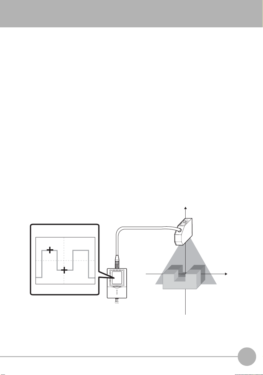
The ZG2 series is a non-destructive type sensor that measures cross-section shapes by
emitting a wide band of laser light onto the object and capturing light reflected from the
object by a CCD. This CCD imaging information is used to generate a profile of the
object’s shape, and dimensional shapes, such as height, steps, width, position, points of
intersection, inclination, and cross-sectional area, can be measured instantaneously from
the cross-section shape of the object.
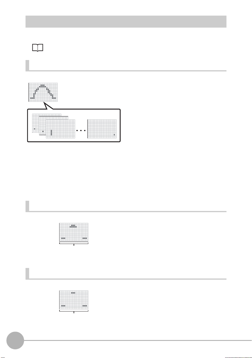
Profile Screen
A cross-section shape of the measurement object displayed on screen is called a
“profile.” Profiles are displayed on screen as a yellow line.
In the RUN/ADJ modes, the measurement state can be visually checked by these
profiles. Also, in the FUN mode, profiles can be used to set the measurement conditions.
Height measurement items are already set as the default, so it is possible to know
immediately the detection status of the Sensor Head by setting the operation mode to the
RUN mode.
On the ZG2 series, measurement points in the height and width directions are measured
on the vertical (Z-axis) and horizontal (X-axis) axes, respectively. Measurement values
are displayed as numerical values prefixed with a + (plus) or - (minus) sign depending on
the coordinate position.
1
BEFORE USE
ZG2 User’s Manual
Basic Knowledge for Operation
21
Page 25
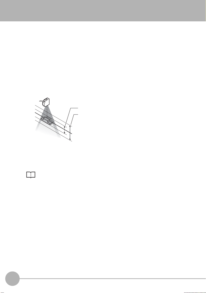
Precautions when designing a production line
Measurement range in high-speed mode
Measurement range in standard/high-resolution mode
Measurement center
The measurement center distance does not
change even if the CCD mode is changed.
The following describes details to be aware of before installing the ZG2 on a production
line.
Measurement Range in Height Direction and Resolution
The ZG2 incorporates the CCD mode function that alters how the CCD is used to achieve
high-speed and high-resolution measurement.
When the CCD mode is changed, the measurement range in the height direction and the
resolution are altered.
For actual details of measurement ranges, refer to the respective pages that explain
mounting of each of the sensor heads.
Mounting the Sensor Head p.27
22
Precautions when designing a production line
ZG2 User’s Manual
Page 26
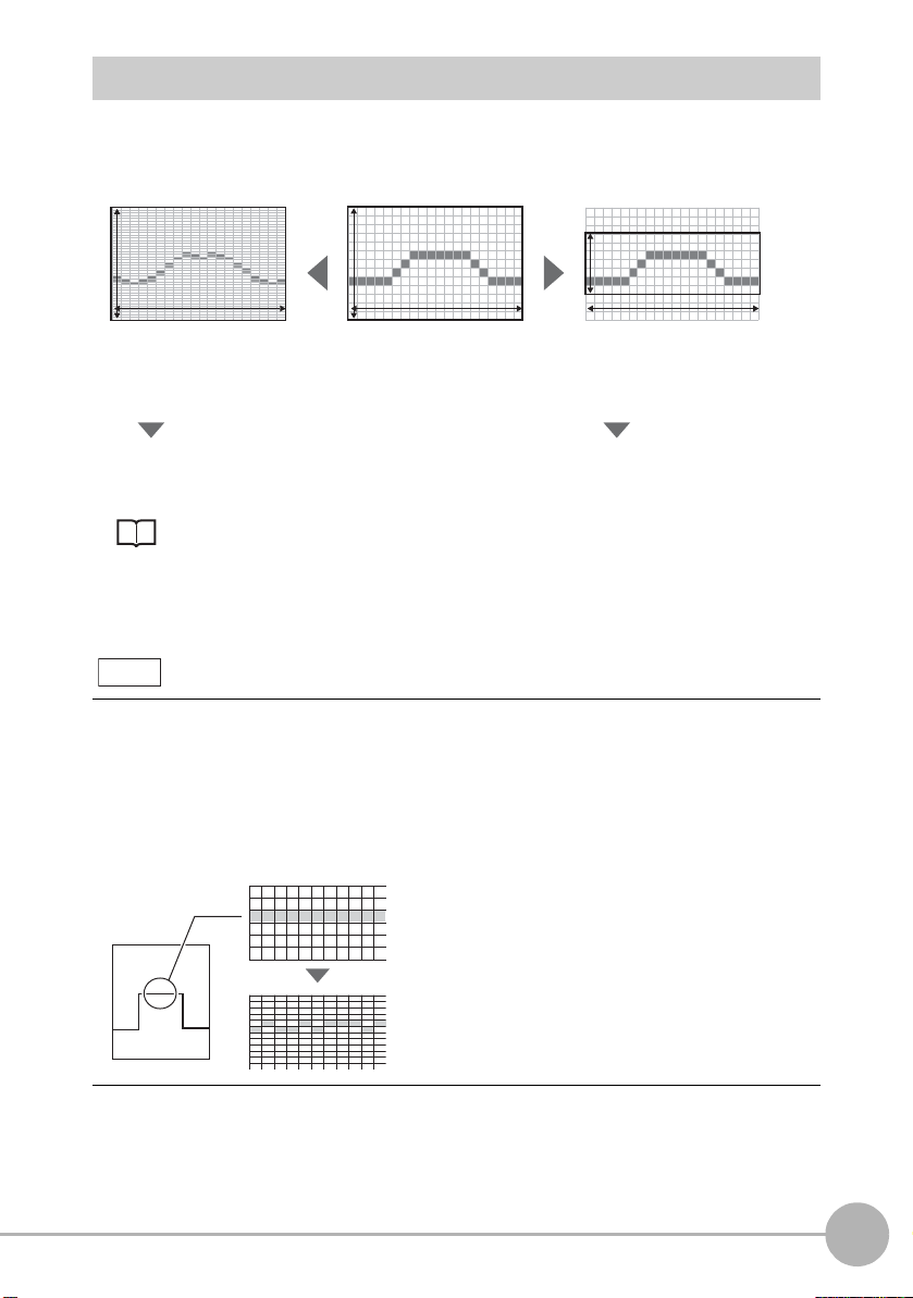
Three CCD Modes and Their Characteristics
High-resolution mode: min. 16 ms
400 pixels 100 pixels 50 pixels
Standard mode: min. 8 ms High-speed mode: min. 5 ms
631 pixels 631 pixels 631 pixels
By quadrupling the number of
pixels in the height direction
By decreasing the number of pixels
into 1/2 in the height direction
High-resolution measurement of
the shape of measurement targets
Shape measurement in fast line
speed processes
Standard images look flat.
Surfaces, in fact, are slightly uneven.
Resolution in the height direction changes as follows according to the CCD mode.
Setting the CCD Mode p.121
The resolution in the horizontal direction does not change. When measuring edge
position or width, select the CCD mode based on the response time as the resolution will
not change whichever mode is selected.
Note
Number of pixels and resolution
To express the clarity on a digital camera or image scanner, the term “resolution” is
used. The same approach is used on the ZG2 series, too. A “high resolution” expresses
a sharp image, while a “low resolution” expresses a grainy image. Resolution is
determined by the number of pixels per unit area. Though a sh arper or highe r re solut ion
image is obtained, the more pixels there are per unit area, processing takes that much
longer proportionate to the amount of information for that image.
1
BEFORE USE
ZG2 User’s Manual
Precautions when designing a production line
23
Page 27
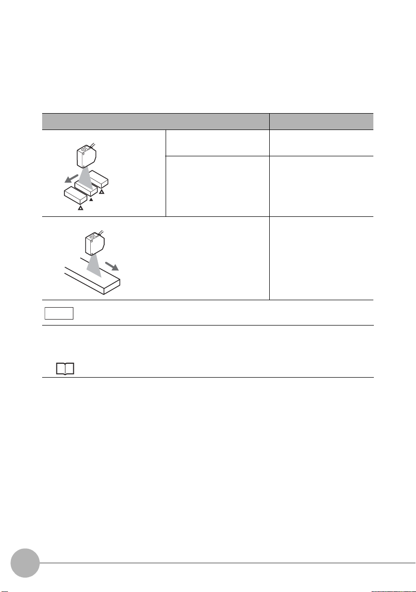
Trigger Measurement/Continuous Measurement
Trigger
Trigger
Trigger
The ZG2 series is provided with two measurement modes, “input of an external trigger to
start measurement” and “continuous measurement with out th e need for inp ut of a trigger.”
Note, however, that available sensitivities are restricted by the type of trigger and
direction in which the measurement object is moving. Select which combination to use to
suit your specific application.
Measurement trigger and direction in which object is flowing Appropriate sensitivity
Measurement by external trigger When object can be made
stationary
When object cannot be
made stationary
Continuous measurement AUTO sensitivity/FIXED
Note
High-speed MULTI
sensitivity/MULTI sensitivity
AUTO sensitivity/FIXED
sensitivity
sensitivity
The default setting is continuous measurement.
To perform measurement by an external trigger, the setting must be changed.
Setting for Measurement by the TRIG Signal p.136
24
Precautions when designing a production line
ZG2 User’s Manual
Page 28
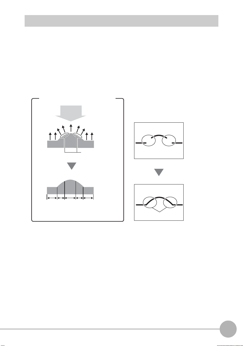
What is “Sensitivity Adjustment?”
In the case of a mountain-shaped
measurement object
Light emitted
from Sensor
Areas where
reflected light will
have difficulty
entering the CCD
High Low Medium Low High
Reference plane
Reflectance
The reflectance of the reference plane
differs from that of inclined surfaces.
Areas having low
reflectance cannot be
measured due to
insufficient light amount.
Sensitivity adjustment
Reproduction of profile
It is relatively easy to measure the shape of a measurement target that receives a
sufficient and uniform amount of light. However, in the case of measurement targets
having a complex shape, inclined surfaces cause reflected light to decrease and areas of
insufficient received light to occur. There are also cases where the amount of received
light is insufficient or, alternatively, saturated caused by the color or material of the
measurement target. In this way, the sensitivity of the Sensor must be adjusted so that
shapes are accurately captured even if the shape, color, material, etc. of the
measurement target is influenced.
1
BEFORE USE
ZG2 User’s Manual
Precautions when designing a production line
25
Page 29
Sensitivity Adjustment Functions of the ZG2 Series
The optimum sensitivity
is adjusted for individual
lines and combined to
form the image.
The optimum sensitivity
common to all lines is
adjusted.
Sensitivity is
fixed for all lines.
The ZG2 series is provided with three sensitivity adjustment functions.
Adjusting Sensitivity p.96
High-speed MULTI sensitivity/MULTI sensitivity
The amount of received light per individual
line is judged and the appropriate sensitivity
for each individual line is adjusted to
accommodate for all kinds of shape, color
and material. The measurement target must
be made stationary as time is required to
capture multiple image frames while
changing the sensitivity.
High-speed MULTI sensitivity is used when
MULTI sensitivity is required on lines having
a fast tact time. The upper/lower limit range at
which sensitivity is switched and the capture
count can be restricted. The optimum
sensitivity and number of image frames are
set automatically within this range. Note,
however, that the measurement must first be
made stationary even in the high-speed
MULTI sensitivity mode.
AUTO sensitivity
FIXED sensitivity
26
Precautions when designing a production line
The amount of received light for all lines is
judged to adjust to the appropriate s ensitivity
for the entire area. As sensitivity is batchadjusted for all lines, the response is not as
slow as that for MULTI sensitivity, so this
mode is a generally applicable mode.
In this mode, a predetermined sensitivity is
used. As sensitivity is not adjusted during
measurement, response is fast, making it
ideal for when a trigger is input at short
intervals to perform measurement.
ZG2 User’s Manual
Page 30
Mounting and Connecting Devices
Mounting the Sensor Head
Never look into the laser beam. Doing so continuously will result in
visual impairment.
Never look into the laser beam.
Do not attempt to dismantle, pressurize, or incinerate the p roduct. Doing so
may cause the laser beam to leak, resulting in the danger of visual
impairment. Do not attempt to dismantle, pressurize, or incinerate the product.
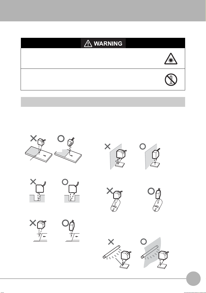
Installations to Suit Measur ement Target and Environment
Pay attention to the following points when mounting the Sensor Head to prevent
measurement precision from dropping.
Color/shiny surface boundary
Emission
axis
Boundary line
Narrow grooves or indentations
Reception
axis
Mounting near walls
Measurement errors can be reduced by installing the Sensor Head
with the line formed by the emission and reception axes parallel to
the wall, and painting the wall with non-reflective black paint.
Rotating objects
You can minimize the influence caused by vibration of the rotating object
and positional shifts by installing the Sensor Head with the line formed
by the emission and reception axes parallel to the axis of rotation.
1
BEFORE USE
Measuring stepped objects
ZG2 User’s Manual
Effect of peripheral lighting
Do not install the Sensor Head in a place where strong light hits the
laser emitter/receiver section of the Sensor. Also, if a measurement
target has a shiny surface, the light from the lighting will be reflected
and a malfunction may occur. In such as case, prevent reflection, for
example, by covering the light to stop reflection.
Mounting and Connecting Devices
27
Page 31
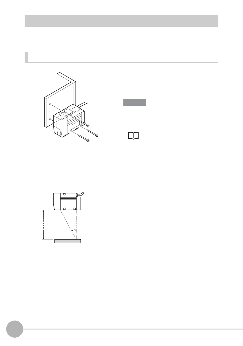
Mounting the ZG2-WDS70
Important
Mounting for diffuse reflection
measurement
Emission axis
Reception axis
210 mm
19°
Measurement target
Fix by mounting screws making sure that the distance between the Sensor Head and
measurement target is matched.
Mounting method
Fasten the Sensor Head onto the mounting
base with M4 screws.
Tightening torque: 1.2 N·m
For details on the positions of screw holes,
check the external dimensions in
“APPENDICES.”
External dimensions p.196
Mounting position
Mount the Sensor Head according to the following distances and angle.
28
Mounting and Connecting Devices
ZG2 User’s Manual
Page 32

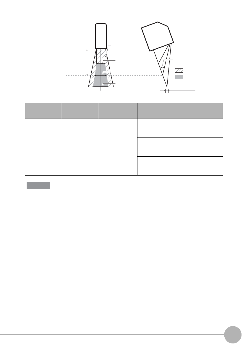
Measurement range
Important
Numerical values in the figure are for when the standard CCD mode is set. When the
CCD mode is changed, check the values in the table below.
<Mounting for diffuse reflection measurement>
1
BEFORE USE
Measurement center distance
NEAR end
CENTER
FAR end
210 mm
+30 mm
0 mm
-30 mm
CCD Mode Measurement
center distance
Standard
mode
Highresolution
mode
High-speed
mode
210mm ±30 mm NEAR end: 63mm 300 µm
Spread angle 10°
Measurement range (width)
63 mm
70 mm
79 mm
Measurement
range (height)
±48 mm NEAR end: 57mm 410 µm
±15 mm NEAR end: 66mm 210 µm
Measurement range
(width)
CENTER: 70mm 120 µm
FAR end: 79mm 300 µm
CENTER: 70mm 120 µm
FAR end: 83mm 410 µm
CENTER: 70mm 120 µm
FAR end: 74mm 210 µm
Angle of intersection 19°
: Irradiation range
: Measurement range
Beam diameter
Beam
diameter
The beam diameter and measurement range (width) between the NEAR/FAR ends are nominal
values, and are not to be used as guaranteed values.
ZG2 User’s Manual
Mounting and Connecting Devices
29
Page 33

Mounting the ZG2-WDS22
Important
Fix by mounting screws making sure that the distance between the Sensor Head and
measurement target is matched.
Mounting method
Fasten the Sensor Head onto the mounting
base with M4 screws.
Tightening torque: 1.2 N·m
For details on the positions of screw holes,
check the external dimensions in
“APPENDICES.”
External dimensions p.197
Mounting position
Mount the Sensor Head according to the following distances and angle.
30
12.5°
Emission axis Reception axis
100 mm
25°
Measurement target
Mounting for diffuse reflection
measurement
Emission axis Reception axis
94 mm
Measurement target
Mounting for regular reflection
measurement
Note
The default mounting state of the Sensor Head is for diffuse reflection measurement. To set
the Sensor Head for regular reflection measurement, change the Sensor Head mounting
setting.
Setting the Sensor Head Installation Status p.118
Mounting and Connecting Devices
ZG2 User’s Manual
Page 34

Measurement range
NEAR end
+12 mm
CENTER
0 mm
FAR end
-12 mm
Measurement center distance
100 mm
Spread angle 10°
Angle of intersection 25°
: Measurement range
: Irradiation range
20 mm
22 mm
24 mm
Measurement range (width)
Beam diameter
Important
Numerical values in the figure are for when the standard CCD mode is set. When the
CCD mode is changed, check the values in the table below.
<Mounting for diffuse reflection measurement>
1
BEFORE USE
CCD Mode Measurement
center distance
Standard mode/
high-resolution
mode
High-speed
mode
The beam diameter and measurement range (width) between the NEAR/FAR ends are nominal
values, and are not to be used as guaranteed values.
100mm ±12 mm NEAR end: 20mm 220 µm
Measurement
range (height)
±6 mm NEAR end: 21mm 140 µm
Measurement range
(width)
CENTER: 22mm 60 µm
FAR end: 24mm 220 µm
CENTER: 22mm 60 µm
FAR end: 23mm 140 µm
Beam
diameter
ZG2 User’s Manual
Mounting and Connecting Devices
31
Page 35

<Mounting for regular reflection measurement>
Important
Measurement center distance
94 mm
NEAR end
CENTER
FAR end
+10 mm
0 mm
-10 mm
CCD Mode Measurement
center distance
Standard mode/
94mm ±10 mm NEAR end: 20mm 220 µm
high-resolution
mode
Measurement range (width)
20 mm
22 mm
24 mm
Measurement
range (height)
Measurement range
(width)
CENTER: 22mm 60 µm
Angle of intersection 25°
: Irradiation range
: Measurement range
Beam diameter
Beam
diameter
FAR end: 24mm 220 µm
Spread angle 10°
High-speed
mode
±6 mm NEAR end: 21mm 140 µm
CENTER: 22mm 60 µm
FAR end: 23mm 140 µm
The beam diameter and measurement range (width) between the NEAR/FAR ends are nominal
values, and are not to be used as guaranteed values.
32
Mounting and Connecting Devices
ZG2 User’s Manual
Page 36

Mounting the ZG2-WDS8T
Important
Mounting for diffuse reflection
measurement
Emission axis Reception axis
50 mm
30°
Measurement target
Mounting for regular reflection
measurement
Emission axis Reception axis
44 mm
Measurement target
15°
Fix by mounting screws making sure that the distance between the Sensor Head and
measurement target is matched.
Mounting method
Fasten the Sensor Head onto the mounting
base with M4 screws.
Tightening torque: 1.2 N·m
For details on the positions of screw holes,
check the external dimensions in
“APPENDICES.”
External dimensions p.197
Mounting position
Mount the Sensor Head according to the following distances and angle.
1
BEFORE USE
Note
The default mounting state of the Sensor Head is for diffuse reflection measurement. To set
the Sensor Head for regular reflection measurement, change the Sensor Head mounting
setting.
Setting the Sensor Head Installation Status p.118
ZG2 User’s Manual
Mounting and Connecting Devices
33
Page 37

Measurement range
Important
Numerical values in the figure are for when the standard CCD mode is set. When the
CCD mode is changed, check the values in the table below.
<Mounting for diffuse reflection measurement>
Measurement center distance
50 mm
NEAR end
CENTER
FAR end
+3 mm
0 mm
-3 mm
CCD Mode Measurement
center distance
Standard mode/
50mm ±3 mm NEAR end: 7.9mm 120 µm
high-resolution
mode
Measurement range (width)
7.9 mm
8.0 mm
8.6 mm
Measurement
range (height)
Angle of intersection 30°
: Irradiation range
: Measurement range
Beam diameter
Measurement range
(width)
Beam
diameter
CENTER: 8.0mm 30 µm
FAR end: 8.6mm 120 µm
Spread angle 10°
High-speed
mode
±1.5 mm NEAR end: 7.7mm 110 µm
CENTER: 8.0mm 30 µm
FAR end: 8.3mm 110 µm
The beam diameter and measurement range (width) between the NEAR/FAR ends are nominal
values, and are not to be used as guaranteed values.
34
Mounting and Connecting Devices
ZG2 User’s Manual
Page 38
<Mounting for regular reflection measurement>
Important
Measurement center distance
NEAR end
CENTER
FAR end
44 mm
+2 mm
0 mm
-2 mm
Spread angle 10°
Measurement range (width)
7.9 mm
8.0 mm
8.6 mm
1
BEFORE USE
Angle of intersection 30°
: Irradiation range
: Measurement range
Beam diameter
CCD Mode Measurement
center distance
Standard mode/
high-resolution
mode
High-speed
mode
The beam diameter and measurement range (width) between the NEAR/FAR ends are nominal
values, and are not to be used as guaranteed values.
44mm ±2 mm NEAR end: 7.9mm 120 µm
Measurement
range (height)
±1 mm NEAR end: 7.9mm 105 µm
Measurement range
(width)
CENTER: 8.0mm 30 µm
FAR end: 8.6mm 120 µm
CENTER: 8.0mm 30 µm
FAR end: 8.1mm 105 µm
Beam
diameter
ZG2 User’s Manual
Mounting and Connecting Devices
35
Page 39

Mounting the ZG2-WDS3VT
Important
Reception axis
22.3 mm
Emission axis
Measurement target Measurement target
Mounting for
regular reflection measurement
Mounting for
diffuse reflection measurement
20°
Emission axis Reception axis
10.6 mm
40°
Note
Fix by mounting screws making sure that the distance between the Sensor Head and
measurement target is matched.
Mounting method
Fasten the Sensor Head onto the mounting
base with M4 screws.
Tightening torque: 1.2 N·m
For details on the positions of screw holes,
check the external dimensions in
“APPENDICES.”
External dimensions p.199
Mounting position
Mount the Sensor Head according to the following distances and angle.
The default mounting state of the Sensor Head is for regular reflection measurement. To set
the Sensor Head for diffuse reflection measurement, change the Sensor Head mounting
setting.
Setting the Sensor Head Installation Status p.118
36
Mounting and Connecting Devices
ZG2 User’s Manual
Page 40

Measurement range
2.9 mm
3.0 mm
3.1 mm
Measurement range
(width)
Angle of intersection 40°
: Measurement rang
: Irradiation range
Beam diameter
+0.5 mm
CENTER
FAR end
Measurement center distance
22.3 mm
NEAR end
0 mm
-0.5 mm
Important
Numerical values in the figure are for when the standard CCD mode is set. When the
CCD mode is changed, check the values in the table below.
<Mounting for regular reflection measurement>
1
BEFORE USE
CCD Mode Measurement
center distance
Standard mode/
high-resolution
mode
High-speed
mode
The beam diameter and measurement range (width) between the NEAR/FAR ends are nominal
values, and are not to be used as guaranteed values.
22.3mm ±0.5 mm NEAR end: 2.9mm 40 µm
Measurement
range (height)
±0.25 mm NEAR end: 2.95mm 33 µm
Measurement range
(width)
CENTER: 3.0mm 25 µm
FAR end: 3.1mm 40 µm
CENTER: 3.0mm 25 µm
FAR end: 3.05mm 33 µm
Beam
diameter
ZG2 User’s Manual
Mounting and Connecting Devices
37
Page 41

<Mounting for diffuse reflection measurement>
NEAR end
+0.4 mm
CENTER
0 mm
FAR end
-0.4 mm
Measurement center distance
10.6 mm
2.9 mm
3.0 mm
3.1 mm
Measurement range
(width)
Angle of intersectio
: Measuremen
: Irradiation ra
Beam diameter
Important
CCD Mode Measurement
center distance
Standard mode/
10.6mm ±0.4 mm NEAR end: 2.9mm 40 µm
high-resolution
mode
Measurement
range (height)
Measurement range
(width)
Beam
diameter
CENTER: 3.0mm 25 µm
FAR end: 3.1mm 40 µm
High-speed
mode
±0.2 mm NEAR end: 2.95mm 33 µm
CENTER: 3.0mm 25 µm
FAR end: 3.05mm 33 µm
The beam diameter and measurement range (width) between the NEAR/FAR ends are nominal
values, and are not to be used as guaranteed values.
38
Mounting and Connecting Devices
ZG2 User’s Manual
Page 42
Mounting the Controller
Important
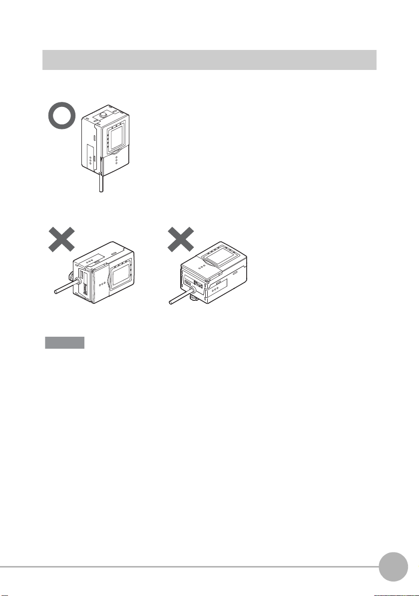
Cautions Regarding the Mounting Orientation
To improve heat radiation, install the Controller only in the orientation shown below.
Do not install the Controller in the following orientations:
1
BEFORE USE
• Do not block the ventilation holes at the top and bottom of the Controller body. Doing so will
cause heat to build up inside and result in a malfunction.
• When the temperature inside the control panel exceeds the ambient temperature of 50°C,
provide forced-air cooling or more space at surrounding areas, or improve air circulation to
lower the ambient temperature to 50°C or less.
ZG2 User’s Manual
Mounting and Connecting Devices
39
Page 43
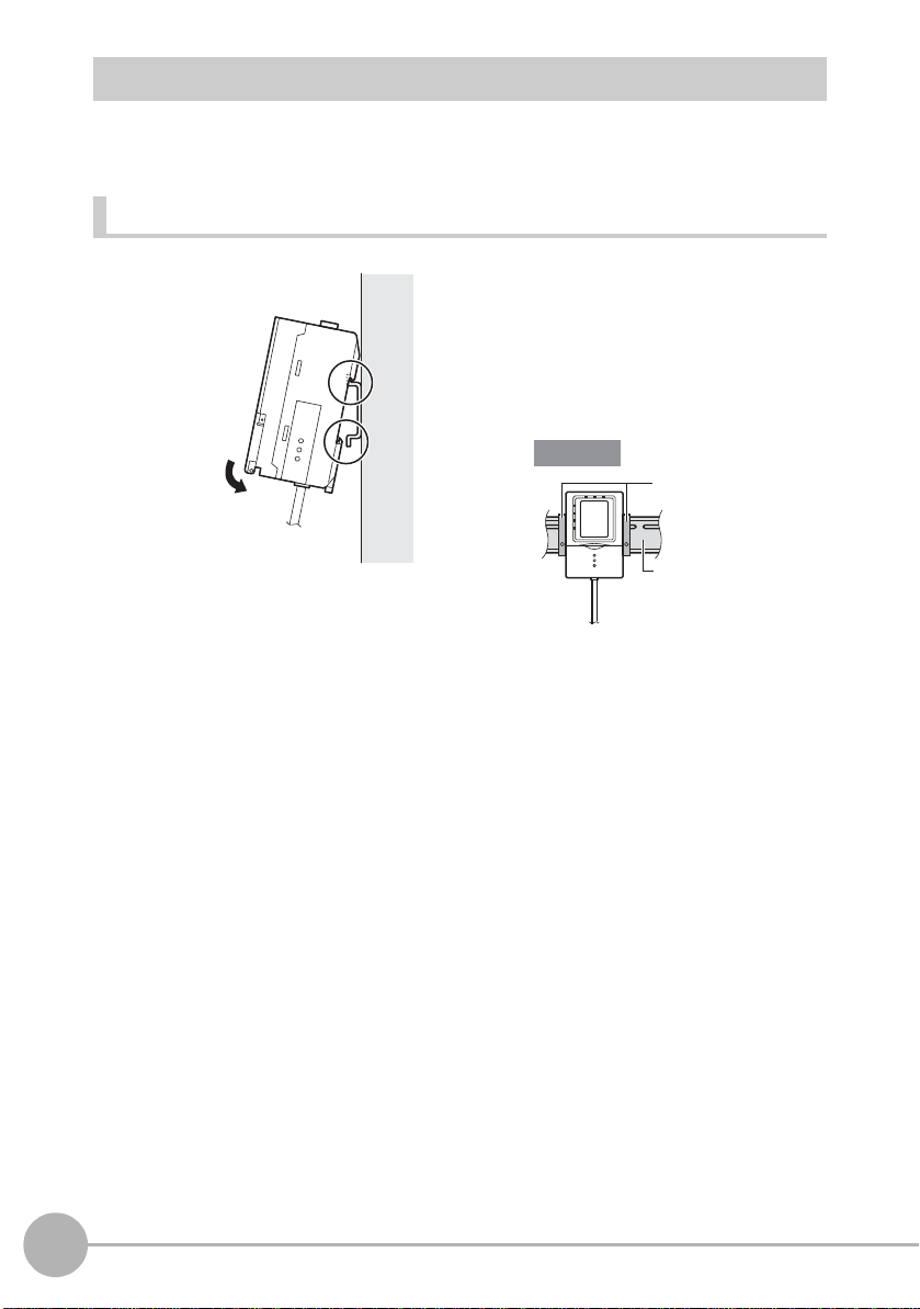
Mounting on a DIN Track
1
2
Important
DIN track (sold separately)
PFP-100N (1 m)
PFP-50N (0.5 m)
PFP-100N2 (1 m)
End plate
Mount Controllers on a DIN track correctly according to the number of Controllers to be
used.
When using only one Controller
1 Hook the connector end of the
Controller onto the DIN track.
2 Push the Controller down onto
the DIN track until the hook on the
I/O cable side is locked.
After mounting the Controller on the
DIN track, attach the end plates on
both sides of the Controller.
40
Mounting and Connecting Devices
ZG2 User’s Manual
Page 44

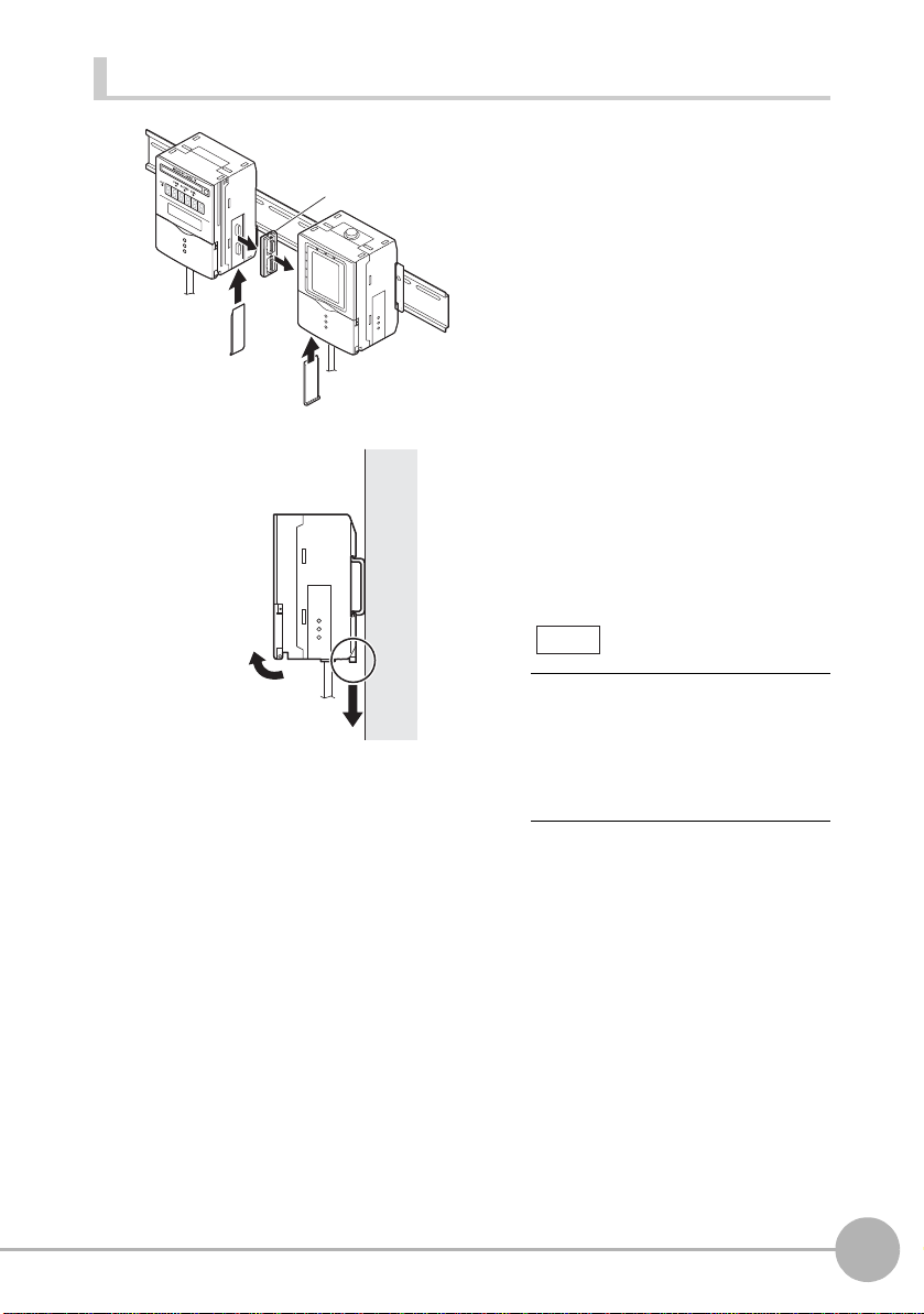
When gang-mounting devices
1
2
4
5
Controller
Link Unit
(sold separately)
Important
Indentation
The following explains how to mount Controllers when using a Data Storage Unit as well
or when gang-mounting two Controllers on the DIN track.
1 Hook the connector end of the
Controller onto the DIN track.
2 Push the Controller down onto
the DIN track until the hook on the
I/O cable side is locked.
3 Open the gang-mount cover.
Slide the cover downwards to
remove.
4 Insert the Controller Link Unit into
4
5
3
3
the connector on the unit on the
left side.
1
BEFORE USE
ZG2 User’s Manual
The connector must be inserted at the
correct orientation. Insert so that the
indentation on the Controller Link Unit
in the figure above matches the
connector protrusion on the unit on the
left side.
Mounting and Connecting Devices
41
Page 45

5 Slide the Controller on the right
Note
Important
DIN track (sold separately)
PFP-100N (1m)
PFP-50N (0.5m)
PFP-100N2 (1m)
End plate
1
2
side towards the Controller Link
Unit so that it fits into the
Controller Link Unit.
The mounting method is the same
even when two Controllers are gangmounted onto the Data Storage Unit.
Mount in the following order: Data
Storage Unit → 1st Controller → 2nd
Controller.
Attach the end plates on both sides of
the Controller.
Removing the Controller from the DIN track (when using only one Controller)
42
Mounting and Connecting Devices
1 Pull the hook on the I/O cable end
of the Controller downwards.
2 Lift up the Controller from the I/O
cable end, and remove it from the
DIN track.
ZG2 User’s Manual
Page 46
Removing Controllers from the DIN track (when gang-mounting devices)
1
2
3
3
Controller
Link Unit
(sold separately)
4
5
Note
1 Slide the Controller so that it is
removed from the connector on
the Controller Link Unit.
1
BEFORE USE
2 Remove the Controller Link Unit
2
1
from the connector on the Data
Storage Unit.
3 Attach the covers to the Data
3
3
Storage Unit and Controller g ang mount.
4 Pull the hook on the I/O cable end
of the Controller downwards.
5 Lift up the Controller from the I/O
cable end, and remove it from the
DIN track.
The removal method is the same
even when two Controllers are gangmounted onto the Data Storage Unit.
Remove in the following order: 2nd
Controller → 1st Contro ller → Data
Storage Unit.
ZG2 User’s Manual
Mounting and Connecting Devices
43
Page 47
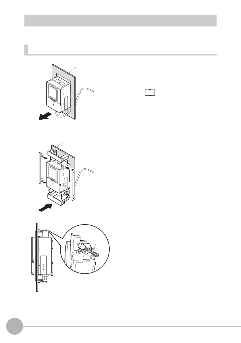
Mounting on a Panel
Panel
1
5
Mounting
bracket
Mount Controllers on a panel correctl y according to the number of Control lers t o be used.
When using only one Controller
1 Push out the Controller from the
rear of the panel towards the
front.
When mounting on a panel
p.206
Panel mount adapter
4
2 Install the short Panel Mount
2
Adapters on the four holes on the
Controller.
3 Install the long Panel Mount
Adapters on the two holes on the
Controller.
4 Install the Controller with Mount
3
Adapters attached onto the panel
from the front.
5 Hook the hooks of the mounting
fixture onto the two holes of the
short Mount Adapters and tighten
the screws.
6 Make sure that the Controller is
firmly fixed on the panel.
44
Mounting and Connecting Devices
ZG2 User’s Manual
Page 48

When gang-mounting devices
Important
H
L
D
O
N
Z
E
R
O
E
N
A
B
L
E
P
L
H
L
D
O
N
Z
E
R
O
E
N
A
B
L
E
P
L
H
L
D
O
N
Z
E
R
O
E
N
A
B
L
E
P
L
H
L
D
O
N
Z
E
R
O
E
N
A
B
L
E
P
L
2
Panel
H
L
D
O
N
Z
E
R
O
E
N
A
B
L
E
P
L
H
L
D
O
N
Z
E
R
O
E
N
A
B
L
E
P
L
H
L
D
O
N
Z
E
R
O
E
N
A
B
L
E
P
L
H
L
D
O
N
Z
E
R
O
E
N
A
B
L
E
P
L
3
Panel
mount
adapters
Panel mount
adapters
Important
1 Mount the Data Storage Unit and
Controllers onto the DIN track.
When gang-mounting
devices p.41
When mounting devices on a panel,
too, be sure to install the DIN track on
the rear side of the devices.
2 Push out the Data Storage Unit
and Controllers from the rear of
the panel towards the front.
3 Install the short Panel Mount
Adapters on the four holes on the
Data Storage Unit and
Controllers.
1
BEFORE USE
ZG2 User’s Manual
Install the short Panel Mount Adapters
on the gang-mounted Data Storage
Unit and all Controllers.
Mounting and Connecting Devices
45
Page 49

4 Install the long Panel Mount
H
LD ON ZERO
ENABLE
P
L
H
LD ON ZERO
ENABLE
P
L
H
LD ON
ZERO
ENABLE
P
L
H
LD ON
ZERO
ENABLE
P
L
4
Panel mount adapters
Panel mount adapters
Important
Panel
Important
Mounting
bracket
Important
Adapters on the two holes on the
short Panel Mount Adapter.
Attach the long Panel Mount Adapters
on only both sides of the gangmounted Data Storage Unit and
Controllers.
5 Install the Data Storage Unit and
Controllers with Mount Adapters
attached onto the panel from the
H
H
LD
LD
O
O
N
N
ZE
ZE
P
P
R
R
O
O
E
E
N
N
A
A
B
B
LE
LE
L
L
H
H
L
L
D
D
O
O
N
N
Z
Z
E
E
P
P
R
R
O
O
EN
EN
A
A
B
B
L
L
L
L
E
E
5
front.
Take care not to nip the I/O cable.
46
Mounting and Connecting Devices
6 Hook the hooks of the mounting
fixtures onto the two holes of the
short Mount Adapters and tighten
6
the screws.
Attach fixtures at two locations of each
of the gang-mounted Data Storage
Unit and all Controllers.
7 Make sure that the Data Storage
Unit and Controllers are firmly
fixed on the panel.
ZG2 User’s Manual
Page 50

Combinations of Gang-mounted Controllers
Important
OUTPUT
RUN
OUTPUT
RUN
OUTPUT
RUN
LD ON ZERO ENABLE
OUTPUT
RUN
ZG2-WDCZG2-WDC
ZG2-WDC ZG2-WDCZG2-DSU
ZG2-WDCZG2-DSU
With the ZG2 series, one Data Storage Unit (ZG2-DSU) and up to two Controllers (ZG2WDC) can be gang-mounted. For details on the Data Storage Unit (ZG2-DSU), refer to
the ZG2-DSU User’s Manual.
• Supply power to all of the gang-mounted Controllers.
• The following three gang-mount combinations and arrangements are allowed. Note that
other combinations and arrangements will not result in proper operation.
1
BEFORE USE
ZG2 User’s Manual
Mounting and Connecting Devices
47
Page 51

CH number when Controllers are gang-mounted
Data Storage
Unit
CH0 CH1 CH2
Controller
(fixed)
Important
CH1 CH2
CH numbers are automatically assigned as follows when Controllers are gang-mounted.
To collect data from a Controller using the Data Storage Unit (ZG2-DSU_1), select the
CH number of the targeted Controller.
LD ON ZERO ENABLE
OUTPUT
RUN
• In the gang-mounted arrangement, the Data Storage Unit must be located at the leftmost
end viewed from the front.
• Even wh en the Data Storage Unit is not gang-mounted, the CH numbers of the Controllers
are CH1 and CH2 in this order from the left.
LD ON ZERO ENABLE
OUTPUT
RUN
48
Mounting and Connecting Devices
ZG2 User’s Manual
Page 52

Connecting Devices
1
1
2
3
Important
Important
Ferrite coreFerrite core
Ferrite core
Before connecting/disconnecting the Sensor
Head, make sure that the Controller is turned
OFF. The Controller may break down if the
Sensor Head is connected or disconnected
while the power is ON.
1 Attach the ferrite cores (supplied)
to both ends of the Sensor cable.
2 Insert the Sensor Head connector
into the Controller until it locks in
place.
3 Connect the Controller’s I/O cable
and power supply.
If the Controller is turned ON without the Sensor Head connected, the Controller ’s screen will
remain dark and messages cannot be read. Before turning the Controller ON, connect the
Sensor Head.
Attaching the Ferrite Cores
Attach the ferrite cores (supplied) to both ends of the Sensor Head cable and to the
Controller’s I/O cable.
1
BEFORE USE
ZG2 User’s Manual
Mounting and Connecting Devices
49
Page 53

Connecting Cables
Important
1 Insert the Sensor Head’s
connector straight into the
Sensor Head connector on the
Controller.
Make sure that you hear the
connector snap firmly into place
when it is connected.
2 Fasten firmly with the fastening
screws (two screws, one each on
the left and right).
• Do not touch the terminals inside the connector.
• All settings on the Controller will be cleared if the Sensor Head is replaced with a different
type.
• Fasten the connector while making sure that it is not subjected to vibration or shock.
• Do not mount the Controller in such a way that a load is steadily applied on the connector, for
example, with tension applied to the cables.
50
When wiring, do not bend the cable for at least
10 mm from the edge of the connector.
At least 10 mm
Mounting and Connecting Devices
If the cable is bent in the first 10 mm away from
the edge of the connector, stress may adversely
affect measurements.
10 mm or less
ZG2 User’s Manual
Page 54

<Removing the cable>
ZG2-XC3CR: 3 m
ZG2-XC8CR: 8 m
ZG2-XC15CR: 15 m
ZG2-XC25CR: 25 m
Extension cable Cable for Sensor
(flexible cable): 0.5 m, 2 m
(Flexible cable)
Important
Loosen the fastening screws (two locations) to unlock the cable, and then draw out the
connector straight from the Sensor side.
Note
The cable connection between the Sensor Head and the Controller can be extended by using
the extension cable (sold separately). Attach the ferrite cores (supplied) to both ends of the
extension cable.
To extend the connection between the Sensor Head and the Controller
Connecting the Power Supply
1 Connect the power wire (brown)
and GND wire (blue) of the
Controller’s I/O cable to the 24
VDC (
±10%) power supply.
1
BEFORE USE
After turning the power supply ON, allow the product to stand for at least 30 minutes before
use. The circuits are still unstable just after the power supply is turned ON, so measurement
values may fluctuate gradually.
ZG2 User’s Manual
Note
The following power supply is
recommended:
• S8VS-03024 (24V DC, 1.3 A)
Be sure to connect the Controller to the
power supply in a 1:1 connection.
Mounting and Connecting Devices
51
Page 55

Overview of Settings and Measurement
ADJ mode
RUN mode
FUN mode
MEAS
FUN
Top Screen
Top Screen
109.052 10 mm
LV: 1-320
HEIGHT1 B01T1
Top Screen
Operation Modes
The ZG2-WDC has the following three
operation modes. Switch to the desired
mode before you start operation.
To switch the operation mode, use the mode
switch.
Mode Description
FUN mode This mode is for setting the measurement
conditions.
The easy-to-follow icon-based display
allows operations to be performed
intuitively.
52
ADJ mode This mode is for checking the
measurement state, and setting
threshold values and output conditions.
RUN mode This mode is used for performing actual
measurement. The measurement
information is displayed on the LCD
screen.
Overview of Settings and Measurement
HEIGHT1 B01T1
109.052 10 mm
LV: 1-320
ZG2 User’s Manual
Page 56

Tasks and Bank Data
(Task 1)
Height
Width
Step
(Task 2)
(Task 3)
(Task 4)
Crosssectional area
Bank 1
Setting for
product class A
Bank 2
For product class B
Bank 3
For product class C
Bank 4
For product class D
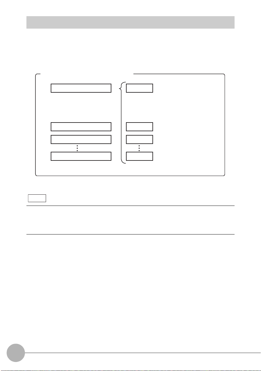
Multi-task Measurement
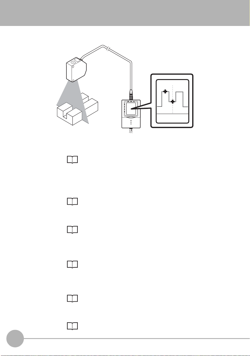
On the ZG2 series, up to eight measurements for a single profile can be processed
simultaneously. This function is called “multi-task measurement.”
Example:
Measurement is performed with “height,”
“width,” “step” and “cross-sectional area” set
to tasks 1 to 4, respectively. In other words,
this means that the total of tas ks 1 to 4 allow
you to judge the shape.
Data for Change of Device Setup
If you register bank data for each individual model, you can reduce the time required for
changing the device setup as all you need to do is to select different bank data to change
the measurement conditions.
1
BEFORE USE
ZG2 User’s Manual
Overview of Settings and Measurement
53
Page 57
Relationship between Tasks and Bank Data
You can register up to eight tasks to a single set of bank data. Up to 16 sets of bank data
can be set and saved on the ZG2 series, so you can prepare up to 128 measurement
patterns by combining bank data with task settings. Combinations of bank data and tasks
become the measurement and judgment condition settings.
Measurement/judgment conditions
Bank 1
• Profile registration information
• Setup information of image
adjustment function
•
Setup information of filter conditions
Bank 2
Bank 3
Bank 16
168x
Note
The maximum number of banks that can be saved on a Controller is 16. This can be
expanded up to 4096 banks (16 banks × 256 files) by gang-mounting the Data Storage Unit
(ZG2-DSU).
For details, refer to the ZG2-DSU User’s Manual.
Number of banks
Task 1
• Item registration information
• Custom setup information
• Scaling setup information
• Judgment threshold value information
Task 2
Task 3
Task 8
=128 measurement patterns
54
Overview of Settings and Measurement
ZG2 User’s Manual
Page 58

STD Menu and EXP Menu
Standard settings
Adjustment/
Custom setup
STD menu
EXP menu
Run in STD menu
Run in EXP menu
The Controller has two setup modes, the “STD menu” and the “EXP menu.” The features
of each of these menus are as follows.
<STD menu>
This menu is designed for ease of operation,
so its setting and adjustment ranges are
limited. Setting in this mode comprises only
three steps, so you can start measurement
immediately.
<EXP menu>
This menu allows you to set all adjustment
functions. You can use this menu to execute
advanced measurement processing, such
as measurement of image angle, calculation
of processing items and selection of
characteristic points.
Switching the menu
The STD and EXP menus are switched by
the menu switch on the front of the
Controller. The two menus cannot be
selected simultaneously during menu
operation as the menu is fixed by the menu
switch.
1
BEFORE USE
ZG2 User’s Manual
Overview of Settings and Measurement
55
Page 59

Initializing Controller Settings
Important
The settings of all banks and system settings are initialized regardless of the currently selected
bank No. To save the settings, back them up to a personal computer before performing
initialization.
• Receive System Data <SYSSAVE command> p.171
• Receive Bank Data <BANKSAVE command> p.169
1 Switch to the FUN mode.
The top screen is displayed.
FUN
SYS
SYS
1. SAVE
2.
INIT
3. SENSOR SET
4. CCD MODE
←→ P1/3
SYS/INIT
CLEAR
ALL DATA
YES
NO
2 Select [System].
3 Select [INIT].
4 Move to [YES] and press the SET
key.
56
Overview of Settings and Measurement
ZG2 User’s Manual
Page 60

BASIC OPERATIONS
Flow of Basic Setup 58
Starting Measurement 66
2
BASIC OPERATIONS
Page 61
Flow of Basic Setup
0.00000 mm
LV:320
2PTS-2 B01T2
The following describes the flow of basic setup using, as an example, "2-pt step".
step 1
step 2
step 3
step 4
step 5
step 6
Displaying the reference target object
Display the target profile on the Controller's LCD monitor.
p.59
Stabilizing the shape profile (APS function)
Use the APS function to perform auto-tuning to obtain the optimum
settings to match the surface shape (e.g. color, shape and material)
of the measurement object.
p.60
Registering the profile of th e re fe re nc e target
Use this profile to set the measurement conditions.
p.61
Selecting measurement items
Select from height, step, width, and other items to suit your particular
measurement requirements.
p.62
Setting the measurement area
The optimum region can be automatically set by simply enclosing the
desired measurement area. This area can be fine-adjusted later on.
p.63
Adjusting the judgment threshold value
Perform a test measurement and determine the threshold values.
58
Flow of Basic Setup
p.64
ZG2 User’s Manual
Page 62

Displaying the reference target object
step 1
1 Switch to the STD menu.
Note
FUN
MEAS
MEAS
1TEACH 2IMAGE
Sensor Head mounting conditions
2 Switch to the FUN mode.
The top screen of the FUN mode is
displayed.
3 Select [MEAS].
4 Set the measurement object in
place.
The profile is displayed.
2
BASIC OPERATIONS
If necessary, change the Sensor Head installing settings (for diffuse reflection measurement
or for regular reflection measurement), or change the receiving status of the Sensor Head
CCD before setting the measurement conditions.
Setting the Sensor Head Installation Status p.118
Setting the CCD Mode p.121
ZG2 User’s Manual
Flow of Basic Setup
59
Page 63
Stabilizing the shape profile (APS function)
step2
1TEACH 2IMAGE
MEAS
Note
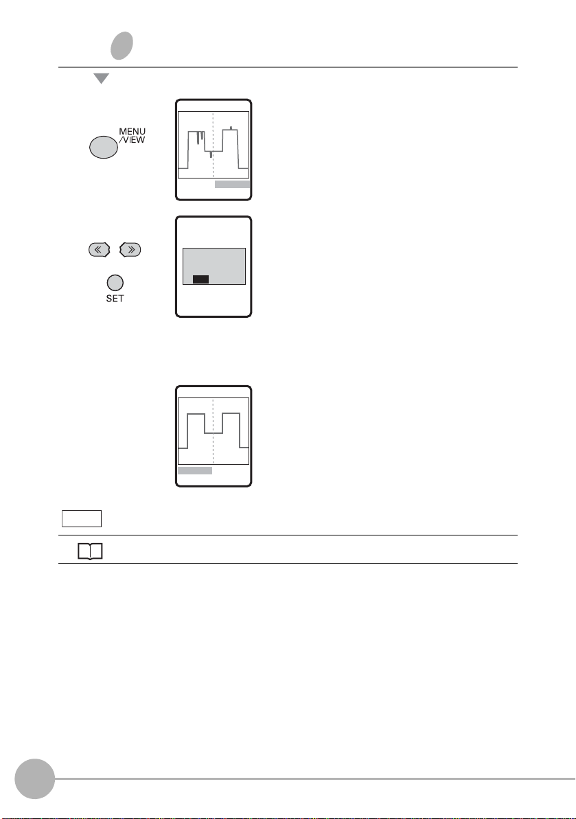
1 Display the screen on the left and
press the MENU/VIEW key.
The confirmation message is
displayed.
MEAS
EXECUTE
FILTER SETTING
AUTOMATICALLY.
YES NO
MEAS
1TEACH 2IMAGE
2 Move to [YES] and press the SET
key.
The optimum profile acquisition
conditions are automatically set.
When profiles are not displayed as intended
Troubleshooting p.213
60
Flow of Basic Setup
ZG2 User’s Manual
Page 64

Registering the profile of the reference target
step3
1TEACH 2IMAGE
MEAS
1 Select [TEACH].
2
BASIC OPERATIONS
MEAS
TEACH
PROFILE
YES NO
1TEACH 2IMAGE
MEAS
1TEACH 2IMAGE
3SENS 4CORECT
2 Move to [YES] and press the SET
key.
This registers the profile. Set the
measurement position and edge
level while viewing the registered
profile. The registered profile is held
in memory until teaching is
performed again.
ZG2 User’s Manual
Flow of Basic Setup
61
Page 65
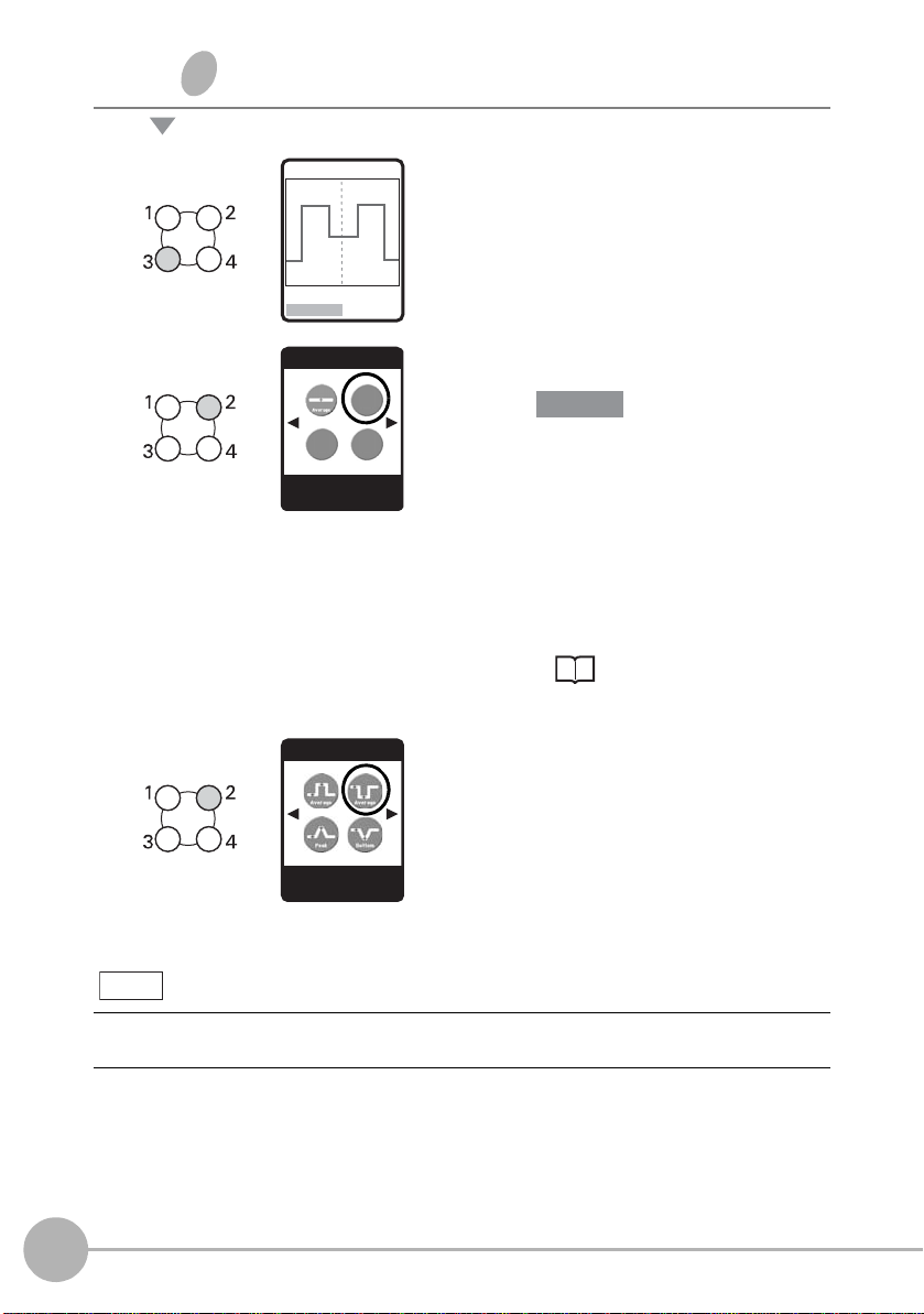
Selecting measurement items
step 4
1TEACH 2IMAGE
3SENS 4CORECT
MEAS
Important
1 Select [SENS].
Note
MEAS/SENS
TASK2:----
←→
P1/ 2
MEAS/ITEM T2
2PTS-2
←→
P2/5
To measure multiple items
2 Select [TASK2].
The default setting for [TASK1] is
[HEIGHT1]. To change [TASK1] to
another measurement item, select
[TASK1] and change to the desired
measurement item. When a
measurement item is changed, the
message "CHANGE ITEM" is
displayed. Move to [YES], and press
the SET key.
How to Select
Measurement Items p.70
3 Select [2PTS-2] from the
measurement items.
Scroll pages by the
→ RIGHT key, and select the
measurement item.
← LEFT/
Simultaneous measurement of up to eight items can be performed. To do this, repeat steps 2
and 3.
62
Flow of Basic Setup
ZG2 User’s Manual
Page 66

Setting the measurement area
step 5
↑↓ 50.000mm
←→
123LINE SET
TRIMMING
Important
Center line
Area for point 1 Area for point 2
1 Adjust the top left of the desired
measurement area, and press the
SET key.
2
BASIC OPERATIONS
Note
TRIMMING
↑↓ 10.000mm
←→
450LINE SET
MEAS/2PTS-2
1ITEM 2CUSTOM
3SCALE
2 Adjust the bottom right of the
desired measurement area, and
press the SET key.
Adjust the area so that the center line
overlaps the vicinity of the area of the
vertical line so as to enclose the two
steps to be measured.
When the desired measurement
area is enclosed, the region in which
measurement points are extracted is
automatically set.
• If the target area is not displayed by automatic setting, select [CUSTOM], and adjust the
area for each individual measurement point.
• To narrow the area in the vertical direction, adjust by the sensitivity adjustment area.
p.99
ZG2 User’s Manual
Flow of Basic Setup
63
Page 67

Adjusting the judgment threshold value
step 6
Profile
Measurement result
Note
HEIGHT1 B01T1
1FILTER 2OUT
1 Switch to the ADJ mode.
2PTS-2 B01T2
109.052 10 mm
LV: 1-320
To switch the task display, use the ↑ UP key/↓ DOWN key.
The profile is continuously
measured.
Perform test measurement while
altering the measurement target.
2 Press the MENU/VIEW key.
The condition setup monitor screen
is displayed.
3 Select [OUT].
64
Flow of Basic Setup
HEIGHT1 B01T1
1JUDGE 2ZERO
3ERROR 4HOLD
4 Select [JUDGE].
ZG2 User’s Manual
Page 68

HEIGHT1/JUDGE
Important
1.HIGH
2.LOW
to 6,000 mm
5 Set the HIGH and LOW
thresholds.
Note
To change numerical values, use the
digits use the
The default judgment threshold value is the "rated measurement range of the currently
connected Sensor Head ÷ 4".
Example: As the measurement range of the ZG2-WDS70 (diffuse reflection type) is "60 mm"
(±30 mm), the default judgment threshold value becomes "60 ÷ 4=15". So, the default threshold
judgment value is ±15 mm.
← LEFT key/→ RIGHT key.
↑ UP key/↓ DOWN key, and to change the number of
2
BASIC OPERATIONS
ZG2 User’s Manual
Flow of Basic Setup
65
Page 69
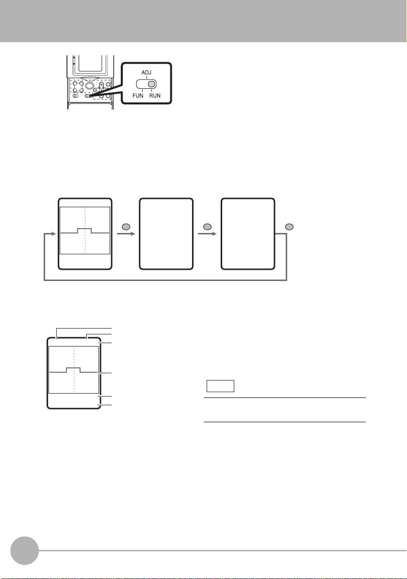
Starting Measurement
/
Profile monitor Digital monitor Eco monitor
109.05210 mm
LV: 1-320
HEIGHT1 B01T1
Measurement items
Bank No.
Task No.
Profile
Measurement result
Sensitivity level
1 Switch to the [RUN] mode.
Measurement will start.
Monitoring the Measurement Status
The measurement information is displayed on the LCD scree n. You can switch the screen
to display different measurement information according to your specific application.
HEIGHT1 B01T1
109.052 10 mm
LV: 1-320
MENU
/VIEW
B01
T1: HEIGHT1
1,109.05210 mm T
2: 2PTS-1
1,109.05210 mm
T3:----
T4:----
Profile monitor
MENU
/VIEW
XXXXms
NORMAL
B01
MENU
VIEW
The currently measured profile is displayed.
When multiple tasks are registered, switch
the profile and display it for each individual
task.
Note
To switch the task display, use the ↑ UP key/
↓ DOWN key.
66
Starting Measurement
ZG2 User’s Manual
Page 70

Digital monitor
B01
T1: HEIGHT1
1,109.05210 mm
T2: 2PTS-1
1,109.05210 mm
T3:----
T4:----
↑↓ P1/2
Bank No.
Task No.: measurement items
Measurement result
Note
B01
XXXXms
NORMAL
Bank No.
Measurement cycle
CCD mode
When the desired
region of the profile
is enclosed, it is
displayed
magnified.
While the profile display is
magnified, "SU" is displayed
at the bottom right of the
screen.
Measurement results for each individual t ask
are displayed as a list as numerical values.
To switch between the tasks 1 to 4 and tasks
5 to 8 displays, use the
↑ UP key/↓ DOWN
key.
2
Eco monitor
The measurement cycle and CCD mode are
displayed.
Magnifying the Profile Display
A specified area of the profile display can be magnified.
RUN mode-F4 key-[MGNIFY]
MGNIFY
↑↓ 50.000mm
←→
123LINE SET
HEIGHT1
1MGNIFY 2RESET
SU
BASIC OPERATIONS
ZG2 User’s Manual
Starting Measurement
67
Page 71

Function Keys
Function keys
11.975 mm
LV: 1-320
HEIGHT1 B01T1
Lock status
In the RUN mode, the following functions
are assigned to function keys F1 to F4.
Function keys Function
F1 If the F1 key is pressed when [I/O]-[I/O LINE]-[TRIGGER]-
[ENABLE] is set, the trigger is input.
F2 The image is displayed. T o return the display to the normal display ,
press the F2 key again.
Measurement is stopped while the image is displayed.
F3 When the F3 key is pressed
and held down for 3 seconds
or longer, the key lock
confirmation message is
displayed. When the key lock
function is ON, the FUN/ADJ/
RUN modes cannot be
switched. To cancel the key
lock, press and hold down the
F3 key for 3 seconds or longer.
F4 Magnifies the profile display.
2
BASIC OPERATIONS
ZG2 User’s Manual
Magnifying the Profile Display p.67
Starting Measurement
68
Page 72

FUNCTION SETTINGS
Setting Measurement Conditions 70
Customizing Measurement Conditions 87
Scaling of Measurement Values 91
Image Adjustment 96
Position Correction 106
Adjusting the Output Conditions of the
Measurement Result 111
Setting Zero Reset 114
Bank Settings 116
System Settings 118
3
FUNCTION SETTINGS
Page 73

Setting Measurement Conditions
Point of inflection
Point of inflection
Step
Step
Edge position Edge position
How to Select Measurement Items
Desired measurement Measurement item and setting
Height Peak, bottom, average
Height at which angle varies
considerably
Step One reference plane
Disparity (indentation and
protrusion) between two reference
planes
Height measurement items
Height measurement items
+[CUSTOM]-[POINT]-[BEND]
2-pt step measurement items
3-pt step measurement items
Reference
p.72
p.83
p.74
p.74
Position Position in X-direction
70
Setting Measurement Conditions
Edge position measurement items
ZG2 User’s Manual
p.77
Page 74
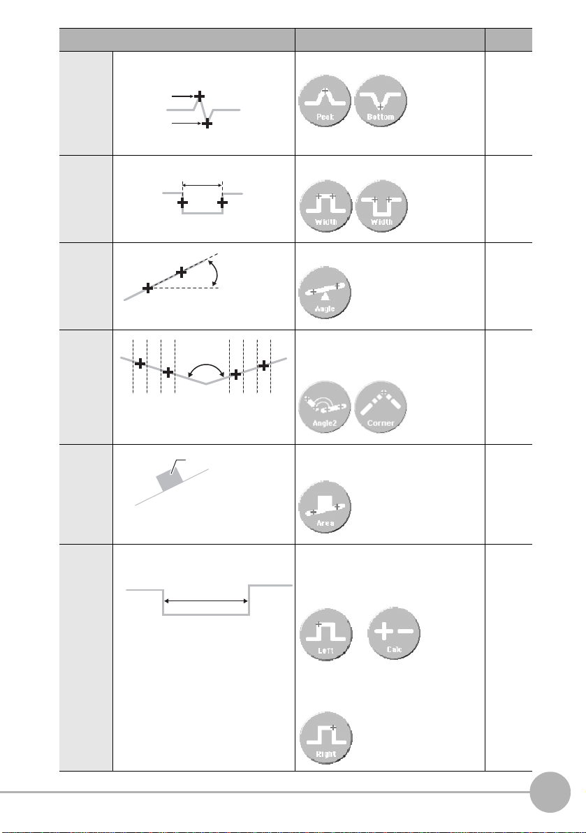
Desired measurement Measurement item and setting
Width
Angle (θ)
P2
P1
Angle2 (θ)
P1
P2
P3
P4
(X, Y)
Cross-sectional
area (mm
2
)
Controller CH1
Width
Controller CH2
Position Position of peak and bottom in
X-direction
Height measurement items
+[CUSTOM]-[POS.]-[X POS]
Width
Angle
Edge width measurement items
Angle measurement items
Reference
p.72
p.88
p.77
3
p.79
FUNCTION SETTINGS
Point of
intersecti
on
Crosssectional
area
Width Measurement by two Sensor Heads
Point of intersection angle, point of
intersection coordinate
measurement items
Cross-sectional area measurement
items
Controller CH1
Edge position measurement items
+ calculation
+
Controller CH2
Edge position measurement items
p.80
p.82
p.77
p.86
ZG2 User’s Manual
Setting Measurement Conditions
71
Page 75
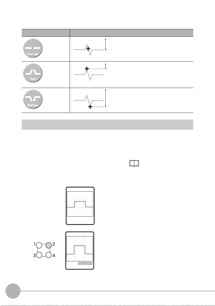
Measuring Height
Height
Height
Height
↑ ↓ 10.000 mm
←→ 450 LINE SET
MEAS/CUSTOM
Three measurement items are provided according to the type of height measurement.
Item Description
Measures the average value
inside a region.
Average
Measures the maximum value
(peak) inside a region.
Peak
Measures the minimum value
(bottom) inside a region.
Bottom
Flow of Operations
1
Assign the desired item from among
the height-related measurement
items to an unused task.
72
Setting Measurement Conditions
MEAS/HEIGHT1
1ITEM 2CUSTOM
3SCALE
step4 Selecting
measurement items p.62
2 Enclose the desired
measurement area.
The measurement region is
automatically set.
In the EXP menu, select [AUTO] and
set up this item.
3 Check that the region is set
correctly.
When the region is not ideally set to
the desired measurement position,
select [CUSTOM]-[REGION] to
adjust the region.
ZG2 User’s Manual
Page 76

Note
Start position
End position
Setting value Description
Reference
REGION Fine-adjusts the measurement region when it is not ideally
set by AUTO.
–
MGNIFY Magnifies the profile display. p.87
POS. (measurement
position)
Selects whether to output the position of the measurement
value as the position in the height direction (Z coordinate)
or as the position in the horizontal direction (X coordinate).
p.88
MEAS (enabled only in
EXP menu)
Sets in more detail which height in the line beam that the
target is to be measured at.
Settings: AVE, PEAK, BTM, BEND
p.89
Adjust the start and end points of the measurement region so that the desired measurement
position is enclosed.
Hint for adjusting the measurement region
Note
Custom settings available for height measurement
3
FUNCTION SETTINGS
ZG2 User’s Manual
Setting Measurement Conditions
73
Page 77
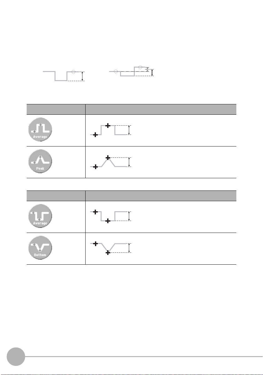
Measuring Step
2-pt step
Step
Step
3-pt step
Step
P2 (average)
P1 (average)
Step
P2 (peak)
P1 (average)
Step
P1 (average)
P2 (average)
Step
P1 (average)
P2 (bottom)
Measures the step from the reference plane.
• When there is one reference plane, select “2-pt step”.
• When there are two reference planes, select “3-pt step”.
<2-pt step>
To measure a protrusion (+ direction) taking the base as the reference plane:
Item Description
Measures the step between the
average values of P1 and P2.
Average
Measures the step between the
average value of P1 and the
maximum value of P2.
Peak
To measure an indentation (- direction) taking the top surface as the reference plane:
Item Description
Measures the step between the
average values of P1 and P2.
74
Average
Bottom
Setting Measurement Conditions
Measures the step between the
average value of P1 and the
minimum value of P2.
ZG2 User’s Manual
Page 78
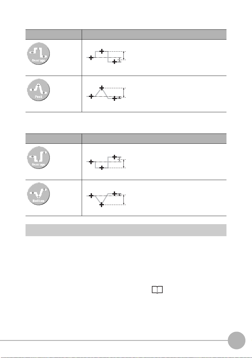
<3-pt step>
Step
P3 (average)
P1 (average)
P2 (average)
Step
P3 (peak)
P1 (average)
P2 (average)
Step
P2 (average)
P1 (average)
P3 (average)
Step
P2 (average)
P1 (average)
P3 (bottom)
To measure a protrusion (+ direction) taking the base as the reference plane:
Item Description
Measures the step between the
average value of P3 taking the
average values of both sides (P1,
Average
Peak
P2) as the reference plane.
Measures the step between the
maximum value of P3 taking the
average values of both sides (P1,
P2) as the reference plane.
To measure an indentation (- direction) taking the top surface as the reference plane:
Item Description
Measures the step between the
average value of P3 taking the
average values of both sides (P1,
Average
Bottom
P2) as the reference plane.
Measures the step between the
minimum value of P3 taking the
average values of both sides (P1,
P2) as the reference plane.
3
FUNCTION SETTINGS
Flow of Operations
The following example describes how to set 2-pt step.
1 Assign the desired item from
ZG2 User’s Manual
among the 2-pt step-related
measurement items to an unused
task.
step4 Selecting
measurement items p.62
Setting Measurement Conditions
75
Page 79
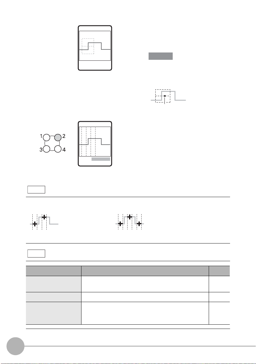
TRIMMING
Important
Center line
P1
(reference)
(step=P2-P1)
P2
P1
(reference) (reference)
P2P3
(step=P3 -(P1+P 2)÷2)
2-pt step 3-pt step
Setting value Description
Reference
REGION Fine-adjusts the measurement region when it is not ideally
set by AUTO.
–
MGNIFY Magnifies the profile display. p.87
POINT (enabled only in
EXP menu)
Sets in more detail which height in the line beam that the
target is to be measured at.
Settings: AVE, PEAK, BTM
p.89
2 Enclose the desired
measurement area.
In the EXP menu, select [AUTO] and
set up this item.
↑↓ 10.000 mm
←→ 123 LINE SET
Adjust the region so that the center line
is aligned with the “mid point between
the top and bottom of the step.”
MEAS/2PTS-1
3 Check that the region is set
correctly.
When the region is not ideally set to
the desired measurement position,
select [CUSTOM]-[REGION] to
Note
1ITEM 2CUSTOM
3SCALE
Hint for adjusting the measurement region
adjust the region for each
measurement point.
Adjust the start and end points of the region for each measurement point.
Note
Custom settings available for step measurement
76
Setting Measurement Conditions
ZG2 User’s Manual
Page 80

Measuring Position and Width
Edge position
Edge position
Width
Width
Performs measurement taking the point of intersection of t he profile and the edge lev el as
an edge.
<Edge position>
Item Description
Measures the edge that is
positioned on the left side inside
a region.
Left
Measures the edge that is
positioned on the right side inside
a region.
Right
<Edge width>
Item Description
Measures the width of the
protrusions between edges that
are extracted inside a region.
Width
Measures the width of the
indentations between edges that
are extracted inside a region.
Width
3
FUNCTION SETTINGS
The following example describes how to set edge width.
ZG2 User’s Manual
Flow of Operations
1 Assign the desired item from the
edge width-related measurement
items to an unused task.
step4 Selecting
measurement items p.62
Setting Measurement Conditions
77
Page 81

TRIMMING
Important
Center line
Edge level
Start position End position
Setting value Description
Reference
REGION Fine-adjusts the measurement region when it is not ideally
set by AUTO.
–
MGNIFY Magnifies the profile display. p.87
EDGELV (enabled only
in EXP menu)
Selects the edge level and edge search direction. p.90
↑↓ 10.000 mm
←→ 123 LINE SET
2 Enclose the desired
measurement area.
In the EXP menu, select [AUTO] and
set up this item.
Adjust the region so that the center
line is aligned with the “edge to be
detected.”
MEAS/WIDTH1
3 Check that the region is set
correctly.
When the region and edge level are
not ideally set to the desired
1ITEM 2CUSTOM
3SCALE
Note
Adjust the start and end points of the measurement region, and edge level so that the desired
measurement position is enclosed.
The edge level can be changed only in the EXP menu.
Note
Hint for adjusting the measurement region
Custom settings available for position and width measurement
measurement position, adjust each
of region and edge level.
78
Setting Measurement Conditions
ZG2 User’s Manual
Page 82

Measuring Angle
Angle (θ)
P2
P1
Setting value Description
Reference
MGNIFY Magnifies the profile display. p.87
POINT (measurement
value)
Sets in more detail which height in the line beam that the
target is to be measured at.
Settings: AVE, PEAK, BTM
p.89
The angle of the profile inside the region is measured. Measurement of the angle is
enabled only in the EXP menu.
Item Description
The average values inside the
region are each extracted as
points. A straight line is drawn
Angle
between the two extracted
points, and the angle formed by
the intersection between that
straight line and the X-axis is
measured as the angle.
Flow of Operations
1 Switch to the EXP menu.
Switching the menu p.55
2 Assign the angle measurement
item to an unused task.
step4 Selecting
measurement items p.62
3
FUNCTION SETTINGS
MEAS/CUSTOM
1REGION 2MGNIFY
3POINT
Note
ZG2 User’s Manual
Custom settings available for angle measurement
3 Select [ CUSTOM ]-[ REGION ], and
set two regions on the line.
Setting Measurement Conditions
79
Page 83

Measuring Angle and Point of Intersection
Angle2 (θ)
P1
P2
P3
P4
P1
P2
P3
P4
Measurement
point (X, Z)
The angle at the point of intersection of two li nes a nd p oin t o f int ersecti on co ordi nates are
measured. Measurement of the angle and point of intersection is en abled onl y in t he EXP
menu.
<Point of intersection angle>
Item Description
Extracts the average value of
each region as points P1 to
P4, respectively. Points P1/P2
Angle2
<Point of intersection coordinates>
Item Description
Corner
and P3/P4 are each joined by
a straight line, and the angle
formed by the intersection
between these two straight
lines is measured. The angle
is calculated in the clockwise
direction taking the line formed
by joining points P1 and P2 as
the reference.
Extracts the average value of
each region as points P1 to P4,
respectively. Points P1/P2 and
P3/P4 are each joined by a
straight line, and, the height (Z
coordinate or position (X
coordinate) of that point of
intersection is measured.
80
Flow of Operations
The following example describes how to set point of intersection angle.
1 Switch to the EXP menu.
2 Assign the point of intersection
Setting Measurement Conditions
angle measurement item to an
unused task.
Switching the menu p.55
step4 Selecting
measurement items p.62
ZG2 User’s Manual
Page 84

MEAS/CUSTOM
Setting value Description
Reference
MGNIFY Magnifies the profile display. p.87
POS (measurement
position) (enabled only at
point of intersection
coordinate measurement)
Selects whether to output the position of the
measurement value as the position in the height direction
(Z coordinate) or as the position in the horizontal direction
(X coordinate).
p.88
POINT (measurement
point)
Sets in more detail which height in the line beam that the
target is to be measured at.
Settings: AVE, PEAK, BTM
p.89
1REGION 2MGNIFY
3POINT
3 Select [ CUSTOM ]-[ REGION ], and
set two regions each for the two
straight lines.
Note
Custom settings available for angle and point of intersection measurement
3
FUNCTION SETTINGS
ZG2 User’s Manual
Setting Measurement Conditions
81
Page 85

Measuring Cross-sectional Area
Setting value Description
Reference
MGNIFY Magnifies the profile display. p.87
The cross-sectional area of the profile inside the region is measured. Measurement of the
cross-sectional area is enabled only in the EXP menu.
Item Description
The cross-sectional area of the object
is measured.
The cross-sectional area is calculated
Area
Start position
End position
by integrating the distance between
each of the measurement point and
the bottom face, with the line formed
between the two points that intersect
the start and end points of the
measurement region taken to be the
bottom face.
Flow of Operations
1 Switch to the EXP menu.
Switching the menu p.55
2 Assign the cross-sectional area
measurement item to an unused
task.
step4 Selecting
measurement items p.62
MEAS/CUSTOM
1REGION 2MGNIFY
Note
82
Setting Measurement Conditions
Custom settings available for cross-sectional area measurement
3 Select [ CUSTOM ]-[ REGION ], and
set the region for cross-sectional
area measurement.
ZG2 User’s Manual
Page 86

Measuring Point of Inflection
Height
Measures the height of the point (point of inflection) where the angle varies the most
within a measurement region.
This item is useful for measuring positions that cannot be selected by the PEAK or BTM
settings.
Item Description
Height-related
measurement items
Measures the height of the point
where the angle varies the most
within a measurement region.
3
Peak
Average
Bottom
Flow of Operations
MEAS/HEIGHT1
FUNCTION SETTINGS
1 Switch to the EXP menu.
Switching the menu p.55
2 Assign the desired item from
among the height-related
measurement items to an unused
task.
step4 Selecting
measurement items p.62
3 Select [ CUSTOM ]-[ REGION ], and
set the region.
ZG2 User’s Manual
1ITEM 2CUSTOM
3SCALE
Setting Measurement Conditions
83
Page 87
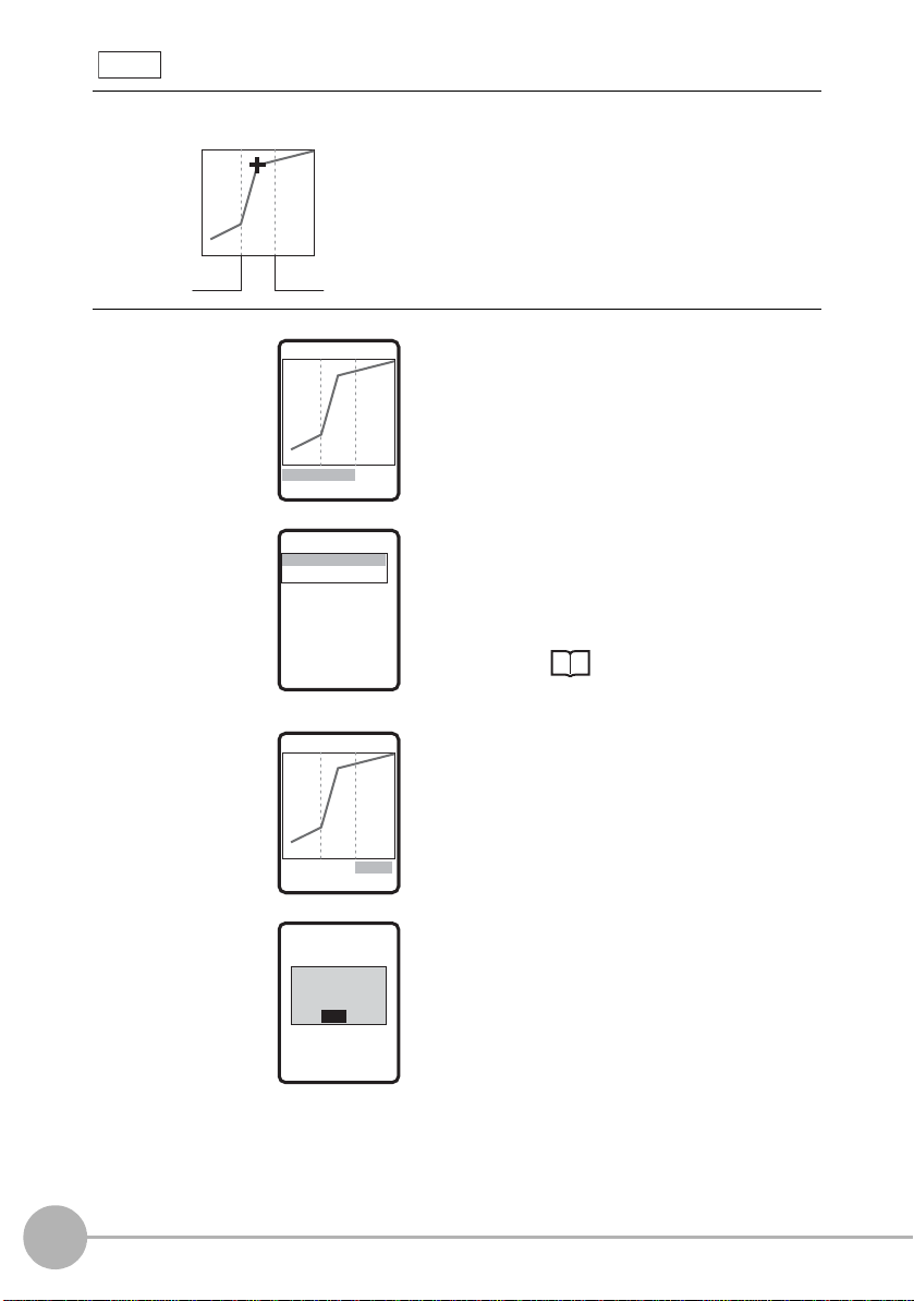
Note
Start position End positi
Adjust the start and end points of the measurement range so that the point of inflection to be
detected is enclosed.
Hint for adjusting the measurement region
MEAS/BEND
MEAS/LV
[ 3 ]OK
1TARGET 2LV
MEAS/TARGET
MEAS/BEND
1. UPSWING
2. DOWNSWING
4 Select [CUSTOM]-[MEAS]-
[BEND]-[TARGET].
5 Select [DOWNSWING] or
[ UPS W ING] to match the
orientation of the point of
inflection to be detected.
84
Setting Measurement Conditions
1TARGET 2LV
MEAS/BEND
MEAS/LV
[ 3 ]OK
1TARGET 2LV
MEAS/LV
[ 3 ]OK
UPSWING/DOWNSWING
p.85
6 When noise, etc. prevents the
profile from stabilizing, increase
the [LV] setting.
Setting range: 1 to 5 (default value: 1)
ZG2 User’s Manual
Page 88
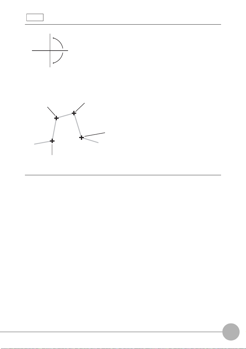
Note
X
Z
0°
+
-
The ZG2 treats angles as follows.
To measure the position where the angle of inclination is var ying from “small → l arge,” s elect
[UPSWING].
To measure the position where the angle of inclination is varying fr om “large → small,” select
[DOWNSWING].
DOWNSWING
UPSWING/DOWNSWING
DOWNSWING
angle:15°
3
FUNCTION SETTINGS
angle:85°
angle:5°
angle:-85°
UPSWING
angle:-10°
UPSWING
ZG2 User’s Manual
Setting Measurement Conditions
85
Page 89

Calculating Measurement Values
Important
<Calculation>
The measurement results of other tasks can be used for calculation. The calculation
setting is enabled only in the EXP menu.
Item Description
Set any equation to perform addition/subtraction on the
measurement result. The equation can be substituted with
measurement results obtained by other tasks. Also, when using two
Calc
Measuring Wide Measurement Targets p.185
Calculations Performed on Measurement Values Obtained on Multiple Channels
p.190
Controllers in a gang-mount configuration, calculations can also be
performed across channels.
Allowable equation: K+mX+nY
• EK range: -999.99999 to 999.99999 (default value: 0.00000)
• Em/n range:-10.0 to 10.0 (default value: 1.0)
• X/Y range: OFF (default value: OFF), TASK1 to TASK7 (Only
task Nos. smaller than the task No. to which a
calculation is set can be set.)
In a gang-mount configuration, select the channel
first in the additional channel selection menu before
setting the task number.
86
When Controllers are gang-mounted, set calculation on the Controller set as channel 1 (CH1).
Calculation cannot be set on the CH2 Controlled.
Deleting measurement items
<Deleting measurement items>
Item Description
Delete the measurement items that are set to the currently selected
task.
Delete
Setting Measurement Conditions
ZG2 User’s Manual
Page 90
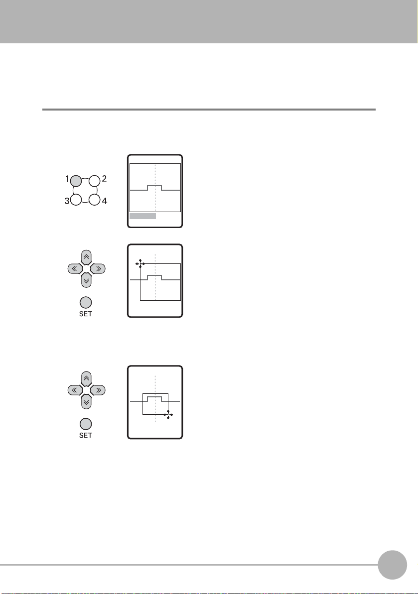
Customizing Measurement Conditions
Magnifying the Profile Display
A specified area of the profile display can be magnified.
FUN mode-[MEAS]-[SENS]-[TASK1 to 8]-[CUSTOM]-[MGNIFY]
MEAS/MGNIFY
1MGNIFY 2RESET
MEAS/MGNIFY
↑↓ 50.000mm
←→
123LINE SET
MEAS/MGNIFY
↑↓ 10.000mm
←→
450LINE SET
1 Select [MGNIFY].
2 Adjust the top left of the desired
measurement area by the ↑, ↓, ←
and → keys, and press the SET
key.
3 Adjust the bottom right of the
desired measurement area by the
↑, ↓, ← and → keys, and press the
SET key.
3
FUNCTION SETTINGS
ZG2 User’s Manual
Customizing Measurement Condition s
87
Page 91

MEAS/MGNIFY
X position
(horizontal direction)
Z position
(height direction)
MAGNIFY
P ROFILE
YES
NO
←→↑↑ SE
4 Move to [YES] and press the SET
key.
MEAS/MGNIFY
1MGNIFY 2RESET
The profile in the specified area is
displayed magnified.
Changing Measurement Positions
Select whether to output the position of the measurement value as the position in the
height direction (Z coordinate) or as the position in the horiz ontal direction (X coordinate).
Selection of measurement position is enabled when measuring height and point of
intersection coordinates.
FUN mode-[MEAS]-[SENS]-[TASK1 to 8]-[CUSTOM]-[POS.]
Setting value Description
Z POS. (height direction)
X POS. (horizontal direction)
88
Customizing Measurement Conditions
Outputs the position of the measurement value as the
position in the height direction (Z coordinate). (default value)
Outputs the position of the measurement value as the
position in the horizontal direction (X coordinate).
ZG2 User’s Manual
Page 92
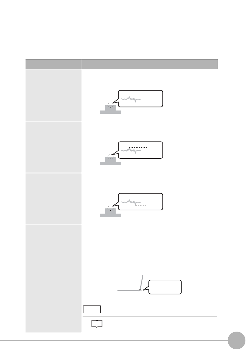
Changing Measurement Points
Average
Peak
Bottom
Point of
inflection
Setting UPSWING, DOWNSWING and LV
Measuring Point of Inflection p.83
Any measurement point inside the received light area can be measured. Set this menu
item when measuring small unevenness.
The measurement point setting is enabled only in the EXP menu.
FUN mode-[MEAS]-[SENS]-[TASK1 to 8]-[CUSTOM]-[POINT]
Setting value Description
AVE (average) Measures the average value inside the line beam.
PEAK Measures the peak position of the line beam.
BOTTOM Measures the bottom position of the line beam.
3
FUNCTION SETTINGS
BEND (point of inflection)
ZG2 User’s Manual
Measures the height of the point (point of inflection) where
the angle of the profile varies the most within a
measurement region. This item is displayed only when the
measurement item [HEIGHT] is set. This item is useful for
measuring positions that cannot be selected by the PEAK
or BTM settings.
E
Note
Customizing Measurement Condition s
89
Page 93
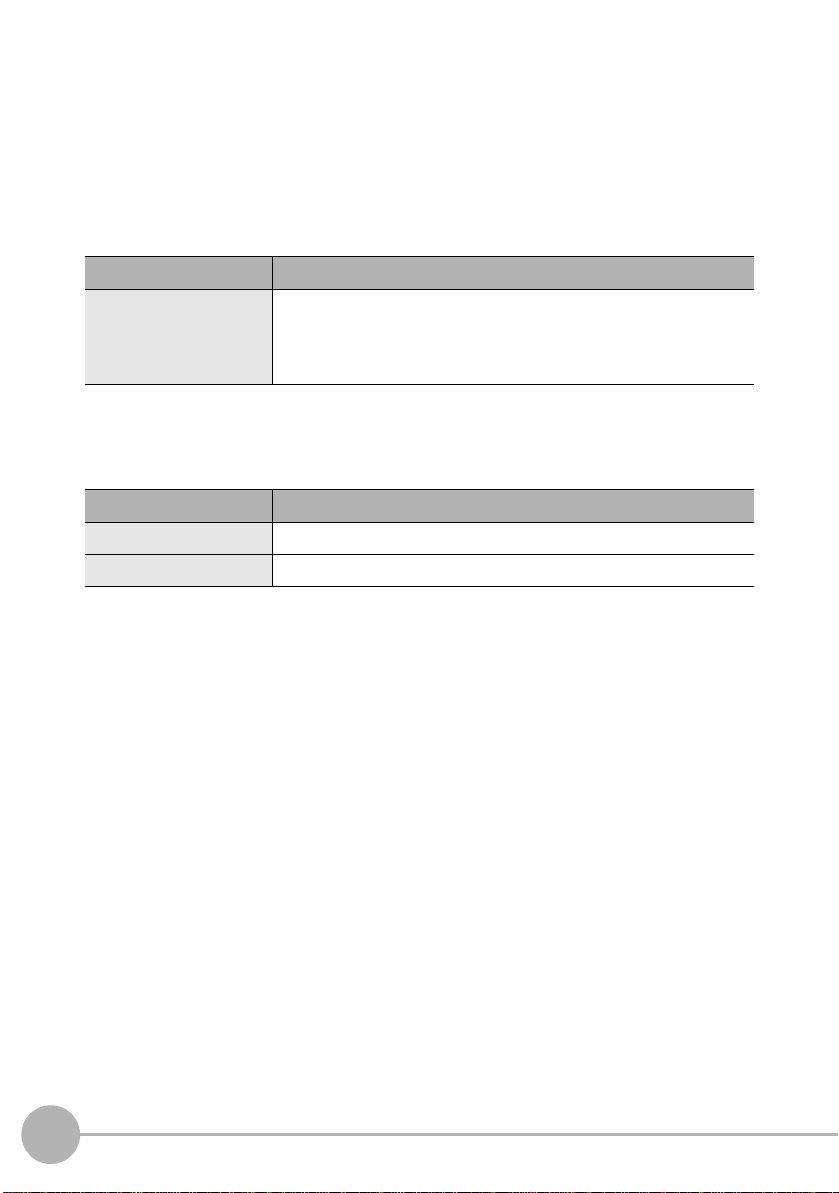
Changing the Edge Level and Edge Direction
Set the edge level and edge direction when selecting edge-related measurement items.
These settings are enabled only in the EXP menu.
FUN mode-[MEAS]-[SENS]-[TASK1 to 8]-[CUSTOM]-[EDGELV]
Changing the edge level
Setting value Description
Edge level Align the line of the edge level with the edge to be detected.
The range differs according to the CCD mode.
Standard and high-resolution mode: 0 to 399
High-speed mode: 0 to 199
Selecting the edge direction
Set the edge search direction.
Setting value Description
→ Forward direction The “1st edge from the left” in the region is searched for.
← Reverse direction The “1st edge from the right” in the region is searched for.
90
Customizing Measurement Conditions
ZG2 User’s Manual
Page 94
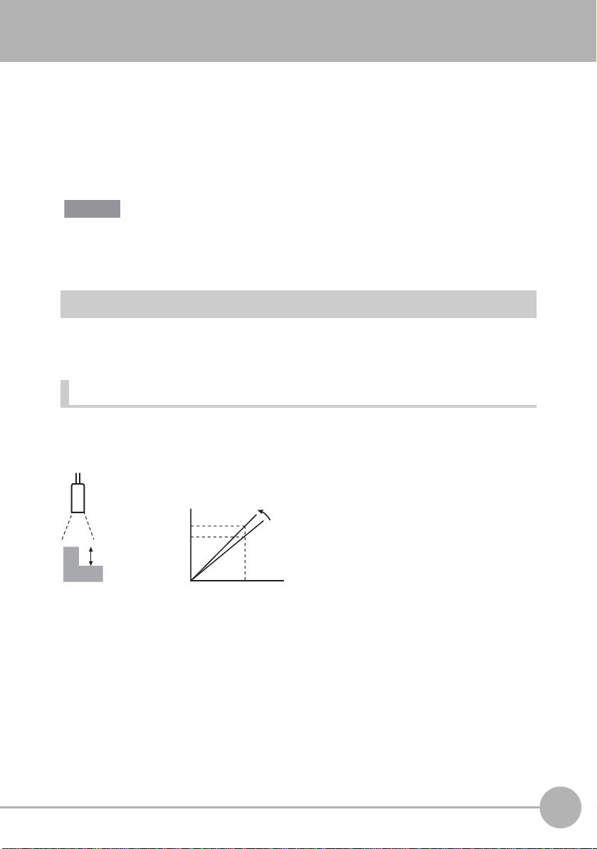
Scaling of Measurement Values
Important
5
5
4.95
0
Measurement
value (mm)
Actual size value (mm)
This error is corrected.
If scaling is set, differences between measurement values and actual sizes, that occur
due to the color or material of the measurement target or other factors, can be corrected.
There are two scaling setup modes, “automatic setting” and “manual setting.” In the
automatic setting mode, actual measurement is performed, and in the manual setting
mode, the correction values are set manually.
(default value: OFF)
The settings below return to the default settings when scaling is set. Set these items after
scaling settings have been completed.
• Zero reset
Automatic Setting Method
Measurement is actually performed, and correction v alues a re set for tho se measurement
values.
1-pt scaling
Measurement is performed once, and the actual size value for the measurement value is
set. Set scaling by this method when 2-pt step, 3-pt step and edge width is set.
3
FUNCTION SETTINGS
ZG2 User’s Manual
Scaling of Measurement Values
91
Page 95
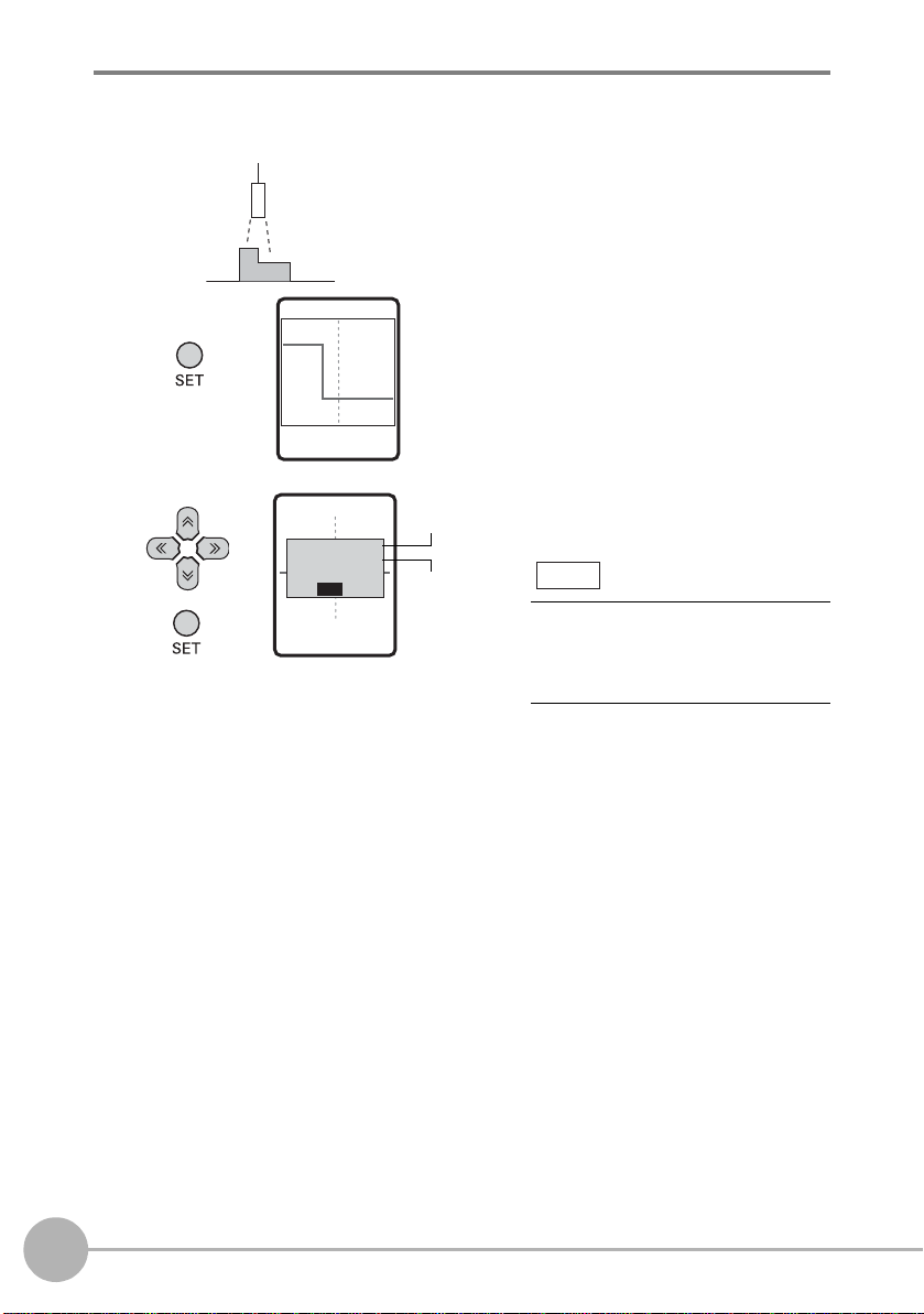
FUN mode-[MEAS]-[SENS]-[TASK1 to 8]-[SCALE]-[AUTO]
MEAS/AUTO
FIRST POINT
SET
INPUT
CORRECT VALUE
MEAS/AUTO
4.95000
[ 5.00000]
OK
Measurement
value
Actual
size
value
Note
1 Set the measurement target in
place, and press the SET key.
The measurement value is
displayed.
2 Input the actual size value on the
lower section.
To change numerical values, use the
↑ key/↓ key, and to change the
number of digits use the → key/→
key.
92
Scaling of Measurement Values
ZG2 User’s Manual
Page 96

2-pt scaling
1st point 2nd point
Measurement is performed at two positions, and actual size values are set for those
measurement values. Set scaling by this method when height and edge position are set.
Measurement
value (mm)
10
9
4
3
0
3
Actual size value (mm)
10
3
FUNCTION SETTINGS
ZG2 User’s Manual
Scaling of Measurement Values
93
Page 97

FUN mode-[MEAS]-[SENS]-[TASK1 to 8]-[SCALE]-[AUTO]
MEAS/AUTO
FIRST POINT SET
INPUT CORRECT VALUE
MEAS/AUTO
9.05000
[ 10.00000]
OK
Measurement
value
Actual
size value
Note
INPUT CORRECT VALUE
MEAS/AUTO
4.02000
[ 3.00000]
OK
1 Set the measurement target in
place, and press the SET key.
The measurement value is
displayed.
2 Input the actual size value on the
lower section.
To change numerical values, use the
↑ key/↓ key, and to change the
number of digits use the → key/→
key.
94
Scaling of Measurement Values
3 Move the position of the
measurement target, and press
the SET key.
The measurement value is
displayed.
4 Input the actual size value on the
lower section.
ZG2 User’s Manual
Page 98

Manual Setting Method
‑4.0000
(mm)
4.0000
Measurement value
Displacement of
measurement
target
(mm)
Measurement value
Displacement of
measurement target
Span and offset can be set by inputting numerical values manually to fine-tune the
measurement values. These can be set for each individual task. Span and offset are
automatically set after scaling is executed. So, modify these settings as necessary. Set
scaling by this method when angle, point of intersection angle, point of intersection
coordinates, and cross-sectional area are set. Manual setting is enabled only in the EXP
menu.
FUN mode-[MEAS]-[SENS]-[TASK1 to 8]-[SCALE]-[MANUAL]
Setting value Description
SPAN Sets the inclination of the sensor characteristics as a coefficient.
Range: -4.0000 to 4.0000
3
FUNCTION SETTINGS
OFFSET Adds/subtracts a fixed value to or from the measurement value.
Range: -999.99999 to 999.99999
ZG2 User’s Manual
Scaling of Measurement Values
95
Page 99

Image Adjustment
Important
Adjusting Sensitivity
The sensitivity of the Sensor Head can be adjusted so that shapes are accurately
captured even if the shape, color, material, etc. of the measurement target is influenced.
The default setting is [MULTI].
Sensitivity Adjustment Functions of the ZG2 Series p.26
FUN mode-[MEAS]-[IMAGE]-[LD-POWER]
Setting value Description
HS_MULTI
(high-speed MULTI)
MULTI Measurement is performed with the sensitivity adjusted for each
AUTO Measurement is performed with the sensitivity adjusted
FIXED Measurement is performed with the sensitivity fixed.
This is a higher speed version of the MULTI mode.
This method is suitable when the brightness of the measurement
target surface fluctuates to a large degree but the measurement
tact time must be increased.
individual line in the measurement region.
This method is suitable when the brightness of the measurement
target surface fluctuates to a large degree.
automatically based on the sensitivity information in the
measurement region. This method is suitable when the brightness
of the measurement target surface is uniform.
This method is suitable when accurate measurements cannot be
made at the [AUTO] setting, for example, for lines on which
measurement targets of various colors are fed alternately.
96
[MULTI] and [HS MULTI] are effective as a sensitivity adjustment function only when measuring
stationary measurement targets. When the measurement target cannot be made stationary,
use [AUTO] or [FIXED].
Note
The measurement cycle differs according to the preset sensitivity. The measurement cycle
can be checked by the ECO monitor in the RUN mode.
Image Adjustment
Measurement cycle
Eco monitor p.67
ZG2 User’s Manual
Page 100

Detailed setting of sensitiv ity adjustment
Important
The sensitivity adjustment upper/lower limits and interval can be adjusted in the EXP
menu.
LD-POWER
High
LV4 40
Upper
limit value
Lower
limit value
LV1
Low
Measurement is
performed with
sensitivity adjusted
for several lines in
the upper/lower limit
range.
Measurement is
performed with
sensitivity
adjusted for each
individual line in
the upper/lower
limit range.
Measurement is
performed with
sensitivity
adjusted
automatically in
the upper/lower
limit range.
Detailed setting of HS MULTI (high-spee d MULTI) sensitivity
FUN mode-[MEAS]-[IMAGE]-[LD-POWER]-[HS MULTI]
Setting value Description
CUSTOM HIGH Sets the sensitivity adjustment upper limit.
Range: LV1 to LV440 (default value: LV320)
(when high power mode is used, LV1 to LV320)
LOW Sets the sensitivity adjustment lower limit.
Range: LV1 to LV440 (default value: LV1)
(when high power mode is used, LV1 to LV320)
IMAGE
NUM
(lighting
count)
Sets the lighting count when measurement is executed.
Setting range: 2 to 10 (default value: 5)
The measurement time becomes proportionately shorter as a
smaller lighting count is set. However, measurement sometimes
becomes unstable. If this happens, set a larger lighting count value.
SEARCH The optimum lighting sensitivity is set automatically matched to the
measurement target set in place.
FIXED sensitivityAUTO sensitivityHS MULTI sensitivity MULTI sensitivity
Measurement is
performed at the
preset sensitivity
level.
3
FUNCTION SETTINGS
• When [HS MULTI] is selected, be sure to execute [SEARCH]. Otherwise, the lighting
sensitivity will not be set to the optimum value.
ZG2 User’s Manual
Image Adjustment
97
 Loading...