

Omron ZFX-SC50, ZFX-SC50W, ZFX-SC50R, ZFX-SC90, ZFX-SC90W Instruction Sheet
...
ZFX-SC50□
形
ス マ ート セ ン サ
形ZFX-C□□用
セ ン サ ヘ ッド
取扱説明書
このたびは、本 製品をお買い上げいただきまして、まことにありがとう
ございます。ご使用に際しては、次の内容をお守りください。
・電気の知識を有する専門家が扱ってください。
・この取扱説明書をよくお読みになり、十分にご理解のうえ、正しく
ご 使 用 くだ さ い 。
・この取扱説明書はいつでも参照できるように大切に保管ください。
* 1 8 3 5 9 9 3 - 0 I *
OMRON Corporation
©
●警告表示の意味
正しい取扱いをしなければ、この危険のために、軽傷・中程度の
傷害を負ったり、万一の場合には重傷や死亡に至る恐れがあり
警告
ます。また、同様に重大な物的損害を受ける恐れがあります。
形ZFX-SC50□は可視光を放射しており、まれに目に
悪影響を及ぼす恐れがあります。センサヘッドの照射
光を直視しないでください。被写体が鏡面反射体の場
合は、反射光が目に入らないようにしてください。
以下に示すような項目は安全を確保する上で必要なことですので必ず守ってください。
1. 設置環境について
・引火性、爆発性ガスの環境では使用しないでください。
・操作や保守の安全を確保するため、高電圧機器や動力機器から離して設置してくださ
い。
・取付けにおいて、ねじの締め付けは確実に行ってください。
2. 電源および配線について
・高圧線、動力線と当製品の配線は別配線としてください。同一配線あるいは同一ダクトに
すると誘導を受け、誤動作あるいは破損の原因になることがあります。
3. その 他
・本製品を分解したり、修理、改造したりしないでください。
・廃棄するときは、産業廃棄物として処理してください。
・異臭がする、本体が非常に熱くなる、煙が出るなどの異常が起こった場合 、すぐに使用を
中止し、電源を切った状態で当社支店・営業所までご相談ください。
製品が動作不能、誤動作、または性能・機器への悪影響を防ぐため、
以下のことを守ってください。
1.設置場所について
次のような場所には設置しないでください。
・周囲温度が定格の範囲を越える場所
・温度変化が急激な場所(結露する場所)
・相対湿度が 35 〜 85%RH の範囲を超える場所
・腐食性ガス、可燃性ガスがある場所
・塵埃、塩分、鉄粉がある場所
2007-2009
All Rights Reserved.
安全上のご注意
警告
安全上の要点
使用上の注意
・振動や衝撃が直接加わる場所
・強い外乱光(レーザ光、アーク溶接光、紫外光など)があたる場所
・直射日光があたる場所や暖房器具のそば
・水・油・化学薬品の飛沫がある場所
・強磁界、強電界がある場所
2.電源および接続、配線について
・センサヘッドの着脱は、必ず電源を切った状態で行ってください。電源 ON のまま行う
と故障の原因になります。
・センサヘッドとアンプユニットは、取扱説明書で指定した組合せで使用してください。
3.光軸、検出範囲について
光 軸 中 心 はセンサヘッドごとにばらつくことがありますので 、取 付 けるときは必 ずアンプ
ユニットの液晶モニタで画像の中心と検出範囲を確認してください。
4.通気膜について
・通気膜をはがしたり、先の尖ったものでつついたりしないでください。
保護構造を満足できなくなるおそれがあります。
・通気膜はふさがないでください。センサヘッド前面のパネルが曇るおそれがあります。
5.ピント調整ボリュームについて
ピント調整ボリュームは 5N・m 以下で回してください。
破 損 す る 恐 れ が ありま す 。
6 .オプション照 明 用コネクタに ついて
オプション照明を接続しない場合は、コネクタキャップを必ず装着してください。
保護構造を満足することができません。
7.保守点検について
・ セ ン サ ヘ ッド や ア ン プ ユ ニ ット の 清 掃 に は 、シ ン ナ ー 、ア ル コ ー ル 、ベ ン ジ ン 、ア セト ン 、灯 油
類は使用しないでください。
・センサヘッド前面のパネルに 、大きなゴミやホコリが付いた場 合 は、ブロアブラシ ( カメラレ
ンズ用 ) で 吹き飛ばしてください。呼 気 で吹き飛ば すことは避 けてください 。
・小さなゴミやホコリは、柔らかい布で丁寧にふきとってください。強くふくことは避けてくだ
さい。キズがつくと、誤検出の原因になります。
8.設置に関するご注意
取付けねじは、規定のトルクで締め付けでください。
推奨締付けトルク M4:1.2N・m, 1/4-20UNC:2.6N・m
■LEDの安全について
本製品は IEC62471 により、リスクグループ1に分類されます。
Risk Group 1
IEC 62471
■各部の名称と機能
(1)照明部
(5)ピント調整
ボリューム
(7)オプション
照明用コネクタ
(2)受光部
(1)照明部
LED照明部です。
(2)受光部
画像を取込みます。
(3)コネクタ
ア ン プ ユ ニ ット に 接 続 し ま す 。
(3)コネクタ
(4)センサヘッド
固定用治具
(6)通気膜
(4)センサヘッド固定用治具
センサヘッドを取付けるための治具です。
4方向のどの側面にでも取付けることができます。
(5)ピント調整ボリューム
画像のピントを調整をするときに使用します。
(6)通気膜
前 面パネルの 曇りを防 止します。
(7)オプション照明用コネクタ
オプション照明を接 続する際に使用します。
■フ ェ ラ イト コ ア の 装 着
センサヘッドの本体側およびコネクタ側にフェライトコア(付属品)を装着してください。
フ ェ ラ イト コ ア
■固定用治具の取付
センサヘッドの側面に、固定用治具 ( 付属品 )
を 装 着 し てくださ い 。
固定用治具は 4 方向どの側面にも取付けるこ
とが できます 。
・ZFX-SC50/SC50W
(1) 固定用治具の片側のツメ2 つをヘッド本体
の 2 つの溝に合わせます。
(2)もう1 方のツメを押し込みます。
カチッと音がするまで押し込んでください。
(3) 固定用治具がセンサヘッドに固定されている
ことを 確 認します 。
・ZFX-SC50R
(1) 固定用治具のベース(黒色)の突起部を本体
の溝に合わせて本体に取り付けます。
(2)固定用治具のブラケット(銀色)をベースに合わ
せて本 体に取り付 けます。
(3) 付属のネジ(M3×6)でベースとブラケットを締め
つけます 。
推奨トルク値 :0.54N・m
ツメ
固定用治具
■固定用治具の取外し
固定用治具と本体ケースの隙間(2 カ所のどち
ら か )に 、マ イ ナ スド ラ イ バ ー を 差 し 込 ん で 外 し て く
ださい 。
固定用治具
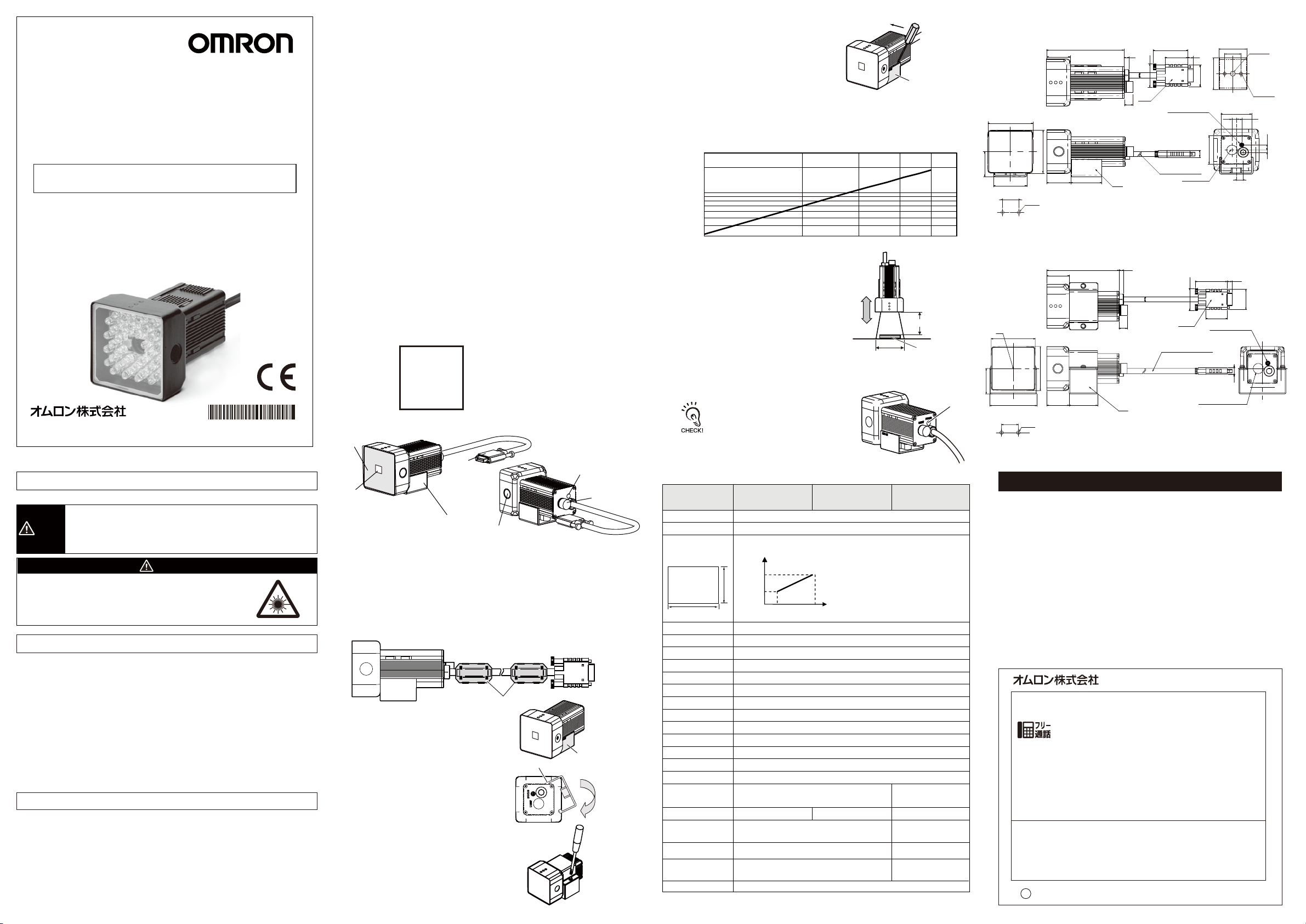
■設置距離
次のグラフは検出範囲と設置距離の関係を表したものです。センサヘッドの形式ごとに値
は異なりますので、形式を十分ご確認の上、グラフをご覧ください。
300
100
設置距離L[mm]
30
10
検出範囲H[mm]
(例)
計測対象箇所に必要な検出範囲が
20mmで形ZFX-SC50のセンサヘッドを
使用する場合、センサヘッド設置距離は
70mmとなります。
■設置手順
検出範囲(H)
検出距離(L)
ワーク
(1)光学図表から読取った設置距離にセンサヘッドを設置します。
( 2 )ピ ント 調 整 ボ リ ュ ー ム を 左 右 に 回 し て ピ ント を 合 わ せ ま す 。
ピント調整ボリュームは多回転ボリュームになってい
ますが、上下限位置で回転が止まります。故障の原
因となりますので、上下限位置以上は無理にボリュ
ームを回さないでください。(最初に、左右に軽く回し
てから上下限位置にないかを確認してください)
■定格/性能
項 目
設置距離(L)
検出範囲(H×V)
検出範囲と
設置距離の関係
検出範囲
H
ワーク照明点灯方式
ワーク照明用光源
オプション照明I/F
撮像素子
シャッタ 機 能
電源電圧
消費電流
耐電圧
振動(耐久)
衝撃(耐久)
周囲温度
周囲湿度
周囲雰囲気
接続方式
保護構造
材質
質量
付属品
LEDの安全性
形ZFX-SC50
(標準タイプ)
31mm〜187mm(可変)
9.8×9.8mm〜49mm×49mm(可変)
設置距離
(L)
187mm
V
31mm
10mm
パルス点 灯
白色発光ダイオード×36個
あり(形ZFV-LTシリーズ)
全画素読出し方式インターライン転送型 1/3インチCCD(カラー)
電子シャッタ シャッタ時間:1/170〜1/20000s
DC15V、DC48V(アンプユニットより供給)
約350mA[15V:約150mA、48V:約200mA](オプション照明接続時の電流含む)
AC1000V50Hz/60Hz1分間
10〜150Hz片振幅0.35mmX/Y/Z方向各8分10回
2
150m/s
6方向(上下、左右、前後)各3回
動作時:0〜+40℃保存時:−20〜+65℃(ただし氷結、結露しないこと)
動作時・保存時:各35〜85%RH(ただし、結露しないこと)
腐食性ガスのないこと
コ ード 引 き 出 し タ イプ
(標準コード2m)
IEC60529規格IP65
ケース:ABS 固定用治具:PBT
約270g(固定用治具、コード含む)
固定用治具(形ZFV-XMF2)1個、フェライトコア2個、
取扱説明書(本紙)
リスクグループ1(IEC62471)
形ZFX-SC50W
(標準タイプ)
検出範囲
50mm
(H)
IEC60529規格IP67
形ZFX-SC50R
(標準タイプ)
コ ード 引 き 出 し タ イプ
(耐屈曲コード2m)
IEC60529規格IP65
ケース:ABS
固定用治具(ベース):アルミ
固定用治具(ブラケット):ステンレス
約400g
(固定用治具、コード含む)
固定用治具(形ZFV-XMF4)1式、
フ ェ ラ イト コ ア 2 個 、
取扱説明書(本紙)
60
ピ ント 調 整
ボリュー ム
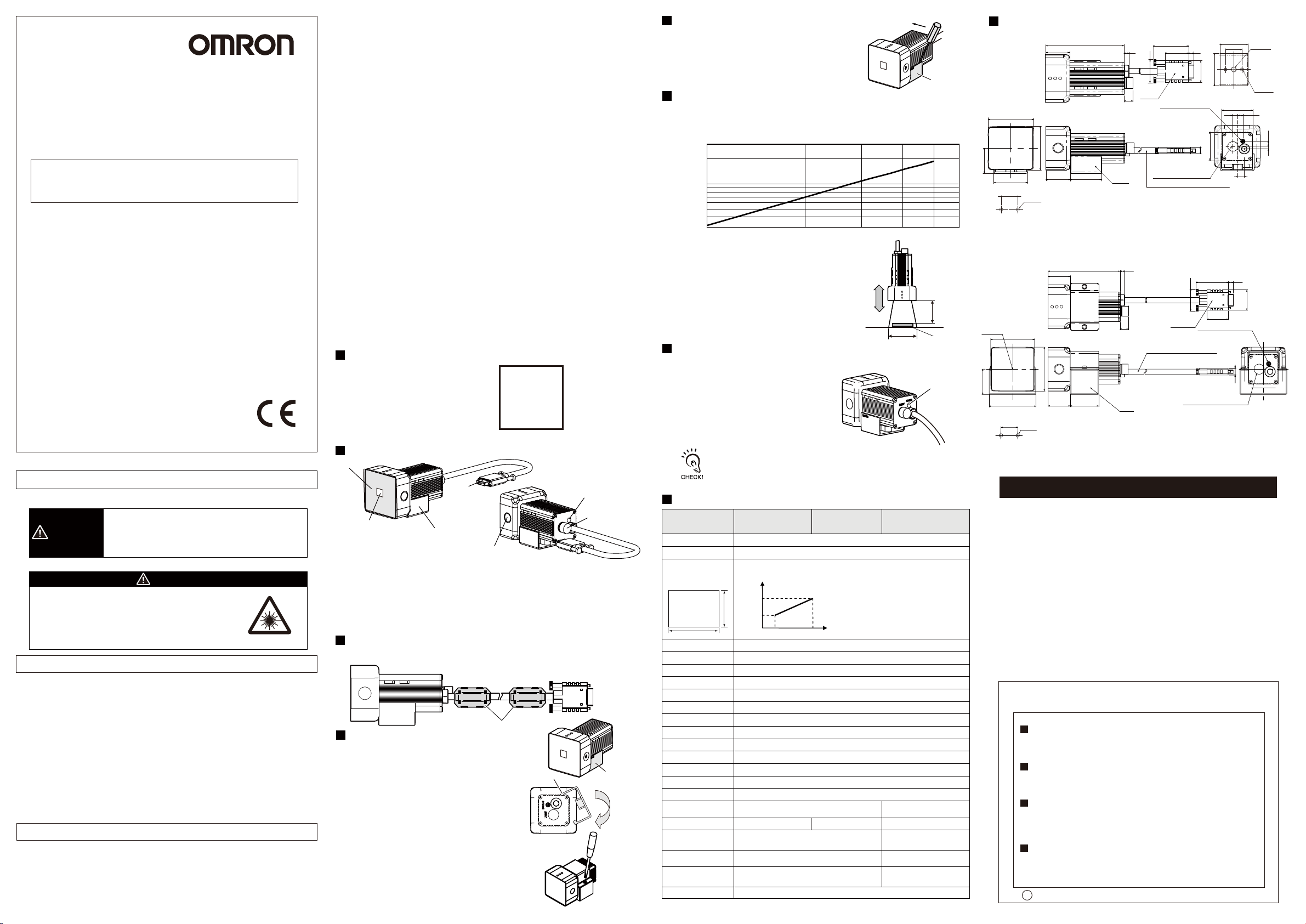
■外形寸法図
(ZFX-SC50/SC50W)
34
20
9.83
24.2
35.5
5
35.5
8
8
30.45
52.5
93
20 ±0.1
取付穴加工寸法
2-φ4.5
86
26.5
52.5
3426.5
5.6
9.8
注1.
注1.取付金具は各側面に取付可能
26.2
コネクタ
耐熱塩化ビニルシールドコード
φ6.2 標準長さ2m
38.14
5.925.34
ピント調整用ボリューム
外部照明用出力
(ZFX-SC50R)
52.03
光軸
取付穴加工寸法
20
±0.1
86
26.5
52.5
5.25
26.50
56
2-φ4.5
34
5.6
9.8
注1.
注1.取付金具は各側面に取付可能
2.62
38.14
コネクタ
耐熱塩化ビニルシールドコード
Ф6.2 標準長さ2m
外部照明用出力
5.9
25.34
ピント調整用ボリユーム
8
ご承諾事項
当社商品は、一般工業製品向けの汎用品として設計製造されています。従いまして、次に
掲げる用途での使用を意図しておらず、お客様が当社商品をこれらの用途に使用される際
には、当社は当社商品に対して一切保証をいたしません。ただし、次に掲げる用途であって
も当社の意図した商品用途の場合や特別の合意がある場合は除きます。
(a)高い安全性が必要とされる用途(例:原子力制御設備、燃焼設備、航空・宇宙設備、鉄
道設備、昇降設備、娯楽設備、医用機器、安全装置、その他生命・身体に危険が及び
うる用途)
(b)高い信頼性が必要な用途(例:ガス・水道・電気等の供給システム、24時間連続運転
システム、決済システムほか権利・財産を取扱う用途など)
(c)厳しい条件または環境での用途(例:屋外に設置する設備、化学的汚染を被る設備、
電磁的妨害を被る設備、振動・衝撃を受ける設備など)
(d)カタログ等に記載のない条件や環境での用途
*(a)から(d)に記載されている他、本カタログ等記載の商品は自動車(二輪車含む。以下同
じ)向けではありません。自動車に搭載する用途には利用しないで下さい。自動車搭載
用商品については当社営業担当者にご相談ください。
*上記は適合用途の条件の一部です。当社のベスト、総合カタログ、データシート等最新版
のカタログ、マニュアルに記載の保証・免責事項の内容をよく読んでご使用ください。
インダストリアルオートメーションビジネスカンパ ニー
●製品に関するお問い合わせ先
お客様相談室
クイック オムロン
0120-919-066
携帯電話・PHS・IP電話などではご利用いただけませんので、下記の電話番号へおかけください。
電話
055-982-5015
■営業時間:8:00〜21:00 ■営業日:365日
●FAXやWebページでもお問い合わせいただけます。
FAX055-982-5051/www.fa.omron.co.jp
●その他のお問い合わせ
納期・価格・サンプル・仕様書は貴社のお取引先、または貴社
担当オムロン販売員にご相談ください。
オムロン制御機器販売店やオムロン販売拠点は、Webページで
ご案内しています。
u
A
2013年9月
(通話料がかかります)
1/4-20
UNC深さ6
2-M4深さ6
(6.36)
(単位:mm)
2.42
(6.36)
3
Model
ZFX-SC50□
Smart Sensor
For Model ZFX-C□□
Sensor head unit
INSTRUCTION SHEET
Thank you for selecting OMRON product. This sheet primarily describes precautions required in installing and
operating the product.
Before operating the product, read the sheet thoroughly to
acquire sufficient knowledge of the product. For your convenience, keep the sheet at your disposal.
TRACEABILITY INFORMATION:
Representative in EU:
Omron Europe B.V.
Wegalaan 67-69
2132 JD Hoofddorp,
The Netherlands
NOTICE:
This product meets CISPR11 class A . The intended use of this product is in an
industrial environment only.
OMRON Corporation All Rights Reserved.
©
PRECAUTIONS ON SAFETY
●Meanings of Signal Words
Indicates a potentially hazardous situation which, if not
WARNING
●Alert Statements in this Sheet
Danger of damage to eyes
The ZFX-SC50□ emits visible light.
Do not stare into LED light directly. If the object
causes regular reflections, take care not to let the
reflected light enter your eyes.
PRECAUTIONS FOR SAFE USE
Please observe the following precautions for safe use of the products.
(1) Installation Environment
・ Do not use the product in environments where it can be exposed to inflammable /
explosive gas.
・ To secure the safety of operation and maintenance, do not install the product close
to high-voltage devices and power devices.
・ During installation, make sure that screws are tightened firmly.
(2) Power Supply and Wiring
・ High-voltage lines and power lines must be wired separately from this product.
Wiring them together or placing them in the same duct may cause induction,
resulting in malfunction or damage.
(3) Others
・ Do not attempt to dismantle, repair, or modify the product.
・ Dispose of this product as industrial waste.
・ If abnormal odors, heating, or smoke occurs, stop using the Smart Sensor
immediately, turn OFF the power, and consult with your OMRON representative.
PRECAUTIONS FOR CORRECT USE
Please observe the following precautions to prevent failure to operate, malfunctions,
or undesirable effects on product performance.
(1) Installation Site
Do not install the product in locations subjected to the following conditions.
・ Ambient temperature outside the rating
・ Rapid temperature fluctuations (causing condensation)
・ Relative humidity outside the range of 35 to 85%
・ Presence of corrosive or flammable gases
avoided, will result in minor or moderate injury, or may
result in serious injury or death. Additionally, there may
be significant property damage.
Manufacturer:
Omron Corporation,
Shiokoji Horikawa, Shimogyo-ku,
Kyoto 600-8530 JAPA N
Ayabe Factory
3-2 Narutani, Nakayama-cho,
Ayabe-shi, Kyoto 623-0105 JAPA N
2007-2009
WARNING
・ Presence of dust, salt, or iron particles
・ Direct vibration or shock
・ Reflection of intense light (such as other laser beams , electric arc welding machines
or ultraviolet rays)
・ Direct sunlight or near heaters
・ Water, oil, or chemical fumes or spray
・ Strong magnetic or electric field
(2) Power Supply and Wiring
・ Before connecting/disconnecting the Sensor Head, make sure that the Smart Sensor is
turned OFF. The Smart Sensor may break down if the Sensor Head is connected or
disconnected while the power is ON.
・ Use only combinations of Sensor Heads and Sensor Controllers specified in this sheet.
(3) Optical Axis and Detection Range
The center of the optical axis sometimes differs according to each Sensor Head. During
installation, be sure to check the center of the image and the detection range on the
LCD monitor of the Amplifier Unit.
(4) Ventilation Film
・ Do not peel off or probe the ventilation film with a sharp-pointed object.
If you so, the specifications of the protective structure may no longer be satisfied.
・ Do not block the ventilation film. Doing so might cause the front panel to be
con-densed.
(5) Focus Adjustment Control
Do not exert the torque of 5N・m or more as this might damage the control.
(6) Extra Light Connector
When you do not use extra light, put the connector cap on the connector.
Water-proof can not be assured without the cap.
(7) Maintenance and Inspection
・ Do not use thinner, benzene, acetone or kerosene to clean the Sensor Head and
Amplifier Unit.
・ If large dust particles adhere to the front Panel of the Sensor Head, use a blower
brush (used to clean camera lenses) to blow them off. Do not blow off the dust
particles with your mouth.
・ To remove smaller dust particles, wipe gently with a soft cloth.
Do not use excessive force to wipe off dust particles. Scratches on the front
Panel may cause errors.
(8) Installation Precautions
Tighter mounting screws at the torque specified.
Recommended screw tightening torque
M4:1.2N・m,
1/4”-20UNC:2.6N・m
Safety of LED
The product is considered to be classified
as Risk Group 1 by IEC62471.
Risk Group 1
IEC 62471
Part Names and Functions
(1) Lighting part
(5) Focus adjustment
control
(7) Extra Light
Connector
(2) Receiver part
(1) Lighting part
This section emits light.
(2) Receiver part
This section captures the
image.
(3) Connector
This connector is connected
to the Amplifier Unit.
(3) Connector
(4) Sensor Head
mounting fixture
(6) Ventilation film
(4) Sensor Head mounting fixture
This fixture is for mounting the Sensor Head.
This fixture can be mounted on all of the four
mounting surfaces.
(5) Focus adjustment control
This control is used for adjusting the focus of the image.
(6) Ventilation film
This film prevents the front panel from condensation.
(7) Extra Light Connector
This connector is connected to the Extra Light.
Attaching the ferrite core
Attach the ferrite core (provided with the Smart Sensor) to the case side and the
connector side of the Sensor Head.
Ferrite core
Installing the mounting fixture
Attach the mounting fixture (provided with the
Smart Sensor) to the side of the Sensor Head.
The mounting fixture can be installed on all of the
four mounting surfaces.
・ ZFX-SC50/SC50W
(1) Align the two hooks on one side of the mounting
fixture with the two grooves on the Sensor Head
body (light emitting side).
(2) Press in the other hook.
Push down until you hear it snap into place.
(3) Make sure that the mounting fixture is firmly
fixed on the Sensor Head.
・ ZFX-SC50R
(1) Align the boss of the base part(Black) and
groove of the Sensor Head body.
(2) Attach the bracket(Silver) to the base part.
(3) Fasten the screw(attached) and fix the parts.
Recommended torque value : 0.54 N・m
Hook
Mounting
fixture
Removal procedure
Insert a regular screwdriver into the gap (one of
the two gaps) between the mounting
fixture and the Sensor Head case, and remove the
mounting fixture.
Mounting
Installation distance
fixture
The following graphs show the relationship between detection range and setting
distance for each model of Sensor Head.
Values differ according to each model of Sensor Head, so fully check the model before
using these graphs.
300
100
L (mm)
Setting distance
30
10
Detection range
H (mm)
(Example)
When using a ZFX-SC50 Sensor Head at
a detection range of 20 mm required for
the location of the sensing object, the
setting distance of Sensor Head becomes
70mm.
Installation procedure
Detection range H
(1) Install the Sensor Head at the installation distance obtained in the above graphs.
(2) Turn the focus adjustment control
Setting
distance L
Workpiece
Focus
adjustment
control
to the left and right to adjust the focus.
Before turning the focus adjustment control slightly to the left and right, make sure that
the guide light is not at the upper or lower limit positions. The focus adjustment control
is a multi-turn control. However, the control stops turning at the upper or lower limit
positions. Do not exert unnecessary force to turn the control at the upper or lower limit
positions as this might damage the control.
Specifications
Item
Setting distance (L)
Detection range (H V)
Relation between setting
distance and detection range
Detection
range
H
Object lighting method
Object light source
Extra light interface
Sensing element
Shutter
Power supply voltage
Current consumption
Dielectric strength
Vibration resistance (destruction)
Shock resistance (destruction)
Ambient temperature
Ambient humidity
Ambient atmosphere
Connection method
Degree of protection
Materials
Weight
Accessories
LED Safety
31 to 187 mm
9.8×9.8 mm to 49×49 mm
V
Pulse lighting
Thirty six white LEDs
Available (ZFV-LT)
1/3-inch interline color CCD (reading all pixels)
Electronic shutter, shutter time: 1/170 to 1/20,000s
15 VDC, 48 VDC (Supplied from Amplifier Unit.)
Approx. 350 mA[15VDC:Approx. 150 mA, 48VDC:Approx. 200 mA](including Extra Light)
1,000 VAC, 50/60 Hz for 1 min
10 to 150 Hz, 0.35-mm single amplitude, 10 times each in X, Y, and Z directions for 8 min
150 m/s2 , three times each in six directions (up/down, left/right, forward/backward)
Operating: 0 to 40 ℃, Storage: -20 to 65 ℃ (with no icing or condensation)
Operating and storage: 35% to 85% (with no condensation)
Must be free of corrosive gas.
Prewired, Standard cable
length: 2 m
IEC60529, IP65
Case: ABS, Mounting bracket: PBT
Approx. 270 g
(including mounting bracket and cord)
Mounting bracket[model ZFV-XMF2](1), Ferrite core (2),
Instruction sheet
Risk Group 1 (IEC62471)
ZFX-SC50
(Standard View)
Setting
distance
(L)
187mm
31mm
10mm 50mm
ZFX-SC50W
(Standard View)
Detection
range
(H)
IEC60529, IP67
ZFX-SC50R
(Standard View)
Prewired,
Robot Cable length: 2 m
IEC60529, IP65
Case: ABS,
Mounting bracket(base):aluminum
Mounting bracket(bracket):stainless
Approx. 400 g
(including mounting bracket and cord)
Mounting bracket[model ZFV-XMF4](1),
Ferrite core (2), Instruction sheet
(ZFX-SC50/SC50W)
30.45
MOUNTING SCREW HOLES
60
(ZFX-SC50R)
OPTICAL AXIS
52.03
MOUNTING SCREW HOLES
Dimensions
1/4-20
34
UNC DEPTH 6
20
9.83
2-M4
DEPTH 6
35.5
(6.36)
5
35.5
38.14
25.34
(6.36)
3
8
5.9
2.42
8
(Unit : mm)
52.5
20±0.1
20±0.1
86
26.5
52.5
93
2-4.5Dia.
52.5
5.25
56
2-4.5Dia.
3426.5
86
26.5
26.50
34
5.6
9.8
NOTE 1.
NOTE 1. ATTACHMENT ON EACH SIDE IS POSSIBLE FOR MOUNTING BRACKET.
5.6
9.8
NOTE1.
38.14
26.2
CONNECTOR
FOCUS ADJUSTMENT VOLUME
OUTPUT FOR EXTERNAL LIGHTING
HEAT-RESISTANT VINYL CHLORIDE SHIELD CORD
6.2 Dia. STANDARD LENGTH 2m
HEAT-RESISTANT VINYL CHLORIDE SHIELD CORD
6.2 Dia. STANDARD LENGTH 2m
NOTE1.ATTACHMENT ON EACH SIDE IS POSSIBLE FOR MOUNTING BRACKET.
5.925.34
24.2
8
2.62
CONNECTOR
FOCUS ADJUSTMENT VOLUME
OUTPUT FOR EXTERNAL LIGHTING
Suitability for Use
Omron Companies shall not be responsible for conformity with any standards,
codes or regulations which apply to the combination of the Product in the
Buyer’s application or use of the Product. At Buyer’s request, Omron will
provide applicable third party certification documents identifying ratings and
limitations of use which apply to the Product. This information by itself is not
sufficient for a complete determination of the suitability of the Product in
combination with the end product, machine, system, or other application or
use. Buyer shall be solely responsible for determining appropriateness of the
particular Product with respect to Buyer’s application, product or system.
Buyer shall take application responsibility in all cases.
NEVER USE THE PRODUCT FOR AN APPLICATION INVOLVING
SERIOUS RISK TO LIFE OR PROPERTY WITHOUT ENSURING THAT THE
SYSTEM AS A WHOLE HAS BEEN DESIGNED TO ADDRESS THE RISKS,
AND THAT THE OMRON PRODUCT(S) IS PROPERLY RATED AND
INSTALLED FOR THE INTENDED USE WITHIN THE OVERALL
EQUIPMENT OR SYSTEM.
See also Product catalog for Warranty and Limitation of Liability.
OMRON Corporation
Tokyo, JAPAN
Regional Headquarters
OMRON EUROPE B.V.
Sensor Business Unit
Carl-Benz-Str. 4, D-71154 Nufringen, Germany
Tel: (49) 7032-811-0/Fax: (49) 7032-811-199
OMRON ELECTRONICS LLC
One Commerce Drive Schaumburg,
IL 60173-5302 U.S.A.
Tel: (1) 847-843-7900/Fax: (1) 847-843-7787
OMRON ASIA PACIFIC PTE. LTD.
No. 438A Alexandra Road # 05-05/08 (Lobby 2),
Alexandra Technopark,
Singapore 119967
Tel: (65) 6835-3011/Fax: (65) 6835-2711
OMRON (CHINA) CO., LTD.
Room 2211, Bank of China Tower,
200 Yin Cheng Zhong Road,
PuDong New Area, Shanghai, 200120, China
Tel: (86) 21-5037-2222/Fax: (86) 21-5037-2200
r
Sep, 2013
D
Industrial Automation Company
Contact: www.ia.omron.com
 Loading...