

Omron ZFX-SC150, ZFX-SC150R, ZFX-SC150W Instruction Sheet
形
ZFX-SC150
スマートセンサ
形ZFX-C□□用
センサ ヘッド
取扱説明書
□
4.通気膜について
・通気膜をはがしたり、先の尖ったものでつついたりしない でください 。
保護構造を満足できなくなるおそれ があります 。
・通気膜はふさがないでください 。センサ ヘッド前面 のパネル が 曇るおそれがあります 。
5.保守点検について
・センサヘッドやアンプユ ニットの清掃には、シンナ ー 、アルコール、ベンジン、アセトン、灯油
類は使用しないでください 。
・センサヘッド前 面 の パネルに、大きなゴミやホコリが付いた場合は、ブロアブラシ ( カメラ
レンズ 用 ) で 吹き飛 ばしてください 。呼 気 で 吹き飛 ばすことは避けてください 。
・小さなゴミやほこりは、柔らかい布で丁寧にふきとってください 。強くふくことは避 けてくだ
さい 。キズが つくと、誤検出の原因になります 。
6.設置に関するご注意
取付けねじは、規定のトルクで締め付けてください 。
推奨締付けトルク M4:1.2N・m,1/4-20UNC:2.6N・m
■各部の名称と機能
(1)照明部
(3)コネクタ
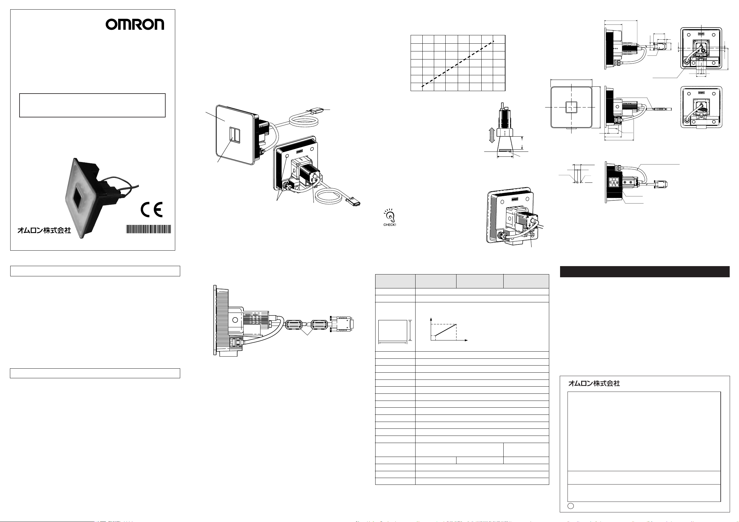
■設置距離
次のグラフは検出範囲と設置距離の関係を表したものです。センサ ヘッドの形 式ごとに 値
は異なりますので、形式を十分ご確認の上、グラフをご 覧ください 。
240
180
設置距離L[mm]
100
80 120 160
検出範囲H[mm]
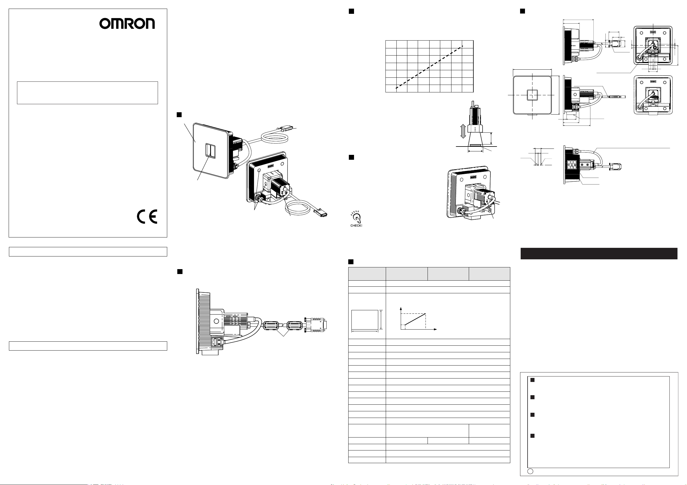
■外形寸法図
140
140
110.2
59.5
耐熱塩化ビニルシールドコード
φ6.2 標準長さ2m
38.14
25.34
26.2
コネクタ
ピント調整用ボリュー ム
5.9
8.5
24.2
8.5 7
33
8
4
8.5
73.2
このたびは 、本製品をお買い上げいただきまして、まことにありがとうござ います 。
ご使用に際しては、次の内容をお守りください 。
・電気の知識を有する専門家がお取り扱いください。
この取扱説明書をよくお読みになり、十分にご理解のうえ、正しくご使用ください。
・
・この取扱説明書はいつでも参照できるよう大切に保管してください 。
*1846304- 5F*
OMRON Corporation
©
2007-2009
All Rights Reserved.
安全上の要点
以下に示すような項目は安全を確保する上で必要なことですので必ず守ってください 。
1. 設置環境について
・引火性、爆発 性ガスの環境では使用しないでください 。
・操作や保守の安全を確保するため、高電圧機器や動力機器から離して設置してくださ
い。
・取付けにおいて、ねじの締め付けは確実に行ってください 。
2. 電源および配線について
・高圧線、動力線と当製品の配線は別配線としてください 。同一配線あるいは同一ダクトにす
ると誘 導を受け、誤動作あるいは破損の原因になることがあります 。
3. その他
・本製品を分解したり、修理、改造したりしないでください 。
・廃棄するときは、産業廃棄物として 処 理してください 。
・異臭がする、本体が非常に熱くなる、煙が出るなどの異常が起こった場合、すぐに 使 用を
中止し、電源を切った状態で当社支店・営業所までご相談ください 。
使用上の注意
製品が動作不能、誤動作、または 性 能・機器への悪影響を防ぐため、
以下のことを守ってください 。
1.設置場所について
次のような場 所には設 置しないでください 。
・周囲温度が定格の範囲を越える場所
・温度変化が急激な場所(結露する場所)
・相対湿度が 35 〜 85%RH の範囲を超える場所
・腐食性ガス、可燃性ガスがある場所
・塵埃、塩分、鉄粉がある場所
・振動や衝撃が直接加わる場所
・強い外乱光(レーザ光 、アーク溶接光、紫外光など)があたる場所
・直射日光があたる場所や暖房器具のそば
・水・油・化学薬品の飛沫がある場所
・強磁界、強電界がある場所
2.電源および接続、配線について
・センサヘッドの着脱は、必ず電源を切った状態で行ってください 。電源 ON のまま行う
と故障の原因になります 。
・センサヘッドとアンプ ユ ニットは、取扱説明書で指定した組合せで使用してください 。
3.光軸、検出範 囲について
光軸中心はセンサヘッドごとに ばらつくことがあります の で 、取付けるときは 必 ずアンプ
ユニットの液晶モニタで画像の中心と検出範囲を確認してください 。
(2)受光部
(1)照明部
LED照明部です。
(2)受光部
画像を取込みます。
(5)通気膜
(4)ピント調 整 ボリューム
画像のピントを調 整をするときに使 用します 。
(5)通気膜
前面パネルの曇りを防 止します。
(4)ピント調整
ボリューム
(3)コネクタ
アンプ ユニットに接続します。
■フェライトコア の 装 着
センサ ヘッドの本体側およびコネクタ側にフェライトコア(付属品)を装着してください 。
フェライトコア
(例)
計測対象箇所に必要な検出範囲が
125mmで形ZFX-SC150のセンサヘッド
を使用する場合、センサ ヘッド設置距離
は180mmとなります 。
検出範囲(H)
■設置手順
(1)光学図表から読取った設置距離にセンサヘッドを設置します。
(2)ピント調 整 ボリュームを左右に回してピントを合わせます。
ピント調 整ボリューム は 多 回 転 ボリュー ム になって い
ますが 、ピントが一番近い側(右回転)では 回 転 が
止まります。故障の原因となりますので、無理にボ
リュー ム を 回 さな い でください。(ピントが 一 番 遠 い 側
(左回転)では空回りします 。)
■定格/性能
項 目
設置距離(L)
検出範囲(H×V)
検出範囲と
設置距離の関係
検出範囲
H
ワーク照明点灯方式
ワーク照明用光源
オプション照明I/F
撮像素子
シャッタ機能
電源電圧
消費電流
耐電圧
振動(耐久)
衝撃(耐久)
周囲温度
周囲湿度
周囲雰囲気
接続方式
保護構造
材質
質量
付属品
形ZFX-SC150
(超広視野タイプ)
115mm〜227mm(可変)
89×89mm〜148×148mm(可変)
設置距離
(L)
227mm
V
115mm
89mm 148mm
パルス点灯
白色発光ダイオード×72個
なし
全画素読出し方式インターライン転送型 1/3インチCCD(カラー)
シャッタ時間:1/170〜1/20000s
DC15V、DC48V(アンプユニットより供給)
約350mA[15V:約150mA、48V:約200mA]
AC1000V50Hz/60Hz1分間
10〜150Hz片振幅0.35mmX/Y/Z方向各8分10回
2
6方向(上下、左右、前後)各3回
150m/s
動作時:0〜+40℃保存時:−20〜+65 ℃(ただし氷結、結露しないこと)
動作時・保存時:各35〜85%RH(ただし、結露しないこと)
腐食性ガスのないこと
コード引き出しタイプ
(標準コード2m)
IEC60529規格IP65 IEC60529規格IP67
ケース:ABS
約600g(コード含む)
フェライトコア2個、取扱説明書(本紙)
形ZFX-SC150W
(超広視野タイプ)
検出範囲
(H)
検出距離(L)
ワーク
ピント調 整
ボリューム
形ZFX-SC150R
(超広視野タイプ)
コード引き出しタイプ
(耐屈曲コード2m)
IEC60529規格IP65
35
57
取付面
98
2-M4深さ6
U1/4-20UNC深さ5
耐熱・耐油性塩化ビニルシールドコード
φ5mm 標準長さ200mm
(単位:mm)
10 10
U1/4-20UNC
取付穴加工寸法
12
20±0.1
2-φ4.5
ご使用に際してのご承諾事項
①安全を確保する目的で直接的または間接的に人体を検出する用途に、本製品を使用し
ないでください 。同用途には、当社センサカタログに掲載している安全センサをご使用く
ださい 。
②下記用途に使用される場合、当社営業担当者までご相談のうえ仕様書などによりご確
認いただくとともに、定格・性能に対し余裕を持った使い方や、万一故障があっても危険
を最小にする安全回路などの安全対策を講じてください 。
a)屋外の用途、潜在的な化学的汚染あるいは電気的妨害を被る用途
またはカタログ 、取扱説明書等に記載のない条件や環境での使用
b)原子力制御設備、焼却設備、鉄道・航空・車両設備、医用機械、娯楽機械、
安全装置、および行政機関や個別業界の規制に従う設備
c)人命や財産に危険が及びうるシス テ ム・機械・装置
d)ガス、水道、電気の供給システムや24時間連続運転システムなどの
高い信頼性が必要な設備
e)その他、上記a)〜d)に準ずる、高度な安全性が必要とされる用 途
*上記は適合用途の条件の一部です。当社のベスト、総合カタログ・データシート等最新版
のカタログ、マニュアルに記載の保証・免責事項の内容をよく読んでご 使 用ください 。
●お問い合わせ先
カスタマサポートセンタ
フリーコ ー ル
携帯電話・PHSなどではご利用いただけませんので、その場合は下記電話番号へおかけください 。
電話
055-982-5015
〔技術のお問い合わせ時間〕
■
営業時間:8:00〜21:00
■営 業 日:365日
■上記フリ−コ−ル以外のセンシング機器の技術窓口:
電話
055-982-5002
〔営業のお問い合わせ時間〕
■
営業時間:9:00〜12:00/13:00〜17:30(土・日・祝祭日は休業)
■営 業 日:土・日・祝祭日/春期・夏期・年末年始休暇を除く
●FAXによるお問い合わせは下記をご利用ください 。
カスタマサポートセンタ お客様相談室 FAX055-982-5051
●その他のお問い合わせ先
納期・価格・修理・サンプル・仕様書は貴社のお取引先、
または貴社担当オムロン営業員にご相談ください 。
q
2009年10月
インダ ストリア ル オ ートメーションビジネスカンパニー
0120-919-066
(通話料がかかります )
(通話料がかかります )
Model
ZFX-SC150
□
Smart Sensor
For Model ZFX-C□□
Sensor head unit
INSTRUCTION SHEET
Thank you for selecting OMRON product. This sheet primarily describes precautions required in installing and
operating the product.
Before operating the product, read the sheet thoroughly to
acquire sufficient knowledge of the product. For your convenience, keep the sheet at your disposal.
TRACEABILITY INFORMATION:
Representative in EU:
Omron Europe B.V.
Wegalaan 67-69
2132 JD Hoofddorp,
The Netherlands
NOTICE:
This product meets CISPR11 class A . The intended use of this product is in an
industrial environment only.
OMRON Corporation All Rights Reserved.
©
PRECAUTIONS FOR SAFE USE
Please observe the following precautions for safe use of the products.
(1) Installation Environment
・ Do not use the product in environments where it can be exposed to inflammable /
explosive gas.
・ To secure the safety of operation and maintenance, do not install the product close
to high-voltage devices and power devices.
・ During installation, make sure that screws are tightened firmly.
(2) Power Supply and Wiring
・ High-voltage lines and power lines must be wired separately from this product.
Wiring them together or placing them in the same duct may cause induction,
resulting in malfunction or damage.
(3) Others
・ Do not attempt to dismantle, repair, or modify the product.
・ Dispose of this product as industrial waste.
・ If abnormal odors, heating, or smoke occurs, stop using the Smart Sensor
immediately, turn OFF the power, and consult with your OMRON representative.
PRECAUTIONS FOR CORRECT USE
Please observe the following precautions to prevent failure to operate, malfunctions,
or undesirable effects on product performance.
(1) Installation Site
Do not install the product in locations subjected to the following conditions.
・ Ambient temperature outside the rating
・ Rapid temperature fluctuations (causing condensation)
・ Relative humidity outside the range of 35 to 85%
・ Presence of corrosive or flammable gases
・ Presence of dust, salt, or iron particles
・ Direct vibration or shock
・ Reflection of intense light (such as other laser beams , electric arc welding machines
or ultraviolet rays)
・ Direct sunlight or near heaters
・ Water, oil, or chemical fumes or spray
・ Strong magnetic or electric field
(2) Power Supply and Wiring
・ Before connecting/disconnecting the Sensor Head, make sure that the Smart Sensor
is turned OFF. The Smart Sensor may break down if the Sensor Head is connected
or disconnected while the power is ON.
・ Use only combinations of Sensor Heads and Sensor Controllers specified in this
sheet.
(3) Optical Axis and Detection Range
The center of the optical axis sometimes differs according to each Sensor Head.
During installation, be sure to check the center of the image and the detection range
on the LCD monitor of the Amplifier Unit.
Manufacturer:
Omron Corporation,
Shiokoji Horikawa, Shimogyo-ku,
Kyoto 600-8530 JAPAN
Ayabe Factory
3-2 Narutani, Nakayama-cho,
Ayabe-shi, Kyoto 623-0105 JAPAN
2007-2009
(4) Ventilation Film
・ Do not peel off or probe the ventilation film with a sharp-pointed object.
If you so, the specifications of the protective structure may no longer be satisfied.
・ Do not block the ventilation film. Doing so might cause the front panel to be
con-densed.
(5) Maintenance and Inspection
・ Do not use thinner, benzene, acetone or kerosene to clean the Sensor Head and
Amplifier Unit.
・ If large dust particles adhere to the front Panel of the Sensor Head, use a blower
brush (used to clean camera lenses) to blow them off. Do not blow off the dust
particles with your mouth.
・ To remove smaller dust particles, wipe gently with a soft cloth.
Do not use excessive force to wipe off dust particles. Scratches on the front
Panel may cause errors.
(6) Installation Precautions
Tighter mounting screws at the torque specified.
Recommended screw tightening torque
M4:1.2N・m,
1/4”-20UNC:2.6N・m
Part Names and Functions
(1) Lighting part
(3) Connector
(2) Receiver part
(1) Lighting part
This section emits light.
(5) Ventilation film
(4) Focus adjustment
control
(2) Receiver part
This section captures the
image.
(3) Connector
This connector is connected
to the Amplifier Unit.
(4) Focus adjustment control
This control is used for adjusting the focus of the image.
(5) Ventilation film
This film prevents the front panel from condensation.
Attaching the ferrite core
Attach the ferrite core (provided with the Smart Sensor) to the case side and the
connector side of the Sensor Head.
Ferrite core
Installation distance
The following graphs show the relationship between detection range and setting
distance for each model of Sensor Head.
Values differ according to each model of Sensor Head, so fully check the model before
using these graphs.
240
180
L (mm)
Setting distance
100
80 120 160
Detection range
H (mm)
(Example)
When using a ZFX-SC150 Sensor Head
at a detection range of 125 mm required
for the location of the sensing object, the
setting distance of Sensor Head becomes
180mm.
Installation procedure
Detection range H
Setting
distance L
Workpiece
(1) Install the Sensor Head at the installation
distance obtained in the above graphs.
(2) Turn the focus adjustment control
to the left and right to adjust the focus.
Before tuning the focus adjustment control
slightly to the right, make sure that the guide
mark is not at the lower limit position.
The focus adjustment control is a multi-turn
control. However, the control stops turning at
the lower limit position (right turn).
The control turns idle even after the upper limit position (left turn).
Do not exert unnecessary force to turn the control at the upper or
lower limit positions as this might damage the control.
Focus
adjustment
control
Specifications
Item
Setting distance (L)
Detection range (H V)
Relation between setting
distance and detection range
Detection
range
H
Object lighting method
Object light source
Extra light interface
Sensing element
Shutter
Power supply voltage
Current consumption
Dielectric strength
Vibration resistance (destruction)
Shock resistance (destruction)
Ambient temperature
Ambient humidity
Ambient atmosphere
Connection method
Degree of protection
Materials
Weight
Accessories
115 to 227 mm
89×89 mm to 148×148 mm
227mm
V
115mm
Pulse lighting
Seventy two white LEDs
Not available
1/3-inch interline color CCD (reading all pixels)
Electronic shutter, shutter time: 1/170 to 1/20,000s
15 VDC, 48 VDC (Supplied from Amplifier Unit.)
Approx. 350 mA[15VDC:Approx. 150 mA, 48VDC:Approx. 200 mA]
1,000 VAC, 50/60 Hz for 1 min
10 to 150 Hz, 0.35-mm single amplitude, 10 times each in X, Y, and Z directions for 8 min
150 m/s2 , three times each in six directions (up/down, left/right, forward/backward)
Operating: 0 to 40 ℃, Storage: -20 to 65 ℃ (with no icing or condensation)
Operating and storage: 35% to 85% (with no condensation)
Must be free of corrosive gas.
Case: ABS
Approx. 600 g (including cord)
Ferrite core (2), Instruction sheet
ZFX-SC150
(Ultra-wide View)
Setting
distance
(L)
89mm 148mm
Prewired, Standard cable
length: 2 m
IEC60529, IP65 IEC60529, IP67
ZFX-SC150W
(Ultra-wide View)
Detection
range
(H)
ZFX-SC150R
(Ultra-wide View)
Prewired, Crooked-proof cable
length: 2 m
IEC60529, IP65
Dimensions
110.2
59.5
38.14
25.34
5.9
26.2
140
10 10
U1/4-20UNC
MOUNTIONG SCREW HOLES
20±0.1
2-4.5Dia.
HEAT-RESISTANT VINYL CHLORIDE SHIELD CODE
6.2 Dia. STANDARD LENGTH 2m
140
12
35
57
98
FOCUS ADJUSTMENT VOLUME
MOUNTING
SURFACE
HEAT-RESISTANT・OIL-RESISTANT VINYL CHLORIDE SHIELD CODE
5 Dia. STANDARD LENGTH 200m
2-M4 DEPTH 6
U1/4-20UNC DEPTH 5
Suitability for Use
THE PRODUCTS CONTAINED IN THIS SHEET ARE NOT SAFETY RATED.
THEY ARE NOT DESIGNED OR RATED FOR ENSURING SAFETY OF
PERSONS, AND SHOULD NOT BE RELIED UPON AS A SAFETY
COMPONENT OR PROTECTIVE DEVICE FOR SUCH PURPOSES.
Please refer to separate catalogs for OMRON's safety rated products.
OMRON shall not be responsible for conformity with any standards, codes, or
regulations that apply to the combination of the products in the customer's
application or use of the product.
Take all necessary steps to determine the suitability of the product for the
systems, machines, and equipment with which it will be used.
Know and observe all prohibitions of use applicable to this product.
NEVER USE THE PRODUCTS FOR AN APPLICATION INVOLVING
SERIOUS RISK TO LIFE OR PROPERTY WITHOUT ENSURING THAT THE
SYSTEM AS A WHOLE HAS BEEN DESIGNED TO ADDRESS THE RISKS,
AND THAT THE OMRON PRODUCT IS PROPERLY RATED AND
INSTALLED FOR THE INTENDED USE WITHIN THE OVERALL
EQUIPMENT OR SYSTEM.
See also Product catalog for Warranty and Limitation of Liability.
EUROPE
OMRON EUROPE B.V. Sensor Business Unit
Carl-Benz Str.4, D-71154 Nufringen Germany
Phone:49-7032-811-0 Fax: 49-7032-811-199
NORTH AMERICA
OMRON ELECTRONICS LLC
One Commerce Drive Schaumburg,IL 60173-5302 U.S.A.
Phone:1-847-843-7900 Fax : 1-847-843-7787
ASIA-PACIFIC
OMRON ASIA PACIFIC PTE. LTD.
No. 438A Alexandra Road #05-05-08(Lobby 2),
Alexandra Technopark, Singapore 119967
Phone : 65-6835-3011 Fax :65-6835-2711
CHINA
OMRON(CHINA) CO., LTD.
Room 2211, Bank of China Tower,
200 Yin Cheng Zhong Road,
PuDong New Area, Shanghai, 200120, China
Phone : 86-21-5037-2222 Fax :86-21-5037-2200
OMRON Corporation
o
OCT, 2009
CONNECTOR
8.5
24.2
8.5 7
33
8
(Unit : mm)
4
8.5
73.2
 Loading...