

Page 1

Cat. No. Z265-E1-05
Smart Sensor
ZFX-C
Serial Communication
COMMAND REFERENCE
Page 2
Introduction
Thank you for purchasing the ZFX-C.
This manual provides information regarding functions, performance and operating methods that
are required for using the ZFX-C.
When using the ZFX-C, be sure to observe the following:
• The ZFX-C must be operated by personnel knowledgeable in electrical engineering.
• To ensure correct use, please read this manual thoroughly to deepen your understanding of the
product.
• Please keep this manual in a safe place so that it can be referred to whenever necessary.
Manuals Provided with this Product
Smart Sensor
Vision Sensor with built-in LCD monitor
ZFX-C
User's Manual
Smart Sensor
Vision Sensor with built-in LCD monitor
ZFX-C
Serial Communication
Command Reference
Cat. No.
XXXX-XX-XX
Cat. No.
XXXX-XX-XX
User's Manual
This manual describes basic operations, such as
installation and connections, and information on settings
and specifications to ensure safe and correct use of this
product.
Serial Communication Command
Reference (this document)
This manual provides reference information for when this
product performs communications with an external
device, such as a PC or a programmable controller, via
the serial interface.
Page 3

Contents
Communication Interface Specifications . . . . . . . . . . . . . . . . . . . . . . . . . . 3
Connection. . . . . . . . . . . . . . . . . . . . . . . . . . . . . . . . . . . . . . . . . . . . . . . . . . . 4
Connecting a PC . . . . . . . . . . . . . . . . . . . . . . . . . . . . . . . . . . . . . . . . . . . . . . . . . . . 4
Connecting a PLC . . . . . . . . . . . . . . . . . . . . . . . . . . . . . . . . . . . . . . . . . . . . . . . . . . 6
About Communication Commands . . . . . . . . . . . . . . . . . . . . . . . . . . . . . . . 7
Command/Response Format. . . . . . . . . . . . . . . . . . . . . . . . . . . . . . . . . . . . . . . . . . 7
Available Commands . . . . . . . . . . . . . . . . . . . . . . . . . . . . . . . . . . . . . . . . . . . . . . . 10
Bank Control Commands . . . . . . . . . . . . . . . . . . . . . . . . . . . . . . . . . . . . . . . . . . . . 12
Measurement Control/Measurement Value Acquisition Commands . . . . . . . . . . . 14
Setting Acquisition/Change Commands . . . . . . . . . . . . . . . . . . . . . . . . . . . . . . . . 17
Backup/Restore Commands . . . . . . . . . . . . . . . . . . . . . . . . . . . . . . . . . . . . . . . . . 25
Utility Commands. . . . . . . . . . . . . . . . . . . . . . . . . . . . . . . . . . . . . . . . . . . . . . . . . .35
Parameter List . . . . . . . . . . . . . . . . . . . . . . . . . . . . . . . . . . . . . . . . . . . . . . . . . . . . 39
Example of Usage . . . . . . . . . . . . . . . . . . . . . . . . . . . . . . . . . . . . . . . . . . . . 56
Version Upgrade Information. . . . . . . . . . . . . . . . . . . . . . . . . . . . . . . . . . . 60
Revision History . . . . . . . . . . . . . . . . . . . . . . . . . . . . . . . . . . . . . . . . . . . . . 64
ZFX-C Serial Communication Command Reference
1
Page 4

■ Difference between the ZFX-C20/C25, ZFX-C10H/C15H and ZFX-C10/C15
This manual is intended for the ZFX-C20/C25, ZFX-C10H/C15H and ZFX-C10/C15 Controllers.
Unless otherwise specified, explanations are given for the ZFX-C20/C25. The following table summarizes the
main differences.
Item ZFX-C20/C25 ZFX-C10H/C15H ZFX-C10/C15
Number of connected cameras 2 1 1
Available measurement items All available Only the following items are available:
Pattern search
Sensitive search
Area
Position
Width
Count
Bright
Hue
Defect
Available position correction items All available Only the following items are available:
Edge position
Area
1 model
2 model
Number of measurement items that
can be measured simultaneously
Logging monitor function Available Not available
Max. 128 items/bank Max. 32 items/bank
2
ZFX-C Serial Communication Command Reference
Page 5
Communication Interface Specifications
You can use the USB port or RS-232C/422 connector of the Controller to perform serial communication with
external devices such as a personal computer or programmable controller.
Serial communication functions in the RUN mode. Communication cannot be performed in the ADJ or MENU
modes.
<USB>
This interface allows Full speed (12 Mbps) communications compliant with USB2.0 with a PC equipped with
the same USB interface.
Synchronization method Start-stop
Transmission code ASCII (Binary format can be selected only when outputting measurement values set at
[Setup] - [Support] - [Calculation] - [Data].)
Communication speed USB2.0-compliant
Data length -
Parity -
Stop bit -
Delimiter CR, LF, CR+LF
Transmission protocol Normal (Note, however, that XMODEM protocol is used when sending image data, system
data and other data.)
<RS-232C/422>
This interface allows data communications compliant with the EIA RS-232C/422 standards up to a maximum
speed of 115200 bps.
Synchronization method Start-stop
Transmission code ASCII (Binary format can be selected only when outputting measurement values set at
[Setup] - [Support] - [Calculation] - [Data].)
Communication speed 9600, 19200, 38400, 57600, 115200
Data length 7 bits, 8 bits
Parity None, even, odd
Stop bit 1 bit, 2 bits
Delimiter CR, LF, CR+LF
Transmission protocol Normal (Note, however, that XMODEM protocol is used when sending image data, system
data and other data.)
For details on how to set the communication specifications, refer to the User's Manual.
<Ethernet>
Communication protocol TCP/IP
Transmission mode Peer to Peer
ZFX-C Serial Communication Command Reference
Communication Interface Specifications
3
Page 6
Connection
Ferrite cores
Note
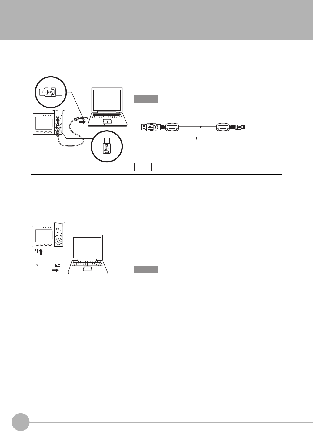
Connecting a PC
<USB>
Use a USB cable (ZFX-XUSB) to connect the Controller to the
PC.
Important
• When connecting the PC, refer to the Instruction Manual for the PC.
• Attach the ferrite cores supplied to both ends of the USB cable.
Installation of the USB driver is necessary only when connecting an external device to the USB interface for the first
time.
For the USB driver, please contact your OMRON representative.
<Ethernet>
Use a commercially available LAN cable to connect the Controller
to the PC.
There are two ways of making the LAN connection to the PC,
directly to the PC or via a hub.
Important
The following communications are not possible:
• Communications with the Controller from outside the LAN
• Communications between the Controller and two or more PCs
• Communications between Controllers
• Communications between the Controller and the PLC
4
Connection
ZFX-C Serial Communication Command Reference
Page 7
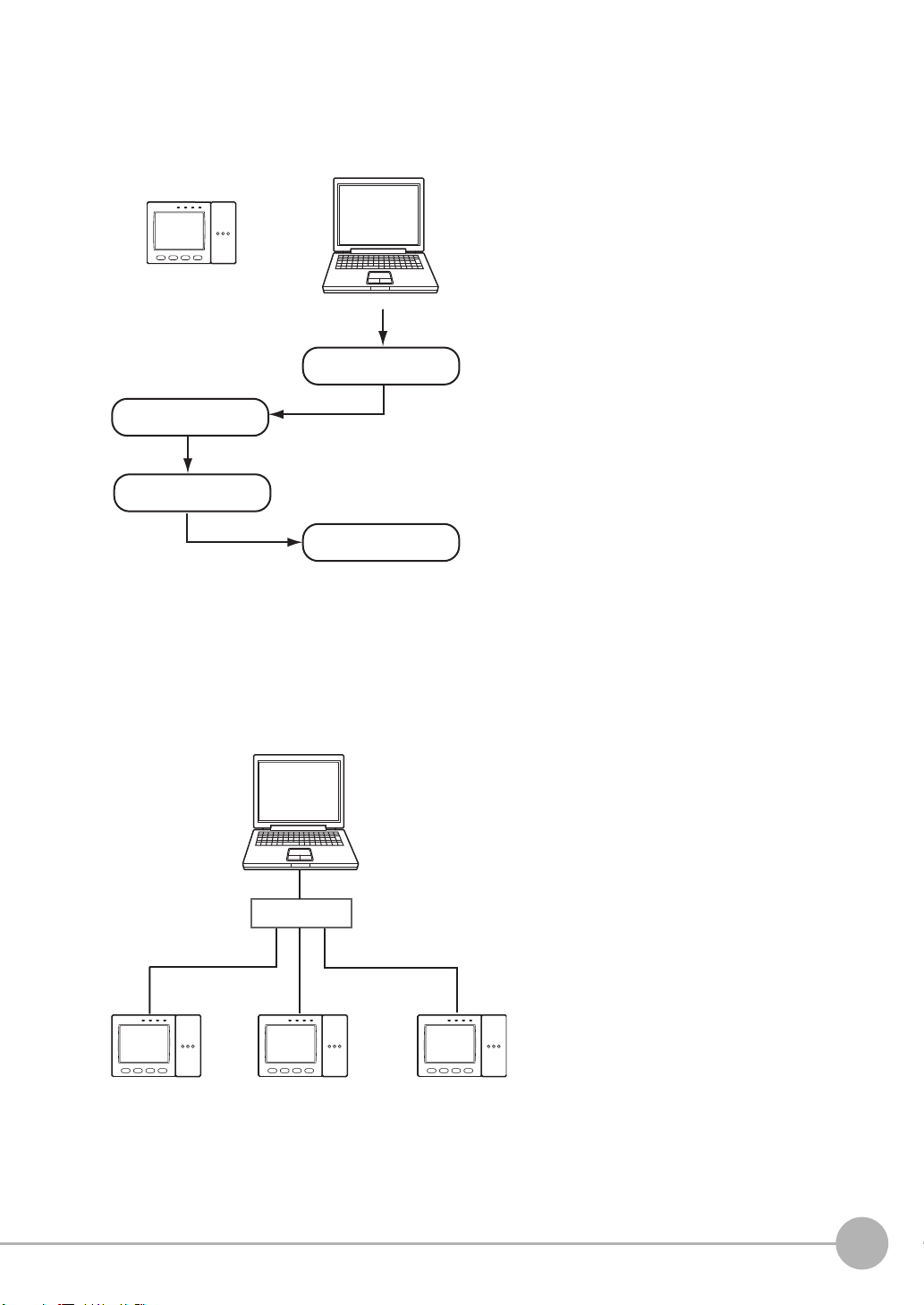
• 1:1 Connection
If communications software for a TELNET
connection is activated on the PC to access the
Controller, the Controller will automatically switch to
the Ethernet connection.
The parallel interface's ENABLE signal will be OFF during measurement.
To end the Ethernet connection, input the
EXIT command.
Input command.
Execute
measurement.
Output the
processing result.
Receive the
measurement result.
MEASURE
IP address
192.168.250.010
Start the TELNET communications software on the PC, and
specify individual IP addresses to access each Controller.
The method for inputting commands is the same as for a 1:1
connection.
HUB
IP address
192.168.250.100
IP address
192.168.250.101
IP address
192.168.250.102
When connecting the Controller directory to the PC, use a 10BASE-T or 100BASE-TX cross cable (Category 5
or higher). Limit the cable length to 30 m.
Example: A measurement command is input and the result is acquired.
• 1:N Connection
When connecting two or more Controllers to one PC via a hub, use a 10BASE-T or 100BASE-TX straight cable
(Category 5 or higher). Also, limit the cable lengths between the PC and the hub, and the Controllers and the
hub to 30 m, respectively. Be sure to set unique IP addresses to each Controller. Do not set duplicate IP
addresses to Controllers.
Example:
ZFX-C Serial Communication Command Reference
Connection
5
Page 8
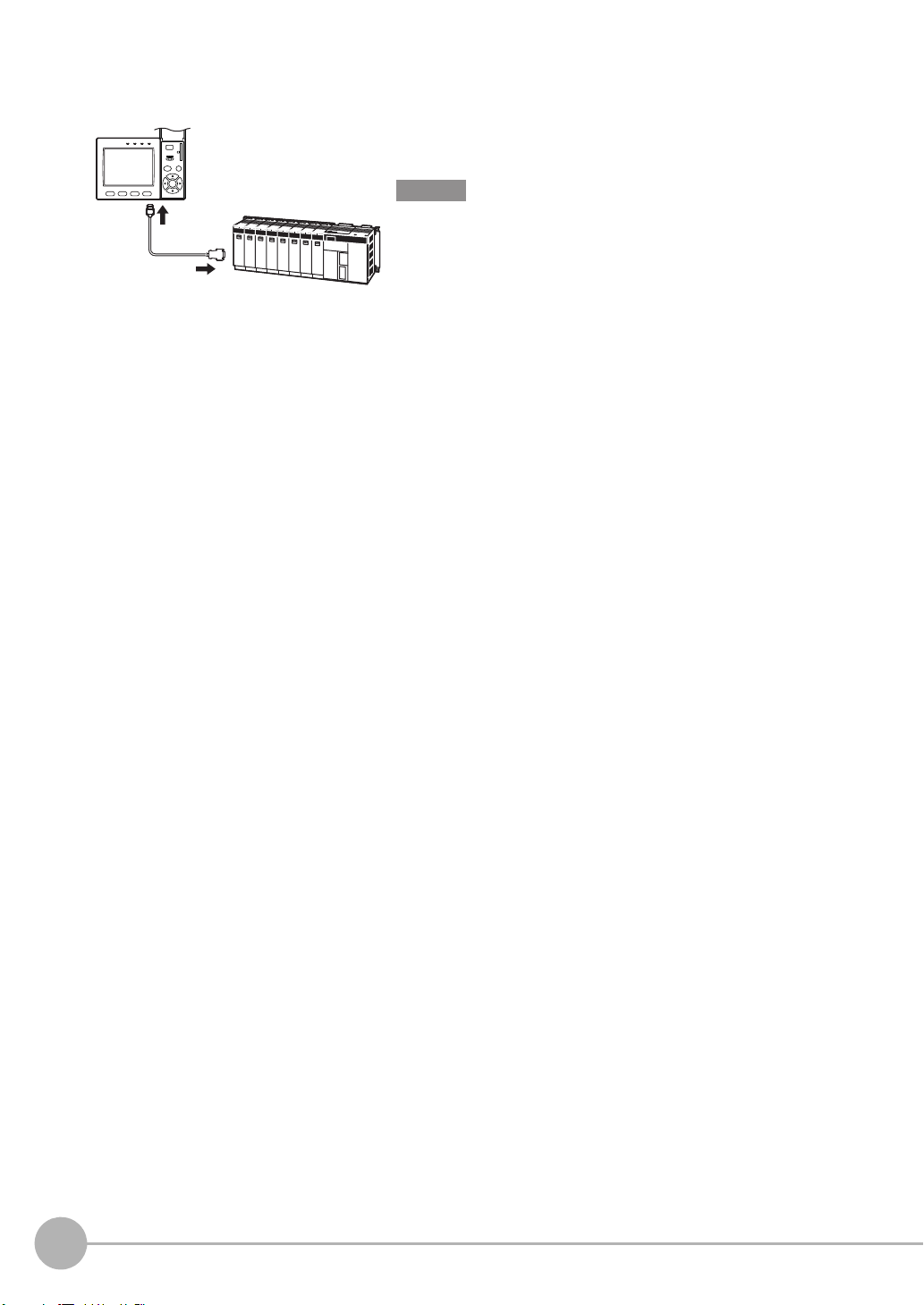
Connecting a PLC
Use the exclusive RS-232C cable (ZFX-XPT2A) / RS-422 cable
(ZFX-XPT2B) to connect the Controller to a PLC.
Important
When connecting to a PLC, refer to the Instruction Manual for the
PLC.
6
Connection
ZFX-C Serial Communication Command Reference
Page 9
About Communication Commands
Command data Delimiter
Response data
Record
separator
Record
separator
Record
separator
KO
RE
When processing ends successfully
When processing fails
Command/Response Format
< Command >
< Response >
Command data Specifies the command and parameters in ASCII code.
Response data Stores the acquired data.
Delimiter This control code indicates the end of the data.
Record separator This delimiter is appended to one session's worth of output data. (default delimiter: CR)
ZFX-C Serial Communication Command Reference
About Communication Commands
7
Page 10
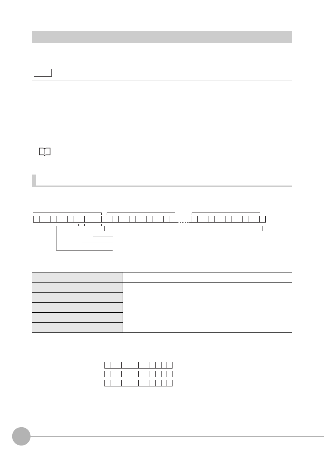
Configuration of Measurement Value Data
Note
Field separator
Number of digits past the decimal point: max. 3
Decimal separator: 1 digit
Sign + number of digits of integer section: max. 8 digits
(Insert "0" for spaces.)
Record
separator
Measurement value of data 0 Measurement value of data 1 Measurement value of data 31
23456 . 789
C
R
01
04567 . 800
C
R
00
04567 . 800
C
R
-0
123456.789
4567.8
-4567.8
< Measurement value > < Data structure >
Example: Number of digits of integer section: 7, number of digits past the decimal point: 3,
decimal separator: period
The following explains the output format of measurement values.
To output measurement values by serial communication, the following items must be set.
Output content
Set the output content as an expression.
Set the output content at [Setup] - [Support] - [Calculation] - [Data].
Output destination
Specify [RS-232C/422] or [USB] at [System] - [Output] - [Data output].
Output format
Set the output format at [System] - [Output] - [Serial output].
For detailed settings, refer to the User's Manual.
ASCII Format
Up to 32 results are output as a data structure of fixed length of up to 12 characters including the sign.
Sign The sign of the measurement value is stored. Plus: 0/Minus: -
Number of digits of integer section "0" is inserted in spaces in the integer section and digits past the decimal
Number of digits past the decimal point
Decimal separator
Field separator
Record separator
8
About Communication Commands
point.
When a value is greater than the preset number of digits, all digits other
than the sign digit become "9".
Output range: -9999999.999 to 09999999.999
ZFX-C Serial Communication Command Reference
Page 11
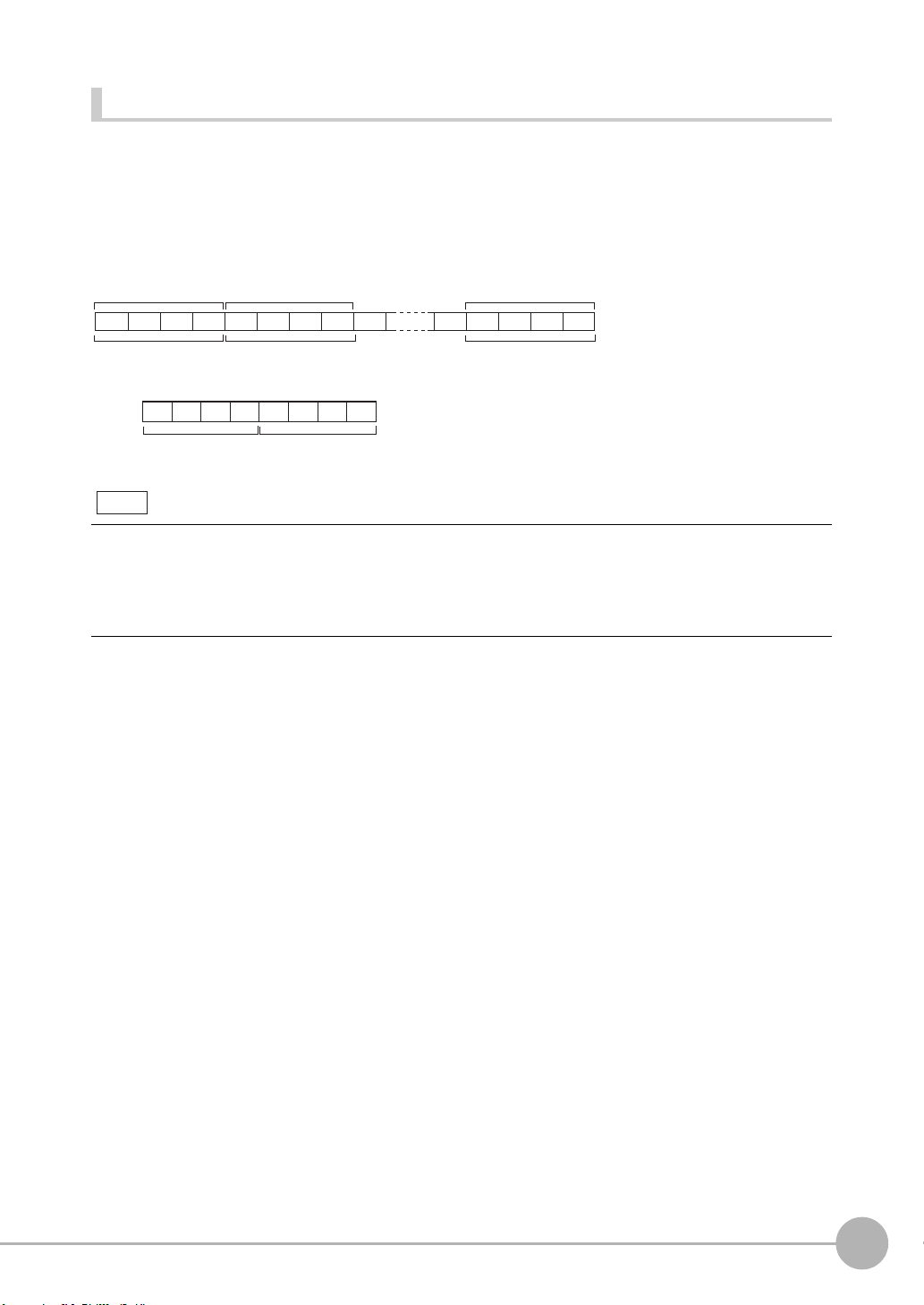
Binary Format
4 bytes
Measurement value
of data 0 x 1000
Measurement value
of data 1 x 1000
Measurement value
of data 31 x 1000
4 bytes 4 bytes
Example: Data 0 "256.324" and data 1 "-1.000"
Data 0: 256324
(256.324 x 1000)
Data 1: -1000
(-1.000 x 1000)
Note
The value obtained by multiplying the measurement value by 1000 is output continuously as four bytes per
single data item. Minus values are output as 2's complement. Up to 32 results can be output.
The binary format differs from the ASCII format in that data separators, such as field separator or record
separator, do not exist.
Output range: -2147483.648 to 2147483.647
$00 $44$03 $FF$E9 $FF $FC $18
• A value obtained by multiplying by 1000 also is output as the judgment result (JG).
OK: 0
NG: -1000 (-1 x 1000)
• When the measurement value is less than -2147483.648, "-2147483.648" is output.
When the measurement value is greater than 2147483.647, "2147483.647" is output.
ZFX-C Serial Communication Command Reference
About Communication Commands
9
Page 12

Available Commands
Bank Control Commands
Command name Description Page
BANK (or BK) This command acquires the current bank No. p.12
This command switches the bank to be used. p.12
BANKGROUP (or BG) This command acquires the current bank group No. p.13
This command switches the bank group to be used. p.13
Measurement Control/Measurement Value Acquisition Commands
Command name Description Page
MEASDATA (or MD) This command acquires the measurement result of the measurement item. p.14
MEASURE (or M) This command executes a single measurement. p.15
This command starts continuous measurement. p.16
This command ends continuous measurement. p.16
This command performs re-measurement using saved images. p.16
Setting Acquisition/Change Commands
Command name Description Page
DATE (or DT) This command acquires the date and time of the calendar timer incorporated
into the Controller.
This command changes the date and time of the calendar timer incorporated
into the Controller.
MODELSET (or MS) This command re-registers the model of the specified item. It does not reset
filters, etc.
MEASPARA (or MP) This command acquires the detailed conditions and thresholds of specified
measurement items.
This command sets the detailed conditions and thresholds of specified
measurement items.
POSIPARA (or PP) This command acquires the detailed conditions and the threshold value of
position shift correction.
This command sets the detailed conditions and the threshold value of position
shift correction.
PASSWORD (or PW) This command acquires the currently set password. p.23
It sets and changes the password character string. p.23
VERGET (or VR) This command acquires the version information of the Controller. p.24
p.17
p.17
p.18
p.19
p.19
p.21
p.21
Backup/Restore Commands
Command name Description Page
BGRLOAD (or GL)
BGRSAVE (or GS)
BNKLOAD (or BL) This command uploads bank data to the Controller from an external device. p.27
10
About Communication Commands
This command uploads bank group data to the Controller from an external device.
This command uploads bank group data to the Controller from an SD card. p.25
This command backs up bank group data to an external device from the Controller.
This command backs up bank group data to an SD card from the Controller. p.26
This command uploads bank data to the Controller from an SD card. p.27
ZFX-C Serial Communication Command Reference
p.25
p.26
Page 13

Command name Description Page
BNKSAVE (or BS) This command backs up bank data to an external device from the Controller. p.28
This command backs up bank data to an SD card from the Controller. p.28
DATASAVE (or SV) This command saves the current settings to the Controller. p.29
IMGLOAD (or IL) This command uploads image data to the Controller from an external device. p.29
This command uploads image data to the Controller from an SD card. p.30
IMGSAVE (or IS) This command backs up image data to an external device from the Controller. p.31
This command backs up image data to an SD card from the Controller. p.32
SYSLOAD (or SL) This command uploads system data to the Controller from an external device. p.33
This command uploads system data to the Controller from an SD card. p.33
SYSSAVE (or SS) This command backs up system data to an external device from the Controller. p.34
This command backs up system data to an SD card from the Controller. p.34
Utility Commands
Command name Description Page
CLRMEAS (or CM) Clears measurement results. p.35
CLRERR (or CE) Clears error output results. p.35
ERRHISTORY (or EH) Outputs a history of up to five of the latest errors. p.36
CAPTURE(CP) Executes display capture, and outputs this to the host or SD card as an image. p.37
RESET (or RS) This command restarts the Controller. p.38
EXIT This command ends the TELNET connection for Ethernet communications and
disconnects the line.
p.38
ZFX-C Serial Communication Command Reference
About Communication Commands
11
Page 14
Bank Control Commands
BANK
C
R
BK
C
R
or
C
R
ER
C
R
OK
C
R
When processing ends successfully
When processing fails
Bank No. (max. 2 digits)
BANK
C
R
BK
C
R
Bank No.
(max. 2 digits)
or
Bank No.
(max. 2 digits)
OK
C
R
ER
C
R
When processing ends successfully
When processing fails
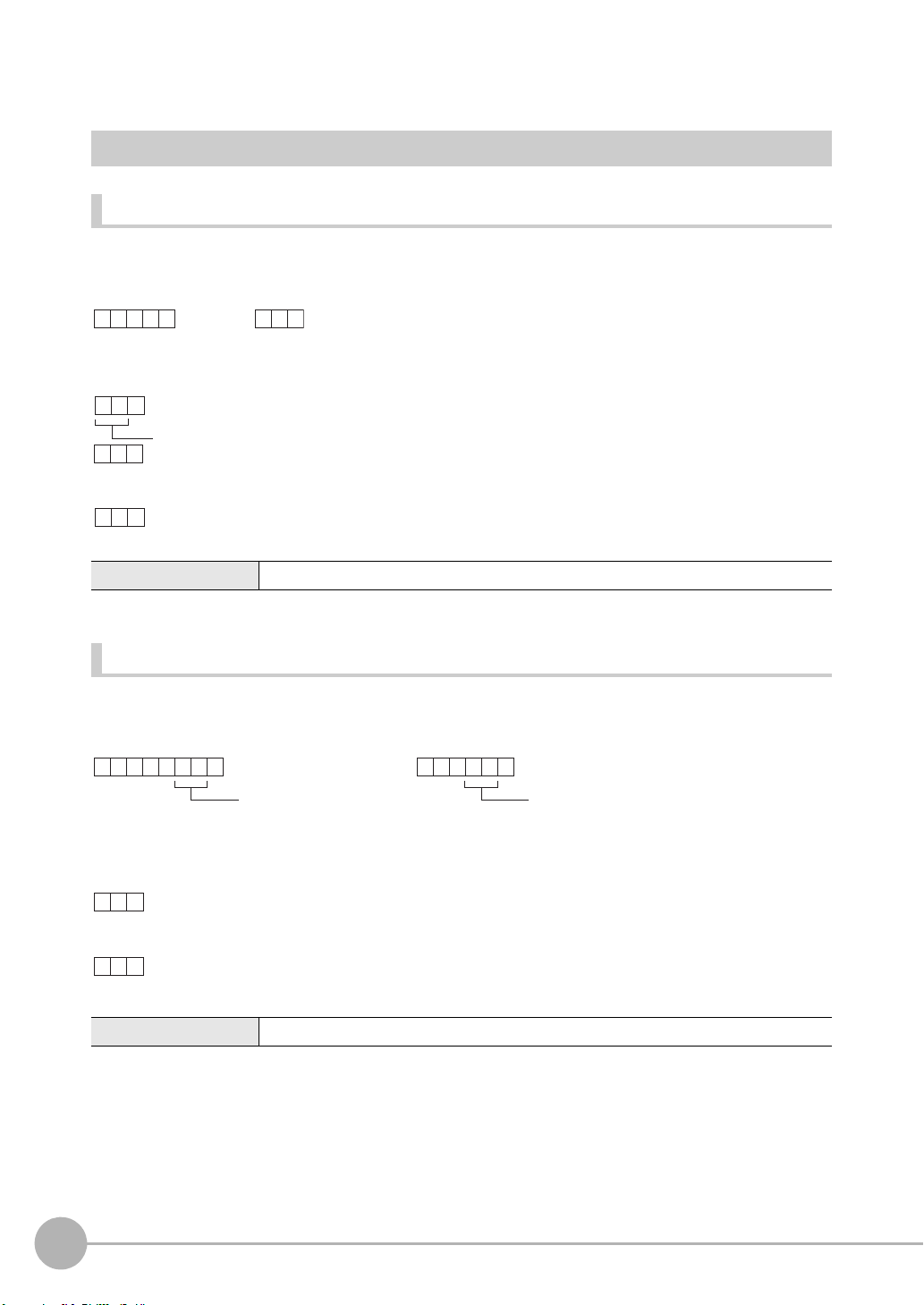
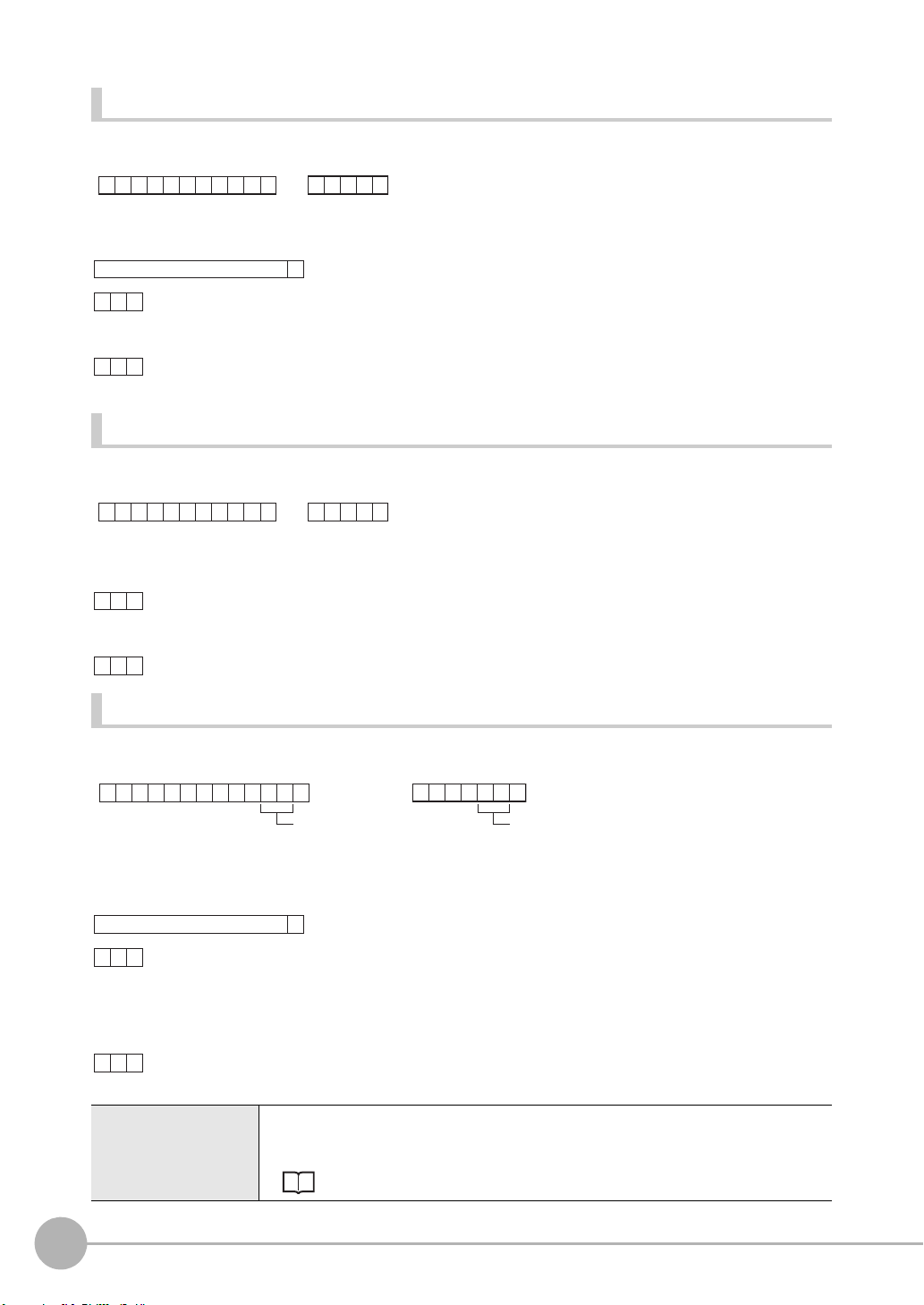
Acquiring/Switching the Bank No. < BANK command >
Acquiring a bank No.
This command acquires the current bank No.
< Command format >
< Response format >
< Explanation of parameters >
Bank No. The acquired bank No. is returned. (0 to 31)
Switching to another bank
This command switches the bank to be used.
< Command format >
< Response format >
< Explanation of parameters >
Bank No. Specifies the bank No. after the bank is switched. (0 to 31)
12
About Communication Commands
ZFX-C Serial Communication Command Reference
Page 15
Acquiring/Switching the Bank Group No. < BANKGROUP command >
BA
C
R
B G
C
R
NKGROUP
or
C
R
ER
C
R
OK
C
R
When processing ends successfully
When processing fails
Bank group No. (max. 2 digits)
BA
C
R
B G
C
R
NKGROUP
Bank group No.
(max. 2 digits)
or
Bank group No.
(max. 2 digits)
OK
C
R
ER
C
R
When processing ends successfully
When processing fails
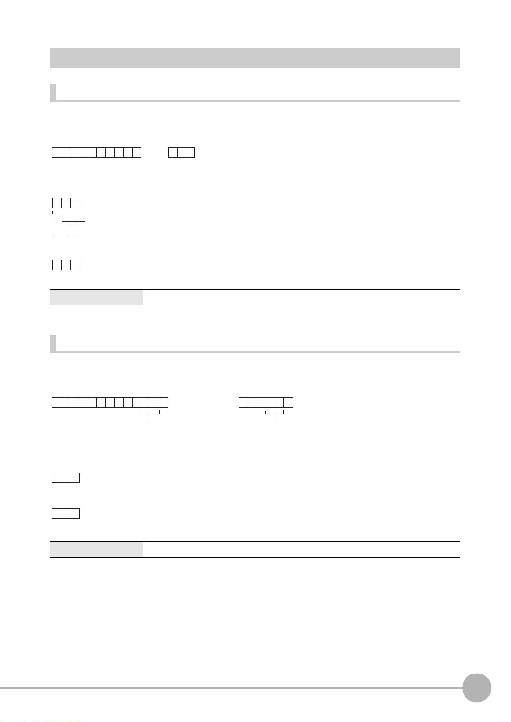
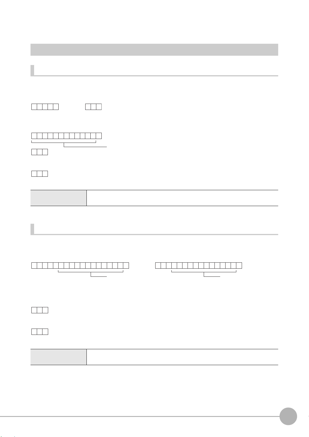
Acquiring a bank group No.
This command acquires the current bank group No.
< Command format >
< Response format >
< Explanation of parameters >
Bank group No. The acquired bank group No. is returned. (0 to 31)
Switching bank group Nos.
This command switches the bank group to be used.
< Command format >
< Response format >
< Explanation of parameters >
Bank group No. Specifies the bank group No. after the bank group is switched. (0 to 31)
ZFX-C Serial Communication Command Reference
About Communication Commands
13
Page 16
Measurement Control/Measurement Value Acquisition
MEA S
C
R
MD
C
R
D A T A
or
Data No.
(max. 3 digits)
Data No.
(max. 3 digits)
Measurement
item No.
(max. 3 digits)
Measurement
item No.
(max. 3 digits)
O K
C
R
E R
C
R
C
R
When processing ends successfully
When processing fails
Measurement value
Commands
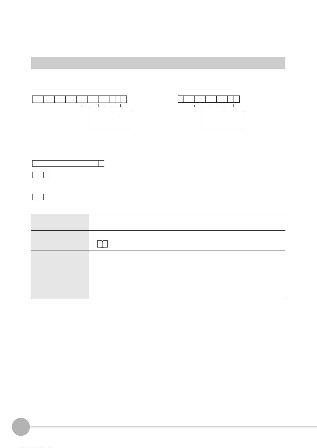
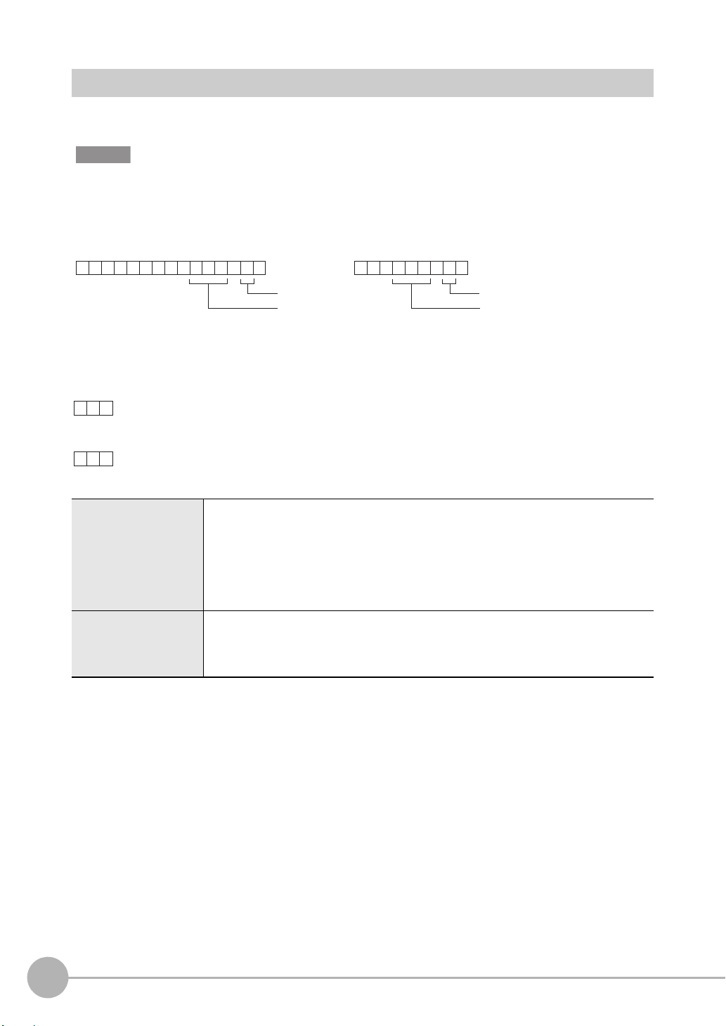
Acquiring the Measurement Result of the Measurement Item < MEASDATA command >
This command acquires the measurement result of the measurement item.
< Command format >
< Response format >
< Explanation of parameters >
Measurement item No. Specifies the measurement item No. (0 to 127 (ZFX-C20/C25/C10H/C15H), 0 to 31 (ZFX-
C10/C15))
Data No. Specifies the data No. (0 to 127)
For details, see "Parameter List (p.39)."
Measurement value The acquired measurement value is returned in ASCII code.
The measurement value is not dependent on the format (ASCII/binary) specified in the
output conditions.
• Minus sign: -, plus sign: none
• The size of the integer section is variable.
• The decimal point is indicated by a period ".".
• The maximum number of digits past the decimal point is three.
14
About Communication Commands
ZFX-C Serial Communication Command Reference
Page 17
Executing Measurement < MEASURE command >
M EAS
C
R
M
C
R
URE
or
O K
C
R
E R
C
R
C
R
When processing ends successfully
When processing fails
Measurement value
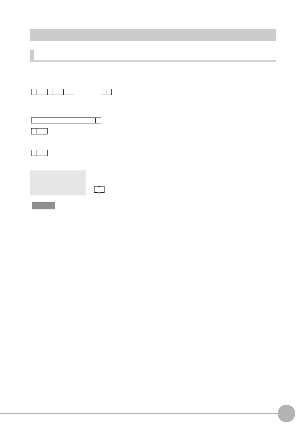
Executing a Single Measurement
This command executes a single measurement.
< Command format >
< Response format >
< Explanation of parameters >
Measurement value The acquired measurement value is returned. The measurement value is output in the
format (ASCII/binary) specified in the output conditions.
Configuration of Measurement Value Data p.8
Important
Measurement values are output only when an expression is set at [Setup] - [Support] - [Calculation] - [Data], and [RS232C/422] or [USB] is specified at [System] - [Output] - [Data output].
ZFX-C Serial Communication Command Reference
About Communication Commands
15
Page 18
Starting Continuous Measurement
MEA S
C
R
M/C
C
R
URE / C
or
O K
C
R
E R
C
R
C
R
When processing ends successfully
When processing fails
Measurement value
(for number of continuous measurements)
MEA S
C
R
M/E
C
R
URE / E
or
OK
C
R
ER
C
R
When processing ends successfully
When processing fails
M EAS
C
R
M /
C
R
URE/I I
or
Save memory No.
(max. 2 digits)
Save memory No.
(max. 2 digits)
O K
C
R
E R
C
R
C
R
When processing ends successfully
When processing fails
• Measurement images are not stored in the specified save memory No.
• [Image storage] option is set to OFF
Measurement value
< Command format >
< Response format >
Ending Continuous Measurement
< Command format >
< Response format >
Performing re-measurement using saved images
< Command format >
< Response format >
< Explanation of parameters >
Measurement value The re-measurement value for the saved image of specified save memory No. is returned.
When the save memory No. is omitted, the re-measurement value for the latest saved
16
About Communication Commands
image is returned.
Configuration of Measurement Value Data p.8
ZFX-C Serial Communication Command Reference
Page 19
Setting Acquisition/Change Commands
D ATE
C
R
D T
C
R
or
C
R
O K
C
R
E R
C
R
When processing ends successfully
When processing fails
Year/hour/day/hour/minute/second
D ATE
C
R
D T
C
R
Year/hour/day/hour/
minute/second
or
Year/hour/day/hour/
minute/second
OK
C
R
ER
C
R
When processing ends successfully
When processing fails
Acquiring/Changing the Date Setting < DATE command >
Acquiring the date setting
This command acquires the date and time of the calendar timer incorporated into the Controller.
< Command format >
< Response format >
< Explanation of parameters >
Year/hour/day/hour/
minute/second
The acquired date and time are returned as numerical values of two digits each.
Example: 060301120020 → 12:00:20 on March 1st, 2006
.
Changing the Date Setting
This command changes the date and time of the calendar timer incorporated into the Controller.
< Command format >
< Response format >
< Explanation of parameters >
Year/hour/day/hour/
minute/second
ZFX-C Serial Communication Command Reference
Specifies the date and time.
Example: 060301120020 → 12:00:20 on March 1st, 2006
About Communication Commands
17
Page 20
Re-registering the Model of the Specified Item < MODELSET command >
MOD E
C
R
MS
C
R
LSET
or
Attribute
Measurement
item No.
(max. 3 digits)
Attribute
Measurement
item No.
(max. 3 digits)
OK
C
R
ER
C
R
When processing ends successfully
When processing fails
This command re-registers the model of the specified item. It does not reset filters, etc.
Important
The execution of this command does not re-register any model for the flexible search, graphic search and grouping
items.
< Command format >
< Response format >
< Explanation of parameters >
Measurement item No. Specifies the measurement item No.
Measurement items: 0 to 127 (ZFX-C20/C25/C10H/C15H), 0 to 31 (ZFX-C10/C15)
Position correction items: 0 to 3
0: Position correction 0 of camera 0
1: Position correction 1 of camera 0
2: Position correction 0 of camera 1
3: Position correction 1 of camera 1
Attribute Specifies measurement item or position correction item.
0: Measurement item
1: Position correction item
Default is measurement item.
18
About Communication Commands
ZFX-C Serial Communication Command Reference
Page 21

Setting/Acquiring the Measurement Conditions < MEASPARA command >
M EAS
C
R
Setting valueC
R
Setting value
MPP A R A
or
Data No.
(max. 3 digits)
Measurement
item No.
(max. 3 digits)
Data No.
(max. 3 digits)
Measurement
item No.
(max. 3 digits)
OK
C
R
ER
C
R
When processing ends successfully
When processing fails
C
R
C
R
M EASPA R A MP
or
Data No.
(max. 3 digits)
Measurement
item No.
(max. 3 digits)
Data No.
(max. 3 digits)
Measurement
item No.
(max. 3 digits)
C
R
Acquired value
O K
C
R
E R
C
R
When processing ends successfully
When processing fails
Setting measurement conditions
This command sets the detailed conditions and thresholds of specified items.
< Command format >
< Response format >
< Explanation of parameters >
Measurement item No. Specifies the measurement item No. (0 to 127)
Data No. Specifies the data No. (0 to 127)
For details, see
Setting value Specifies the setting value.
For details, see
"Parameter List (p.39)."
"Parameter List (p.39)."
Acquiring measurement conditions
This command acquires the detailed conditions and thresholds of specified items.
< Command format >
< Response format >
ZFX-C Serial Communication Command Reference
About Communication Commands
19
Page 22

< Explanation of parameters >
Measurement item No. Specifies the measurement item No. (0 to 127)
Data No. Specifies the data No. (0 to 127)
For details, see
Acquired value The detailed conditions and thresholds of specified items is returned.
For details, see
"Parameter List (p.39)."
"Parameter List (p.39)."
20
About Communication Commands
ZFX-C Serial Communication Command Reference
Page 23

Setting/Acquiring Position Shift Correction Condition< POSIPARA Command >
POS I
C
R
Setting valueC
R
Setting value
PPP A R A
or
Data No.
(max. 3 digits)
Position correction
item No.
(max. 1 digits)
Data No.
(max. 3 digits)
Position correction
item No.
(max. 1 digits)
OK
C
R
ER
C
R
When processing ends successfully
When processing fails
C
R
C
R
P A R APOS I P P
or
Data No.
(max. 3 digits)
Position correction
item No.
(max. 1 digits)
Data No.
(max. 3 digits)
Position correction
item No.
(max. 1 digits)
Setting position shift correction conditions
This command sets the detailed conditions and thresholds of position shift correction.
< Command format >
< Response format >
< Explanation of parameters >
Position correction item
No.
Data No. Specifies the data No. (0 to 127)
Setting value Specifies the setting value.
Specifies the position correction item No. (0 to 3)
Item Nos are assigned as follows:
0: Position correction0 of camera0
1: Position correction1 of camera0
2: Position correction0 of camera1
3: Position correction1 of camera1
For details, see
For details, see
"Parameter List (p.39)."
"Parameter List (p.39)."
Acquiring position shift correction conditions
This command acquires the detailed conditions and thresholds of position shift correction.
< Command format >
ZFX-C Serial Communication Command Reference
About Communication Commands
21
Page 24

< Response format >
C
R
Acquired value
O K
C
R
E R
C
R
When processing ends successfully
When processing fails
< Explanation of parameters >
Position correction item
No.
Data No. Specifies the data No. (0 to 127)
Acquired value The detailed conditions and thresholds of position correction is returned.
Specifies the position correction item No. (0 to 3)
Item Nos are assigned as follows:
0: Position correction0 of Camera0
1: Position correction1 of Camera0
2: Position correction0 of Camera1
3: Position correction1 of Camera1
For details, see
For details, see
"Parameter List (p.39)."
"Parameter List (p.39)."
22
About Communication Commands
ZFX-C Serial Communication Command Reference
Page 25

Acquiring/Changing Passwords < PASSWORD command >
P A SS
C
R
P W
C
R
W ORD
or
C
R
ER
C
R
OK
C
R
When processing ends successfully
When processing fails
Password
P A SS
C
R
P W
C
R
W ORD
Password
or
Password
OK
C
R
ER
C
R
When processing ends successfully
When processing fails
Acquiring the password
This command acquires the currently set password.
< Command format >
< Response format >
< Explanation of parameters >
Password A password of any eight alphanumeric characters is returned.
Setting/Changing the password
This command sets and changes the password character string.
< Command format >
< Response format >
< Explanation of parameters >
Password Specifies a password of any eight alphanumeric characters.
ZFX-C Serial Communication Command Reference
About Communication Commands
23
Page 26

Acquiring the Version No. < VERGET command >
VERG
C
R
V R
C
R
ET
or
ZFX- V erX.XX
C
R
ER
C
R
OK
C
R
Version No.
Model information
When processing ends successfully
When processing fails
This command acquires the version information of the Controller.
< Command format >
< Response format >
< Explanation of parameters >
Model information The model No. of the Controller is returned.
Version No. The version No. of the Controller's firmware is returned.
24
About Communication Commands
ZFX-C Serial Communication Command Reference
Page 27

Backup/Restore Commands
B GR L
C
R
G L
C
R
O A D 00
Bank group No.
(max. 2 digits)
or
Bank group No.
(max. 2 digits)
OK
C
R
ER
C
R
R EAD
C
R
Y
When processing ends successfully
When processing fails
B GRL
C
R
GL
C
R
O A D11
or
File name File name
Bank group No.
(max. 2 digits)
Bank group No.
(max. 2 digits)
OK
C
R
ER
C
R
When processing ends successfully
When processing fails
Uploading Bank Group Data < BGRLOAD command >
Uploading bank group data to the Controller from an external device
This command uploads the bank group data to the Controller by XMODEM protocol. The bank group data is
loaded to the specified bank group No.
< Command format >
< File transfer >
The bank group data is transferred by XMODEM (-CRC or SUM) after READY is received. XMODEM (-1K) is
not supported.
< Response format >
< Explanation of parameters >
Bank group No. Specifies the bank group No. to upload. (0 to 31)
Uploading bank group data to the Controller from an SD card
This command uploads bank group data to the Controller from an SD card.
< Command format >
< Response format >
< Explanation of parameters >
Bank group No. Specifies the bank group No. to upload. (0 to 31)
File name
ZFX-C Serial Communication Command Reference
Specifies the file name within eight alphanumeric characters. (An extension is not required.)
About Communication Commands
25
Page 28

Backing up Bank Group Data < BGRSAVE command >
B GR S
C
R
GS
C
R
AVE 0 0
Bank group No.
(max. 2 digits)
or
Bank group No.
(max. 2 digits)
OK
C
R
ER
C
R
R EAD
C
R
Y
When processing ends successfully
When processing fails
B GRS
C
R
GS
C
R
AVE11
or
File name File name
Bank group No.
(max. 2 digits)
Bank group No.
(max. 2 digits)
OK
C
R
ER
C
R
When processing ends successfully
When processing fails
Backing up bank group data to an external device from the Controller
This command backs up the bank group data from the Controller by XMODEM protocol.
< Command format >
< File transfer >
The bank group data is transferred by XMODEM (-CRC or SUM) after READY is received. XMODEM (-1K) is
not supported.
< Response format >
< Explanation of parameters >
Bank group No. Specifies the bank group No. to back up. (0 to 31)
Backing up bank group data to an SD from the Controller
This command backs up bank group data to an SD card from the Controller.
< Command format >
< Response format >
< Explanation of parameters >
Bank group No. Specifies the bank group No. to back up. (0 to 31)
File name The file can be given any name within eight alphanumeric characters. (An extension is not
required.)
26
About Communication Commands
ZFX-C Serial Communication Command Reference
Page 29

Uploading Bank Data < BNKLOAD command >
BNKL
C
R
BL
C
R
O A D 00
Bank No.
(max. 2 digits)
or
Bank No.
(max. 2 digits)
OK
C
R
ER
C
R
R EAD
C
R
Y
When processing ends successfully
When processing fails
B NKL
C
R
B L
C
R
O A D11
or
File name File name
Bank No.
(max. 2 digits)
Bank No.
(max. 2 digits)
OK
C
R
ER
C
R
When processing ends successfully
When processing fails
Uploading bank data to the Controller from an external device
This command uploads the bank data to the Controller by XMODEM protocol.
< Command format >
< File transfer >
The bank data is transferred by XMODEM (-CRC or SUM) after READY is received. XMODEM (-1K) is not
supported.
< Response format >
< Explanation of parameters >
Bank No. Specifies the bank No. to upload. (0 to 31)
Uploading bank data to the Controller from an SD card
This command uploads bank data to the Controller from an SD card.
< Command format >
< Response format >
< Explanation of parameters >
Bank No. Specifies the bank No. to upload. (0 to 31)
File name Specifies the file name within eight alphanumeric characters. (An extension is not
required.)
ZFX-C Serial Communication Command Reference
About Communication Commands
27
Page 30

Backing up Bank Data < BNKSAVE command >
BNKS
C
R
B S
C
R
AVE 0 0
Bank No.
(max. 2 digits)
or
Bank No.
(max. 2 digits)
OK
C
R
ER
C
R
R EAD
C
R
Y
When processing ends successfully
When processing fails
B NKS
C
R
B S
C
R
AVE11
or
File name File name
Bank No.
(max. 2 digits)
Bank No.
(max. 2 digits)
OK
C
R
ER
C
R
When processing ends successfully
When processing fails
Backing up bank data to an external device from the Controller
This command backs up the bank data from the Controller by XMODEM protocol.
< Command format >
< File transfer >
The bank data is transferred by XMODEM (-CRC or SUM) after READY is received. XMODEM (-1K) is not
supported.
< Response format >
< Explanation of parameters >
Bank No. Specifies the bank No. to back up. (0 to 31)
Backing up bank data to an SD card from the Controller
This command backs up bank data to an SD card from the Controller.
< Command format >
< Response format >
< Explanation of parameters >
Bank No. Specifies the bank No. to back up. (0 to 31)
File name The file can be given any name within eight alphanumeric characters. (An extension is not
required.)
28
About Communication Commands
ZFX-C Serial Communication Command Reference
Page 31

Saving the Current Settings to the Controller < DATASAVE command >
D ATA
C
R
S V
C
R
S AVE
or
OK
C
R
ER
C
R
When processing ends successfully
When processing fails
IMGL
C
R
IL
C
R
O A D 00
or
Save
memory No.
(max. 2 digits)
Save
memory No.
(max. 2 digits)
OK
C
R
ER
C
R
R EAD
C
R
Y
When processing ends successfully
When processing fails
This command saves the current settings to the Controller.
No parameters are provided for this command.
< Command format >
< Response format >
Uploading Image Data < IMGLOAD command >
Uploading image data to the Controller from an external device
This command uploads image data to the Controller by XMODEM protocol.
< Command format >
< File transfer >
The image data is transferred by XMODEM (-CRC or SUM) after READY is received. XMODEM (-1K) is not
supported.
< Response format >
< Explanation of parameters >
Save memory No. Specifies the No. of the save memory for saving the image data to. (0 to 99)
ZFX-C Serial Communication Command Reference
About Communication Commands
29
Page 32

Uploading image data to the Controller from an SD card
IMGL
C
R
IL
C
R
O A D11
or
File name File name
Save
memory No.
(max. 2 digits)
Save
memory No.
(max. 2 digits)
OK
C
R
ER
C
R
When processing ends successfully
When processing fails
This command uploads image data to the Controller from an SD card.
< Command format >
< Response format >
< Explanation of parameters >
Save memory No. Specifies the No. of the save memory for saving the image data to. (0 to 99)
File name Specifies the file name (within 8 characters, excluding the file extension). File extensions
".GRY" (image captured by a monochrome camera) or ".BYR" (image captured by a color
camera) are allowed.
30
About Communication Commands
ZFX-C Serial Communication Command Reference
Page 33

Backing up Image Data < IMGSAVE command >
IMGS
C
R
IS
C
R
AVE 00
or
Save
memory No.
(max. 2 digits)
Save
memory No.
(max. 2 digits)
OK
C
R
ER
C
R
R EAD
C
R
Y
When processing ends successfully
When processing fails
Backing up image data from the Controller to an external device
This command backs up image data from the Controller by XMODEM protocol.
< Command format >
< File transfer >
The image data is transferred by XMODEM (-CRC or SUM) after READY is received. XMODEM (-1K) is not
supported.
< Response format >
< Explanation of parameters >
Save memory No. Specifies the No. of the save memory for backing up the image data to. (0 to 99)
When "-1" is specified for the Save memory No., the latest image data of camera 0 is
specified.
When "-2" is specified for the Save memory No., the latest image data of camera 1 is
specified.
ZFX-C Serial Communication Command Reference
About Communication Commands
31
Page 34

Backing up image data from the Controller to an SD card
IMGS
C
R
IS
C
R
AVE11
or
File name File name
Save
memory No.
(max. 2 digits)
Save
memory No.
(max. 2 digits)
OK
C
R
ER
C
R
ER 0
C
R
ER 1
C
R
When processing ends successfully
When processing fails
When an SD card is not inserted
When there is no free space on the SD card
This command backs up image data from the Controller to an SD card.
< Command format >
< Response format >
< Explanation of parameters >
Save memory No. Specifies the No. of the save memory for backing up the image data to. (0 to 99)
When "-1" is specified for the Save memory No., the latest image data is specified.
File name Files can be given any file name up to 5 characters long. (Entry of a file extension is not
necessary.)
When performing measurement on two cameras, the image data of both cameras is
saved. In this case, the file names are automatically appended with "C0" and "C1".
Image data from camera 0: file name_C0.BYR or file name_C1.GRY
Image data from camera 1: file name_C1.BYR or file name_C1.GRY
32
About Communication Commands
ZFX-C Serial Communication Command Reference
Page 35

Uploading System Data < SYSLOAD command >
S Y S L
C
R
S L
C
R
O A D 00
or
OK
C
R
ER
C
R
R EAD
C
R
Y
When processing ends successfully
When processing fails
S Y S L
C
R
S L
C
R
O A D11
File name
or
File name
OK
C
R
ER
C
R
When processing ends successfully
When processing fails
Uploading system data to the Controller from an external device
This command uploads the system data to the Controller by XMODEM protocol.
No parameters are provided for this command.
< Command format >
< File transfer >
The system data is transferred by XMODEM (-CRC or SUM) after READY is received. XMODEM (-1K) is not
supported.
< Response format >
Uploading system data to the Controller from an SD card
This command uploads system data to the Controller from an SD card.
< Command format >
< Response format >
< Explanation of parameters >
File name Specifies the file name within eight alphanumeric characters. (An extension is not
required.)
ZFX-C Serial Communication Command Reference
About Communication Commands
33
Page 36

Backing up System Data < SYSSAVE command >
S Y SS
C
R
SS
C
R
AVE 0 0
or
OK
C
R
ER
C
R
R EAD
C
R
Y
When processing ends successfully
When processing fails
SYSS
C
R
SS
C
R
AVE11
File name
or
File name
OK
C
R
ER
C
R
When processing ends successfully
When processing fails
Backing up system data to an external device from the Controller
This command backs up the system data from the Controller by XMODEM protocol.
No parameters are provided for this command.
< Command format >
< File transfer >
The system data is transferred by XMODEM (-CRC or SUM) after READY is received. XMODEM (-1K) is not
supported.
< Response format >
Backing up system data to an SD card from the Controller
This command backs up system data to an SD card from the Controller.
< Command format >
< Response format >
< Explanation of parameters >
File name The file can be given any name within eight alphanumeric characters. (An extension is not
required.)
34
About Communication Commands
ZFX-C Serial Communication Command Reference
Page 37

Utility Commands
C L RCM
C
R
M E
C
R
A S
or
OK
C
R
ER
C
R
When processing ends successfully
When processing fails
C L RCE
C
R
E RR
C
R
or
OK
C
R
ER
C
R
When processing ends successfully
When processing fails
Clearing Measurement Values < CLRMEAS Command >
This command clears the following measurement results.
• Judgment results and measurement values of measurement items
• Judgment results and measurement values of expressions
• Logging data
• Parallel external output signals (OR, DO0 to DO15)
No parameters are provided for this command.
< Command format >
< Response format >
Clearing Error Output < CLRERR Command >
Clears the error output results.
The parallel external output signal (ERROR) is turned OFF to turn the ERROR LED OFF.
No parameters are provided for this command.
< Command format >
< Response format >
ZFX-C Serial Communication Command Reference
About Communication Commands
35
Page 38

Outputting the Error History < ERRHISTORY Command >
E RR EH
C
R
HIS T O
C
R
R Y
or
ER
C
R
When processing ends successfully
When processing fails
,,,,
C
R
Error Code No.
(0 to 9)
When no error occurs
,,,,-1 -1 -1 -1 -1
C
R
,,,,33-1 -1 -1
C
R
Example: When handshaking timeout error occurs two times
This command outputs a history of up to five of the latest errors.
This command shows information of up to five of the latest errors by error code No. (0 to 9).
"-1" is returned other than error code No. if the number of error occurrences does not exceed five.
< Command format >
< Response format >
< Explanation of parameters >
Error Code No. Description
0 Trigger input error
1 Parallel command error
2 SD CARD access error
3 Parallel timeout error
4 USB connection error
5 LAN connection error
6 Image input error
8 VDIN timeout error
9 Camera communication error
36
About Communication Commands
ZFX-C Serial Communication Command Reference
Page 39

Executing Display Capture to Output an Image < CAPTURE Command >
Note
C A PCP
C
R
T U
C
R
R E
or
Mode No.
(0 or 1)
Mode No.
(0 or 1)
When processing ends successfully
When processing fails
When Mode No. is set to 0:
When processing ends successfully
When processing fails
When Mode No. is set to 1 or omitted:
This command executes display capture.
Captured images are output to the SD card or external devices.
Important
When parameter (mode No.) input is omitted, captured images are output to the SD card.
Captured images are transferred to external devices by XMODEM protocol.
Images are sent in bitmap format. Save the images with ".BMP" file extensions.
< Command format >
< File transfer >
When the mode No. is set to 0 and the image is output to external devices, the image data is transferred by
XMODEM (-CRC or SUM) after READY is received. XMODEM (-1k) is not supported.
< Response format >
R EAD
OK
ER
OK
ER
C
Y
R
C
R
C
R
C
R
C
R
< Explanation of parameters >
Mode No. Description
0 Display capture is executed and the captured display is output as an image to external
1 or omitted Display capture is executed and the captured display is output as an image to SD card.
devices.
The captured image is stored to CAPTURE directory in the SD card.
ZFX-C Serial Communication Command Reference
About Communication Commands
37
Page 40

Restarting the Controller < RESET command >
R E S
C
R
RS
C
R
ET
or
ER
C
R
When processing ends successfully
When processing fails
None
EX
C
R
IT
ER
C
R
When processing ends successfully
When processing fails
None
This command restarts the Controller. No parameters are provided for this command.
< Command format >
< Response format >
Ending Ethernet Communications < EXIT command >
This command ends the TELNET connection for Ethernet communications and disconnects the line.
No parameters are provided for this command.
< Command format >
< Response format >
38
About Communication Commands
ZFX-C Serial Communication Command Reference
Page 41

Parameter List
MEASDATA Command
Shape inspection parameters
Pattern search
Data No. Parameter Output Range
0 Judgment result 0: OK
-1: NG
-2: not measured
1 Correlation 0 to 100
2 Measurement position X -9999.999 to 9999.999
3 Measurement position Y -9999.999 to 9999.999
4 Measurement angle -180 to 180
5 Search number 0 to 99
6 Reference position X -9999.999 to 9999.999
7 Reference position Y -9999.999 to 9999.999
8 Reference angle -180 to 180
9 Position difference X -9999.999 to 9999.999
10 Position difference Y -9999.999 to 9999.999
11 Angle difference -180 to 180
Graphic search (available only on ZFX-C20/C25/C10H/C15H)
Data No. Parameter Output Range
0 Judgment result 0: OK
-1: NG
-2: not measured
1 Correlation 0 to 100
2 Measurement position X -9999.999 to 9999.999
3 Measurement position Y -9999.999 to 9999.999
4 Measurement angle -180 to 180
5 Search number 0 to 99
6 Reference position X -9999.999 to 9999.999
7 Reference position Y -9999.999 to 9999.999
8 Reference angle -180 to 180
9 Position difference X -9999.999 to 9999.999
10 Position difference Y -9999.999 to 9999.999
11 Angle difference -180 to 180
ZFX-C Serial Communication Command Reference
About Communication Commands
39
Page 42

Flexible search (available only on ZFX-C20/C25/C10H/C15H)
Data No. Parameter Output Range
0 Judgment result 0: OK
-1: NG
-2: not measured
1 Correlation 0 to 100
2 Measurement position X -9999.999 to 9999.999
3 Measurement position Y -9999.999 to 9999.999
Sensitive search
Data No. Parameter Output Range
0 Judgment result 0: OK
-1: NG
-2: not measured
1 Correlation 0 to 100
2 Measurement position X -9999.999 to 9999.999
3 Measurement position Y -9999.999 to 9999.999
4 Measurement angle -180 to 180
5 Solid color rate 0 to 100
Size inspection parameters
Area
Data No. Parameter Output Range
0 Judgment result 0: OK
-1: NG
-2: not measured
1 Area 0 to 9999999.999
2 Gravity position X -9999.999 to 9999.999
3 Gravity position Y -9999.999 to 9999.999
4 Axis angle -9999.999 to 9999.999
5 Reference area 0 to 9999999.999
6 Reference position X -9999.999 to 9999.999
7 Reference position Y -9999.999 to 9999.999
8 Reference axis angle -180.0 to 180.0
9 Area difference -9999999.999 to 9999999.999
10 Position difference X -9999.999 to 9999.999
11 Position difference Y -9999.999 to 9999.999
12 Axis angle difference -180.0 to 180.0
40
About Communication Commands
ZFX-C Serial Communication Command Reference
Page 43

Labeling (available only on ZFX-C20/C25/C10H/C15H)
Data No. Parameter Output Range
0 Judgment result 0: OK
-1: NG
-2: not measured
1 Area 0 to 9999999.999
2 Gravity position X -9999.999 to 9999.999
3 Gravity position Y -9999.999 to 9999.999
4 Number of labels 0 to 65535
5 Axis angle -180.0 to 180.0
6 Perimeter 0 to 9999.999
7 Length X 0 to 9999.999
8 Length Y 0 to 9999.999
9 Roundness 0 to 1.0
10 Reference area 0 to 9999999.999
11 Reference position X -9999.999 to 9999.999
12 Reference position Y -9999.999 to 9999.999
13 Reference axis angle -180.0 to 180.0
14 Reference perimeter 0 to 9999.999
15 Reference length X 0 to 9999.999
16 Reference length Y 0 to 9999.999
17 Reference roundness 0 to 1.0
18 Area difference -9999999.999 to 9999999.999
19 Position difference X -9999.999 to 9999.999
20 Position difference Y -9999.999 to 9999.999
21 Axis angle difference -180.0 to 180.0
22 Perimeter difference -9999.999 to 9999.999
23 Length X difference -9999.999 to 9999.999
24 Length Y difference -9999.999 to 9999.999
25 Roundness difference -1.0 to 1.0
ZFX-C Serial Communication Command Reference
About Communication Commands
41
Page 44

Edge inspection parameters
Position
Data No. Parameter Output Range
0 Judgment result 0: OK
-1: NG
-2: not measured
1 Edge position X -9999.999 to 9999.999
2 Edge position Y -9999.999 to 9999.999
3 Reference position X -9999.999 to 9999.999
4 Reference position Y -9999.999 to 9999.999
5 Position difference X -9999.999 to 9999.999
6 Position difference Y -9999.999 to 9999.999
Width
Data No. Parameter Output Range
0 Judgment result 0: OK
-1: NG
-2: not measured
1 Edge width 0 to 9999.999
2 Edge position X1 -9999.999 to 9999.999
3 Edge position Y1 -9999.999 to 9999.999
4 Edge position X2 -9999.999 to 9999.999
5 Edge position Y2 -9999.999 to 9999.999
6 Reference edge width 0 to 9999.999
7 Reference edge position X1 -9999.999 to 9999.999
8 Reference edge position Y1 -9999.999 to 9999.999
9 Reference edge position X2 -9999.999 to 9999.999
10 Reference edge position Y2 -9999.999 to 9999.999
11 Width difference -9999.999 to 9999.999
12 Position difference X1 -9999.999 to 9999.999
13 Position difference Y1 -9999.999 to 9999.999
14 Position difference X2 -9999.999 to 9999.999
15 Position difference Y2 -9999.999 to 9999.999
Count
Data No. Parameter Output Range
0 Judgment result 0: OK
1 Number of edges 0 to 255
2 Average pitch 0 to 9999.999
3 Minimum pitch 0 to 9999.999
42
About Communication Commands
-1: NG
-2: not measured
ZFX-C Serial Communication Command Reference
Page 45

Data No. Parameter Output Range
4 Maximum pitch 0 to 9999.999
5 Average width 0 to 9999.999
6 Minimum width 0 to 9999.999
7 Maximum width 0 to 9999.999
8 Pitch 1 0 to 9999.999
9 Width 1 0 to 9999.999
10 Pitch 2 0 to 9999.999
11 Width 2 0 to 9999.999
: : 0 to 9999.999
506 Pitch 255 0 to 9999.999
507 Width 255 0 to 9999.999
Angle (available only on ZFX-C20/C25/C10H/C15H)
Data No. Parameter Output Range
0 Judgment result 0: OK
-1: NG
-2: not measured
1 Angle -180.00 to 180.00
2 Edge position X1 -9999.999 to 9999.999
3 Edge position Y1 -9999.999 to 9999.999
4 Edge position X2 -9999.999 to 9999.999
5 Edge position Y2 -9999.999 to 9999.999
6 Reference angle -180.00 to 180.00
7 Reference position X1 -9999.999 to 9999.999
8 Reference position Y1 -9999.999 to 9999.999
9 Reference position X2 -9999.999 to 9999.999
10 Reference position Y2 -9999.999 to 9999.999
11 Angle difference -180.00 to 180.00
12 Position difference X1 -9999.999 to 9999.999
13 Position difference Y1 -9999.999 to 9999.999
14 Position difference X2 -9999.999 to 9999.999
15 Position difference Y2 -9999.999 to 9999.999
ZFX-C Serial Communication Command Reference
About Communication Commands
43
Page 46

Brightness and color inspection parameters
Brightness
Data No. Parameter Output Range
0 Judgment result 0: OK
-1: NG
-2: not measured
1 Density average 0 to 255.0
2 Density deviation 0 to 127.0
3 Reference density average 0 to 255.0
4 Reference density deviation 0 to 127.0
5 Density average difference 0 to 255.0
6 Density deviation difference 0 to 127.0
Hue
Data No. Parameter Output Range
0 Judgment result 0: OK
-1: NG
-2: not measured
1 Hue 0 to 360.0
2 Saturation 0 to 100.0
3 Value 0 to 100.0
4 Hue deviation 0 to 180.0
5 Saturation deviation 0 to 50.0
6 Value deviation 0 to 50.0
7 Reference hue 0 to 360.0
8 Reference saturation 0 to 100.0
9 Reference value 0 to 100.0
10 Hue difference -360.0 to 360.0
11 Saturation difference -100.0 to 100.0
12 Value difference -100.0 to 100.0
13 Reference hue deviation 0 to 180.0
14 Reference saturation deviation 0 to 50.0
15 Reference value deviation 0 to 50.0
16 Hue deviation difference -180.0 to 180.0
17 Saturation deviation difference -50.0 to 50.0
18 Value deviation difference -50.0 to 50.0
19 Maximum hue 0 to 360.0
20 Minimum hue 0 to 360.0
21 Maximum saturation 0 to 100.0
22 Minimum saturation 0 to 100.0
44
About Communication Commands
ZFX-C Serial Communication Command Reference
Page 47

Data No. Parameter Output Range
23 Maximum value 0 to 100.0
24 Minimum value 0 to 100.0
Parameters for inspection by individual application
Grouping (available only on ZFX-C20/C25/C10H/C15H)
Data No. Parameter Output Range
0 Judgment result 0: OK
-1: NG
-2: not measured
1 Correlation 0 to 100
2 Measurement position X -9999.999 to 9999.999
3 Measurement position Y -9999.999 to 9999.999
4 Index No. 0 to 633
Defect
Data No. Parameter Output Range
0 Judgment result 0: OK
-1: NG
-2: not measured
1 Defect 0 to 255
2 Maximum density 0 to 255
3 Minimum density 0 to 255
4 Number of defects 0 to 255
5 Defect position X -9999.999 to 9999.999
6 Defect position Y -9999.999 to 9999.999
7 Reference position X -9999.999 to 9999.999
8 Reference position Y -9999.999 to 9999.999
9 Position difference X -9999.999 to 9999.999
10 Position difference Y -9999.999 to 9999.999
ZFX-C Serial Communication Command Reference
About Communication Commands
45
Page 48

MEASPARA Command/POSIPARA Command
Shape inspection parameters
Pattern search
Data No. Parameter Output Range
51 Search mode 0: Hi-speed, 1: Normal, 2: Precision
53 Rotation range 0 to 180
54 Skipping angle 0: 1°, 1: 2°, 2: 3°, 3: 5°, 4: 10°, 5: 15°, 6: 20°,
7: 30°
55 Interpolation 0: OFF, 1: ON
56 Verification 0: OFF, 1: ON
57 Candidate level 0 to 100
58 Calibration 0: OFF, 1: ON
59 Coordinates mode 0: Normal 1: Pos. correction
71 Correlation upper limit value 0 to 100
72 Correlation lower limit value 0 to 100
73 X upper limit value -9999.999 to 9999.999
74 X lower limit value -9999.999 to 9999.999
75 Y upper limit value -9999.999 to 9999.999
76 Y lower limit value -9999.999 to 9999.999
77 Angle upper limit value -180 to 180
78 Angle lower limit value -180 to 180
79 Count upper limit value 0 to 99
80 Count lower limit value 0 to 99
46
About Communication Commands
ZFX-C Serial Communication Command Reference
Page 49

Graphic search
Data No. Parameter Output Range
51 Search mode 0: Hi-speed, 1: Normal, 2: Precision
53 Rotation range 0 to 180
54 Skipping angle 0: 1°, 1: 2°, 2: 3°, 3: 5°, 4: 10°, 5: 15°, 6: 20°,
7: 30°
55 Interpolation 0: OFF, 1: ON
57 Candidate level 0 to 100
58 Noise level 0 to 255
59 Calibration 0: OFF, 1: ON
60 Coordinates mode 0: Normal, 1: Pos. correction
71 Correlation upper limit value 0 to 100
72 Correlation lower limit value 0 to 100
73 X upper limit value -9999.999 to 9999.999
74 X lower limit value -9999.999 to 9999.999
75 Y upper limit value -9999.999 to 9999.999
76 Y lower limit value -9999.999 to 9999.999
77 Angle upper limit value -180 to 180
78 Angle lower limit value -180 to 180
Flexible search
Data No. Parameter Output Range
51 Search mode 0: Hi-speed, 1: Normal, 2: Precision
52 Verification 0: OFF, 1: ON
53 Candidate level 0 to 100
54 Calibration 0: OFF, 1: ON
55 Coordinates mode 0: Normal, 1: Pos. correction
71 Correlation upper limit value 0 to 100
72 Correlation lower limit value 0 to 100
73 X upper limit value -9999.999 to 9999.999
74 X lower limit value -9999.999 to 9999.999
75 Y upper limit value -9999.999 to 9999.999
76 Y lower limit value -9999.999 to 9999.999
77 Model No. upper limit value 0 to 35
78 Model No. lower limit value 0 to 35
ZFX-C Serial Communication Command Reference
About Communication Commands
47
Page 50

Sensitive search
Data No. Parameter Output Range
51 Search mode 0: Hi-speed, 1: Normal, 2: Precision
52 Sensitivity 0: Low, 1: Middle 2: High
54 Rotation range 0 to 180
55 Skipping angle 0: 1°, 1: 2°, 2: 3°, 3: 5°, 4: 10°, 5: 15°, 6: 20°,
7: 30°
56 Interpolation 0: OFF, 1: ON
57 Verification 0: OFF, 1: ON
58 Candidate level 0 to 100
59 Calibration 0: OFF, 1: ON
60 Solid color check 0: OFF, 1: ON
61 Coordinates mode 0: Normal 1: Pos. correction
62 Output position 0: Difference position, 1: Center position
71 Correlation upper limit value 0 to 100
72 Correlation lower limit value 0 to 100
73 X upper limit value -9999.999 to 9999.999
74 X lower limit value -9999.999 to 9999.999
75 Y upper limit value -9999.999 to 9999.999
76 Y lower limit value -9999.999 to 9999.999
77 Angle upper limit value -180 to 180
78 Angle lower limit value -180 to 180
79 Solid color rate upper limit value 0 to 100
80 Solid color rate lower limit value 0 to 100
48
About Communication Commands
ZFX-C Serial Communication Command Reference
Page 51

Size inspection parameters
Area
Data No. Parameter Output Range
52 Measure axis angle 0: OFF, 1: ON
53 Fill profile 0: OFF, 1: ON
54 Calibration 0: OFF, 1: ON
55 Coordinates mode 0: Normal 1: Pos. correction
71 Area upper limit value 0.000 to 9999999.999
72 Area lower limit value 0.000 to 9999999.999
73 Gravity position X upper limit value -9999.999 to 9999.999
74 Gravity position X lower limit value -9999.999 to 9999.999
75 Gravity position Y upper limit value -9999.999 to 9999.999
76 Gravity position Y lower limit value -9999.999 to 9999.999
77 Axis angle upper limit value -90.00 to 90.00
78 Axis angle lower limit value -90.00 to 90.00
ZFX-C Serial Communication Command Reference
About Communication Commands
49
Page 52

Labeling
Data No. Parameter Output Range
51 Labeling mode 0: Normal, 1: Precision
52 Sort mode 0: Area descending order,
1: Area ascending order,
2: X gravity descending order,
3: X gravity ascending order, Y gravity
descending order, Y gravity ascending order
53 Label No. 0 to 2499
54 Measure axis angle 0: OFF, 1: ON
55 Measure perimeter 0: OFF, 1: ON
56 Measure roundness 0: OFF, 1: ON
57 Filling up holes 0: OFF, 1: ON
58 Outside trimming 0: OFF, 1: ON
59 Noise area upper limit value 0.000 to 9999999.999
60 Noise area lower limit value 0.000 to 9999999.999
61 Calibration 0: OFF, 1: ON
62 Coordinates mode 0: Normal, 1: Pos. correction
71 Area upper limit value 0.000 to 9999999.999
72 Area lower limit value 0.000 to 9999999.999
73 X upper limit value -9999.999 to 9999.999
74 X lower limit value -9999.999 to 9999.999
75 Y upper limit value -9999.999 to 9999.999
76 Y lower limit value -9999.999 to 9999.999
77 Axis angle upper limit value -90.00 to 90.00
78 Axis angle lower limit value -90.00 to 90.00
79 Perimeter upper limit value 0.000 to 9999999.999
80 Perimeter lower limit value 0.000 to 9999999.999
81 Length X upper limit value 0.000 to 9999.999
82 Length X lower limit value 0.000 to 9999.999
83 Length Y upper limit value 0.000 to 9999.999
84 Length Y lower limit value 0.000 to 9999.999
85 Roundness upper limit value 0.00 to 2.00
86 Roundness lower limit value 0.00 to 2.00
87 Number of labels upper limit value 0 to 65535
88 Number of labels upper limit value 0 to 65535
50
About Communication Commands
ZFX-C Serial Communication Command Reference
Page 53

Edge inspection parameters
Position
Data No. Parameter Output Range
51 Measurement mode 0:Average, 1: Peak, 2: Bottom
52 Color mode 0: Color filter, 1: Color Pickup
53 Split size 1 to 99
54 Color 0: Light → Dark, 1: Dark → Light
55 Edge level 1 to 99
56 Noise level 0 to 255
57 Noise width 0 to 255
58 Calibration 0: OFF, 1: ON
59 Coordinates mode 0: Normal, 1: Pos. correction
71 X upper limit value -9999.999 to 9999.999
72 X lower limit value -9999.999 to 9999.999
73 Y upper limit value -9999.999 to 9999.999
74 Y lower limit value -9999.999 to 9999.999
Width
Data No. Parameter Output Range
51 Measurement mode 0: Average, 1: Maximum, 2: Minimum
52 Color mode 0: Color filter, 1: Color Pickup
53 Split size 1 to 99
54 Color1 0: Light → Dark, 1: Dark → Light
55 Edge level1 1 to 99
56 Noise level1 0 to 255
57 Noise width1 0 to 255
58 Color2 0: Light → Dark, 1: Dark → Light
59 Edge level2 1 to 99
60 Noise level2 0 to 255
61 Noise width2 0 to 255
62 Calibration 0: OFF, 1: ON
63 Coordinates mode 0: Normal, 1: Pos. correction
71 Edge width upper limit value 0.000 to 9999.999
72 Edge width lower limit value 0.000 to 9999.999
73 Edge position X1 upper limit value -9999.999 to 9999.999
74 Edge position X1 lower limit value -9999.999 to 9999.999
75 Edge position Y1 upper limit value -9999.999 to 9999.999
76 Edge position Y1 lower limit value -9999.999 to 9999.999
77 Edge position X2 upper limit value -9999.999 to 9999.999
78 Edge position X2 lower limit value -9999.999 to 9999.999
79 Edge position Y2 upper limit value -9999.999 to 9999.999
80 Edge position Y2 lower limit value -9999.999 to 9999.999
ZFX-C Serial Communication Command Reference
About Communication Commands
51
Page 54

Count
Data No. Parameter Output Range
51 Search mode 0: Normal, 1: Fine
52 Color mode 0: Color filter, 1: Color Pickup
53 Target color 0: Light, 1: Dark
54 Edge level 1 to 99
55 Noise level 0 to 255
56 Noise width 0 to 255
57 Calibration 0: OFF, 1: ON
71 Number of edges upper limit value 0 to 255
72 Number of edges lower limit value 0 to 255
73 Average pitch upper limit value 0.000 to 9999.999
74 Average pitch lower limit value 0.000 to 9999.999
75 Average width upper limit value 0.000 to 9999.999
76 Average width lower limit value 0.000 to 9999.999
Angle
Data No. Parameter Output Range
51 Color mode 0: Color filter, 1: Color Pickup
52 Measurement mode1 0:Average, 1: Peak, 2: Bottom
53 Split size1 1 to 99
54 Color1 0: Light → Dark, 1: Dark → Light
55 Edge level1 1 to 99
56 Noise level1 0 to 255
57 Noise width1 0 to 255
58 Measurement mode2 0:Average, 1: Peak, 2: Bottom
59 Split size2 1 to 99
60 Color2 0: Light → Dark, 1: Dark → Light
61 Edge level2 1 to 99
62 Noise level2 0 to 255
63 Noise width2 0 to 255
64 Calibration 0: OFF, 1: ON
65 Coordinates mode 0: Normal, 1: Pos. correction
71 Angle upper limit value -180.00 to 180.00
72 Angle lower limit value -180.00 to 180.00
73 Region1 X upper limit value -9999.999 to 9999.999
74 Region1 X lower limit value -9999.999 to 9999.999
75 Region1 Y upper limit value -9999.999 to 9999.999
76 Region1 Y lower limit value -9999.999 to 9999.999
77 Region2 X upper limit value -9999.999 to 9999.999
78 Region2 X lower limit value -9999.999 to 9999.999
79 Region2 Y upper limit value -9999.999 to 9999.999
80 Region2 Y lower limit value -9999.999 to 9999.999
52
About Communication Commands
ZFX-C Serial Communication Command Reference
Page 55

Brightness and color inspection parameters
Brightness
Data No. Parameter Output Range
71 Density average upper limit value 0.0 to 255.0
72 Density average lower limit value 0.0 to 255.0
73 Density deviation upper limit value 0.0 to 127.0
74 Density deviation lower limit value 0.0 to 127.0
Hue
Data No. Parameter Output Range
51 Deviation 0: OFF, 1:ON
71 Hue upper limit value 0.0 to 360.0
72 Hue lower limit value 0.0 to 360.0
73 Saturation upper limit value 0.0 to 100.0
74 Saturation lower limit value 0.0 to 100.0
75 Value upper limit value 0.0 to 100.0
76 Value lower limit value 0.0 to 100.0
77 Hue deviation upper limit value 0.0 to 180.0
78 Hue deviation lower limit value 0.0 to 180.0
79 Saturation deviation upper limit value 0.0 to 50.0
80 Saturation deviation lower limit value 0.0 to 50.0
81 Value deviation upper limit value 0.0 to 50.0
82 Value deviation lower limit value 0.0 to 50.0
ZFX-C Serial Communication Command Reference
About Communication Commands
53
Page 56

Parameters for inspection by individual application
Grouping
Data No. Parameter Output Range
51 Search mode 0: Hi-speed, 1: Normal, 2: Precision
52 Verification 0: OFF, 1: ON
53 Candidate level 0 to 100
54 Calibration 0: OFF, 1: ON
55 Coordinates mode 0: Normal, 1: Pos. correction
71 Correlation upper limit value 0 to 100
72 Correlation lower limit value 0 to 100
73 X upper limit value -9999.999 to 9999.999
74 X lower limit value -9999.999 to 9999.999
75 Y upper limit value -9999.999 to 9999.999
76 Y lower limit value -9999.999 to 9999.999
77 Index No. upper limit value 0 to 63
78 Index No. lower limit value 0 to 63
Defect
Data No. Parameter Output Range
52 Detection size 4 to 64
53 Detection interval 4 to 64
54 Noise level 0 to 255
55 Calibration 0: OFF, 1: ON
56 Coordinates mode 0: Normal, 1: Pos. correction
71 Defect 0 to 255
72 Density upper limit value 0 to 255
73 Density lower limit value 0 to 255
74 Number of defects upper limit value 0 to 255
75 Number of defects lower limit value 0 to 255
54
About Communication Commands
ZFX-C Serial Communication Command Reference
Page 57

Position shift correction parameters
2 model search
Data No. Parameter Output Range
51 Search mode 0: Hi-speed, 1: Normal, 2: Precision
53 Rotation range 0 to 180
54 Skipping angle 0: 1°, 1: 2°, 2: 3°, 3: 5°, 4: 10°, 5: 15°, 6: 20°,
7: 30°
55 Interpolation 0: OFF, 1: ON
56 Verification 0: OFF, 1: ON
57 Candidate level 0 to 100
71 Correlation upper limit value 0 to 100
72 Correlation lower limit value 0 to 100
73 X upper limit value -9999.999 to 9999.999
74 X lower limit value -9999.999 to 9999.999
75 Y upper limit value -9999.999 to 9999.999
76 Y lower limit value -9999.999 to 9999.999
77 Angle upper limit value -180 to 180
78 Angle lower limit value -180 to 180
ZFX-C Serial Communication Command Reference
About Communication Commands
55
Page 58

Example of Usage
1-1 Enter an appropriate project name, and select OK.
1-2 Select the COM port connected to the ZFX-C in the Connect using field.
The following describes an example procedure to communicate by non-procedural commands using Windows
standard tool HyperTerminal.
1 Start up HyperTerminal.
HyperTerminal is located under [Program]-[Accessory]-[Communication].
56
Example of Usage
ZFX-C Serial Communication Command Reference
Page 59

1-3 Set the communication conditions.
1-4 HyperTerminal is started up.
2-1 Open [Property].
2 To facilitate command transactions, set echo and other communication conditions.
ZFX-C Serial Communication Command Reference
Example of Usage
57
Page 60

2-2 Select the Settings tab, and then [ASCII Setup].
2-3 Mark the following checkboxes, and click OK to complete the setting.
ADJADJ
MENUMENU
RUNRUN
Mode switch
3 Set the communication conditions for the ZFX-C.
Set [System]-[Comm] to match the above settings.
For details on how to set the communication specifications, refer to the User's Manual.
4 Switch the ZFX-C to the RUN mode.
58
Example of Usage
ZFX-C Serial Communication Command Reference
Page 61

5 Execute non-procedural communication.
5-1 Enter a command, and then press the return key.
5-2 The returned value corresponding to the command is returned from the Controller.
ZFX-C Serial Communication Command Reference
Example of Usage
59
Page 62

Version Upgrade Information
The following describes the content of the software version upgrade.
Ver1.00 to Ver1.10
Changes
The following backup and restore commands can now be used in Ethernet communications, too:
BGRLOAD, BGRSAVE, BNKLOAD, BNKSAVE, SYSLOAD, SYSSAVE
Ver1.10 to Ver1.20
Changes
The following image data backup/restore commands have been newly added:
IMGLOAD, IMGSAVE
Ver1.20 to Ver1.30
Changes
"Angle" has been newly added to the edge inspection parameters of the MEASDATA command.
Ver1.30 to Ver1.50
Changes
The following commands were added:
MEASPARA, POSIPARA, CLRMEAS, CLRERR, ERRHISTORY, CAPTURE
The new feature to re-measure the saved image has been added to the MEASURE command.
60
Version Upgrade Information
ZFX-C Serial Communication Command Reference
Page 63

MEMO
ZFX-C Serial Communication Command Reference
Version Upgrade Information
61
Page 64

MEMO
62
Version Upgrade Information
ZFX-C Serial Communication Command Reference
Page 65

MEMO
ZFX-C Serial Communication Command Reference
Version Upgrade Information
63
Page 66

Revision History
Cat. No.
Z265-E1-05
Revision code
A manual revision code appears as a suffix to the catalog number at the bottom of the front and back covers of
this manual.
Revision code Date Revised contents
01 June 2007 Original production
02 August 2007 New commands as explained in "Version Upgrade Information" added
(Ver1.20)
03 November 2007 New command parameters as explained in "Version Upgrade
Information" added (Ver1.30)
04 March 2008 Inclusion of information of ZFX-C20/C25, ZFX-C10H/C15H and ZFX-
C10/C15 Controllers
05 September 2008 New commands as explained in "Version Upgrade Information" added
(Ver1.50)
64
Revision History
ZFX-C Serial Communication Command Reference
 Loading...