


Cat. No.Z211-E1-03
ZEN
Programmable Relay
OPERATION MANUAL


ZEN Programmable Relay
Operation Manual
Revised December 2008
This operation manual is for version-2 (-V2) ZEN Programmable Relays only.
For version-1 or pre-version-1 ZEN Programmable Relays, refer to operation
manual with Cat. No. Z183.

Preface
OMRON products are manufactured for use according to proper procedures by a
qualified operator and only for the purposes described in this manual.
The ZEN is a compact and highly functional controller that can be used to easily
automate small-scale applications. Its development has drawn on OMRON's
advanced control technology and expertise in manufacturing various types of
controllers.
Version 2 of the ZEN includes Economy-type CPU Units and Communications-type
CPU Units. Twin timer operation and operation between days for weekly timers have
been added. Pulse output operation and 8-digit counters with high-speed counting
have also been added, and Expansion I/O Units have been downsized to half the
width.
This manual describes how to use version 2 of the ZEN. Before using the ZEN, read
this manual carefully so that you can use the ZEN correctly. Keep the manual close
at hand so that you can refer to it whenever necessary.
Intended Audience
This manual is intended for the following readers.
• Persons in charge of introducing FA devices
• Persons who design FA systems
• Persons who install or connect FA devices
• Persons who manage working FA installations
Persons who use this product must have sufficient knowledge of electrical systems
(i.e., an electrical engineer or the equivalent).
iv

Warranty and Application Considerations
Read and Understand this Manual
Please read and understand this manual before using the product. Please consult
your OMRON representative if you have any questions or comments.
Warranty and Limitations of Liability
Warranty and Limitations of Liability
WARRANTY
OMRON's exclusive warranty is that the products are free from defects in materials
and workmanship for a period of one year (or other period if specified) from date of
sale by OMRON.
OMRON MAKES NO WARRANTY OR REPRESENTATION, EXPRESS OR
IMPLIED, REGARDING NON-INFRINGEMENT, MERCHANTABILITY, OR FITNESS
FOR PARTICULAR PURPOSE OF THE PRODUCTS. ANY BUYER OR USER
ACKNOWLEDGES THAT THE BUYER OR USER ALONE HAS DETERMINED
THAT THE PRODUCTS WILL SUITABLY MEET THE REQUIREMENTS OF THEIR
INTENDED USE. OMRON DISCLAIMS ALL OTHER WARRANTIES, EXPRESS OR
IMPLIED.
LIMITATIONS OF LIABILITY
OMRON SHALL NOT BE RESPONSIBLE FOR SPECIAL, INDIRECT, OR
CONSEQUENTIAL DAMAGES, LOSS OF PROFITS OR COMMERCIAL LOSS IN
ANY WAY CONNECTED WITH THE PRODUCTS, WHETHER SUCH CLAIM IS
BASED ON CONTRACT, WARRANTY, NEGLIGENCE, OR STRICT LIABILITY.
In no event shall the responsibility of OMRON for any act exceed the individual price
of the product on which liability is asserted.
IN NO EVENT SHALL OMRON BE RESPONSIBLE FOR WARRANTY, REPAIR, OR
OTHER CLAIMS REGARDING THE PRODUCTS UNLESS OMRON'S ANALYSIS
CONFIRMS THAT THE PRODUCTS WERE PROPERLY HANDLED, STORED,
INSTALLED, AND MAINTAINED AND NOT SUBJECT TO CONTAMINATION,
ABUSE, MISUSE, OR INAPPROPRIATE MODIFICATION OR REPAIR.
v

Application Consideration
SUITABILITY FOR USE
THE PRODUCTS CONTAINED IN THIS DOCUMENT ARE NOT SAFETY RATED.
THEY ARE NOT DESIGNED OR RATED FOR ENSURING SAFETY OF PERSONS,
AND SHOULD NOT BE RELIED UPON AS A SAFETY COMPONENT OR
PROTECTIVE DEVICE FOR SUCH PURPOSES. Please refer to separate catalogs
for OMRON's safety rated products.
OMRON shall not be responsible for conformity with any standards, codes, or
regulations that apply to the combination of products in the customer’s application or
use of the product.
At the customer’s request, OMRON will provide applicable third party certification
documents identifying ratings and limitations of use that apply to the products. This
information by itself is not sufficient for a complete determination of the suitability of
the products in combination with the end product, machine, system, or other
application or use.
The following are some examples of applications for which particular attention must
be given. This is not intended to be an exhaustive list of all possible uses of the
products, nor is it intended to imply that the uses listed may be suitable for the
products:
• Outdoor use, uses involving potential chemical contamination or electrical
interference, or conditions or uses not described in this document.
• Nuclear energy control systems, combustion systems, railroad systems, aviation
systems, medical equipment, amusement machines, vehicles, safety equipment,
and installations subject to separate industry or government regulations.
• Systems, machines, and equipment that could present a risk to life or property.
Please know and observe all prohibitions of use applicable to the products.
NEVER USE THE PRODUCTS FOR AN APPLICATION INVOLVING SERIOUS
RISK TO LIFE OR PROPERTY WITHOUT ENSURING THAT THE SYSTEM AS A
WHOLE HAS BEEN DESIGNED TO ADDRESS THE RISKS, AND THAT THE
OMRON PRODUCT IS PROPERLY RATED AND INSTALLED FOR THE INTENDED
USE WITHIN THE OVERALL EQUIPMENT OR SYSTEM.
vi

Disclaimers
Disclaimers
CHANGE IN SPECIFICATIONS
Product specifications and accessories may be changed at any time based on
improvements and other reasons.
It is our practice to change model numbers when published ratings or features are
changed, or when significant construction changes are made. However, some
specifications of the products may be changed without any notice. When in doubt,
special model numbers may be assigned to fix or establish key specifications for your
application on your request. Please consult with your OMRON representative at any
time to confirm actual specifications of purchased products.
DIMENSIONS AND WEIGHTS
Dimensions and weights are nominal and are not to be used for manufacturing
purposes, even when tolerances are shown.
PERFORMANCE DATA
Performance data given in this manual is provided as a guide for the user in
determining suitability and does not constitute a warranty. It may represent the result
of OMRON's test conditions, and the users must correlate it to actual application
requirements. Actual performance is subject to the OMRON Warranty and Limitations
of Liability.
ERRORS AND OMISSIONS
The information in this document has been carefully checked and is believed to be
accurate; however, no responsibility is assumed for clerical, typographical, or
proofreading errors, or omissions.
Copyright and Copy Permission
Copyright and Copy Permission
COPYRIGHT AND COPY PERMISSION
This document shall not be copied for sales or promotions without permission.
This document is protected by copyright and is intended solely for use in conjunction
with the product. Please notify us before copying or reproducing this document in any
manner, for any other purpose. If copying or transmitting this document to another,
please copy or transmit it in its entirety.
vii

OMRON Product References
All OMRON products are capitalized in this manual. The word “Unit” is also
capitalized when it refers to an OMRON product, regardless of whether or not it
appears in the proper name of the product.
Visual Aids
The following headings appear in the left column of the manual to help you locate
different types of information.
Note Indicates information of particular interest for efficient and convenient
operation of the product.
1,2,3... 1. Indicates lists of one sort or anther, such as procedures,
Precautions for Correct Use
Precautions for Safe Use
checklists, etc.
Indicates precautionary information that should be heeded in using
the ZEN.
viii

About this Manual
This operation manual is for version-2 (-V2) ZEN Programmable Relays only.
For version-1 or pre-version-1 ZEN Programmable Relays, refer to operation
manual with Cat. No. Z183.
When using a CPU Unit with an LED display (without LCD display), refer to the
ZEN Support Software Operation Manual (Cat. No. Z184).
Manual Contents
Section 1 gives an outline of the ZEN, including descriptions of ZEN features
and functions.
Section 2 explains how to mount and wire the ZEN and how to connect
sensors.
Section 3 explains basic settings required to operate the ZEN and setting
methods for internal bits.
Section 4 describes the many convenient functions provided by the ZEN.
Section 5 describes how to use optional products, such as Battery Units and
Memory Cassettes.
Section 6 lists the error messages and provides probable causes and
countermeasures for troubleshooting.
The Appendices provide specifications, technical references, version update
information, allocations and setting sheets, and other information related to
ZEN operation.
Related Manual
Manual Contents Cat. No.
ZEN Support Software
Operation Manual
Communications
Manual
Describes installation and operating
procedures for the ZEN Support
Software.
Describes the communications functions
of the ZEN.
Z184
Z212
ix
Visual Aids
The following headings appear in the left column of the manual to help you locate
different types of information.
Note
Indicates information of particular interest for efficient and convenient
operation of the product.
1,2,3... 1. Indicates lists of one sort or another, such as procedures,
checklists, etc.
Precautions for Correct Use
Indicates precautionary information that should be heeded to ensure
correct use of the ZEN.
Precautions for Safe Use
Indicates precautionary information that should be heeded to ensure
safe use of the ZEN.
RUN
PARAMETER
SET CLOCK
LANGUAGE
▲ ▼
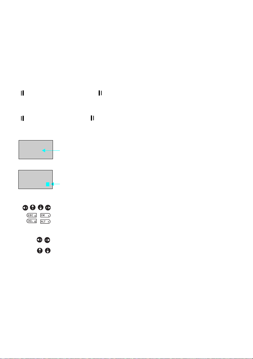
LANGUAGE
ENGLISH
Indicates that the display (the word “LANGUAGE” in this case) is
flashing. In this manual, this state is described by saying that the
“flashing cursor” is at the word “LANGUAGE”. In this state it is
possible to change settings and the position of the cursor.
Indicates that the display (the letter “H” in this case) is flashing in
reverse video. In this manual, this state is described by saying that
the “highlighted cursor” is at the word “H”. In this state it is not
possible to change settings but the cursor can be changed to the
flashing cursor by pressing the OK button.
Indicate the buttons that needs to be pressed in operating
procedures. Press each button once.
Indicate buttons that needs to be pressed in operating procedures.
Press one of the buttons once or more.
OMRON, 2006
All rights reserved. No part of this publication may be reproduced, stored in a retrieval
system, or transmitted, in any form, or by any means, mechanical, electronic, photocopying,
recording, or otherwise, without the prior written permission of OMRON.
No patent liability is assumed with respect to the use of the information contained herein.
Moreover, because OMRON is constantly striving to improve its high-quality products, the
information contained in this manual is subject to change without notice. Every precaution
has been taken in the preparation of this manual. Nevertheless, OMRON assumes no
responsibility for errors or omissions. Neither is any liability assumed for damages resulting
from the use of the information contained in this publication.
x

TABLE OF CONTENTS
Preface. . . . . . . . . . . . . . . . . . . . . . . . . . . . . . . . . . . . . . . . . . . . . . . . . . . . . . . . . iv
Warranty and Application Considerations . . . . . . . . . . . . . . . . . . . . . . . . . . . . . v
OMRON Product References . . . . . . . . . . . . . . . . . . . . . . . . . . . . . . . . . . . . . . . viii
Visual Aids . . . . . . . . . . . . . . . . . . . . . . . . . . . . . . . . . . . . . . . . . . . . . . . . . . . . . viii
About this Manual. . . . . . . . . . . . . . . . . . . . . . . . . . . . . . . . . . . . . . . . . . . . . . . . ix
Visual Aids . . . . . . . . . . . . . . . . . . . . . . . . . . . . . . . . . . . . . . . . . . . . . . . . . . . . . x
Precautions . . . . . . . . . . . . . . . . . . . . . . . . . . . . . . . . . . . . . . . . . xiii
Safety Precautions. . . . . . . . . . . . . . . . . . . . . . . . . . . . . . . . . . . . . . . . . . . . . . . . xiv
Precautions for Safe Use . . . . . . . . . . . . . . . . . . . . . . . . . . . . . . . . . . . . . . . . . . . xvi
Precautions for Correct Use . . . . . . . . . . . . . . . . . . . . . . . . . . . . . . . . . . . . . . . . xix
Conformance to EC Directives . . . . . . . . . . . . . . . . . . . . . . . . . . . . . . . . . . . . . . xxi
SECTION 1
Outline . . . . . . . . . . . . . . . . . . . . . . . . . . . . . . . . . . . . . . . . . . . . . 1
1-1 Outline . . . . . . . . . . . . . . . . . . . . . . . . . . . . . . . . . . . . . . . . . . . . . . . . . . . 2
1-2 Features and Models . . . . . . . . . . . . . . . . . . . . . . . . . . . . . . . . . . . . . . . . 8
1-3 Nomenclature and Basic Operation . . . . . . . . . . . . . . . . . . . . . . . . . . . . . 15
1-4 Memory Areas . . . . . . . . . . . . . . . . . . . . . . . . . . . . . . . . . . . . . . . . . . . . . 29
1-5 Allocating I/O Bit Numbers. . . . . . . . . . . . . . . . . . . . . . . . . . . . . . . . . . . 32
1-6 Preparations for Operation. . . . . . . . . . . . . . . . . . . . . . . . . . . . . . . . . . . . 33
SECTION 2
Installation and Wiring . . . . . . . . . . . . . . . . . . . . . . . . . . . . . . . 35
2-1 Mounting . . . . . . . . . . . . . . . . . . . . . . . . . . . . . . . . . . . . . . . . . . . . . . . . . 36
2-2 Wiring . . . . . . . . . . . . . . . . . . . . . . . . . . . . . . . . . . . . . . . . . . . . . . . . . . . 38
SECTION 3
Programming and Operating Methods . . . . . . . . . . . . . . . . . . 55
3-1 Selecting Display Language . . . . . . . . . . . . . . . . . . . . . . . . . . . . . . . . . . 57
3-2 Setting the Date and Time . . . . . . . . . . . . . . . . . . . . . . . . . . . . . . . . . . . . 58
3-3 Creating Ladder Programs. . . . . . . . . . . . . . . . . . . . . . . . . . . . . . . . . . . . 60
3-4 Confirming Ladder Program Operation. . . . . . . . . . . . . . . . . . . . . . . . . . 69
3-5 Correcting Ladder Programs . . . . . . . . . . . . . . . . . . . . . . . . . . . . . . . . . . 71
3-6 Using Timers (T) and Holding Timers (#). . . . . . . . . . . . . . . . . . . . . . . . 74
3-7 Using Counters (C) and the 8-Digit Counter (F) . . . . . . . . . . . . . . . . . . . 78
3-8 Using Weekly Timers (@) . . . . . . . . . . . . . . . . . . . . . . . . . . . . . . . . . . . . 81
3-9 Using Calendar Timers (*). . . . . . . . . . . . . . . . . . . . . . . . . . . . . . . . . . . . 86
3-10 Analog Inputs (Analog Comparators (A)). . . . . . . . . . . . . . . . . . . . . . . . 87
3-11 Comparing Timer/Counter Present Values Using Comparators (P) . . . . 91
xi

TABLE OF CONTENTS
3-12 Comparing the 8-Digit Counter (F) Present Value Using 8-Digit
Comparators (G). . . . . . . . . . . . . . . . . . . . . . . . . . . . . . . . . . . . . . . . . . . . 94
3-13 Displaying Messages (Display Bits (D)) . . . . . . . . . . . . . . . . . . . . . . . . . 96
3-14 Using Button Input Bits (B) . . . . . . . . . . . . . . . . . . . . . . . . . . . . . . . . . . . 99
SECTION 4
Special Functions. . . . . . . . . . . . . . . . . . . . . . . . . . . . . . . . . . . . . 101
4-1 Protecting Programs . . . . . . . . . . . . . . . . . . . . . . . . . . . . . . . . . . . . . . . . . 102
4-2 Stabilizing Input Operations. . . . . . . . . . . . . . . . . . . . . . . . . . . . . . . . . . . 104
4-3 Changing Backlight Automatic Cutout Time. . . . . . . . . . . . . . . . . . . . . . 106
4-4 Setting Daylight Saving Time (DST). . . . . . . . . . . . . . . . . . . . . . . . . . . . 107
4-5 Reading System Information . . . . . . . . . . . . . . . . . . . . . . . . . . . . . . . . . . 108
SECTION 5
Optional Products . . . . . . . . . . . . . . . . . . . . . . . . . . . . . . . . . . . . 109
5-1 Mounting Battery Units . . . . . . . . . . . . . . . . . . . . . . . . . . . . . . . . . . . . . . 110
5-2 Using Memory Cassettes . . . . . . . . . . . . . . . . . . . . . . . . . . . . . . . . . . . . . 111
5-3 Connecting the ZEN Support Software . . . . . . . . . . . . . . . . . . . . . . . . . . 114
SECTION 6
Troubleshooting. . . . . . . . . . . . . . . . . . . . . . . . . . . . . . . . . . . . . . 115
6-1 Troubleshooting . . . . . . . . . . . . . . . . . . . . . . . . . . . . . . . . . . . . . . . . . . . . 116
6-2 Error Messages. . . . . . . . . . . . . . . . . . . . . . . . . . . . . . . . . . . . . . . . . . . . . 116
6-3 Deleting Error Messages . . . . . . . . . . . . . . . . . . . . . . . . . . . . . . . . . . . . . 118
Appendices
A Specifications . . . . . . . . . . . . . . . . . . . . . . . . . . . . . . . . . . . . . . . . . . . . . 119
B Ladder Program Execution . . . . . . . . . . . . . . . . . . . . . . . . . . . . . . . . . . . 129
C Operating Mode at Startup . . . . . . . . . . . . . . . . . . . . . . . . . . . . . . . . . . . 133
D Version Upgrades . . . . . . . . . . . . . . . . . . . . . . . . . . . . . . . . . . . . . . . . . . 135
E Application Examples . . . . . . . . . . . . . . . . . . . . . . . . . . . . . . . . . . . . . . . 143
F Allocations and Setting Table . . . . . . . . . . . . . . . . . . . . . . . . . . . . . . . . . 157
Index . . . . . . . . . . . . . . . . . . . . . . . . . . . . . . . . . . . . . . . . . . . . . . . 165
Revision History . . . . . . . . . . . . . . . . . . . . . . . . . . . . . . . . . . . . . 169
xii

Precautions
This section provides precautions for using the ZEN Programmable Relays.
This information contained in this section is important for the safe and reliable
application of the ZEN. You must read this section and understand the information
before attempting to set up for a ZEN.
Safety Precautions . . . . . . . . . . . . . . . . . . . . . . . . . . . . . . . . . . . . . . . . . . . . . xiv
Precautions for Safe Use . . . . . . . . . . . . . . . . . . . . . . . . . . . . . . . . . . . . . . . . xvi
Precautions for Correct Use . . . . . . . . . . . . . . . . . . . . . . . . . . . . . . . . . . . . . . xix
Conformance to EC Directives . . . . . . . . . . . . . . . . . . . . . . . . . . . . . . . . . . . xxi
xiii
Precautions
Safety Precautions
Definition of Precautionary Information
The following notation is used in this manual to provide precautions required to
ensure safe usage of the product.
The safety precautions that are provided are extremely important to safety. Always
read and heed the information provided in all safety precautions.
The following notation is used.
Indicates a potentially hazardous situation which, if not avoided,
WARNING
will result in minor or moderate injury, or may result in serious
injury or death. Additionally, there may be significant property
damage.
CAUTION
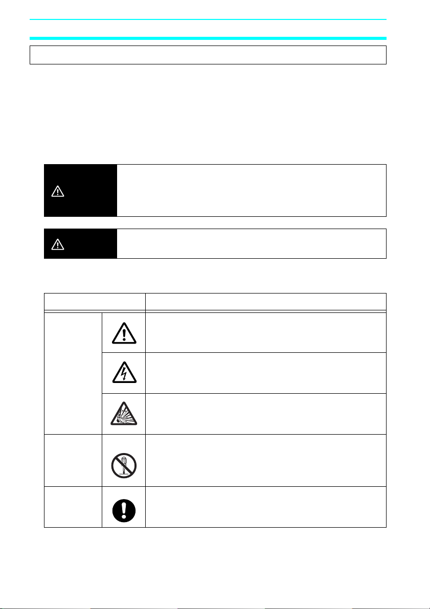
Symbols
Caution
Prohibition
Mandatory
Caution
Indicates a potentially hazardous situation which, if not avoided,
may result in minor or moderate injury or in property damage.
Symbol Meaning
General Caution
Indicates non-specific general cautions, warnings, and
dangers.
Electrical Shock Caution
Indicates possibility of electric shock under specific
conditions.
Explosion Caution
Indicates possibility of explosion under specific
conditions.
Disassembly Prohibition
Indicates prohibitions when there is a possibility of injury,
such as from electric shock, as the result of
disassembly.
General Caution
Indicates non-specific general cautions, warnings, and
dangers.
xiv
Precautions
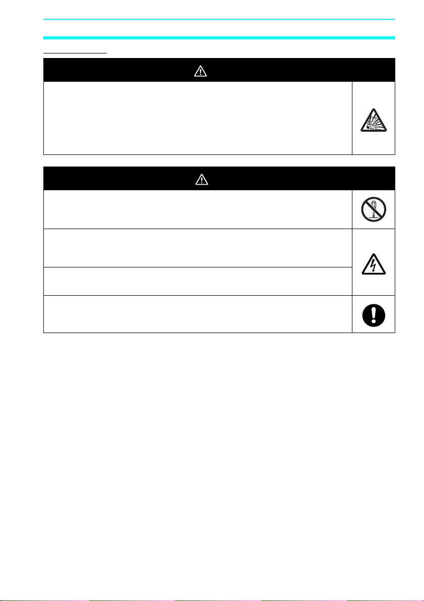
WARNING
Serious human hazard may occasionally occur due to ignition or rupture of
the lithium battery used in the Battery Unit. Do not short the battery
terminals or charge, disassemble, deform under pressure, or incinerate
the battery.
Never use any battery that has been dropped on the floor or otherwise
subjected to excessive shock.
CAUTION
Electric shock, fire, or malfunction may occur. Do not disassemble, modify,
or repair the ZEN or touch any of the internal parts.
Electrical shock may occur. Never touch the I/O terminals, computer
connector, Expansion Unit connector, or Battery Unit connector while
power is being supplied.
Electrical shock may occur. Do not remove the Expansion Unit connector
cover unless an Expansion I/O Unit will be permanently installed.
Fires may occasionally occur. Tighten the terminal screws to a torque of
0.565 to 0.6 N·m (5 to 5.3 in-lb).
Precautions
xv

Precautions
Precautions for Safe Use
Please observe the following precautions for safe use of this products.
Circuit Design
1. All interface connectors and battery connector are live parts, they may not be
directly connected to Softy Extra Low Voltage (SELV) circuit or to accessible
conductive parts.
For the programming units and Personal Computers use only the ZEN-CIF01
Connecting Cable (optional accessory) manufactured by OMRON.
ZEN-CIF01 provides safe (reinforced) insulation between Personal Computers
and ZEN.
2. Provide emergency stop circuits, external interlock circuits, limit circuits, and
other safety circuits in addition to any provided within the ZEN control circuits to
ensure safety of the overall system in the event of ZEN failure or external factors.
3. If the ZEN discovers an error during self-diagnosis, operation will be stopped and
all outputs will be turned OFF. As a countermeasure for such problems, external
safety measures must be provided to ensure safety in the overall system.
4. Outputs from the ZEN may remain ON or OFF due to faults in internal circuits
such as output relay fusing or burning, or output transistor destruction. As a
countermeasure for such problems, external safety measures must be provided
to ensure safety in the overall system.
5. Fail-safe measures must be taken by the user to ensure overall system safety in
the event of broken signal lines or momentary power interruptions.
6. The durability of the output relays is largely affected by the switching conditions.
Confirm the operation of the system under actual operating conditions and set
the switching frequency to ensure that adequate performance will be provided.
Insulation faults and burning in the ZEN may result if relays are used after their
performance has deteriorated.
Connecting Expansion I/O Units
1. Supply power to both the CPU Unit and Expansion I/O Units from the same
power supply and turn them ON and OFF at the same time.
2. When connecting Expansion I/O Units with DC inputs to a CPU Unit with an AC
power supply, the burst noise immunity will be 1 kV (IEC 61000-4-4).
3. Expansion I/O Units with AC inputs (ZEN-8E1AR) cannot be connected to a CPU
Unit with a DC power supply.
System Startup and Program Changes
1. Check the user program for proper execution before actually running it on the
Unit.
2. Disconnect the output lines from the system before testing operation in any
system in which incorrect operation can result in injury or equipment damage.
3. Confirm safety before attempting any of the following operations.
• Changing the operating mode (RUN/STOP).
xvi

Precautions
• Using the button switches.
• Changing bit status or parameter settings.
4. Double-check all wiring before turning ON the power supply.
5. Refer to Cycle Time Calculation Method on page 130 and confirm that the
increase in the cycle time will not affect operation. If the cycle time is too long, it
may become impossible to read input signals accurately. The increase in the
cycle time will be particularly noticeable when set values are written in RUN mode
for a CPU Unit with communications (ZEN-10C4@R-@-V2).
Installation and Wiring
1. Do not allow the ZEN to fall during installation.
2. Be sure that the DIN Track mounting levers, Expansion I/O Units, Memory
Cassettes, Battery Units, cable connectors, and other items with locking devices
are properly locked into place. Improper locking may result in malfunction.
3. When mounting the ZEN to the surface of the control panel, tighten mounting
screws to the following torques.
CPU Units: 1.03 N⋅m max.
Expansion I/O Units: 0.46 N⋅m max.
2
4. Use wires with cross-sectional areas of 0.2 to 2.5 mm
AWG14) for wiring and strip them for 6.5 mm.
Handling
1. The environment of use of ZEN is "Pollution degree 2" and "Overvoltage category
II" specified in IEC60664-1.
2. Always use the ZEN within the rated ambient operating temperature and
humidity. The rated ambient operating temperature is 0 to 55°C for LCD-type
CPU Units and –25 to 55°C for LED-type CPU Units. If the ZEN is used near
sources of heat, such as a power supply, the internal temperature of the ZEN may
increase, lowering the durability of the ZEN.
3. Discharge static electricity from your body, e.g., by touching a grounded metal
plate, before touching any Unit.
4. The exterior of the Units will be damaged if it comes into contact with organic
solvents (e.g., benzene or paint thinner), strong alkalies, or strong acids. Never
allow such substances to come into contact with the Units.
5. Do not apply voltages exceeding the rated voltages. Internal elements may be
destroyed.
6. Short failures or open failures may result from the destruction of output elements.
Do not use loads that exceed the rated output current.
Maintenance
When replacing a CPU Unit, transfer to the new Unit and confirm all settings for clock
data, internal holding bits, holding timers, and counters before starting operation
again.
Transportation and Storage
1. Use special packaging boxes when transporting the ZEN and do not subject it to
excessive shock or vibration or drop it during shipment.
(equivalent to AWG24 to
xvii

Precautions
2. Store the ZEN at an ambient temperature of −40 to 75°C for LED-type CPU Units
and −20 to 75°C for all other types of CPU Units. If the ZEN has been stored at
−10°C or lower, allow it to stand at room temperature for 3 hours or longer before
turning ON the power supply.
xviii

Precautions
Precautions for Correct Use
Installation Environment
1. Do not install the ZEN in the following locations.
• Locations subject to radical changes in temperature
• Location with high humidity subject to condensation
• Locations subject to excessive dust or dirt
• Locations subject to corrosive gas
• Locations subject to direct sunlight
2. Do not install the ZEN in locations subject to shock or vibration. Extended use in
such location may cause damage from stress.
3. In environments subject to static electricity (e.g., close to pipes conveying
forming materials, powders, or fluid materials), separate the ZEN as far as
possible from the source of static electricity.
4. The ZEN is neither waterproof nor oil-proof. Do not use it in locations subject to
water or oil.
5. Use the ZEN within the allowable power supply voltage range. Be particularly
careful in locations with bad power supply conditions, e.g., large fluctuations in
the power supply voltage.
6. Do not install the ZEN in locations subject to excessive noise, which may cause
the ZEN to fail.
7. Take appropriate and sufficient countermeasures when installing systems in the
following locations:
• Locations subject to strong electromagnetic fields
• Locations subject to possible exposure to radioactivity
Power Supply
1. Always turn OFF the power supply to the ZEN (CPU Unit and Expansion I/O
Units) before attempting any of the following.
• Assembling the ZEN
• Attaching or removing Expansion I/O Units
• Connecting or disconnecting any cables or wiring
• Attaching or removing the Memory Cassette
• Attaching or removing the Battery Unit
2. If the power supply is interrupted for 2 days or more (at 25°C
capacitor will discharge and internal bit status and the contents of PV areas will
be lost or corrupted and dates and times will be reset. When restarting operation
after the power supply has been interrupted for an extended period of time, check
the system in advance to confirm that no errors will occur.
Handling
1. Connect connectors only after confirming that the direction or polarity is correct.
2. Failures could result if dust or dirt enters the ZEN. Always connect the connector
cover to the computer connector whenever it is not being used.
), the internal
xix
Precautions
3. Do not remove the label from the left side of the CPU Unit if a Battery Unit is not
mounted.
Other
1. The execution of the ladder program in the ZEN is different from that for other
PLCs. Refer to Appendix B Ladder Program Execution when writing the ladder
program.
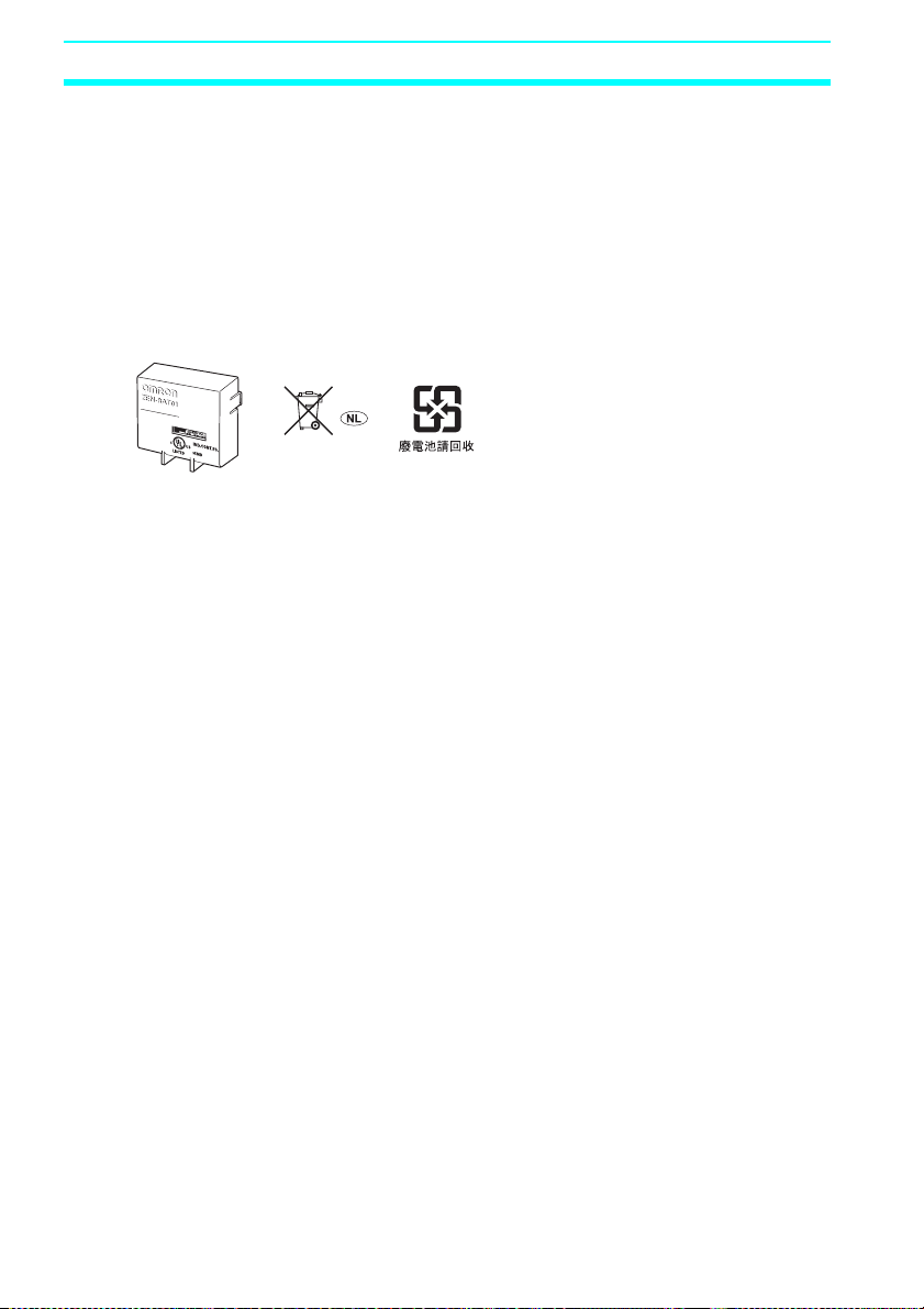
2. Abide by all local ordinances and regulations when disposing of the ZEN.
3. The Battery Unit (ZEN-BAT01, sold separately) contains a lithium battery.
Observe all applicable legal requirements for your area when disposing of the
lithium battery.
xx

Precautions
Conformance to EC Directives
Applicable Directives
•EMC Directives
• Low Voltage Directive
Concepts
EMC Directives
OMRON devices that comply with EC Directives also conform to the related EMC
standards so that they can be more easily built into other devices or the overall machine.
The actual products have been checked for conformity to EMC standards. The ZEN
complies with IEC/EN61131-2 clause 8. Whether the products conform to the standards
in the system used by the customer, however, must be checked by the customer.
EMC-related performance of the OMRON devices that comply with EC Directives will
vary depending on the configuration, wiring, and other conditions of the equipment or
control panel on which the OMRON devices are installed. The customer must, therefore,
perform the final check to confirm that devices and the overall machine conform to EMC
standards.
Low Voltage Directive
Always ensure that devices operating at voltages of 50 to 1,000 VAC and 75 to 1,500
VDC meet the required safety standards. The ZEN complies with IEC/EN61131-2 clause
11 except for 11.7.2.2.
Conformance to EC Directives
The ZEN complies with EC Directives. To ensure that the machine or device in which the
ZEN is used complies with EC Directives, the ZEN must be installed as follows:
1. The ZEN is an open-structure device. To meet the requirements of IEC/EN 61131-2
for open-structure devices, the ZEN must be mounted inside a control panel and
protected from mechanical impact as described on page 36.
2. Do not exceed a cable length of 10 m when connecting transistor outputs.
3. Burst immunity will no longer meet IEC/EN 61131-2 requirements if an Expansion I/O
Unit with DC inputs is connected to a CPU Unit with an AC power supply.
4. ZEN models complying with EC Directives also conform to the Common Emission
Standard (IEC/EN61131-2 clause 8). Radiated emission characteristics (10-m
regulations) may vary depending on the configuration of the control panel used, other
devices connected to the control panel, wiring, and other conditions. You must
therefore confirm that the overall machine or equipment complies with EC Directives.
xxi
Precautions
Relay Output Noise Reduction Methods
The ZEN conforms to EN 61131-2 of the EMC Directives. However, noise generated by
relay output switching may not satisfy these Standards. In such a case, a noise filter
must be connected to the load side or other appropriate countermeasures must be
provided external to the ZEN.
Countermeasures taken to satisfy the standards vary depending on the devices on the
load side, wiring, configuration of machines, etc. Following are examples of
countermeasures for reducing the generated noise.
Countermeasures
(Refer to EN61131-2 for more details.)
• Countermeasures are not required if the frequency of load switching for the whole
system with the ZEN included is less than 5 times per minute.
• Countermeasures are required if the frequency of load switching for the whole
system with the ZEN included is 5 times per minute or higher.
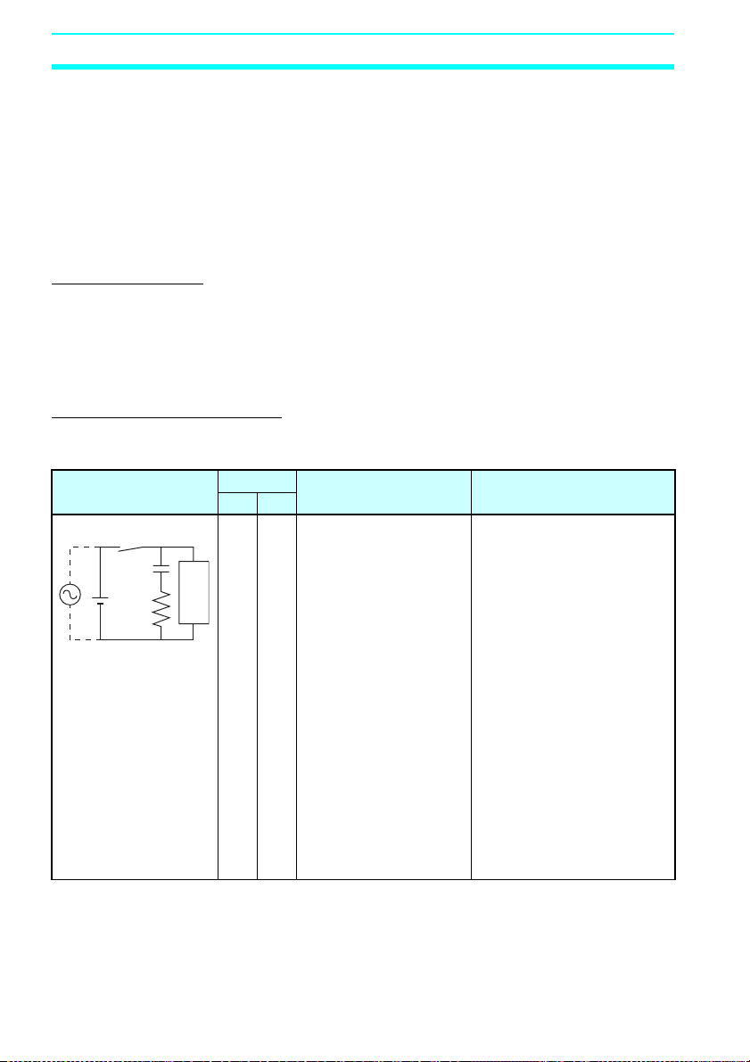
Countermeasure Examples
When switching an inductive load, connect an surge protector, diodes,
etc., in parallel with the load or contact as shown below.
Circuit Current Characteristic Required element
AC DC
CR method Yes Yes If the load is a relay or
C
R
Powe r
supply
Inductive
load
solenoid, there is a time
lag between the moment
the circuit is opened and
the moment the load is
reset.
If the supply voltage is 12
to 48 V, insert the surge
protector in parallel with
the load. If the supply
voltage is 100 to 200 V,
insert the surge protector
between the contacts.
The capacitance of the
capacitor must be 1 to 0.5
per contact current of 1 A and
resistance of the resistor must
be 0.5 to 1
voltage of 1 V. These values,
however, vary with the load
and the characteristics of the
relay. Decide these values
from experiments, and take
into consideration that the
capacitance suppresses spark
discharge when the contacts
are separated and the
resistance limits the current
that flows into the load when
the circuit is closed again.
The dielectric strength of the
capacitor must be 200 to
300 V. If the circuit is an AC
circuit, use a capacitor with no
polarity.
Ω per contact
µF
xxii
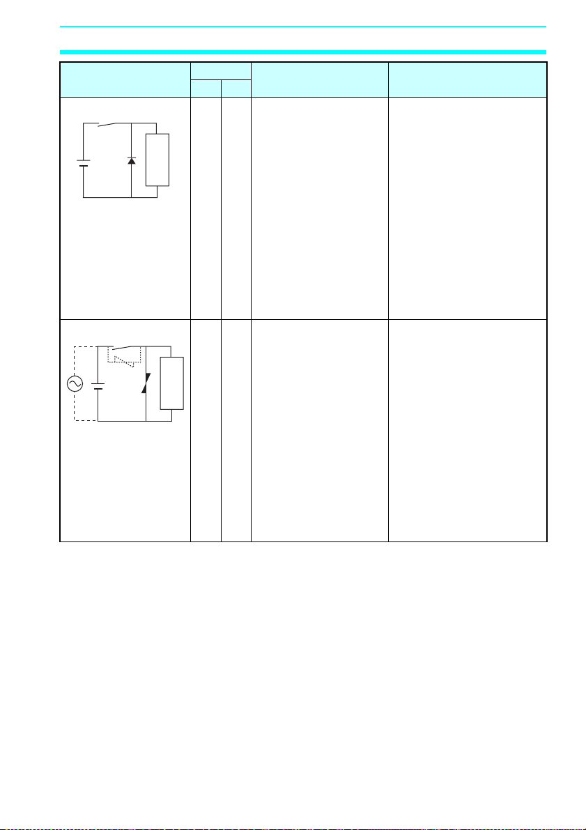
Circuit Current Characteristic Required element
AC DC
Diode method No Yes The diode connected in
Powe r
supply
Varistor method Yes Yes The varistor method
Powe r
supply
Inductive
load
Inductive
load
parallel with the load
changes energy
accumulated by the coil
into a current, which then
flows into the coil so that
the current will be
converted into Joule heat
by the resistance of the
inductive load.
This time lag, between
the moment the circuit is
opened and the moment
the load is reset, caused
by this method is longer
than that caused by the
CR method.
prevents the imposition of
high voltage between the
contacts by using the
constant voltage
characteristic of the
varistor. There is time lag
between the moment the
circuit is opened and the
moment the load is reset.
If the supply voltage is 12
to 48 V, insert the varistor
in parallel with the load. If
the supply voltage is 100
to 200 V, insert the
varistor between the
contacts.
Precautions
The reversed dielectric
strength value of the diode
must be at least 10 times as
large as the circuit voltage
value. The forward current of
the diode must be the same as
or larger than the load current.
The reversed dielectric
strength value of the diode
may be two to three times
larger than the supply voltage
if the surge protector is
applied to electronic circuits
with low circuit voltages.
---
xxiii

Precautions
xxiv

SECTION 1
Outline
This section gives an outline of the ZEN, including example applications, the system
configurations and basic operations.
1-1 Outline . . . . . . . . . . . . . . . . . . . . . . . . . . . . . . . . . . . . . . . . . . . . . . . . . . . . . . 2
1-2 Features and Models . . . . . . . . . . . . . . . . . . . . . . . . . . . . . . . . . . . . . . . . . . . 8
1-2-1 Features and System Configuration. . . . . . . . . . . . . . . . . . . . . . . . 8
1-2-2 List of Models . . . . . . . . . . . . . . . . . . . . . . . . . . . . . . . . . . . . . . . . 10
1-3 Nomenclature and Basic Operation . . . . . . . . . . . . . . . . . . . . . . . . . . . . . . . . 15
1-3-1 Nomenclature. . . . . . . . . . . . . . . . . . . . . . . . . . . . . . . . . . . . . . . . . 15
1-3-2 Screen Transitions . . . . . . . . . . . . . . . . . . . . . . . . . . . . . . . . . . . . . 20
1-3-3 Basic Operation . . . . . . . . . . . . . . . . . . . . . . . . . . . . . . . . . . . . . . . 24
1-4 Memory Areas . . . . . . . . . . . . . . . . . . . . . . . . . . . . . . . . . . . . . . . . . . . . . . . . 29
1-5 Allocating I/O Bit Numbers. . . . . . . . . . . . . . . . . . . . . . . . . . . . . . . . . . . . . . 32
1-6 Preparations for Operation. . . . . . . . . . . . . . . . . . . . . . . . . . . . . . . . . . . . . . . 33
1
Outline Section 1-1
1-1 Outline
Economical, Small-scale Automatic Control
One CPU Unit provides 12 inputs and 8 outputs (with CPU Unit with
20 I/O points).
Water-supply facilities in apartments,
lighting control in offices.
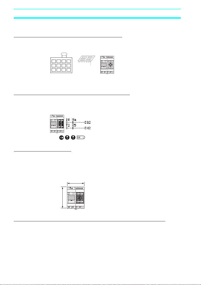
Easy Operation with an Inexpensive Controller
Ladder programming is possible directly from CPU Unit. When using
LED-type CPU Units (without LCD display) with Memory Cassettes
(optional), ladder programs can be easily copied.
Smaller Control Panels
The ZEN is very small at 90 x 70 x 56 mm (H x W x D) and mounts
essentially anywhere.
Note Dimensions are 90 x 122.5 x 56 mm (H x W x D) for CPU Units
with 20 I/O points.
70 mm
90 mm
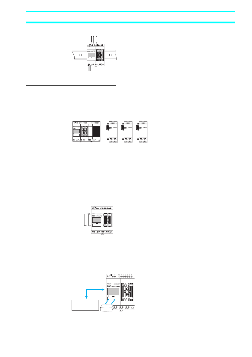
Less Assembly and Wiring Time Required for Control Panels
Simple one-touch DIN Track mounting. Built-in timers and counters
so only power supply and I/O circuit wiring required.
Solid wires can be easily connected using only a screwdriver.
2
Outline Section 1-1
Refer to page 38.
Future System Expandability
I/O capacity can be expanded to up to 24 inputs and 20 outputs by
connecting 3 Expansion I/O Units.
Refer to page 9 and 37.
CPU Unit
20C1AR-A-V2
Q
4
12 inputs/8 outputs + (4 inputs/4 outputs)
Expansion I/O Units (up to 3)
I6I7I8I9IaI
b
Q6Q5Q
7
× 3
Power Failure Countermeasures
EEPROM backs up the program and system settings data when no
power is supplied to the ZEN.
Use a Battery Unit (optional) to back up work bits, holding timers,
counters, and date/time data.
Refer to page 110.
Battery
Unit
Easy Saving and Copying of Programs
Use an optional Memory Cassette to easily save and copy programs.
Refer to page 111.
Ladder program
data/settings.
Memory Cassette
3
Outline Section 1-1
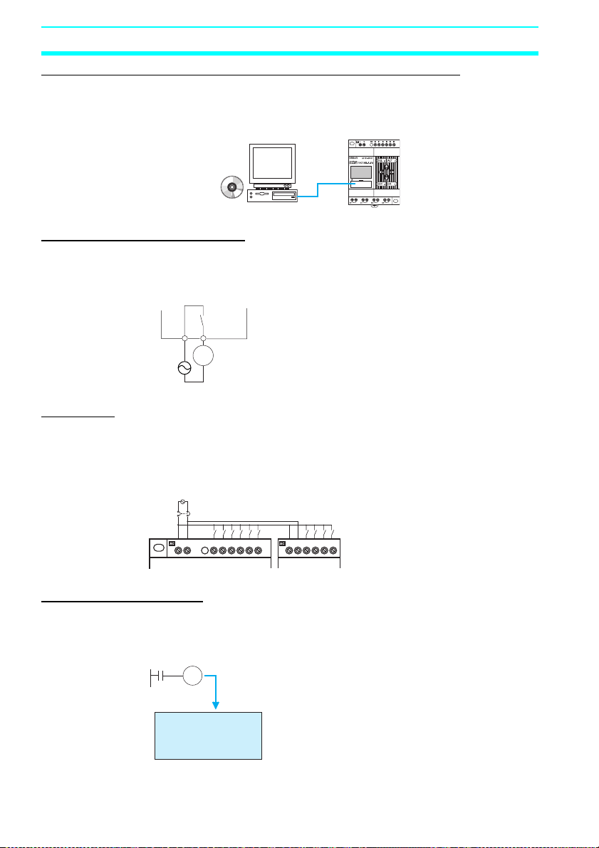
Programming and Monitoring from a Personal Computer
Windows-based ZEN Support Software is available and provides a
complete simulation function.
Refer to page 114.
ZEN Support
Software
(CD-ROM)
Greater Switching Capacity
The output contacts have 8-A switching capacity (250 VAC). All
contacts are independent (for CPU Units with 10 I/O points).
Refer to page 51.
8 A max.
MC
250 V
AC Inputs
For CPU Units with AC power supply inputs, 100 to 240 VAC can be
directly connected.
Refer to page 41.
100 to 240 VAC
LN
Circuit protector
L N NC I0 I1 I2 I3 I4 I5
Easy Program Design
There are 3 different operations that can be set for bit outputs. Selfholding bits also can be easily programmed.
Refer to page 65.
Ry
Normal operation
Set/reset operation
Alternate operation
4
L N IN0 IN1 IN2 IN3
Outline Section 1-1
Complicated Timers without Additional Programming
Any of the 16 timers support 5 types of operation and 3 timing
ranges.
There are also 8 built-in holding timers that hold data during power
interruptions.
Refer to page 74.
TIM
ON delay
OFF delay
One-shot pulse
Flashing pulse
Twin timer
0.01 to 99.99 s
1 s to 99 min 59 s
1 min to 99 h 59 min
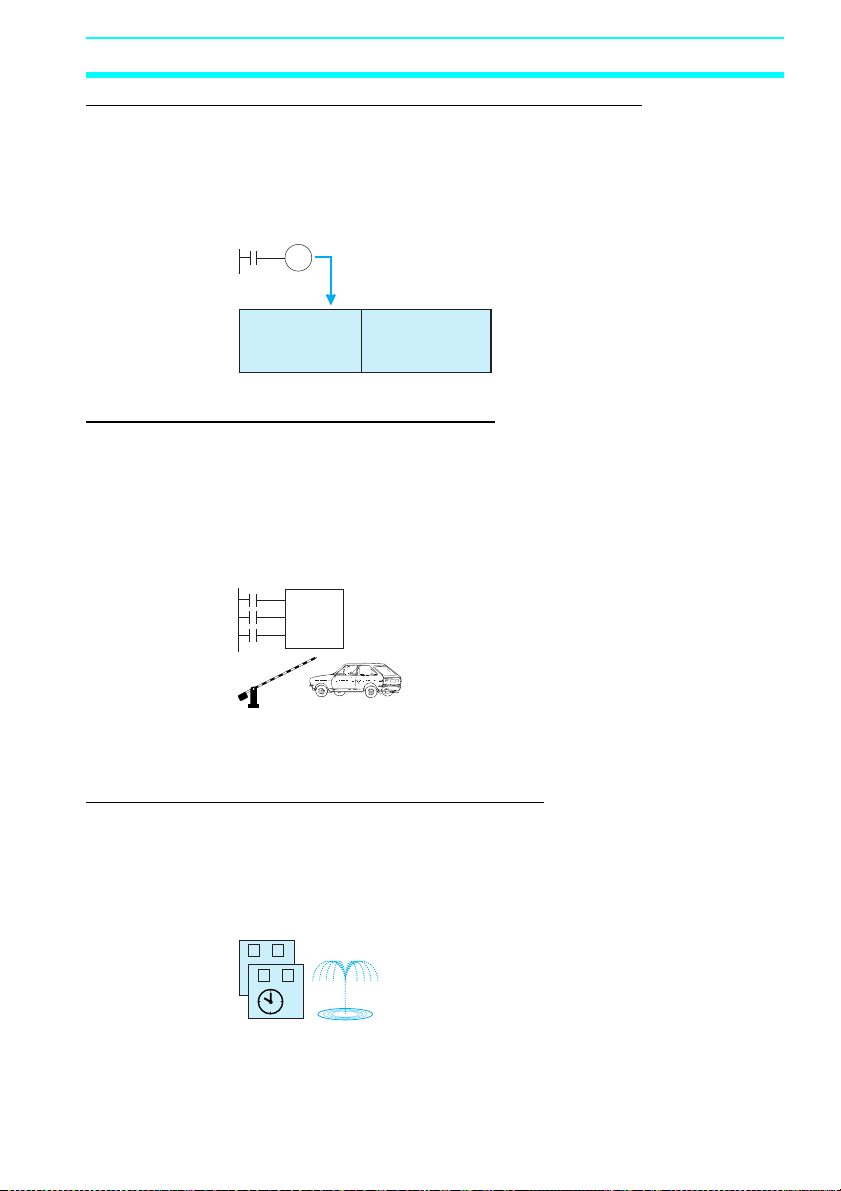
Incremental and Decremental Counters
There are 16 built-in counters that can be switched between
incrementing and decrementing.
Use Comparators to enable programming multiple outputs from a
counter.
Counters: Refer to page 78.
Comparators: Refer to page 91.
C
DRCNT
Control number of cars entering
and leaving a car park.
Season- or Day-dependent Operating Times
CPU Units with built-in calendar and clock functions have 16 weekly
timers and 16 calendar timers. Seasonal control is possible using
calendar timers and day/time control is possible with weekly timers.
Weekly timers: Refer to page 81.
Calendar timers: Refer to page 86.
MO FR
−
SA SU
−
For gardens, parks, and
recreational ponds.
5
Outline Section 1-1
Direct Analog Inputs
CPU Units with DC power supply inputs have 2 analog input points (0
to 10 V) and 4 analog comparators.
Refer to page 87.
Temperature control for hot
houses and tanks. Prevent
freezing of swimming pools.
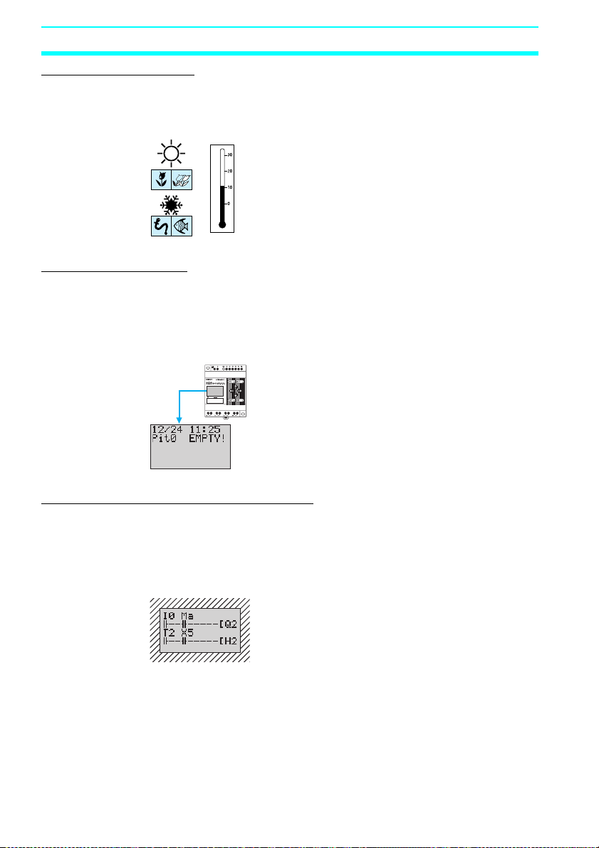
Easier Maintenance
Use the display function in CPU Units to display user-specified
messages, the date, time, or other data. Button switches can also be
used as input contacts. Applications include usage as a simple
display operation panel.
Refer to page 96.
Longer Backlight for Dark Situations
The automatic cutout time for the backlight for CPU Units can be set
to 2, 10, or 30 minutes, or set to operate continuously. With the
display function, the backlight can also be set to turn ON when a
message is displayed.
Refer to page 106.
6
 Loading...